EP0351977A2 - Pistons - Google Patents
Pistons Download PDFInfo
- Publication number
- EP0351977A2 EP0351977A2 EP89306759A EP89306759A EP0351977A2 EP 0351977 A2 EP0351977 A2 EP 0351977A2 EP 89306759 A EP89306759 A EP 89306759A EP 89306759 A EP89306759 A EP 89306759A EP 0351977 A2 EP0351977 A2 EP 0351977A2
- Authority
- EP
- European Patent Office
- Prior art keywords
- skirt
- head portion
- skirt portions
- piston according
- piston
- Prior art date
- Legal status (The legal status is an assumption and is not a legal conclusion. Google has not performed a legal analysis and makes no representation as to the accuracy of the status listed.)
- Withdrawn
Links
Images
Classifications
-
- F—MECHANICAL ENGINEERING; LIGHTING; HEATING; WEAPONS; BLASTING
- F02—COMBUSTION ENGINES; HOT-GAS OR COMBUSTION-PRODUCT ENGINE PLANTS
- F02F—CYLINDERS, PISTONS OR CASINGS, FOR COMBUSTION ENGINES; ARRANGEMENTS OF SEALINGS IN COMBUSTION ENGINES
- F02F3/00—Pistons
- F02F3/0015—Multi-part pistons
- F02F3/003—Multi-part pistons the parts being connected by casting, brazing, welding or clamping
-
- F—MECHANICAL ENGINEERING; LIGHTING; HEATING; WEAPONS; BLASTING
- F02—COMBUSTION ENGINES; HOT-GAS OR COMBUSTION-PRODUCT ENGINE PLANTS
- F02F—CYLINDERS, PISTONS OR CASINGS, FOR COMBUSTION ENGINES; ARRANGEMENTS OF SEALINGS IN COMBUSTION ENGINES
- F02F3/00—Pistons
- F02F3/02—Pistons having means for accommodating or controlling heat expansion
- F02F3/025—Pistons having means for accommodating or controlling heat expansion having circumferentially slotted piston skirts, e.g. T-slots
Definitions
- the present invention relates to pistons for reciprocating machines, for example, internal combustion engines or pumps.
- pistons are formed in one piece defining a head portion and skirt formation, bushes being provided in the skirt formation for engagement of a gudgeon pin by means of which the piston may be pivotally connected to a connecting rod.
- a piston comprises a head piston and an axially extending skirt formation, a gudgeon pin being supported transversely of the skirt formation by means of which the piston may be pivotally attached to a connecting rod characterised in that the skirt formation is defined by a pair of part cylindrical skirt portions, the gudgeon pin connecting the part cylindrical skirt portions together and means being provided to locate the skirt portions axially with respect to the head portion.
- the head portion and skirt portions may be made of dissimilar materials, for example, the head portion which is subjected to high temperature variations may be made of a ceramic material, while the skirt portions may be made of conventional alloy materials.
- the skirt portions of the present invention may also be resiliently urged apart and into engagement with the cylinder wall, thereby reducing backlash.
- the piston 10 illustrated in figures 1 and 2 comprises a piston head portion 11 having a pair of circumferential grooves 12 and 13 in which a piston ring and oil control ring (not shown) may be located in conventional manner.
- Skirt 14 of the piston 10 is formed from two semi-cylindrical skirt portions 15. Each skirt portion 15 defines a bearing formation 16 in which a gudgeon pin is slidingly located. A connecting rod (not shown) may also be pivotally mounted on the gudgeon pin 17 intermediate of the bearing formations 16, in conventional manner.
- skirt portions 15 are provided with inwardly directed flange formations 18 which engage in a circumferential groove 19 adjacent the lower end of piston head portion 11 to locate the skirt portion 15 axially of the head portion 11.
- Spring/damper units 21 act between the gudgeon pin 17 and the closed ends 20 of bearing formation 16, so that the skirt formations 15 are urged outwardly and, when the piston 10 is located within a cylindrical bore 22, into engagement with the walls of the cylinder bore 22.
- the semi-cylindrical skirt portions 15 each have a section the outer surface of which is defined by two eccentric quarter circles, so as to provide high spots 23 which engage the bore 22 of the cylinder at angularly spaced locations symmetrically of the bearing formations 16. Contact between the skirt portions 15 and the bore 22 and the frictional engagement therebetween, is thereby reduced.
- the head portion 11 may be formed from a plain cylindrical blank and the grooves 12, 13 and 19 may be machined therein. It is consequently possible to make the head portion 11 of, for example, a ceramic or refractory material and the skirt portions may be made from alloy materials used conventionally to produce pistons.
- the circumferential groove 19 is preferably made of sufficient depth to permit some relative movement between the head portion 11 and the skirt portions 15, so that the latter may move outwardly to engage the cylinder bore 22 and accommodate any wear therein.
- the piston head 11 will be centred in the bore 22 of the cylinder by means of the piston ring.
- the head portion 11 may be loaded resiliently with respect to the skirt portions 15 so that it is symmetrical or offset from the skirt portions 15, as desired.
Abstract
Description
- The present invention relates to pistons for reciprocating machines, for example, internal combustion engines or pumps.
- Conventionally, pistons are formed in one piece defining a head portion and skirt formation, bushes being provided in the skirt formation for engagement of a gudgeon pin by means of which the piston may be pivotally connected to a connecting rod.
- According to one aspect of the present invention, a piston comprises a head piston and an axially extending skirt formation, a gudgeon pin being supported transversely of the skirt formation by means of which the piston may be pivotally attached to a connecting rod characterised in that the skirt formation is defined by a pair of part cylindrical skirt portions, the gudgeon pin connecting the part cylindrical skirt portions together and means being provided to locate the skirt portions axially with respect to the head portion.
- In pistons of the above construction, the head portion and skirt portions may be made of dissimilar materials, for example, the head portion which is subjected to high temperature variations may be made of a ceramic material, while the skirt portions may be made of conventional alloy materials.
- In our co-pending European patent application claiming convention priority from UK Patent Application No. 8816983.4 we disclose a piston construction in which the head portion is formed asymmetrically of the skirt portion, so that the head portion may be maintained in engagement with one side of the cylinder wall, while accommodating thermal exansion of the head portion. In this construction, expansion of the head portion will result in tilting of the piston within the cylinder bore, and the piston must be designed accordingly. An alternative solution to this problem would be to use a piston in accordance with the present invention, the head portion being permitted to float laterally relative to the skirt portions to accommodate expansion of the head portion and means being provided to resiliently bias the head portion into engagement with one side of the cylinder.
- The skirt portions of the present invention may also be resiliently urged apart and into engagement with the cylinder wall, thereby reducing backlash. In this case, it would be advantageous to contour the skirt portions so that they engage the bore of the cylinder only at angularly spaced positions, said positions preferably being symmetrically arranged transversely opposed to the axis of the gudgeon pin.
- An embodiment of the invention is now described, by way of example only, with reference to the accompanying drawings, in which:-
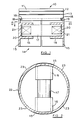
- Figure 1 is a sectional side elevation of a piston formed in accordance with the present invention; and
- Figure 2 is a section along the line II-II of Figure 1.
- The
piston 10 illustrated in figures 1 and 2 comprises apiston head portion 11 having a pair ofcircumferential grooves -
Skirt 14 of thepiston 10 is formed from twosemi-cylindrical skirt portions 15. Eachskirt portion 15 defines abearing formation 16 in which a gudgeon pin is slidingly located. A connecting rod (not shown) may also be pivotally mounted on thegudgeon pin 17 intermediate of thebearing formations 16, in conventional manner. - The upper ends of the
skirt portions 15 are provided with inwardly directedflange formations 18 which engage in acircumferential groove 19 adjacent the lower end ofpiston head portion 11 to locate theskirt portion 15 axially of thehead portion 11. - Spring/
damper units 21 act between thegudgeon pin 17 and the closedends 20 ofbearing formation 16, so that theskirt formations 15 are urged outwardly and, when thepiston 10 is located within acylindrical bore 22, into engagement with the walls of the cylinder bore 22. - The
semi-cylindrical skirt portions 15 each have a section the outer surface of which is defined by two eccentric quarter circles, so as to providehigh spots 23 which engage thebore 22 of the cylinder at angularly spaced locations symmetrically of thebearing formations 16. Contact between theskirt portions 15 and thebore 22 and the frictional engagement therebetween, is thereby reduced. - Resiliently loading and damping the
skirt portions 15 into engagement with thebore 22 of the cylinder, will reduce backlash or piston slap consequently improving engine wear and reducing the noise emmisions of the engine. - In the above embodiment, the
head portion 11 may be formed from a plain cylindrical blank and thegrooves head portion 11 of, for example, a ceramic or refractory material and the skirt portions may be made from alloy materials used conventionally to produce pistons. - The
circumferential groove 19 is preferably made of sufficient depth to permit some relative movement between thehead portion 11 and theskirt portions 15, so that the latter may move outwardly to engage thecylinder bore 22 and accommodate any wear therein. Under normal conditions, thepiston head 11 will be centred in thebore 22 of the cylinder by means of the piston ring. Alternatively, thehead portion 11 may be loaded resiliently with respect to theskirt portions 15 so that it is symmetrical or offset from theskirt portions 15, as desired.
Claims (13)
Applications Claiming Priority (2)
| Application Number | Priority Date | Filing Date | Title |
|---|---|---|---|
| GB8816981 | 1988-07-16 | ||
| GB888816981A GB8816981D0 (en) | 1988-07-16 | 1988-07-16 | Pistons |
Publications (2)
| Publication Number | Publication Date |
|---|---|
| EP0351977A2 true EP0351977A2 (en) | 1990-01-24 |
| EP0351977A3 EP0351977A3 (en) | 1990-04-25 |
Family
ID=10640584
Family Applications (1)
| Application Number | Title | Priority Date | Filing Date |
|---|---|---|---|
| EP89306759A Withdrawn EP0351977A3 (en) | 1988-07-16 | 1989-07-04 | Pistons |
Country Status (4)
| Country | Link |
|---|---|
| US (1) | US4961408A (en) |
| EP (1) | EP0351977A3 (en) |
| JP (1) | JPH0262478A (en) |
| GB (1) | GB8816981D0 (en) |
Cited By (3)
| Publication number | Priority date | Publication date | Assignee | Title |
|---|---|---|---|---|
| WO1991014889A2 (en) * | 1990-03-28 | 1991-10-03 | Keith Charles Sugden | Piston and piston sealing ring assemblies |
| DE10037887A1 (en) * | 2000-08-03 | 2002-02-14 | Mahle Gmbh | Piston-cylinder assembly for an internal combustion engine with a shaftless piston |
| DE10106578A1 (en) * | 2001-02-13 | 2002-08-22 | Mahle Gmbh | Lower part for a built piston |
Families Citing this family (3)
| Publication number | Priority date | Publication date | Assignee | Title |
|---|---|---|---|---|
| JP2893599B2 (en) * | 1989-10-05 | 1999-05-24 | セイコーエプソン株式会社 | Polarized light source and projection display |
| US6364565B1 (en) * | 2000-02-01 | 2002-04-02 | Caterpillar Inc. | Piston pin assembly |
| US6499387B2 (en) | 2001-03-06 | 2002-12-31 | Federal-Mogul World Wide, Inc. | Unified multi-piece piston and method of manufacture |
Citations (3)
| Publication number | Priority date | Publication date | Assignee | Title |
|---|---|---|---|---|
| GB319945A (en) * | 1928-10-11 | 1929-10-03 | Philip Keith Saunders | Improvements in pistons for use in internal combustion engines |
| US1795353A (en) * | 1930-03-12 | 1931-03-10 | Taylor Reginald | Piston |
| GB418651A (en) * | 1933-01-24 | 1934-10-29 | Karl Gustaf Oestberg | Improvements in or relating to pistons |
Family Cites Families (5)
| Publication number | Priority date | Publication date | Assignee | Title |
|---|---|---|---|---|
| US1279184A (en) * | 1913-10-22 | 1918-09-17 | Packard Motor Car Co | Piston. |
| US2113628A (en) * | 1936-09-09 | 1938-04-12 | George R Stull | Ringless piston |
| US3552276A (en) * | 1968-09-13 | 1971-01-05 | Joseph H Morrow | Expandable cylindrical piston |
| BR7806090A (en) * | 1978-09-15 | 1980-03-25 | Metal Leve Sa Ind Com | PISTON WITH INDEPENDENT SKIRT |
| US4508019A (en) * | 1982-03-29 | 1985-04-02 | Deere & Company | Reduced impact piston assembly |
-
1988
- 1988-07-16 GB GB888816981A patent/GB8816981D0/en active Pending
-
1989
- 1989-07-04 EP EP89306759A patent/EP0351977A3/en not_active Withdrawn
- 1989-07-11 US US07/378,023 patent/US4961408A/en not_active Expired - Fee Related
- 1989-07-14 JP JP1182393A patent/JPH0262478A/en active Pending
Patent Citations (3)
| Publication number | Priority date | Publication date | Assignee | Title |
|---|---|---|---|---|
| GB319945A (en) * | 1928-10-11 | 1929-10-03 | Philip Keith Saunders | Improvements in pistons for use in internal combustion engines |
| US1795353A (en) * | 1930-03-12 | 1931-03-10 | Taylor Reginald | Piston |
| GB418651A (en) * | 1933-01-24 | 1934-10-29 | Karl Gustaf Oestberg | Improvements in or relating to pistons |
Cited By (6)
| Publication number | Priority date | Publication date | Assignee | Title |
|---|---|---|---|---|
| WO1991014889A2 (en) * | 1990-03-28 | 1991-10-03 | Keith Charles Sugden | Piston and piston sealing ring assemblies |
| WO1991014889A3 (en) * | 1990-03-28 | 1991-11-28 | Keith Charles Sugden | Piston and piston sealing ring assemblies |
| GB2261492A (en) * | 1990-03-28 | 1993-05-19 | Keith Charles Sugden | Piston and piston sealing ring assemblies |
| GB2261492B (en) * | 1990-03-28 | 1994-08-24 | Keith Charles Sugden | Piston and piston sealing ring assemblies |
| DE10037887A1 (en) * | 2000-08-03 | 2002-02-14 | Mahle Gmbh | Piston-cylinder assembly for an internal combustion engine with a shaftless piston |
| DE10106578A1 (en) * | 2001-02-13 | 2002-08-22 | Mahle Gmbh | Lower part for a built piston |
Also Published As
| Publication number | Publication date |
|---|---|
| JPH0262478A (en) | 1990-03-02 |
| US4961408A (en) | 1990-10-09 |
| EP0351977A3 (en) | 1990-04-25 |
| GB8816981D0 (en) | 1988-08-17 |
Similar Documents
| Publication | Publication Date | Title |
|---|---|---|
| US3906923A (en) | Piston and cylinder construction | |
| US6357341B1 (en) | Piston of internal combustion engine | |
| US5072654A (en) | Piston and bearing assemblies | |
| US8100048B2 (en) | Pinless piston and connecting rod assembly | |
| US4683808A (en) | Light alloy piston for internal combustion engines | |
| EP2183492B1 (en) | Small end con rod guidance piston | |
| US4050360A (en) | Oil damped piston | |
| US6540403B1 (en) | Piston-pin bushing | |
| US7493850B2 (en) | Piston | |
| US7302884B2 (en) | Piston | |
| JPH05223170A (en) | Piston | |
| US4961408A (en) | Pistons for reciprocating machines | |
| JP2002528669A (en) | Carbon piston for internal combustion engine | |
| EP0449278B1 (en) | Connecting structure of piston and connecting rod | |
| US4796517A (en) | Metal piston and ceramic piston pin assembly | |
| US2130923A (en) | Piston land construction | |
| US5074264A (en) | Light alloy piston for internal combustion engines | |
| EP1943444B2 (en) | Piston | |
| US6520069B2 (en) | Piston pin for internal combustion engine | |
| RU2013672C1 (en) | Plain bearing for crankshaft supports of v-engines | |
| EP1448918A1 (en) | Piston for an internal combustion engine | |
| JP3625896B2 (en) | Oil ring with expander | |
| EP0654595B1 (en) | Piston for alternating volumetric engines | |
| JPH04231772A (en) | Piston for engine or motor | |
| US5537970A (en) | Apparatus and method for determining piston dimension |
Legal Events
| Date | Code | Title | Description |
|---|---|---|---|
| PUAI | Public reference made under article 153(3) epc to a published international application that has entered the european phase |
Free format text: ORIGINAL CODE: 0009012 |
|
| AK | Designated contracting states |
Kind code of ref document: A2 Designated state(s): DE FR GB IT SE |
|
| PUAL | Search report despatched |
Free format text: ORIGINAL CODE: 0009013 |
|
| AK | Designated contracting states |
Kind code of ref document: A3 Designated state(s): DE FR GB IT SE |
|
| 17P | Request for examination filed |
Effective date: 19900918 |
|
| 17Q | First examination report despatched |
Effective date: 19911209 |
|
| STAA | Information on the status of an ep patent application or granted ep patent |
Free format text: STATUS: THE APPLICATION IS DEEMED TO BE WITHDRAWN |
|
| 18D | Application deemed to be withdrawn |
Effective date: 19930202 |