EP1826889A1 - Verfahren und Vorrichtung zum Anbringen von Magneten - Google Patents
Verfahren und Vorrichtung zum Anbringen von Magneten Download PDFInfo
- Publication number
- EP1826889A1 EP1826889A1 EP06007298A EP06007298A EP1826889A1 EP 1826889 A1 EP1826889 A1 EP 1826889A1 EP 06007298 A EP06007298 A EP 06007298A EP 06007298 A EP06007298 A EP 06007298A EP 1826889 A1 EP1826889 A1 EP 1826889A1
- Authority
- EP
- European Patent Office
- Prior art keywords
- rotor
- magnet
- magnets
- holding device
- holding
- Prior art date
- Legal status (The legal status is an assumption and is not a legal conclusion. Google has not performed a legal analysis and makes no representation as to the accuracy of the status listed.)
- Granted
Links
- 238000000034 method Methods 0.000 title claims abstract description 18
- 239000000696 magnetic material Substances 0.000 claims abstract description 8
- 230000000295 complement effect Effects 0.000 claims description 6
- 239000000853 adhesive Substances 0.000 description 17
- 230000001070 adhesive effect Effects 0.000 description 17
- 238000004519 manufacturing process Methods 0.000 description 6
- 230000007797 corrosion Effects 0.000 description 3
- 238000005260 corrosion Methods 0.000 description 3
- 239000003973 paint Substances 0.000 description 3
- 238000002360 preparation method Methods 0.000 description 2
- 238000004026 adhesive bonding Methods 0.000 description 1
- XAGFODPZIPBFFR-UHFFFAOYSA-N aluminium Chemical compound [Al] XAGFODPZIPBFFR-UHFFFAOYSA-N 0.000 description 1
- 229910052782 aluminium Inorganic materials 0.000 description 1
- 230000004323 axial length Effects 0.000 description 1
- 239000003292 glue Substances 0.000 description 1
- 238000002955 isolation Methods 0.000 description 1
- 239000000463 material Substances 0.000 description 1
- 239000002985 plastic film Substances 0.000 description 1
- 229920006255 plastic film Polymers 0.000 description 1
- 238000009417 prefabrication Methods 0.000 description 1
- 230000011218 segmentation Effects 0.000 description 1
- 230000035939 shock Effects 0.000 description 1
- 238000003892 spreading Methods 0.000 description 1
- 230000007704 transition Effects 0.000 description 1
Images



Classifications
-
- H—ELECTRICITY
- H02—GENERATION; CONVERSION OR DISTRIBUTION OF ELECTRIC POWER
- H02K—DYNAMO-ELECTRIC MACHINES
- H02K15/00—Processes or apparatus specially adapted for manufacturing, assembling, maintaining or repairing of dynamo-electric machines
- H02K15/02—Processes or apparatus specially adapted for manufacturing, assembling, maintaining or repairing of dynamo-electric machines of stator or rotor bodies
- H02K15/03—Processes or apparatus specially adapted for manufacturing, assembling, maintaining or repairing of dynamo-electric machines of stator or rotor bodies having permanent magnets
-
- Y—GENERAL TAGGING OF NEW TECHNOLOGICAL DEVELOPMENTS; GENERAL TAGGING OF CROSS-SECTIONAL TECHNOLOGIES SPANNING OVER SEVERAL SECTIONS OF THE IPC; TECHNICAL SUBJECTS COVERED BY FORMER USPC CROSS-REFERENCE ART COLLECTIONS [XRACs] AND DIGESTS
- Y10—TECHNICAL SUBJECTS COVERED BY FORMER USPC
- Y10T—TECHNICAL SUBJECTS COVERED BY FORMER US CLASSIFICATION
- Y10T29/00—Metal working
- Y10T29/49—Method of mechanical manufacture
- Y10T29/49002—Electrical device making
- Y10T29/49009—Dynamoelectric machine
-
- Y—GENERAL TAGGING OF NEW TECHNOLOGICAL DEVELOPMENTS; GENERAL TAGGING OF CROSS-SECTIONAL TECHNOLOGIES SPANNING OVER SEVERAL SECTIONS OF THE IPC; TECHNICAL SUBJECTS COVERED BY FORMER USPC CROSS-REFERENCE ART COLLECTIONS [XRACs] AND DIGESTS
- Y10—TECHNICAL SUBJECTS COVERED BY FORMER USPC
- Y10T—TECHNICAL SUBJECTS COVERED BY FORMER US CLASSIFICATION
- Y10T29/00—Metal working
- Y10T29/49—Method of mechanical manufacture
- Y10T29/49002—Electrical device making
- Y10T29/49009—Dynamoelectric machine
- Y10T29/49012—Rotor
-
- Y—GENERAL TAGGING OF NEW TECHNOLOGICAL DEVELOPMENTS; GENERAL TAGGING OF CROSS-SECTIONAL TECHNOLOGIES SPANNING OVER SEVERAL SECTIONS OF THE IPC; TECHNICAL SUBJECTS COVERED BY FORMER USPC CROSS-REFERENCE ART COLLECTIONS [XRACs] AND DIGESTS
- Y10—TECHNICAL SUBJECTS COVERED BY FORMER USPC
- Y10T—TECHNICAL SUBJECTS COVERED BY FORMER US CLASSIFICATION
- Y10T29/00—Metal working
- Y10T29/49—Method of mechanical manufacture
- Y10T29/49002—Electrical device making
- Y10T29/4902—Electromagnet, transformer or inductor
- Y10T29/49075—Electromagnet, transformer or inductor including permanent magnet or core
-
- Y—GENERAL TAGGING OF NEW TECHNOLOGICAL DEVELOPMENTS; GENERAL TAGGING OF CROSS-SECTIONAL TECHNOLOGIES SPANNING OVER SEVERAL SECTIONS OF THE IPC; TECHNICAL SUBJECTS COVERED BY FORMER USPC CROSS-REFERENCE ART COLLECTIONS [XRACs] AND DIGESTS
- Y10—TECHNICAL SUBJECTS COVERED BY FORMER USPC
- Y10T—TECHNICAL SUBJECTS COVERED BY FORMER US CLASSIFICATION
- Y10T29/00—Metal working
- Y10T29/49—Method of mechanical manufacture
- Y10T29/49002—Electrical device making
- Y10T29/4902—Electromagnet, transformer or inductor
- Y10T29/49075—Electromagnet, transformer or inductor including permanent magnet or core
- Y10T29/49078—Laminated
-
- Y—GENERAL TAGGING OF NEW TECHNOLOGICAL DEVELOPMENTS; GENERAL TAGGING OF CROSS-SECTIONAL TECHNOLOGIES SPANNING OVER SEVERAL SECTIONS OF THE IPC; TECHNICAL SUBJECTS COVERED BY FORMER USPC CROSS-REFERENCE ART COLLECTIONS [XRACs] AND DIGESTS
- Y10—TECHNICAL SUBJECTS COVERED BY FORMER USPC
- Y10T—TECHNICAL SUBJECTS COVERED BY FORMER US CLASSIFICATION
- Y10T29/00—Metal working
- Y10T29/49—Method of mechanical manufacture
- Y10T29/4998—Combined manufacture including applying or shaping of fluent material
-
- Y—GENERAL TAGGING OF NEW TECHNOLOGICAL DEVELOPMENTS; GENERAL TAGGING OF CROSS-SECTIONAL TECHNOLOGIES SPANNING OVER SEVERAL SECTIONS OF THE IPC; TECHNICAL SUBJECTS COVERED BY FORMER USPC CROSS-REFERENCE ART COLLECTIONS [XRACs] AND DIGESTS
- Y10—TECHNICAL SUBJECTS COVERED BY FORMER USPC
- Y10T—TECHNICAL SUBJECTS COVERED BY FORMER US CLASSIFICATION
- Y10T29/00—Metal working
- Y10T29/53—Means to assemble or disassemble
- Y10T29/5313—Means to assemble electrical device
- Y10T29/53143—Motor or generator
Definitions
- the invention relates to a method and a device for attaching magnets to components made of magnetic materials.
- the method according to the invention and the corresponding device are provided in particular for the production of rotors with permanent magnets for electric motors, in particular for electric motors for elevators.
- the rotors can be designed as internal rotor with permanent magnets attached to the outside, or as external rotor with permanent magnets attached to the inside. In order to properly equip the rotor with permanent magnets, a relatively large effort is required.
- a known method provides that, for example, plastic films or aluminum strips are glued to the rotor surface, which have been provided with recesses with the respective magnetic form. Then, an adhesive is applied in each case to the back of the magnets and these are inserted individually into the recesses. Care must be taken to ensure that the magnets, despite their magnetic force, are correctly and cleanly inserted in their recesses, as they are strongly attracted directly by the rotor surface and by the magnets already positioned. Because the magnets Always stick with a small gap from one magnet to the other, there is a risk of slippage and it must wait for each magnet until the adhesive has cured before the next magnet can be glued. Thus, this type of rotor production is very time consuming.
- EP 1 605 574 A1 It is known how the manufacturing costs can be reduced by segmentation of the rotor surface in pole faces and a prefabrication of the pole faces. In this case, however, a guided arm or an actuator is required for each pole around the rotor during assembly of the finished rotor, which leads to great expense in many poles. In addition, the magnets must still be applied to the pole faces and fixed on them.
- the inventive method is used for applying at least one magnet on a component made of a magnetic material, wherein the at least one magnet is applied to a surface of the component, wherein the at least one magnet in the immediate vicinity of the component, in a holding device by means of a holding element held holding force, is positioned and by deactivating the retaining element, the acting holding force is reduced and the at least one magnet merges onto a surface of the component.
- the method for producing an electric motor with a rotor with magnets and with a stator is used.
- the magnets are adhesively bonded to a surface of the rotor pointing in the direction of the stator, wherein the magnets for application to the rotor surface are first arranged in the holding device, which extends complementary to the rotor surface.
- each magnet array reaching around the pole circumference is inserted in pockets of a holding device, provided with adhesive, and then the entire magnet row is applied to one another on the rotor surface. It is advantageous that the time required for curing, for example, 90 seconds, for all magnets simultaneously and thus only once incurred. It is also advantageous that with the use of the method and the holding device slipping of the magnets after application to the rotor surface is not possible, since the magnets still protrude even after skipping from the device pockets on the rotor surface something in the pockets, as they are, for example mm are thick and the distance holding device to the rotor is only 3 mm.
- the holding device In the method according to the invention can be positioned after applying a reaching around the rotor circumference magnetic series on the rotor surface, the holding device with a new series of magnets directly adjacent to the already applied magnetic series and then the new magnetic series are applied next to the already applied magnetic series.
- the at least one magnet is adhered to the surface.
- the method according to the invention is carried out robotically supported in an embodiment.
- an electric motor having a rotor with permanent magnets and with a stator, in which the permanent magnets are to be bonded to a surface of the rotor facing in the direction of the stator, the magnets for application to the rotor surface first on a arranged opposite rotor surface shaped device, then positioned together at a small distance from the rotor surface and then applied to the rotor surface.
- the rotor is firmly positioned at least in a prepared state for the bond and that a reaching around the rotor circumference magnetic series for application to the rotor surface is first arranged on an opposite or complementary to the rotor surface shaped device, then Adhesive is applied to the free magnetic surface, then the device is positioned at a short distance to the rotor surface and then the magnets are applied together to the rotor surface.
- the treatment of the rotor surface can be done with robot support or even performed only by a robot.
- the robot can bring the rotor from a conveyor to a preparation station, pretreat the rotor surface to be bonded, position the rotor on a magnetic gluing station, position the device in a loading place, apply adhesive to the magnets with the aid of a dosing device, the device Position near the rotor surface, bring the magnets from the device to the rotor surface, bring the device to the loading place, bring the rotor from the magnetic adhesive on a conveying device, position the rotor in a paint booth, apply at least on the magnet - bonded rotor area corrosion protection and the Place the rotor on a transfer device.
- the magnet When placing the magnet on the magnetic field in the holding device, the magnet itself is held by its magnetic force at a pin located under each magnetic space in an embodiment. After positioning the holding device at a small distance from the rotor surface, the magnet is released from the pin by pulling the pin and brought by its own magnetic force to the rotor surface and holds there until the adhesive has cured.
- so-called ejector may be arranged to assist a release of the magnets from the pockets in the holder, if the magnets jam by presentedifferenzen in the pockets.
- the ejectors allow a defined pushing out of the magnets from the device.
- pins parallel to Magnetic surface are at least partially pulled out of the magnetic field, so that then the arranged at the pin ends ejector solve the not yet passed magnets from the pockets and then fold the magnets by its own magnetic force to the rotor surface.
- the pens may be grouped so that the pens of a group are moved together and that the different groups are moved one after another or simultaneously.
- a simultaneous movement of the pins is supported by the fact that they are connected together via one end and so can be moved simultaneously.
- the adhesive is applied in a finely dosed manner to the individual magnets, the layer thickness resulting after curing being used for the metering.
- the holding device according to the invention is used for applying at least one magnet.
- the device described is used in particular for carrying out a method described above.
- the holding device comprises a surface area which is complementary to a surface of a component on which the magnets are to be applied, wherein at least one deactivatable holding element is provided for causing or exerting a force on the at least one magnet to be arranged on the surface area ,
- the surface area of the device is in particular dimensioned such that spaces are provided for a magnet array provided around a rotor circumference and a movable pin is arranged as a holding element under each magnetic location.
- At least one guide for the at least one magnet is provided on the surface region of the device in an embodiment.
- At least the surface area of the device may consist of a nonmagnetic material and the at least one holding element of a magnetic material.
- the magnet may stick to the pin of magnetic material when inserted into the device.
- the magnets are held by a self-magnetic pin.
- the holding device can be positioned on a hub of a rotor at a small distance from a rotor surface by means of a sleeve.
- the axial lengths of the rotor, holding device and rotor holding device with sleeve are such that the radially correct position of the holding device is reached before the magnets arranged on the holding device reach an overlapping position with the rotor surface to be bonded.
- the device for carrying out the method comprises in an embodiment a device body which has a surface area with a magnet surface to be populated with a matching, in a small distance complementary shape, wherein on this surface at least for a provided around the rotor circumference magnetic series places are provided Form of pockets with the depth of the magnetic thickness and under each magnetic space a movable pin is arranged as a holding element for holding the magnet to be inserted into the pocket.
- the pin is arranged under the pocket so that it is movable in the longitudinal direction and with its outer surface just reached the pocket surface and thus just touched a lying in the pocket magnet with a thin strip of its surface. After deactivating or removing the pin from the lower magnetic surface, the magnet is no longer held on the holding device.
- the robot for carrying out the rotor production.
- the rotor is lifted by the robot, for example, from a delivery device to be delivered to a preparation station.
- the device positioned on a placement site is advantageously equipped with magnets by an employee by positioning the magnets in the pockets and visually checking for breaks, damage and corrosion. Equipping with magnets could also be done by the robot.
- the robot uses an adhesive device to apply glue to the magnets in the device. It is advantageous if the adhesive device has a dosing device that doses the amount of adhesive applied to a magnet pressure and time, while the robot performs the appropriate movements to distribute the adhesive thinly and evenly on the magnet.
- the robot After spreading the adhesive, the robot brings the device to the rotor and positions it near the rotor surface, so that the magnets are positioned directly opposite their intended locations on the rotor surface. Then, the robot pulls the pins holding the magnets in the device out of its holding position, and with the ejectors at the ends of the pins, the magnets are released from their device location and jump onto the rotor surface.
- the robot After waiting for the adhesive curing time, which may be, for example, 90 seconds, the robot brings the device back to the loading place and then the rotor from the magnetic adhesive place on a researcher detailvoriques. Thereafter, the robot positions the rotor in a paint booth and the robot applies paint to at least the area of the magnetized rotor surface to protect the magnets from corrosion. Then the rotor is moved by the robot to another conveyor.
- the device on the surface on which the magnets are to be arranged on magnetic fields in the form of pockets which correspond to the shape of the magnets and can serve as a guide.
- the magnets fit exactly in these pockets.
- a recess for a pin displaceable therein in the axial direction is arranged in the holding device in the axial direction as a holding element.
- the pins can be divided into groups and the pins of a group can be connected to one another via one end and be movable with each other by means of the connection.
- the pins have at their end arranged under the pocket a preferably non-magnetic ejector, which projects beyond the magnet facing side of the pin.
- the holding device which can be positioned over at least a region of its inner or outer contour in relation to the rotor surface to be bonded, is preferably positionable directly on the inner or the outer contour of the rotor.
- FIG. 1 schematically shows a detail of a holding device, which is denoted overall by the reference numeral 10.
- a device body 12 a magnetic pin 14, a connection 16 for pins 14, a rotor surface to be bonded 18 of a rotor 19, a magnetic plate 20 and a non-magnetic ejector 22nd
- the magnetic plate 20 initially holds with its own magnetic force on the pin 14 in the device body 12. By pulling up the pin 14 reduces the Kochdekkungs Colour and thus the magnetic attraction between the magnetic plate 20 and pin 14.
- the magnetic plate 20 jumps to the surface 18 of the rotor 19 on, additionally supported by the non-magnetic ejector 22.
- the rotor 19 facing surface 24 of the magnetic disk 20 is coated with adhesive.
- a recess 26, in which the pin 14 is received, provides a sliding or running surface 28 for the ejector 22nd
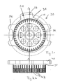
- FIG. 2 a shows a holding device 30 according to the invention with a device body 31 in plan view.
- holes 32 for aligning the magnet array offset and a handle 34 for manually aligning the device 30 can be seen, wherein the handle 34 is formed on the support plate 40.
- recesses 36 are shown for pins and pockets 38 for applied magnets.
- FIG. 2b shows a side view of the holding device 30.
- the device body 31 with the support plate 40 and magnetic locations 42 are shown.
- FIG. 10 A section of a further holding device 50 is shown in FIG. It includes a rotor 52, a magnet 54 skipped on the rotor 52, an ejector 56, an extended pin 58, a connection 60 of pins 58, a handle 62 for extracting the pins 58, a sleeve 64 Device body 66, a recess 68, an inserted pin 70, a holding device 50 to the holding magnet 72 and a support plate 74 to recognize.
- a small distance 76 between the rotor surface and magnet 72 which is about 3 mm.
- FIG. 4 shows two magnets 82 attached to a holding device 80. These magnets are held on the holding device 80 by means of a holding element (not shown) and are positioned by means of pins 84. These pins 84, each forming a pocket for the respective magnet 82, provide a guide for the magnet 82. That is, they are sufficiently long, e.g. with the height of the magnet thickness, the magnets 82 are still passed between the pins 84 after passing from the retainer 80 to a rotor (not shown). After the curing time of the adhesive used has expired, the holding device 80 can be moved upwards so that the magnets 82 pass out of the pockets formed by the pins 82.
- FIG. 5 shows a recess 90 for receiving the pin (not shown).
- a magnet 92 is held by magnetic attraction by means of the pin.
- the pin can touch the magnet 92 or there may be a narrow gap between magnet 92 and pin.
- the illustration also shows a tread 94 for the pen-mounted ejector 56 and a step 96 for a clean transition from the pocket 90 to the pocket 91.
Landscapes
- Engineering & Computer Science (AREA)
- Manufacturing & Machinery (AREA)
- Power Engineering (AREA)
- Permanent Field Magnets Of Synchronous Machinery (AREA)
Abstract
Description
- Die Erfindung betrifft ein Verfahren und eine Vorrichtung zum Anbringen von Magneten auf Bauteilen aus magnetischen Werkstoffen.
- Das erfindungsgemäße Verfahren und die entsprechende Vorrichtung werden insbesondere zur Herstellung von Rotoren mit Permanentmagneten für Elektromotoren, insbesondere für Elektromotoren für Aufzüge, bereitgestellt.
- Seit einigen Jahren werden für Aufzugsantriebe Motoren mit Rotoren verwendet, die mit Permanentmagneten bestückt sind. Dabei können die Rotoren als Innenläufer mit an der Außenseite angebrachten Permanentmagneten, oder als Außenläufer mit an der Innenseite angebrachten Permanentmagneten ausgebildet sein. Um den Rotor ordnungsgemäß mit Permanentmagneten zu bestücken, ist ein verhältnismäßig großer Aufwand erforderlich.
- Ein bekanntes Verfahren sieht vor, dass auf die Rotoroberfläche bspw. Kunststoffolien oder Aluminiumstreifen aufgeklebt werden, die mit Aussparungen mit der jeweiligen Magnetform versehen worden sind. Dann wird jeweils auf die Rückseite der Magnete ein Klebstoff aufgebracht und diese einzeln in die Aussparungen eingelegt. Dabei muss darauf geachtet werden, dass die Magnete trotz ihrer Magnetkraft richtig und sauber in ihre Aussparungen eingefügt werden, da sie unmittelbar von der Rotorfläche und von den bereits positionierten Magneten stark angezogen werden. Da die Magnete stets mit einem kleinen Spalt von einem zum anderen Magneten angeklebt werden müssen, besteht die Gefahr eines Verrutschens und es muss bei jedem Magnet abgewartet werden, bis der Klebstoff ausgehärtet ist, bevor der nächste Magnet geklebt werden kann. Somit ist diese Art der Rotorherstellung sehr zeitaufwendig.
- Aus der Druckschrift
EP 1 255 343 A2 ist ein Verfahren bekannt, bei dem die Magnete in einer Reihe auf einem Ring angeordnet werden und dann so viele Ringe nebeneinander auf einem Basisringkörper befestigt werden, wie für den Motor notwendig sind. Hierbei wird erreicht, dass die Ringe mit den Magneten um einen kleinen Winkel zueinander verdreht angeordnet werden können, um Stöße im Motorrundlauf am Anfang und am Ende der Magnete zu verringern bzw. vollständig zu vermeiden. Hierbei ist jedoch nach wie vor problematisch, dass die Magnete einzeln auf den Ringen befestigt werden müssen und dass die Ringe auf dem Basiskörper unter Vermeidung von Unwuchten zu befestigen sind. - Aus einer weiteren Druckschrift
EP 1 605 574 A1 ist bekannt, wie die Herstellungskosten durch Segmentierung der Rotoroberfläche in Polflächen und einer Vorabfabrikation der Polflächen verringert werden können. Hierbei wird aber bei der Montage des fertigen Rotors für jeden Pol um den Rotor herum ein geführter Arm oder ein Stellglied benötigt, was bei vielen Polen zu einem großen Aufwand führt. Zusätzlich müssen noch die Magnete auf die Polflächen aufgebracht und auf ihnen befestigt werden. - Hier stellt sich die Aufgabe, die Herstellung eines Rotors mit Permanentmagneten zu vereinfachen und zu beschleunigen und damit deutlich kostengünstiger zu gestalten, besonders für Aufzugsantriebe.
- Das erfindungsgemäße Verfahren dient zum Aufbringen mindestens eines Magneten auf einem Bauteil aus einem magnetischen Werkstoff, bei dem der mindestens eine Magnet auf einer Oberfläche des Bauteils aufgebracht wird, wobei der mindestens eine Magnet in unmittelbarer Nähe des Bauteils, in einer Haltevorrichtung durch eine mittels eines Haltelements wirkende Haltekraft gehalten, positioniert wird und durch Deaktivieren des Halteelements die wirkende Haltekraft reduziert wird und der mindestens eine Magnet auf eine Oberfläche des Bauteils übergeht.
- Es kann vorgesehen sein, dass das Verfahren zur Herstellung eines elektrischen Motors mit einem Rotor mit Magneten und mit einem Stator eingesetzt wird. Dabei werden die Magnete auf eine in Richtung des Stators weisende Oberfläche des Rotors aufgeklebt, wobei die Magnete zum Aufbringen auf die Rotoroberfläche zunächst in der Haltevorrichtung, die komplementär zu der Rotorfläche verläuft, angeordnet werden.
- In Ausgestaltung der Erfindung wird jeweils mindestens eine um den Polumfang reichende Magnetreihe in Taschen einer Haltevorrichtung eingelegt, mit Klebstoff versehen und dann wird die ganze Magnetreihe miteinander auf die Rotoroberfläche aufgebracht. Dabei ist vorteilhaft, dass die zum Aushärten benötigte Zeit, beispielsweise 90 Sekunden, für alle Magnete gleichzeitig und damit nur einmal anfällt. Weiterhin vorteilhaft ist, dass mit Anwendung des Verfahrens und der Haltevorrichtung ein Verrutschen der Magnete nach dem Aufbringen auf die Rotoroberfläche nicht möglich ist, da die Magnete auch nach dem Überspringen aus den Vorrichtungstaschen auf die Rotoroberfläche noch etwas in die Taschen hineinragen, da sie beispielsweise 4 mm dick sind und der Abstand Haltevorrichtung zu dem Rotor nur 3 mm beträgt.
- Bei dem erfindungsgemäßen Verfahren kann nach Aufbringen einer um den Rotorumfang reichenden Magnetreihe auf die Rotoroberfläche die Haltevorrichtung mit einer neuen Magnetreihe direkt neben der bereits aufgebrachten Magnetreihe positioniert werden und dann die neue Magnetreihe neben der bereits aufgebrachten Magnetreihe aufgebracht werden.
- Vorzugsweise wird der mindestens eine Magnet auf die Oberfläche geklebt.
- Das erfindungsgemäße Verfahren wird in Ausgestaltung roboterunterstützt durchgeführt.
- Erfindungsgemäß kann vorgesehen sein, dass zur Herstellung eines elektrischen Motors mit einem Rotor mit Permanentmagneten und mit einem Stator, bei dem die Permanentmagnete auf eine Oberfläche des Rotors aufzukleben sind, die in Richtung des Stators weist, die Magnete zum Aufbringen auf die Rotoroberfläche zuerst auf einer entgegengesetzte Rotorfläche geformten Vorrichtung angeordnet, dann gemeinsam in einem kleinen Abstand zur Rotorfläche positioniert und dann auf die Rotorfläche aufgebracht werden.
- In Ausgestaltung der Erfindung ist vorgesehen, dass der Rotor zumindest in einem für die Klebung vorbereiteten Zustand fest positioniert ist und dass eine um dem Rotorumfang reichende Magnetreihe zum Aufbringen auf die Rotoroberfläche zuerst auf eine entgegengesetzte bzw. komplementär zu der Rotorfläche geformten Vorrichtung angeordnet wird, dann auf die freie Magnetoberfläche Kleber aufgetragen wird, dann die Vorrichtung in kurzem Abstand zur Rotorfläche positioniert wird und anschließend die Magnete gemeinsam auf die Rotorfläche aufgebracht werden.
- Die Behandlung der Rotorfläche kann mit Roboterunterstützung erfolgen oder sogar nur durch einen Roboter durchgeführt werden.
- Hierbei kann der Roboter den Rotor von einer Fördereinrichtung zu einem Vorbereitungsplatz bringen, die zu beklebende Rotorfläche vorbehandeln, den Rotor auf einem Magnetklebeplatz positionieren, die Vorrichtung auf einem Bestückungsplatz positionieren, auf die Magnete mit Hilfe eines Dosier- bzw. Klebegeräts Klebstoff auftragen, die Vorrichtung nahe der Rotorfläche positionieren, die Magnete von der Vorrichtung auf die Rotorfläche bringen, die Vorrichtung auf den Bestückungsplatz bringen, den Rotor von dem Magnetklebeplatz auf eine Weiterfördervorrichtung bringen, den Rotor in einer Lackierkabine positionieren, zumindest auf den mit Magneten beklebten Rotorbereich Korrosionsschutz auftragen und den Rotor auf einer Weiterfördereinrichtung ablegen.
- Beim Auflegen des Magneten auf den Magnetplatz in der Haltevorrichtung wird in Ausgestaltung der Magnet selbst durch seine Magnetkraft an einem unter jedem Magnetplatz befindlichen Stift gehalten. Nach dem Positionieren der Haltevorrichtung in kleinem Abstand zur Rotorfläche wird mit Ziehen des Stifts der Magnet von dem Stift gelöst und durch seine eigene Magnetkraft an die Rotorfläche gebracht und hält sich dort, bis der Kleber ausgehärtet ist.
- An den Stiftenden können sogenannte Auswerfer angeordnet sein, die ein Lösen der Magnete aus den Taschen in der Haltevorrichtung unterstützen, falls die Magnete durch Maßdifferenzen in den Taschen verklemmen. Die Auswerfer ermöglichen ein definiertes Herausdrücken der Magnete aus der Vorrichtung. Dabei können zum Lösen der Magnete die unter den Magneten in Aussparungen angeordneten Stifte parallel zur Magnetfläche wenigsten teilweise aus dem Magnetbereich herausgezogen werden, so dass dann die an den Stiftenden angeordneten Auswerfer die noch nicht übergegangenen Magnete aus den Taschen lösen und dass dann die Magnete durch die eigene Magnetkraft an die Rotorfläche klappen.
- Die Stifte können in Gruppen eingeteilt sein, so dass die Stifte einer Gruppe miteinander bewegt werden und dass die verschiedenen Gruppen nacheinander oder auch gleichzeitig bewegt werden.
- Ein gleichzeitiges Bewegen der Stifte wird dadurch unterstützt, dass diese über ein Ende miteinander verbunden sind und so gleichzeitig bewegt werden können.
- Vorzugsweise wird der Kleber fein dosiert auf die einzelnen Magnete aufgebracht, wobei die nach dem Aushärten sich ergebende Schichtdicke für die Dosierung herangezogen wird.
- Die erfindungsgemäße Haltevorrichtung dient zum Aufbringen von mindestens einem Magneten. Die beschriebene Vorrichtung wird insbesondere zur Durchführung eines vorstehend beschriebenen Verfahrens eingesetzt. Die Haltevorrichtung umfaßt einen Oberflächenbereich, der zu einer Oberfläche eines Bauteils, auf dem die Magnete aufzubringen sind, komplementär ausgebildet ist, wobei mindestens ein deaktivierbares Halteelement zum Wirkenlassen oder Ausüben einer Kraft auf den mindestens einen Magneten, der auf dem Oberflächenbereich anzuordnen ist, vorgesehen ist.
Der Oberflächenbereich der Vorrichtung ist insbesondere derart bemessen, dass für eine um einen Rotorumfang vorgesehene Magnetreihe Plätze vorgesehen sind und unter jedem Magnetplatz ein bewegbarer Stift als Halteelement angeordnet ist. - Weiterhin ist auf dem Oberflächenbereich der Vorrichtung in Ausgestaltung mindestens eine Führung für den mindestens einen Magneten vorgesehen.
- Zumindest der Oberflächenbereich der Vorrichtung kann aus einem nichtmagnetischen Werkstoff und das mindestens eine Halteelement aus einem magnetischen Werkstoff bestehen.
- Bei vormagnetisierten Magneten kann der Magnet sich beim Einlegen in die Vorrichtung an dem Stift aus magnetischem Material halten. Bei nicht vormagnetisierten Magneten werden die Magnete von einem selbstmagnetischen Stift gehalten.
- In Ausgestaltung der Erfindung ist mittels einer Hülse die Haltevorrichtung an einer Nabe eines Rotors in einem kleinen Abstand zu einer Rotorfläche positionierbar. Die axialen Längen von Rotor, Haltevorrichtung und Rotorhaltevorrichtung mit Hülse sind dabei dergestalt, dass die radial richtige Position der Haltevorrichtung erreicht ist, bevor die an der Haltevorrichtung angeordneten Magnete in eine Überdeckungsposition mit der zu beklebenden Rotoroberfläche gelangen.
- Die Vorrichtung zur Durchführung des Verfahrens weist in Ausgestaltung einen Vorrichtungskörper auf, der einen Oberflächenbereich mit zu einer mit Magneten zu bestückenden Rotorfläche passender, in kleinem Abstand dazu komplementärer Form besitzt, wobei auf dieser Oberfläche zumindest für eine um den Rotorumfang vorgesehene Magnetreihe Plätze vorgesehen sind in Form von Taschen mit der Tiefe der Magnetdicke und unter jedem Magnetplatz ein bewegbarer Stift als Halteelement angeordnet ist zum Halten des in die Tasche einzulegenden Magneten. Dabei ist der Stift unter der Tasche so angeordnet, dass er in Längsrichtung bewegbar ist und mit seiner Außenfläche die Taschenoberfläche gerade erreicht und somit einen in der Tasche liegenden Magneten mit einem dünnen Streifen seiner Oberfläche gerade berührt. Nach Deaktivieren bzw. Entfernen des Stifts von der Magnetunterfläche wird der Magnet nicht mehr an der Haltevorrichtung gehalten.
- Es ist insbesondere vorteilhaft, zur Durchführung der Rotorherstellung Roboter einzusetzen. Dabei wird der Rotor durch den Roboter bspw. von einer zu liefernden Fördervorrichtung auf einen Vorbereitungsplatz gehoben. Die auf einem Bestückungsplatz positionierte Vorrichtung wird in der Zwischenzeit vorteilhaft von einem Mitarbeiter mit Magneten bestückt, indem dieser die Magnete in den Taschen positioniert und dabei mit Sichtkontrolle auf Brüche, Beschädigungen und Korrosion überprüft. Die Bestückung mit Magneten könnte ebenfalls vom Roboter durchgeführt werden. Dann bringt der Roboter mit Hilfe eines Klebegeräts Kleber auf die Magnete in der Vorrichtung. Dabei ist vorteilhaft, wenn das Klebegerät ein Dosiergerät aufweist, das über Druck und Zeit die auf einen Magneten aufzutragende Klebemenge dosiert, während der Roboter die entsprechenden Bewegungen ausführt, um den Kleber dünn und gleichmäßig auf dem Magneten zu verteilen. Nach dem Verteilen des Klebers bringt der Roboter die Vorrichtung zum Rotor und positioniert sie nahe der Rotorfläche, so dass die Magnete direkt gegenüber den für sie vorgesehenen Plätzen auf der Rotoroberfläche positioniert sind. Dann zieht der Roboter die die Magnete in der Vorrichtung haltenden Stifte aus ihrer Halteposition und mit den Auswerfern an den Enden der Stifte werden die Magnete von ihrem Vorrichtungsplatz gelöst und springen auf die Rotoroberfläche. Nach Abwarten der Klebstoffaushärtezeit, die z.B. 90 Sek. betragen kann, bringt der Roboter die Vorrichtung zurück auf den Bestückungsplatz und dann den Rotor vom Magnetklebeplatz auf eine Weiterfördervorrichtung. Danach wird der Rotor vom Roboter in einer Lakkierkabine positioniert und der Roboter trägt zumindest auf den Bereich der mit Magneten versehenen Rotorfläche Lack auf, um die Magnete vor Korrosion zu schützen. Dann wird der Rotor vom Roboter auf eine weitere Fördereinrichtung gebracht.
- In Ausgestaltung weist die Vorrichtung an der Oberfläche, auf der die Magnete anzuordnen sind, Magnetplätze in Form von Taschen auf, die der Form der Magnete entsprechen und als Führung dienen können. Vorzugsweise passen die Magnete genau in diese Taschen.
- Auf der der zum Rotor zeigenden Seite der Tasche entgegengesetzten Seite der Tasche ist in der Haltevorrichtung in axialer Richtung eine Aussparung für einen in axialer Richtung darin verschiebbaren Stift als Halteelement angeordnet.
- Die Stifte können in Gruppen eingeteilt sein und die Stifte einer Gruppe miteinander über ein Ende verbunden sein und mittels der Verbindung miteinander bewegbar sein.
- In Ausgestaltung weisen die Stifte an ihrem unter der Tasche angeordneten Ende einen vorzugsweise nicht magnetischen Auswerfer auf, der über die den Magneten zugewandte Seite des Stifts hinausragt.
- Die Haltevorrichtung, die über mindestens einen Bereich ihrer Innen- oder ihrer Außenkontur im Verhältnis zu der zu beklebenden Rotorfläche positionierbar ist, ist vorzugsweise direkt an der Innen- oder der Außenkontur des Rotors positionierbar.
- Weitere Vorteile und Ausgestaltungen der Erfindung ergeben sich aus der Beschreibung und der beiliegenden Zeichnung.
- Es versteht sich, dass die voranstehend genannten und die nachstehend noch zu erläuternden Merkmale nicht nur in der jeweils angegebenen Kombination, sondern auch in anderen Kombinationen oder in Alleinstellung verwendbar sind, ohne den Rahmen der vorliegenden Erfindung zu verlassen.
- Die Erfindung ist anhand von Ausführungsbeispielen in der Zeichnung schematisch dargestellt und wird im folgenden unter Bezugnahme auf die Zeichnung ausführlich beschrieben.
- Figur 1
- zeigt einen Ausschnitt aus einer Haltevorrichtung in schematischer Darstellung.
- Figur 2a
- zeigt eine Haltevorrichtung in Draufsicht.
- Figur 2b
- zeigt eine Seitenansicht der Haltevorrichtung nach Figur 2a.
- Figur 3
- zeigt einen Schnitt durch Rotor und Haltevorrichtung gemäß dem Schritt entlang der Linie A-A in Figur 2a.
- Figur 4
- zeigt an eine Haltevorrichtung angebrachte Magnete mit einer weiteren Ausbildung der "Taschen".
- Figur 5
- zeigt einen horizontalen Schnitt durch eine Tasche mit Stiftführung.
- In Figur 1 ist schematisch ein Ausschnitt aus einer Haltevorrichtung dargestellt, die insgesamt mit der Bezugsziffer 10 bezeichnet ist. Zu erkennen ist ein Vorrichtungskörper 12, ein magnetischer Stift 14, eine Verbindung 16 für Stifte 14, eine zu beklebende Rotorfläche 18 eines Rotors 19, eine Magnetplatte 20 und ein nichtmagnetischer Auswerfer 22.
- Die Magnetplatte 20 hält sich zunächst mit ihrer eigenen Magnetkraft an dem Stift 14 in dem Vorrichtungskörper 12. Durch Hochziehen des Stifts 14 verringert sich die Überdekkungsfläche und damit die magnetische Anziehungskraft zwischen Magnetplatte 20 und Stift 14. Die Magnetplatte 20 springt zu der Oberfläche 18 des Rotors 19 über, zusätzlich noch durch den nichtmagnetischen Auswerfer 22 unterstützt. Die dem Rotor 19 zugewandte Fläche 24 der Magnetplatte 20 ist mit Klebstoff bestrichen.
- Eine Aussparung 26, in der der Stift 14 aufgenommen ist, bietet eine Gleit- bzw. Lauffläche 28 für den Auswerfer 22.
- In Figur 2a ist eine erfindungsgemäße Haltevorrichtung 30 mit einem Vorrichtungskörper 31 in Draufsicht dargestellt. Hierbei sind Bohrungen 32 zum Ausrichten des Magnetreihenversatzes und ein Handgriff 34 zum manuellen Ausrichten der Vorrichtung 30 zu erkennen, wobei der Handgriff 34 an der Auflagenplatte 40 ausgebildet ist. Weiterhin sind Aussparungen 36 für Stifte und Taschen 38 für aufzubringende Magnete dargestellt.
- In Figur 2b ist eine Seitenansicht der Haltevorrichtung 30 dargestellt. Hierbei sind der Vorrichtungskörper 31 mit der Auflageplatte 40 und Magnetplätze 42 wiedergegeben.
- Ein Ausschnitt einer weiteren Haltevorrichtung 50 ist in Figur 3 dargestellt. Es sind ein Rotor 52, ein an dem Rotor 52 übersprungener Magnet 54, ein Auswerfer 56, ein ausgezogener Stift 58, eine Verbindung 60 von Stiften 58, ein Griff 62 zum Herausziehen der Stifte 58, eine Hülse 64, ein Vorrichtungskörper 66, eine Aussparung 68, ein eingeschobener Stift 70, ein an der Haltevorrichtung 50 sich haltender Magnet 72 und eine Auflageplatte 74 zu erkennen. Deutlich wird ein kleiner Abstand 76 zwischen Rotorfläche und Magnet 72, der etwa 3 mm beträgt.
- Figur 4 zeigt zwei an einer Haltevorrichtung 80 angebrachte Magnete 82. Diese Magnete sind mittels eines (nicht dargestellten) Halteelements an der Haltevorrichtung 80 gehalten und mittels Stiften 84 positioniert. Diese Stifte 84, die jeweils eine Tasche für den betreffenden Magneten 82 bilden, bieten eine Führung für den Magneten 82. Das heißt, diese sind ausreichend lang, z.B. mit der Höhe der Magnetdicke, dass die Magnete 82 nach Übergang von der Haltevorrichtung 80 auf einen (nicht dargestellten) Rotor immer noch zwischen den Stiften 84 geführt sind. Nach Ablauf der Aushärtezeit des verwendeten Klebstoffs kann die Haltevorrichtung 80 nach oben bewegt werden, so dass die Magnete 82 aus den durch die Stifte 82 gebildeten Taschen gelangen.
- In Figur 5 ist eine Aussparung 90 zur Aufnahme des (nicht dargestellten) Stifts dargestellt. Ist der Stift in die Aussparung 90 eingeschoben, wird ein Magnet 92 durch magnetische Anziehung mittels des Stifts gehalten. Dabei kann der Stift den Magneten 92 berühren oder es kann ein schmaler Spalt zwischen Magnet 92 und Stift vorliegen.
- Die Darstellung zeigt weiterhin eine Lauffläche 94 für den an dem Stift angebrachten Auswerfer 56 und eine Stufe 96 für einen sauberen Übergang von der Aussparung 90 zur Tasche 91.
Claims (12)
- Verfahren zum Aufbringen mindestens eines Magneten (54, 72, 82, 92) auf einem Bauteil aus einem magnetischen Werkstoff, bei dem der mindestens eine Magnet (54, 72, 82, 92) auf einer Oberfläche des Bauteils aufgebracht wird, wobei der mindestens eine Magnet (54, 72, 82, 92) in unmittelbarer Nähe des Bauteils, in einer Haltevorrichtung (10, 30, 50, 80) durch eine mittels eines Halteelements wirkende Haltekraft gehalten, positioniert wird und durch Deaktivieren des Halteelements die wirkende Haltekraft reduziert wird und der mindestens eine Magnet (54, 72, 82, 92) auf eine Oberfläche des Bauteils übergeht.
- Verfahren nach Anspruch 1, das zur Herstellung eines elektrischen Motors mit einem Rotor (19, 52) mit Magneten (54, 72, 82, 92) und mit einem Stator eingesetzt wird, wobei die Magnete (54, 72, 82, 92) auf einer in Richtung des Stators weisenden Oberfläche aufgebracht werden, wobei die Magnete (54, 72, 82, 92) zum Aufbringen auf die Rotoroberfläche (18) zunächst in der Haltevorrichtung (10, 30, 50, 80), die komplementär zu der Rotorfläche (18) ausgebildet ist, eingesetzt werden.
- Verfahren nach Anspruch 1 oder 2, bei dem nach dem Aufbringen einer um den Rotorumfang reichenden Magnetreihe auf die Rotoroberfläche (18) die Haltevorrichtung (10, 30, 50, 80) mit einer neuen Magnetreihe direkt neben der bereits aufgebrachten Magnetreihe positioniert wird und dann die neue Magnetreihe neben der bereits aufgebrachten Magnetreihe aufgebracht wird.
- Verfahren nach einem der Ansprüche 1 bis 3, bei dem der mindestens eine Magnet (54, 72, 82, 92) auf die Oberfläche geklebt wird.
- Verfahren nach einem der Ansprüche 1 bis 4, das roboterunterstützt durchgeführt wird.
- Haltevorrichtung zum Aufbringen von mindestens einem Magneten (54, 72, 82, 92), insbesondere zur Durchführung eines Verfahrens nach einem der Ansprüche 1 bis 5, die einen Oberflächenbereich umfasst, der zu einer Oberfläche eines Bauteils, auf dem die Magnete (54, 72, 82, 92) aufzubringen sind, komplementär ausgebildet ist, wobei mindestens ein deaktivierbares Halteelement zum Wirkenlassen oder Ausüben einer Kraft auf den mindestens einen Magneten (54, 72, 82, 92), wenn dieser auf dem Oberflächenbereich angeordnet ist, vorgesehen ist.
- Haltevorrichtung nach Anspruch 5, bei der der Oberflächenbereich derart bemessen ist, dass für eine um einen Rotorumfang vorgesehene Magnetreihe Plätze vorgesehen sind und unter jedem Magnetplatz ein bewegbarer Stift (14, 58, 70, 84) als Halteelement angeordnet ist.
- Haltevorrichtung nach Anspruch 6 oder 7, bei der auf dem Oberflächenbereich mindestens eine Führung für den mindestens einen Magneten (54, 72, 82, 92) vorgesehen ist.
- Haltevorrichtung nach einem der Ansprüche 6 bis 8, bei der zumindest der Oberflächenbereich aus einem nichtmagnetischen Werkstoff und das mindestens eine Halteelement aus einem magnetischen Werkstoff besteht.
- Haltevorrichtung nach einem der Ansprüche 6 bis 9, die mittels einer Hülse (64) an einer Nabe eines Rotors (19, 52) in einem kleinen Abstand zu einer Rotorfläche (18) positionierbar ist.
- Haltevorrichtung nach einem der Ansprüche 6 bis 10, bei der der Vorrichtungskörper (12, 31, 66) über mindestens einen Bereich seiner Innen- oder seiner Außenkontur im Verhältnis zur zu beklebenden Rotorfläche (18) positionierbar ist.
- Haltevorrichtung nach einem der Ansprüche 6 bis 11, bei der der Vorrichtungskörper (12, 31, 66) direkt an der Innen- oder der Außenkontur des Rotors positionierbar ist.
Priority Applications (4)
| Application Number | Priority Date | Filing Date | Title |
|---|---|---|---|
| EP06007298.0A EP1826889B1 (de) | 2006-02-24 | 2006-04-06 | Verfahren und Vorrichtung zum Anbringen von Magneten |
| JP2007044102A JP5450926B2 (ja) | 2006-02-24 | 2007-02-23 | 磁石を付与する方法及び装置 |
| CN200710170124.4A CN101145717B (zh) | 2006-02-24 | 2007-02-25 | 用于安设磁铁的方法和装置 |
| US11/678,861 US7882613B2 (en) | 2006-02-24 | 2007-02-26 | Methods for applying magnets to component surfaces |
Applications Claiming Priority (2)
| Application Number | Priority Date | Filing Date | Title |
|---|---|---|---|
| EP06003785 | 2006-02-24 | ||
| EP06007298.0A EP1826889B1 (de) | 2006-02-24 | 2006-04-06 | Verfahren und Vorrichtung zum Anbringen von Magneten |
Publications (2)
| Publication Number | Publication Date |
|---|---|
| EP1826889A1 true EP1826889A1 (de) | 2007-08-29 |
| EP1826889B1 EP1826889B1 (de) | 2015-09-30 |
Family
ID=38050294
Family Applications (1)
| Application Number | Title | Priority Date | Filing Date |
|---|---|---|---|
| EP06007298.0A Expired - Lifetime EP1826889B1 (de) | 2006-02-24 | 2006-04-06 | Verfahren und Vorrichtung zum Anbringen von Magneten |
Country Status (4)
| Country | Link |
|---|---|
| US (1) | US7882613B2 (de) |
| EP (1) | EP1826889B1 (de) |
| JP (1) | JP5450926B2 (de) |
| CN (1) | CN101145717B (de) |
Cited By (3)
| Publication number | Priority date | Publication date | Assignee | Title |
|---|---|---|---|---|
| EP2192674A1 (de) | 2008-11-28 | 2010-06-02 | ThyssenKrupp Elevator AG | Verfahren zum Aufbringen von Magneten |
| EP2533406A3 (de) * | 2011-06-07 | 2014-12-24 | Dunkermotoren GmbH | Verfahren zur Herstellung eines Elektromotors |
| WO2016170483A1 (en) * | 2015-04-21 | 2016-10-27 | Protean Electric Limited | An arrangement for mounting a magnet to an electric machine |
Families Citing this family (17)
| Publication number | Priority date | Publication date | Assignee | Title |
|---|---|---|---|---|
| CN101951080B (zh) * | 2010-08-03 | 2012-10-03 | 浙江山风汽车空调有限公司 | 一种直流有刷电机线圈磁铁定位装置及其方法 |
| CN102946174B (zh) * | 2012-12-14 | 2015-01-07 | 苏州德丰电机有限公司 | 永磁发电机磁钢装配装置 |
| US11121614B2 (en) | 2017-06-05 | 2021-09-14 | E-Circuit Motors, Inc. | Pre-warped rotors for control of magnet-stator gap in axial flux machines |
| US9800109B2 (en) | 2015-10-02 | 2017-10-24 | E-Circuit Motors, Inc. | Structures and methods for controlling losses in printed circuit boards |
| US9673688B2 (en) | 2015-10-02 | 2017-06-06 | E-Circuit Motors, Inc. | Apparatus and method for forming a magnet assembly |
| US10170953B2 (en) | 2015-10-02 | 2019-01-01 | E-Circuit Motors, Inc. | Planar composite structures and assemblies for axial flux motors and generators |
| US9673684B2 (en) | 2015-10-02 | 2017-06-06 | E-Circuit Motors, Inc. | Structures and methods for thermal management in printed circuit board stators |
| US11527933B2 (en) | 2015-10-02 | 2022-12-13 | E-Circuit Motors, Inc. | Stator and rotor design for periodic torque requirements |
| US9859763B2 (en) | 2015-10-02 | 2018-01-02 | E-Circuit Motors, Inc. | Structures and methods for controlling losses in printed circuit boards |
| US10239217B2 (en) | 2016-02-02 | 2019-03-26 | General Atomics | Magnet gripper systems |
| US11005322B2 (en) | 2017-06-05 | 2021-05-11 | E-Circuit Motors, Inc. | Rotor assemblies for axial flux machines |
| US11831211B2 (en) | 2017-06-05 | 2023-11-28 | E-Circuit Motors, Inc. | Stator and rotor design for periodic torque requirements |
| CN108011479B (zh) * | 2017-12-13 | 2019-12-24 | 陕西宝成航空仪表有限责任公司 | 圆孔内安装磁钢的方法 |
| PL4157682T3 (pl) * | 2020-05-26 | 2024-10-28 | Bpw Bergische Achsen Kommanditgesellschaft | Układ piasty koła pojazdu i pierścień biegunowy czujnika abs |
| CN117099290B (zh) | 2021-02-17 | 2025-01-28 | 电路电机有限公司 | 用于轴向磁通电机的平面定子结构 |
| MX2024001426A (es) | 2021-07-30 | 2024-05-14 | E Circuit Motors Inc | Placas de circuito impreso rellenas de material magnetico y estatores de placas de circuito impreso. |
| US11336130B1 (en) | 2021-08-17 | 2022-05-17 | E-Circuit Motors, Inc. | Low-loss planar winding configurations for an axial flux machine |
Citations (3)
| Publication number | Priority date | Publication date | Assignee | Title |
|---|---|---|---|---|
| US4748738A (en) * | 1987-07-21 | 1988-06-07 | Magnetic Peripherals Inc. | High strength magnet-pole piece assembly tool |
| US20050246886A1 (en) * | 2004-05-07 | 2005-11-10 | Jean-Pierre Morel | Method and device for positioning and affixing magnets on a magnetic yoke member of a motor |
| DE102004039807A1 (de) * | 2004-08-11 | 2006-02-23 | Felsomat Gmbh & Co. Kg | Verfahren und Vorrichtung zum Anbringen eines Permanentmagneten |
Family Cites Families (7)
| Publication number | Priority date | Publication date | Assignee | Title |
|---|---|---|---|---|
| DE69206872T2 (de) * | 1991-05-08 | 1996-07-25 | Koyo Seiko Co | Magnetische Antriebsvorrichtung |
| DE69319938T2 (de) * | 1992-01-30 | 1999-01-14 | Hitachi, Ltd., Tokio/Tokyo | Gerät für optische Platten |
| US5920139A (en) * | 1996-03-31 | 1999-07-06 | Sanyo Electric Co. Ltd. | Magnet motor stator |
| JP2000152541A (ja) * | 1998-11-12 | 2000-05-30 | Sawafuji Electric Co Ltd | アウタロータ型多極発電機用ロータにおける磁鋼片固定方法 |
| DE19901624A1 (de) * | 1999-01-18 | 2000-09-14 | Helmut Fischer Gmbh & Co | Bauteilträger |
| US6386505B2 (en) * | 2000-03-06 | 2002-05-14 | Levitronix Llc | Clamping apparatus |
| JP3788573B2 (ja) * | 2000-11-16 | 2006-06-21 | 信越化学工業株式会社 | Mri用磁気回路の組立方法 |
-
2006
- 2006-04-06 EP EP06007298.0A patent/EP1826889B1/de not_active Expired - Lifetime
-
2007
- 2007-02-23 JP JP2007044102A patent/JP5450926B2/ja not_active Expired - Fee Related
- 2007-02-25 CN CN200710170124.4A patent/CN101145717B/zh not_active Expired - Fee Related
- 2007-02-26 US US11/678,861 patent/US7882613B2/en not_active Expired - Fee Related
Patent Citations (3)
| Publication number | Priority date | Publication date | Assignee | Title |
|---|---|---|---|---|
| US4748738A (en) * | 1987-07-21 | 1988-06-07 | Magnetic Peripherals Inc. | High strength magnet-pole piece assembly tool |
| US20050246886A1 (en) * | 2004-05-07 | 2005-11-10 | Jean-Pierre Morel | Method and device for positioning and affixing magnets on a magnetic yoke member of a motor |
| DE102004039807A1 (de) * | 2004-08-11 | 2006-02-23 | Felsomat Gmbh & Co. Kg | Verfahren und Vorrichtung zum Anbringen eines Permanentmagneten |
Cited By (7)
| Publication number | Priority date | Publication date | Assignee | Title |
|---|---|---|---|---|
| EP2192674A1 (de) | 2008-11-28 | 2010-06-02 | ThyssenKrupp Elevator AG | Verfahren zum Aufbringen von Magneten |
| WO2010060643A3 (de) * | 2008-11-28 | 2010-12-23 | Thyssenkrupp Elevator Ag | Verfahren zum aufbringen von permanentmagneten |
| US8826516B2 (en) | 2008-11-28 | 2014-09-09 | Thyssenkrupp Elevator Ag | Method for applying magnets |
| EP2533406A3 (de) * | 2011-06-07 | 2014-12-24 | Dunkermotoren GmbH | Verfahren zur Herstellung eines Elektromotors |
| WO2016170483A1 (en) * | 2015-04-21 | 2016-10-27 | Protean Electric Limited | An arrangement for mounting a magnet to an electric machine |
| GB2537823B (en) * | 2015-04-21 | 2019-03-13 | Protean Electric Ltd | An arrangement for mounting a magnet to an electric machine |
| US10742099B2 (en) | 2015-04-21 | 2020-08-11 | Protean Electric Limited | Arrangement for mounting a magnet to an electric machine |
Also Published As
| Publication number | Publication date |
|---|---|
| JP2007228792A (ja) | 2007-09-06 |
| US7882613B2 (en) | 2011-02-08 |
| CN101145717A (zh) | 2008-03-19 |
| US20070199192A1 (en) | 2007-08-30 |
| EP1826889B1 (de) | 2015-09-30 |
| JP5450926B2 (ja) | 2014-03-26 |
| CN101145717B (zh) | 2012-05-30 |
Similar Documents
| Publication | Publication Date | Title |
|---|---|---|
| EP1826889B1 (de) | Verfahren und Vorrichtung zum Anbringen von Magneten | |
| DE102005019521B4 (de) | Vorrichtung zur Positionierung und Befestigung von Magneten | |
| EP2054992B1 (de) | Rotor für einen elektromotor | |
| EP2403109A2 (de) | Magnetische Baugruppe, insbesondere für eine elektrische Maschine und Verfahren zur Herstellung einer Baugruppe | |
| EP1903665A2 (de) | Verfahren zur Befestigung Magnetpole bildender Permanentmagneten am Läufer einer elektrischen Maschine | |
| DE102019117691A1 (de) | Verfahren zum Herstellen eines Rotors einer elektrischen Maschine und Rotor einer elektrischen Maschine | |
| EP2381563A2 (de) | Vorrichtung, Verfahren und System für die Magnetbestückung eines Läuferrohlings | |
| DE102011052131A1 (de) | Reluktanzmotor und verfahren zu dessen montage | |
| EP2299560A1 (de) | Verfahren zum Einbringen eines Rotors einer Synchronmaschine in den Stator oder zum Anordnen eines Rotors um einen Stator herum sowie Montagevorrichtung hierfür | |
| EP2829860A2 (de) | Vorrichtung zum Befestigen von Ausgleichsgewichten zum Unwuchtausgleich | |
| DE102009054191B4 (de) | Vorrichtung und Verfahren zur Befestigung von Magneten auf einen Rotor | |
| WO2011128799A1 (de) | Verfahren zum herstellen eines induktors für ein induktionskochfeld sowie induktor für ein induktionskochfeld | |
| WO2007131889A1 (de) | Permanenterregte synchronmaschine | |
| WO2015049274A2 (de) | Elektromotor | |
| DE102008005072A1 (de) | Verfahren zur Befestigung von Magneten in einem Zylinder, insbesondere für einen Läufer, so hergestellter Läufer und Axialflussmaschine mit solch einem Läufer | |
| CH628474A5 (de) | Rotoranordnung fuer schrittschaltmotoren. | |
| WO2019001992A1 (de) | Rotor für eine elektromaschine | |
| EP3061177B1 (de) | Vorrichtung und verfahren zur herstellung eines elektromotors | |
| DE102011089985B4 (de) | Verfahren zur Herstellung eines Rotors einer Transversalflussmaschine | |
| WO2018141431A1 (de) | Herstellungsverfahren und demontageverfahren für eine rotatorische permanenterregte elektrische maschine | |
| DE102013111837B4 (de) | Verfahren zur Herstellung einer Nockenwelle in Leichtbauweise | |
| DE102005056823A1 (de) | Verfahren zur Herstellung einer magnetischen Einrichtung einer elektrischen Maschine und elektrische Maschine | |
| DE102011115162A1 (de) | Wirbelstrombremse | |
| DE112009001308T5 (de) | Vorrichtung und Verfahren zum Abbinden von ringförmigem Wickelgut | |
| DE102022107435A1 (de) | Rotoreinrichtung für einen Elektromotor und Verfahren zur Herstellung dieser Rotoreinrichtung |
Legal Events
| Date | Code | Title | Description |
|---|---|---|---|
| PUAI | Public reference made under article 153(3) epc to a published international application that has entered the european phase |
Free format text: ORIGINAL CODE: 0009012 |
|
| AK | Designated contracting states |
Kind code of ref document: A1 Designated state(s): AT BE BG CH CY CZ DE DK EE ES FI FR GB GR HU IE IS IT LI LT LU LV MC NL PL PT RO SE SI SK TR |
|
| AX | Request for extension of the european patent |
Extension state: AL BA HR MK YU |
|
| 17P | Request for examination filed |
Effective date: 20080110 |
|
| 17Q | First examination report despatched |
Effective date: 20080214 |
|
| AKX | Designation fees paid |
Designated state(s): AT BE BG CH CY CZ DE DK EE ES FI FR GB GR HU IE IS IT LI LT LU LV MC NL PL PT RO SE SI SK TR |
|
| RIN1 | Information on inventor provided before grant (corrected) |
Inventor name: MOELLGAARD, NIS-ANTON Inventor name: SCHULZE, JOCHEN Inventor name: RESAG, UWE Inventor name: BARTHELMIE, FRANK |
|
| GRAP | Despatch of communication of intention to grant a patent |
Free format text: ORIGINAL CODE: EPIDOSNIGR1 |
|
| INTG | Intention to grant announced |
Effective date: 20150424 |
|
| GRAS | Grant fee paid |
Free format text: ORIGINAL CODE: EPIDOSNIGR3 |
|
| GRAA | (expected) grant |
Free format text: ORIGINAL CODE: 0009210 |
|
| AK | Designated contracting states |
Kind code of ref document: B1 Designated state(s): AT BE BG CH CY CZ DE DK EE ES FI FR GB GR HU IE IS IT LI LT LU LV MC NL PL PT RO SE SI SK TR |
|
| REG | Reference to a national code |
Ref country code: CH Ref legal event code: EP Ref country code: GB Ref legal event code: FG4D Free format text: NOT ENGLISH |
|
| REG | Reference to a national code |
Ref country code: AT Ref legal event code: REF Ref document number: 752958 Country of ref document: AT Kind code of ref document: T Effective date: 20151015 |
|
| REG | Reference to a national code |
Ref country code: IE Ref legal event code: FG4D Free format text: LANGUAGE OF EP DOCUMENT: GERMAN |
|
| REG | Reference to a national code |
Ref country code: DE Ref legal event code: R096 Ref document number: 502006014554 Country of ref document: DE |
|
| PG25 | Lapsed in a contracting state [announced via postgrant information from national office to epo] |
Ref country code: LV Free format text: LAPSE BECAUSE OF FAILURE TO SUBMIT A TRANSLATION OF THE DESCRIPTION OR TO PAY THE FEE WITHIN THE PRESCRIBED TIME-LIMIT Effective date: 20150930 Ref country code: GR Free format text: LAPSE BECAUSE OF FAILURE TO SUBMIT A TRANSLATION OF THE DESCRIPTION OR TO PAY THE FEE WITHIN THE PRESCRIBED TIME-LIMIT Effective date: 20151231 Ref country code: FI Free format text: LAPSE BECAUSE OF FAILURE TO SUBMIT A TRANSLATION OF THE DESCRIPTION OR TO PAY THE FEE WITHIN THE PRESCRIBED TIME-LIMIT Effective date: 20150930 Ref country code: LT Free format text: LAPSE BECAUSE OF FAILURE TO SUBMIT A TRANSLATION OF THE DESCRIPTION OR TO PAY THE FEE WITHIN THE PRESCRIBED TIME-LIMIT Effective date: 20150930 |
|
| REG | Reference to a national code |
Ref country code: NL Ref legal event code: MP Effective date: 20150930 |
|
| REG | Reference to a national code |
Ref country code: LT Ref legal event code: MG4D |
|
| PG25 | Lapsed in a contracting state [announced via postgrant information from national office to epo] |
Ref country code: SE Free format text: LAPSE BECAUSE OF FAILURE TO SUBMIT A TRANSLATION OF THE DESCRIPTION OR TO PAY THE FEE WITHIN THE PRESCRIBED TIME-LIMIT Effective date: 20150930 |
|
| PG25 | Lapsed in a contracting state [announced via postgrant information from national office to epo] |
Ref country code: IS Free format text: LAPSE BECAUSE OF FAILURE TO SUBMIT A TRANSLATION OF THE DESCRIPTION OR TO PAY THE FEE WITHIN THE PRESCRIBED TIME-LIMIT Effective date: 20160130 Ref country code: ES Free format text: LAPSE BECAUSE OF FAILURE TO SUBMIT A TRANSLATION OF THE DESCRIPTION OR TO PAY THE FEE WITHIN THE PRESCRIBED TIME-LIMIT Effective date: 20150930 Ref country code: NL Free format text: LAPSE BECAUSE OF FAILURE TO SUBMIT A TRANSLATION OF THE DESCRIPTION OR TO PAY THE FEE WITHIN THE PRESCRIBED TIME-LIMIT Effective date: 20150930 Ref country code: SK Free format text: LAPSE BECAUSE OF FAILURE TO SUBMIT A TRANSLATION OF THE DESCRIPTION OR TO PAY THE FEE WITHIN THE PRESCRIBED TIME-LIMIT Effective date: 20150930 Ref country code: EE Free format text: LAPSE BECAUSE OF FAILURE TO SUBMIT A TRANSLATION OF THE DESCRIPTION OR TO PAY THE FEE WITHIN THE PRESCRIBED TIME-LIMIT Effective date: 20150930 Ref country code: CZ Free format text: LAPSE BECAUSE OF FAILURE TO SUBMIT A TRANSLATION OF THE DESCRIPTION OR TO PAY THE FEE WITHIN THE PRESCRIBED TIME-LIMIT Effective date: 20150930 |
|
| PG25 | Lapsed in a contracting state [announced via postgrant information from national office to epo] |
Ref country code: PT Free format text: LAPSE BECAUSE OF FAILURE TO SUBMIT A TRANSLATION OF THE DESCRIPTION OR TO PAY THE FEE WITHIN THE PRESCRIBED TIME-LIMIT Effective date: 20160201 Ref country code: RO Free format text: LAPSE BECAUSE OF FAILURE TO SUBMIT A TRANSLATION OF THE DESCRIPTION OR TO PAY THE FEE WITHIN THE PRESCRIBED TIME-LIMIT Effective date: 20150930 Ref country code: PL Free format text: LAPSE BECAUSE OF FAILURE TO SUBMIT A TRANSLATION OF THE DESCRIPTION OR TO PAY THE FEE WITHIN THE PRESCRIBED TIME-LIMIT Effective date: 20150930 |
|
| REG | Reference to a national code |
Ref country code: DE Ref legal event code: R097 Ref document number: 502006014554 Country of ref document: DE |
|
| PLBE | No opposition filed within time limit |
Free format text: ORIGINAL CODE: 0009261 |
|
| STAA | Information on the status of an ep patent application or granted ep patent |
Free format text: STATUS: NO OPPOSITION FILED WITHIN TIME LIMIT |
|
| PG25 | Lapsed in a contracting state [announced via postgrant information from national office to epo] |
Ref country code: BE Free format text: LAPSE BECAUSE OF NON-PAYMENT OF DUE FEES Effective date: 20160430 Ref country code: DK Free format text: LAPSE BECAUSE OF FAILURE TO SUBMIT A TRANSLATION OF THE DESCRIPTION OR TO PAY THE FEE WITHIN THE PRESCRIBED TIME-LIMIT Effective date: 20150930 |
|
| 26N | No opposition filed |
Effective date: 20160701 |
|
| PG25 | Lapsed in a contracting state [announced via postgrant information from national office to epo] |
Ref country code: SI Free format text: LAPSE BECAUSE OF FAILURE TO SUBMIT A TRANSLATION OF THE DESCRIPTION OR TO PAY THE FEE WITHIN THE PRESCRIBED TIME-LIMIT Effective date: 20150930 |
|
| REG | Reference to a national code |
Ref country code: CH Ref legal event code: PL |
|
| GBPC | Gb: european patent ceased through non-payment of renewal fee |
Effective date: 20160406 |
|
| PG25 | Lapsed in a contracting state [announced via postgrant information from national office to epo] |
Ref country code: LU Free format text: LAPSE BECAUSE OF FAILURE TO SUBMIT A TRANSLATION OF THE DESCRIPTION OR TO PAY THE FEE WITHIN THE PRESCRIBED TIME-LIMIT Effective date: 20160406 |
|
| REG | Reference to a national code |
Ref country code: IE Ref legal event code: MM4A |
|
| REG | Reference to a national code |
Ref country code: FR Ref legal event code: ST Effective date: 20161230 |
|
| PG25 | Lapsed in a contracting state [announced via postgrant information from national office to epo] |
Ref country code: GB Free format text: LAPSE BECAUSE OF NON-PAYMENT OF DUE FEES Effective date: 20160406 Ref country code: LI Free format text: LAPSE BECAUSE OF NON-PAYMENT OF DUE FEES Effective date: 20160430 Ref country code: FR Free format text: LAPSE BECAUSE OF NON-PAYMENT OF DUE FEES Effective date: 20160502 Ref country code: CH Free format text: LAPSE BECAUSE OF NON-PAYMENT OF DUE FEES Effective date: 20160430 |
|
| PG25 | Lapsed in a contracting state [announced via postgrant information from national office to epo] |
Ref country code: IE Free format text: LAPSE BECAUSE OF NON-PAYMENT OF DUE FEES Effective date: 20160406 |
|
| REG | Reference to a national code |
Ref country code: AT Ref legal event code: MM01 Ref document number: 752958 Country of ref document: AT Kind code of ref document: T Effective date: 20160406 |
|
| PGFP | Annual fee paid to national office [announced via postgrant information from national office to epo] |
Ref country code: DE Payment date: 20170419 Year of fee payment: 12 |
|
| PG25 | Lapsed in a contracting state [announced via postgrant information from national office to epo] |
Ref country code: AT Free format text: LAPSE BECAUSE OF NON-PAYMENT OF DUE FEES Effective date: 20160406 |
|
| PGFP | Annual fee paid to national office [announced via postgrant information from national office to epo] |
Ref country code: IT Payment date: 20170424 Year of fee payment: 12 |
|
| PG25 | Lapsed in a contracting state [announced via postgrant information from national office to epo] |
Ref country code: HU Free format text: LAPSE BECAUSE OF FAILURE TO SUBMIT A TRANSLATION OF THE DESCRIPTION OR TO PAY THE FEE WITHIN THE PRESCRIBED TIME-LIMIT; INVALID AB INITIO Effective date: 20060406 Ref country code: CY Free format text: LAPSE BECAUSE OF FAILURE TO SUBMIT A TRANSLATION OF THE DESCRIPTION OR TO PAY THE FEE WITHIN THE PRESCRIBED TIME-LIMIT Effective date: 20150930 |
|
| PG25 | Lapsed in a contracting state [announced via postgrant information from national office to epo] |
Ref country code: TR Free format text: LAPSE BECAUSE OF FAILURE TO SUBMIT A TRANSLATION OF THE DESCRIPTION OR TO PAY THE FEE WITHIN THE PRESCRIBED TIME-LIMIT Effective date: 20150930 Ref country code: MC Free format text: LAPSE BECAUSE OF FAILURE TO SUBMIT A TRANSLATION OF THE DESCRIPTION OR TO PAY THE FEE WITHIN THE PRESCRIBED TIME-LIMIT Effective date: 20150930 |
|
| PG25 | Lapsed in a contracting state [announced via postgrant information from national office to epo] |
Ref country code: BG Free format text: LAPSE BECAUSE OF FAILURE TO SUBMIT A TRANSLATION OF THE DESCRIPTION OR TO PAY THE FEE WITHIN THE PRESCRIBED TIME-LIMIT Effective date: 20150930 |
|
| REG | Reference to a national code |
Ref country code: DE Ref legal event code: R119 Ref document number: 502006014554 Country of ref document: DE |
|
| PG25 | Lapsed in a contracting state [announced via postgrant information from national office to epo] |
Ref country code: DE Free format text: LAPSE BECAUSE OF NON-PAYMENT OF DUE FEES Effective date: 20181101 |
|
| PG25 | Lapsed in a contracting state [announced via postgrant information from national office to epo] |
Ref country code: IT Free format text: LAPSE BECAUSE OF NON-PAYMENT OF DUE FEES Effective date: 20180406 |