EP1255343A2 - Permanent magnet electric machine - Google Patents
Permanent magnet electric machine Download PDFInfo
- Publication number
- EP1255343A2 EP1255343A2 EP02009198A EP02009198A EP1255343A2 EP 1255343 A2 EP1255343 A2 EP 1255343A2 EP 02009198 A EP02009198 A EP 02009198A EP 02009198 A EP02009198 A EP 02009198A EP 1255343 A2 EP1255343 A2 EP 1255343A2
- Authority
- EP
- European Patent Office
- Prior art keywords
- rings
- rotor
- inductor
- magnets
- frame
- Prior art date
- Legal status (The legal status is an assumption and is not a legal conclusion. Google has not performed a legal analysis and makes no representation as to the accuracy of the status listed.)
- Granted
Links
- 238000009434 installation Methods 0.000 claims abstract description 10
- 230000000694 effects Effects 0.000 claims abstract description 5
- 238000000034 method Methods 0.000 claims description 13
- 230000001360 synchronised effect Effects 0.000 claims description 2
- 229910000831 Steel Inorganic materials 0.000 description 7
- 239000010959 steel Substances 0.000 description 7
- XEEYBQQBJWHFJM-UHFFFAOYSA-N Iron Chemical compound [Fe] XEEYBQQBJWHFJM-UHFFFAOYSA-N 0.000 description 6
- 230000005291 magnetic effect Effects 0.000 description 5
- 238000010276 construction Methods 0.000 description 4
- 229910052742 iron Inorganic materials 0.000 description 3
- 238000003475 lamination Methods 0.000 description 3
- 239000000853 adhesive Substances 0.000 description 2
- 230000001070 adhesive effect Effects 0.000 description 2
- 230000003111 delayed effect Effects 0.000 description 2
- 229910052751 metal Inorganic materials 0.000 description 2
- 239000002184 metal Substances 0.000 description 2
- 229910001172 neodymium magnet Inorganic materials 0.000 description 2
- 244000045947 parasite Species 0.000 description 2
- 229910001209 Low-carbon steel Inorganic materials 0.000 description 1
- 229910052772 Samarium Inorganic materials 0.000 description 1
- QJVKUMXDEUEQLH-UHFFFAOYSA-N [B].[Fe].[Nd] Chemical compound [B].[Fe].[Nd] QJVKUMXDEUEQLH-UHFFFAOYSA-N 0.000 description 1
- 238000012512 characterization method Methods 0.000 description 1
- 229910017052 cobalt Inorganic materials 0.000 description 1
- 239000010941 cobalt Substances 0.000 description 1
- GUTLYIVDDKVIGB-UHFFFAOYSA-N cobalt atom Chemical compound [Co] GUTLYIVDDKVIGB-UHFFFAOYSA-N 0.000 description 1
- 239000003302 ferromagnetic material Substances 0.000 description 1
- 230000003993 interaction Effects 0.000 description 1
- 239000000696 magnetic material Substances 0.000 description 1
- 238000004519 manufacturing process Methods 0.000 description 1
- 230000002093 peripheral effect Effects 0.000 description 1
- 230000035699 permeability Effects 0.000 description 1
- 229910052761 rare earth metal Inorganic materials 0.000 description 1
- 150000002910 rare earth metals Chemical class 0.000 description 1
- KZUNJOHGWZRPMI-UHFFFAOYSA-N samarium atom Chemical compound [Sm] KZUNJOHGWZRPMI-UHFFFAOYSA-N 0.000 description 1
- 229910000859 α-Fe Inorganic materials 0.000 description 1
Images
Classifications
-
- H—ELECTRICITY
- H02—GENERATION; CONVERSION OR DISTRIBUTION OF ELECTRIC POWER
- H02K—DYNAMO-ELECTRIC MACHINES
- H02K1/00—Details of the magnetic circuit
- H02K1/06—Details of the magnetic circuit characterised by the shape, form or construction
- H02K1/22—Rotating parts of the magnetic circuit
- H02K1/27—Rotor cores with permanent magnets
- H02K1/2706—Inner rotors
- H02K1/272—Inner rotors the magnetisation axis of the magnets being perpendicular to the rotor axis
- H02K1/274—Inner rotors the magnetisation axis of the magnets being perpendicular to the rotor axis the rotor consisting of two or more circumferentially positioned magnets
- H02K1/2753—Inner rotors the magnetisation axis of the magnets being perpendicular to the rotor axis the rotor consisting of two or more circumferentially positioned magnets the rotor consisting of magnets or groups of magnets arranged with alternating polarity
- H02K1/278—Surface mounted magnets; Inset magnets
-
- H—ELECTRICITY
- H02—GENERATION; CONVERSION OR DISTRIBUTION OF ELECTRIC POWER
- H02K—DYNAMO-ELECTRIC MACHINES
- H02K7/00—Arrangements for handling mechanical energy structurally associated with dynamo-electric machines, e.g. structural association with mechanical driving motors or auxiliary dynamo-electric machines
- H02K7/10—Structural association with clutches, brakes, gears, pulleys or mechanical starters
- H02K7/1004—Structural association with clutches, brakes, gears, pulleys or mechanical starters with pulleys
-
- H—ELECTRICITY
- H02—GENERATION; CONVERSION OR DISTRIBUTION OF ELECTRIC POWER
- H02K—DYNAMO-ELECTRIC MACHINES
- H02K16/00—Machines with more than one rotor or stator
- H02K16/02—Machines with one stator and two or more rotors
-
- H—ELECTRICITY
- H02—GENERATION; CONVERSION OR DISTRIBUTION OF ELECTRIC POWER
- H02K—DYNAMO-ELECTRIC MACHINES
- H02K2201/00—Specific aspects not provided for in the other groups of this subclass relating to the magnetic circuits
- H02K2201/06—Magnetic cores, or permanent magnets characterised by their skew
Definitions
- the present invention relates to a permanent magnet electric machine, specially for elevator or lift installations, as defined in the preamble of claim 1.
- US Pat. No. 5,898,990 to Henry discloses a method for assembling one or more unitary permanent magnet rings on a rotor body for an electric motor or generator when the rotor has a greater coefficient of thermal expansion than the rings.
- This method includes the steps of forming grooves in the cylindrical surface of the rotor, applying a curable adhesive on said surface and placing said unitary permanent magnet rings over the adhesive bearing cylindrical surface.
- This unitary magnet rings have a magnetic orientation in the radial direction.
- US Pat No. 5,998,902 to Sleder, Sr. et al. is related to a magnet rotor assembly comprising a plurality of permanent magnets embedded within a nonmagnetic ring and having several locking protrusions which can be caused to elastically deflect in a radially inward direction.
- the locking protrusions can extend circumferencially around the outer periphery of the ring.
- US Pat. No. 4,877,986 to Shimizu relates to a rotor of a magnetic generator comprising a plurality of magnets, disposed on an inner surface of a peripheral wall of a flywheel at intervals of a predetermined angle, and having a magnet-holding cylinder with an outward flange and a plurality of outward protrusions, wherein said magnets are positioned thereby to be parallel to the axis of said magnet-holding cylinder.
- a rotor of a motor or generator may be made up of a number of metal laminations clamped and glued together and having slots between teeth, in which the magnets are located.
- the metal lamination sheets have holes to accurately center the pile of sheets.
- the conventional construction of the motors of this type consists of fixing the magnets either directly on the surface of a rotor frame or on a lamination sheet package.
- the object of the present invention is to provide an improved electric machine, preferable a synchronous machine or motor, used for elevators or lift installations.
- the motor of the invention is characterized by what is said in the characterization part of claim 1 .
- One of the advantages of the motor according to the invention is that the rotor of said machine can be easily and quickly installed and/or removed in very small spaces, specially of elevator or lift installations.
- the rotor comprises four steel rings 1 with permanent magnets 2 fixed on their outer surfaces.
- an assembled rotor system can clearly be seen which includes four steel rings having a inner side and a rotor frame 3 having an outer side.
- the rotor may also be composed by two or more rings 1 with magnets 2.
- the rings 1 are made up of steel or another suitable ferromagnetic material and have the same diameter.
- the inner side of the rings 1 is mounted on the outer side of the rotor frame 3.
- the inner sides of the rings 1 have at least one slot 4 which serves as an alignment means and to fix the rings on the rotor 3 e. g. with the help of locking means as gussets, plates or brackets.
- the same or similar rings can be employed for motors of different iron lengths, defining standard iron lengths as multiple values of the ring length.
- the magnet rings 1 can be removed by the use of threaded ties 5 which can be inserted into respective holes 6 with which the magnet rings 1 are provided.
- the ties 5 are very simple tools for the successive removal of the rings 1 in cooperation with said holes 6. It is also possible to use said ties 5 to reinforce the fixation of the rings together in the axial direction. This is possible but not absolutely necessary because said fixation is achieved by the slot 4 and said gussets, plates brackets or the like which are very efficient to resist specially tangential forces.
- the rings 1 may be delayed by an arbitrary magnet shifting angle ⁇ . This permits the generation of a skewing effect of the magnets which reduces or eliminates the cogging torque of the motor.
- the slot of the second ring is shifted with said angle ⁇ relative to the slot 4 of the first ring in front.
- the first ring must be revolved around the center of the axis, i. e. shifted counterclockwise with said angle ⁇ in order to have the slots of both rings in a straight line, so that said fixing or locking means can be introduced into all slots 4 of said rings 1 .
- the slots of the rotor unity will be located in an overlapping manner ( FIG. 2 ) and the magnets will be delayed by said angle ⁇ , preferable in the range of 0 ⁇ ⁇ ⁇ 3°.
- FIG. 3 shows a motor having an air gap between the magnets 2 of the rotor and a stator 7 .
- the stator 7 includes a stator coil.
- the circular rim or border of the steel ring 1 exhibits a sufficient large thickness to receive the long holes 6 for the threaded ties 5 or other removing elements or tools.
- the holes 6 are parallel to the axis of rotation of the ring 1 , i.e. perpendicular to the small flat side of the border of the ring 1.
- the system according to FIG. 4 includes a driving wheel 8, preferably intended to coil up a rope of an elevator or a lift installation.
- Said driving wheel 8 is located between two bearings 9 and 10 for an axle 11 of the rotor, and the frame 3 is fixed to said axle 11 .
- the bearing 9 may be attached to a support 12 fixed to a base 13 located in the machine room of said elevator or lift installation.
- the system may include a stator frame 14 supporting the bearing 10 and, with the help of connection means 15 , also the stator 7 . As seen in FIG. 4 the frame 3 and the stator 7 may be mounted out from the bearing 10 of the rotor.
- This unilateral embodiment having the frame 3 exterior to the bearing 10 facilitates the easily and quickly installation of two or more rings with permanent magnets, e. g. three rings 16 as shown in FIG. 4 .
- a method for mounting a permanent magnet electric machine comprising an armature 7 and an inductor or rotor with rings 1 or 16 having said magnets 2, may comprise the following method steps:
- One advantage of this method of construction is that during the phase of mounting the magnets 2, it is easier to assemble small magnets on the surface of a steel ring 1 that big magnets on the surface of a rotor. It is also easier to handle single magnet rings 1 that an entire rotor. In addition to this, the rings can be produced separately, and they can be obtained e. g. from standard iron tubes.
- the magnetic elements may be flat elements, e.g. rare earth permanent magnets, such as neodymium-iron-boron ( NdFeB ), cobalt, samarium or cheap hard permanent ferrite magnets disposed with alternating magnetic polarities.
- the rings 1 are formed from a soft magnetic material such as mild steel, preferably having a relative high permeability ⁇ r >> 1. The magnets may be glued to the rings.
- Another advantage of this method relates the steps of disassembling the motor.
- the rings can be removed successively one at a time by inserting the threaded ties 5 into the respective holes 6 .
- said holes 6 may also be shifted in the different rings 1 .
- Another advantage of this method is that the undesirable parasite cogging torque or ripple torque can be avoided or compensated. This effect arises from the interaction between the magnets and the teeth of the stator, which are normally straight.
- the feature of separating the magnets in several straight pieces allows obtaining a skewing effect by shifting the rings with the angle ⁇ in order to compensate said parasite torque.
- the described type of motor is of the interior-rotor machine type because the magnets 2 are fixed on the outer surface of the rings 1 .
- the magnets can be fixed on the inner surface of the rings to give an exterior-rotor machine type.
- the stator stay inside.
- the rotor with the magnets may be an inductor and the stator with the coils may be an armature. Normally the armature (stator) is fixed to a bedplate and does not move.
- the inductor rotor
- the armature may be designed for a speed of 30 to 900 rpm.
Landscapes
- Engineering & Computer Science (AREA)
- Power Engineering (AREA)
- Permanent Field Magnets Of Synchronous Machinery (AREA)
- Manufacture Of Motors, Generators (AREA)
Abstract
Description
- The present invention relates to a permanent magnet electric machine, specially for elevator or lift installations, as defined in the preamble of
claim 1. - US Pat. No. 5,898,990 to Henry discloses a method for assembling one or more unitary permanent magnet rings on a rotor body for an electric motor or generator when the rotor has a greater coefficient of thermal expansion than the rings. This method includes the steps of forming grooves in the cylindrical surface of the rotor, applying a curable adhesive on said surface and placing said unitary permanent magnet rings over the adhesive bearing cylindrical surface. This unitary magnet rings have a magnetic orientation in the radial direction.
- US Pat No. 5,998,902 to Sleder, Sr. et al. is related to a magnet rotor assembly comprising a plurality of permanent magnets embedded within a nonmagnetic ring and having several locking protrusions which can be caused to elastically deflect in a radially inward direction. When the locking protrusions rebound elastically into a groove, the ring is locked permanently into a rotatable component and cannot be removed without deforming and seriously damaging the ring. The locking protrusions can extend circumferencially around the outer periphery of the ring.
- US Pat. No. 4,877,986 to Shimizu relates to a rotor of a magnetic generator comprising a plurality of magnets, disposed on an inner surface of a peripheral wall of a flywheel at intervals of a predetermined angle, and having a magnet-holding cylinder with an outward flange and a plurality of outward protrusions, wherein said magnets are positioned thereby to be parallel to the axis of said magnet-holding cylinder.
- According to patent publication DE 195 01 745 A1, a rotor of a motor or generator may be made up of a number of metal laminations clamped and glued together and having slots between teeth, in which the magnets are located. The metal lamination sheets have holes to accurately center the pile of sheets.
- The conventional construction of the motors of this type consists of fixing the magnets either directly on the surface of a rotor frame or on a lamination sheet package.
- One drawback of the motors according to the state of the art, is that the configuration of the magnet holding bodies is quite complicated, and that special machine tools are required to install said magnets, which will increase the cost of production.
- Therefore, the object of the present invention is to provide an improved electric machine, preferable a synchronous machine or motor, used for elevators or lift installations.
- The motor of the invention is characterized by what is said in the characterization part of
claim 1. - Other embodiments of the invention are characterized by the features presented in the other claims.
- One of the advantages of the motor according to the invention, is that the rotor of said machine can be easily and quickly installed and/or removed in very small spaces, specially of elevator or lift installations.
- Other characteristics and advantages of the present invention will become apparent on reading the description made hereafter with reference to the accompanying drawings, given solely by way of example, wherein:
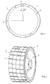
- FIG. 1 is a schematic illustration of a steel ring with permanent magnets,
- FIG. 2 is a perspective view of an exemplary rotor comprising four steel rings with permanent magnets according to a preferred embodiment of the invention,
- FIG. 3 is a perspective view illustrating the assembled stator and rotor, and
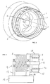
- FIG. 4 is a schematic illustration of a preferred embodiment of a machine according to the present invention.
-
- As seen in FIG. 1 and 2, the rotor according to a preferred embodiment of the invention comprises four
steel rings 1 withpermanent magnets 2 fixed on their outer surfaces. In FIG. 2, an assembled rotor system can clearly be seen which includes four steel rings having a inner side and arotor frame 3 having an outer side. However, the rotor may also be composed by two ormore rings 1 withmagnets 2. Therings 1 are made up of steel or another suitable ferromagnetic material and have the same diameter. The inner side of therings 1 is mounted on the outer side of therotor frame 3. The inner sides of therings 1 have at least oneslot 4 which serves as an alignment means and to fix the rings on therotor 3 e. g. with the help of locking means as gussets, plates or brackets. The same or similar rings can be employed for motors of different iron lengths, defining standard iron lengths as multiple values of the ring length. - As illustrated in FIG. 3, the
magnet rings 1 can be removed by the use of threadedties 5 which can be inserted intorespective holes 6 with which themagnet rings 1 are provided. In this case theties 5 are very simple tools for the successive removal of therings 1 in cooperation with saidholes 6. It is also possible to use saidties 5 to reinforce the fixation of the rings together in the axial direction. This is possible but not absolutely necessary because said fixation is achieved by theslot 4 and said gussets, plates brackets or the like which are very efficient to resist specially tangential forces. - According to FIG. 3 the
rings 1 may be delayed by an arbitrary magnet shifting angle α. This permits the generation of a skewing effect of the magnets which reduces or eliminates the cogging torque of the motor. If the magnets of two adjacent rings are positioned in the same overlapping manner as depicted in FIG. 1, the slot of the second ring is shifted with said angle α relative to theslot 4 of the first ring in front. However, by assembling the rings the first ring must be revolved around the center of the axis, i. e. shifted counterclockwise with said angle α in order to have the slots of both rings in a straight line, so that said fixing or locking means can be introduced into allslots 4 of saidrings 1. As a result, the slots of the rotor unity will be located in an overlapping manner (FIG. 2) and the magnets will be delayed by said angle α, preferable in the range of 0 < α < 3°. - FIG. 3 shows a motor having an air gap between the
magnets 2 of the rotor and a stator 7. Naturally, the stator 7 includes a stator coil. In a preferred embodiment of the invention, the circular rim or border of thesteel ring 1 exhibits a sufficient large thickness to receive thelong holes 6 for the threadedties 5 or other removing elements or tools. Theholes 6 are parallel to the axis of rotation of thering 1, i.e. perpendicular to the small flat side of the border of thering 1. - The system according to FIG. 4 includes a driving wheel 8, preferably intended to coil up a rope of an elevator or a lift installation. Said driving wheel 8 is located between two
bearings axle 11 of the rotor, and theframe 3 is fixed to saidaxle 11. Thebearing 9 may be attached to asupport 12 fixed to abase 13 located in the machine room of said elevator or lift installation. The system may include astator frame 14 supporting thebearing 10 and, with the help of connection means 15, also the stator 7. As seen in FIG. 4 theframe 3 and the stator 7 may be mounted out from thebearing 10 of the rotor. This unilateral embodiment having theframe 3 exterior to thebearing 10 facilitates the easily and quickly installation of two or more rings with permanent magnets, e. g. threerings 16 as shown in FIG. 4. - A method for mounting a permanent magnet electric machine comprising an armature 7 and an inductor or rotor with
rings magnets 2, may comprise the following method steps: - mounting the stator 7 on the
stator frame 14 over connection means 15, - mounting the
rotor frame 3 on theaxle 11 of the rotor, - mounting a
first ring 1 on saidinductor frame 3, mounting asecond ring 1 on saidinductor frame 3, fixing saidsecond ring 1 laterally on saidfirst ring 1 with the magnets of the same polarity in a predetermined alignment with the help of said alignment means 4 and locking means and mounting successively in this way allrings 1 of the inductor. For this purpose, it is also possible but not absolutely necessary to have several slots in each ring, e.g. n - 1 slots for a number n of rings. For convenience, the stator and/or the rotor may be provided with shoulders for supporting the ends of a very simple tool, preferably in the form of a jack, lifting jack, screwing jack, etc., for facilitate the introduction of the rings into theframe 3. -
- This method of assembling the rotor is not ascertainable from the finished motor, which should be dismantled in order to see how the rotor was assembled.
- One advantage of this method of construction is that during the phase of mounting the
magnets 2, it is easier to assemble small magnets on the surface of asteel ring 1 that big magnets on the surface of a rotor. It is also easier to handlesingle magnet rings 1 that an entire rotor. In addition to this, the rings can be produced separately, and they can be obtained e. g. from standard iron tubes. - Another advantage of the method according to the invention results of the fact that, for robustness reasons, it would be convenient that the length of the magnets do not exceed certain dimensions, typically 50 mm, because otherwise they become fragile. The magnet plates must not necessarily be curved. According to the invention it is no need of sticking two or more magnets of the same polarity close next to each other, as in the normal construction, what is a complex operation due to the forces between the magnets. Special tools for this purpose can be avoided. The magnetic elements may be flat elements, e.g. rare earth permanent magnets, such as neodymium-iron-boron (NdFeB), cobalt, samarium or cheap hard permanent ferrite magnets disposed with alternating magnetic polarities. Preferably, the
rings 1 are formed from a soft magnetic material such as mild steel, preferably having a relative high permeability µr >> 1. The magnets may be glued to the rings. - Another advantage of this method relates the steps of disassembling the motor. Specially for large machines located in very small spaces, when it is necessary to remove the rotor in case of failure of the stator 7 without transporting the motor, for example in large lift installations, the rings can be removed successively one at a time by inserting the threaded
ties 5 into therespective holes 6. For convenience, saidholes 6 may also be shifted in thedifferent rings 1. Once the rings are outside, the frame of the rotor can be easily removed because there are no magnetic forces between rotor an stator, and special devices to guide the rotor out of the stator, as foreseen for conventional constructions, are not needed. - Another advantage of this method is that the undesirable parasite cogging torque or ripple torque can be avoided or compensated. This effect arises from the interaction between the magnets and the teeth of the stator, which are normally straight. According to the invention, the feature of separating the magnets in several straight pieces allows obtaining a skewing effect by shifting the rings with the angle α in order to compensate said parasite torque.
- The described type of motor is of the interior-rotor machine type because the
magnets 2 are fixed on the outer surface of therings 1. According to another embodiment of the invention, the magnets can be fixed on the inner surface of the rings to give an exterior-rotor machine type. In this case, the stator stay inside. More generally speaking, the rotor with the magnets may be an inductor and the stator with the coils may be an armature. Normally the armature (stator) is fixed to a bedplate and does not move. However, there are types of machines, in which the inductor (rotor) does not move and the armature is mounted on axles as to revolve inside or outside of the inductor. The rotor may be designed for a speed of 30 to 900 rpm.
Claims (10)
- A permanent magnet electric machine comprising an armature (7) and an inductor (1, 2),
characterized in that the inductor comprises at least two rings (1) with permanent magnets (2) fixed on their outer or inner surfaces,
wherein said rings (1) are removably mounted on or constitute a removable part of an inductor frame (3)
and wherein said rings (1) are laterally fastened together by fastening means (4) in order to obtain an inductor unity. - The machine according to claim 1, wherein said rings (1) are mounted on said inductor frame (3) in such a manner that the inner side of the rings (1) is fixed on the outer side of the inductor frame (3), and wherein said magnets are fixed on the outer surface of the rings.
- The machine according to claim 1 or 2, wherein the inner side of each ring (1) has at least one slot (4) which serves to fix the rings on the rotor (3) by means of fixation or locking elements.
- The machine according to one of the claims 1 to 3, wherein the same or similar rings are employed for motors of different inductor lengths, defining standard inductor lengths in function of multiple values of the ring length.
- The machine according to one of the claims 1 to 4, wherein at least two magnet rings (1) are provided with disassembling means (6) for successively removing the rings (1) by use of corresponding disassembling tools (5).
- The machine according to one of the claims 1 to 5, wherein the rings (1) are shifted with a suitable magnet shifting angle (α) to permit the generation of a skewing effect of the magnets which reduces or eliminates a cogging torque of the motor.
- The machine according to one of the claims 1 to 6, wherein the magnets (2) are shaped in form of plates of 10 to 100 cm2, preferably curved according to the inside radius of the armature (7).
- Rotor for a machine according to one of the claims 1 to 7, wherein said inductor is a rotor having at least two rings (1) with permanent magnets (2) fixed on their working surfaces, for applications in elevator or lift installations,
wherein said rings (1) are removably mounted on or constitute a removable part of a rotor frame (3),
wherein said rings (1) are laterally fastened together by fastening means (4) in order to obtain a rotor unity, and
wherein preferably said machine is a synchronous motor. - A method for mounting a permanent magnet electric machine, comprising an armature (7) and an inductor or rotor (1, 2) having rings (1) with fixed permanent magnets (2) according to any one of the previous claims, comprising the following method steps:mounting a first ring (1) on said inductor frame (3),mounting a second ring (1) on said inductor frame (3),
fixing said second ring (1) laterally on said first ring (1) with the magnets of the same polarity in a predetermined alignment with the help of alignment and fastening means (4), andmounting successively in this way all rings (1) of the inductor. - A method for disassembling the inductor or rotor of a permanent magnet electric machine, comprising an armature (7) and an inductor or rotor (1, 2) having rings (1) with fixed permanent magnets (2) according to any one of the previous claims, comprising the following method steps:removing the rings (1) successively one at a time with the help of removing means (5, 6), and removing the frame (3) of the inductor or rotor, once the rings (1) are outside.
Priority Applications (1)
| Application Number | Priority Date | Filing Date | Title |
|---|---|---|---|
| EP02009198.9A EP1255343B1 (en) | 2001-05-04 | 2002-04-25 | Permanent magnet electric machine |
Applications Claiming Priority (3)
| Application Number | Priority Date | Filing Date | Title |
|---|---|---|---|
| EP01810440 | 2001-05-04 | ||
| EP01810440 | 2001-05-04 | ||
| EP02009198.9A EP1255343B1 (en) | 2001-05-04 | 2002-04-25 | Permanent magnet electric machine |
Publications (3)
| Publication Number | Publication Date |
|---|---|
| EP1255343A2 true EP1255343A2 (en) | 2002-11-06 |
| EP1255343A3 EP1255343A3 (en) | 2003-08-06 |
| EP1255343B1 EP1255343B1 (en) | 2013-04-24 |
Family
ID=26077372
Family Applications (1)
| Application Number | Title | Priority Date | Filing Date |
|---|---|---|---|
| EP02009198.9A Expired - Lifetime EP1255343B1 (en) | 2001-05-04 | 2002-04-25 | Permanent magnet electric machine |
Country Status (1)
| Country | Link |
|---|---|
| EP (1) | EP1255343B1 (en) |
Cited By (2)
| Publication number | Priority date | Publication date | Assignee | Title |
|---|---|---|---|---|
| WO2005093928A1 (en) * | 2004-03-25 | 2005-10-06 | Ina Drives & Mechatronics Gmbh & Co. Ohg | Rotor for a permanent-magnet synchronous motor with reduced load pulsation, and lift drive unit comprising one such motor |
| CN117277706A (en) * | 2023-11-23 | 2023-12-22 | 四川普什宁江机床有限公司 | Phase difference eliminating method for double-moment motor |
Citations (4)
| Publication number | Priority date | Publication date | Assignee | Title |
|---|---|---|---|---|
| US4877986A (en) | 1987-05-19 | 1989-10-31 | Mitsubishi Denki Kabushiki Kaisha | Rotor of magnetic generator |
| DE19501745A1 (en) | 1995-01-23 | 1996-07-25 | Egon Schmid | Method of manufacturing a motor / generator |
| JPH08331782A (en) | 1995-05-31 | 1996-12-13 | Meidensha Corp | Rotor of permanent magnet rotating electric machine |
| EP1017152A2 (en) | 1998-12-30 | 2000-07-05 | ABB Research Ltd. | Rotor for high speed permanent magnet motor |
Family Cites Families (4)
| Publication number | Priority date | Publication date | Assignee | Title |
|---|---|---|---|---|
| JPH099602A (en) * | 1995-06-21 | 1997-01-10 | Toyoda Mach Works Ltd | Stepping motor |
| IT1294422B1 (en) * | 1997-03-27 | 1999-03-24 | Motor Power Co Srl | MODULAR ELECTRIC MOTOR. |
| JPH11252835A (en) * | 1998-03-05 | 1999-09-17 | Sanyo Denki Co Ltd | Rotor of permanent magnet type rotating electric machine and high speed rotating type permanent magnet type rotating electric machine |
| US6075306A (en) * | 1998-12-30 | 2000-06-13 | Mfm Technology L.L.C. | Laminated rotor for permanent magnet brushless motors |
-
2002
- 2002-04-25 EP EP02009198.9A patent/EP1255343B1/en not_active Expired - Lifetime
Patent Citations (4)
| Publication number | Priority date | Publication date | Assignee | Title |
|---|---|---|---|---|
| US4877986A (en) | 1987-05-19 | 1989-10-31 | Mitsubishi Denki Kabushiki Kaisha | Rotor of magnetic generator |
| DE19501745A1 (en) | 1995-01-23 | 1996-07-25 | Egon Schmid | Method of manufacturing a motor / generator |
| JPH08331782A (en) | 1995-05-31 | 1996-12-13 | Meidensha Corp | Rotor of permanent magnet rotating electric machine |
| EP1017152A2 (en) | 1998-12-30 | 2000-07-05 | ABB Research Ltd. | Rotor for high speed permanent magnet motor |
Cited By (3)
| Publication number | Priority date | Publication date | Assignee | Title |
|---|---|---|---|---|
| WO2005093928A1 (en) * | 2004-03-25 | 2005-10-06 | Ina Drives & Mechatronics Gmbh & Co. Ohg | Rotor for a permanent-magnet synchronous motor with reduced load pulsation, and lift drive unit comprising one such motor |
| CN117277706A (en) * | 2023-11-23 | 2023-12-22 | 四川普什宁江机床有限公司 | Phase difference eliminating method for double-moment motor |
| CN117277706B (en) * | 2023-11-23 | 2024-02-23 | 四川普什宁江机床有限公司 | Phase difference eliminating method for double-moment motor |
Also Published As
| Publication number | Publication date |
|---|---|
| EP1255343B1 (en) | 2013-04-24 |
| EP1255343A3 (en) | 2003-08-06 |
Similar Documents
| Publication | Publication Date | Title |
|---|---|---|
| AU783957B2 (en) | Permanent magnet electric machine | |
| US6933645B1 (en) | Permanent magnet rotor and magnet cradle | |
| EP1511154A2 (en) | Fixing permanent magnets onto a rotor body | |
| CA2608470C (en) | Transverse flux electrical machine with segmented core stator | |
| EP1777795B1 (en) | Permanent magnet pole assembly | |
| EP0866540A2 (en) | A rotor for a motor or generator | |
| EP2731232B1 (en) | Generator for a wind turbine | |
| JPH07298589A (en) | Axial air gap motor | |
| WO2003058794A1 (en) | Doubly salient machine with angled permanent magnets in stator teeth | |
| US7466054B2 (en) | Aerodynamic insert for high speed permanent magnet motor | |
| US11594923B2 (en) | Rotor and motor including the same | |
| US20230052600A1 (en) | Electric machines having a radially embedded permanent magnet rotor and methods thereof | |
| US20180262081A1 (en) | Electric motor including stator assembly and method of assembly thereof | |
| EP1255343B1 (en) | Permanent magnet electric machine | |
| EP2019476A2 (en) | Electric motors | |
| US11984763B2 (en) | Electric machines having a radially embedded permanent magnet rotor and methods thereof | |
| FI117459B (en) | Procedure and mounting tools for mounting an electric machine | |
| JP2002354722A (en) | Permanent magnet synchronous machine | |
| US5929551A (en) | Rotor section containment with steel punched star | |
| KR20060058511A (en) | Brushless DC Motor | |
| JPH09182330A (en) | Synchronous rotating electric machine | |
| EP4160885B1 (en) | Rotors for electrical machines | |
| EP4329152A1 (en) | Rotor | |
| JPH1189135A (en) | Permanent magnet type motor | |
| EP4443701A1 (en) | Stator, motor, and generator |
Legal Events
| Date | Code | Title | Description |
|---|---|---|---|
| PUAI | Public reference made under article 153(3) epc to a published international application that has entered the european phase |
Free format text: ORIGINAL CODE: 0009012 |
|
| AK | Designated contracting states |
Kind code of ref document: A2 Designated state(s): AT BE CH CY DE DK ES FI FR GB GR IE IT LI LU MC NL PT SE TR |
|
| AX | Request for extension of the european patent |
Free format text: AL;LT;LV;MK;RO;SI |
|
| PUAL | Search report despatched |
Free format text: ORIGINAL CODE: 0009013 |
|
| AK | Designated contracting states |
Designated state(s): AT BE CH CY DE DK ES FI FR GB GR IE IT LI LU MC NL PT SE TR |
|
| AX | Request for extension of the european patent |
Extension state: AL LT LV MK RO SI |
|
| 17P | Request for examination filed |
Effective date: 20040123 |
|
| AKX | Designation fees paid |
Designated state(s): AT BE CH CY DE DK ES FI FR GB GR IE IT LI LU MC NL PT SE TR |
|
| 17Q | First examination report despatched |
Effective date: 20120124 |
|
| GRAP | Despatch of communication of intention to grant a patent |
Free format text: ORIGINAL CODE: EPIDOSNIGR1 |
|
| GRAS | Grant fee paid |
Free format text: ORIGINAL CODE: EPIDOSNIGR3 |
|
| GRAA | (expected) grant |
Free format text: ORIGINAL CODE: 0009210 |
|
| AK | Designated contracting states |
Kind code of ref document: B1 Designated state(s): AT BE CH CY DE DK ES FI FR GB GR IE IT LI LU MC NL PT SE TR |
|
| REG | Reference to a national code |
Ref country code: GB Ref legal event code: FG4D |
|
| REG | Reference to a national code |
Ref country code: CH Ref legal event code: EP |
|
| REG | Reference to a national code |
Ref country code: AT Ref legal event code: REF Ref document number: 609124 Country of ref document: AT Kind code of ref document: T Effective date: 20130515 |
|
| REG | Reference to a national code |
Ref country code: IE Ref legal event code: FG4D |
|
| REG | Reference to a national code |
Ref country code: DE Ref legal event code: R096 Ref document number: 60244848 Country of ref document: DE Effective date: 20130620 |
|
| REG | Reference to a national code |
Ref country code: AT Ref legal event code: MK05 Ref document number: 609124 Country of ref document: AT Kind code of ref document: T Effective date: 20130424 |
|
| REG | Reference to a national code |
Ref country code: NL Ref legal event code: VDEP Effective date: 20130424 |
|
| PG25 | Lapsed in a contracting state [announced via postgrant information from national office to epo] |
Ref country code: FI Free format text: LAPSE BECAUSE OF FAILURE TO SUBMIT A TRANSLATION OF THE DESCRIPTION OR TO PAY THE FEE WITHIN THE PRESCRIBED TIME-LIMIT Effective date: 20130424 Ref country code: PT Free format text: LAPSE BECAUSE OF FAILURE TO SUBMIT A TRANSLATION OF THE DESCRIPTION OR TO PAY THE FEE WITHIN THE PRESCRIBED TIME-LIMIT Effective date: 20130826 Ref country code: BE Free format text: LAPSE BECAUSE OF FAILURE TO SUBMIT A TRANSLATION OF THE DESCRIPTION OR TO PAY THE FEE WITHIN THE PRESCRIBED TIME-LIMIT Effective date: 20130424 Ref country code: SE Free format text: LAPSE BECAUSE OF FAILURE TO SUBMIT A TRANSLATION OF THE DESCRIPTION OR TO PAY THE FEE WITHIN THE PRESCRIBED TIME-LIMIT Effective date: 20130424 Ref country code: GR Free format text: LAPSE BECAUSE OF FAILURE TO SUBMIT A TRANSLATION OF THE DESCRIPTION OR TO PAY THE FEE WITHIN THE PRESCRIBED TIME-LIMIT Effective date: 20130725 Ref country code: ES Free format text: LAPSE BECAUSE OF FAILURE TO SUBMIT A TRANSLATION OF THE DESCRIPTION OR TO PAY THE FEE WITHIN THE PRESCRIBED TIME-LIMIT Effective date: 20130804 Ref country code: AT Free format text: LAPSE BECAUSE OF FAILURE TO SUBMIT A TRANSLATION OF THE DESCRIPTION OR TO PAY THE FEE WITHIN THE PRESCRIBED TIME-LIMIT Effective date: 20130424 |
|
| PG25 | Lapsed in a contracting state [announced via postgrant information from national office to epo] |
Ref country code: CY Free format text: LAPSE BECAUSE OF FAILURE TO SUBMIT A TRANSLATION OF THE DESCRIPTION OR TO PAY THE FEE WITHIN THE PRESCRIBED TIME-LIMIT Effective date: 20130424 |
|
| REG | Reference to a national code |
Ref country code: IE Ref legal event code: MM4A |
|
| PG25 | Lapsed in a contracting state [announced via postgrant information from national office to epo] |
Ref country code: DK Free format text: LAPSE BECAUSE OF FAILURE TO SUBMIT A TRANSLATION OF THE DESCRIPTION OR TO PAY THE FEE WITHIN THE PRESCRIBED TIME-LIMIT Effective date: 20130424 Ref country code: MC Free format text: LAPSE BECAUSE OF FAILURE TO SUBMIT A TRANSLATION OF THE DESCRIPTION OR TO PAY THE FEE WITHIN THE PRESCRIBED TIME-LIMIT Effective date: 20130424 |
|
| PG25 | Lapsed in a contracting state [announced via postgrant information from national office to epo] |
Ref country code: IT Free format text: LAPSE BECAUSE OF FAILURE TO SUBMIT A TRANSLATION OF THE DESCRIPTION OR TO PAY THE FEE WITHIN THE PRESCRIBED TIME-LIMIT Effective date: 20130424 Ref country code: NL Free format text: LAPSE BECAUSE OF FAILURE TO SUBMIT A TRANSLATION OF THE DESCRIPTION OR TO PAY THE FEE WITHIN THE PRESCRIBED TIME-LIMIT Effective date: 20130424 |
|
| PLBE | No opposition filed within time limit |
Free format text: ORIGINAL CODE: 0009261 |
|
| STAA | Information on the status of an ep patent application or granted ep patent |
Free format text: STATUS: NO OPPOSITION FILED WITHIN TIME LIMIT |
|
| 26N | No opposition filed |
Effective date: 20140127 |
|
| REG | Reference to a national code |
Ref country code: FR Ref legal event code: ST Effective date: 20140228 |
|
| PG25 | Lapsed in a contracting state [announced via postgrant information from national office to epo] |
Ref country code: IE Free format text: LAPSE BECAUSE OF NON-PAYMENT OF DUE FEES Effective date: 20130425 |
|
| REG | Reference to a national code |
Ref country code: DE Ref legal event code: R097 Ref document number: 60244848 Country of ref document: DE Effective date: 20140127 |
|
| PG25 | Lapsed in a contracting state [announced via postgrant information from national office to epo] |
Ref country code: FR Free format text: LAPSE BECAUSE OF NON-PAYMENT OF DUE FEES Effective date: 20130624 |
|
| PG25 | Lapsed in a contracting state [announced via postgrant information from national office to epo] |
Ref country code: TR Free format text: LAPSE BECAUSE OF FAILURE TO SUBMIT A TRANSLATION OF THE DESCRIPTION OR TO PAY THE FEE WITHIN THE PRESCRIBED TIME-LIMIT Effective date: 20130424 |
|
| PG25 | Lapsed in a contracting state [announced via postgrant information from national office to epo] |
Ref country code: LU Free format text: LAPSE BECAUSE OF NON-PAYMENT OF DUE FEES Effective date: 20130425 |
|
| PGFP | Annual fee paid to national office [announced via postgrant information from national office to epo] |
Ref country code: CH Payment date: 20150428 Year of fee payment: 14 Ref country code: GB Payment date: 20150420 Year of fee payment: 14 |
|
| REG | Reference to a national code |
Ref country code: CH Ref legal event code: PL |
|
| GBPC | Gb: european patent ceased through non-payment of renewal fee |
Effective date: 20160425 |
|
| PG25 | Lapsed in a contracting state [announced via postgrant information from national office to epo] |
Ref country code: LI Free format text: LAPSE BECAUSE OF NON-PAYMENT OF DUE FEES Effective date: 20160430 Ref country code: GB Free format text: LAPSE BECAUSE OF NON-PAYMENT OF DUE FEES Effective date: 20160425 Ref country code: CH Free format text: LAPSE BECAUSE OF NON-PAYMENT OF DUE FEES Effective date: 20160430 |
|
| PGFP | Annual fee paid to national office [announced via postgrant information from national office to epo] |
Ref country code: DE Payment date: 20210628 Year of fee payment: 20 |
|
| REG | Reference to a national code |
Ref country code: DE Ref legal event code: R071 Ref document number: 60244848 Country of ref document: DE |