EP1826636A1 - Appareil horaire multifonction comprenant une pluralite de types de trains de roues a deplacement d`aiguille - Google Patents
Appareil horaire multifonction comprenant une pluralite de types de trains de roues a deplacement d`aiguille Download PDFInfo
- Publication number
- EP1826636A1 EP1826636A1 EP04807087A EP04807087A EP1826636A1 EP 1826636 A1 EP1826636 A1 EP 1826636A1 EP 04807087 A EP04807087 A EP 04807087A EP 04807087 A EP04807087 A EP 04807087A EP 1826636 A1 EP1826636 A1 EP 1826636A1
- Authority
- EP
- European Patent Office
- Prior art keywords
- wheel
- rotation center
- train wheel
- main plate
- day
- Prior art date
- Legal status (The legal status is an assumption and is not a legal conclusion. Google has not performed a legal analysis and makes no representation as to the accuracy of the status listed.)
- Granted
Links
- 238000004804 winding Methods 0.000 claims description 78
- 230000005540 biological transmission Effects 0.000 description 268
- 239000013078 crystal Substances 0.000 description 10
- 239000010437 gem Substances 0.000 description 8
- 229910001751 gemstone Inorganic materials 0.000 description 7
- 239000011521 glass Substances 0.000 description 5
- 229910001220 stainless steel Inorganic materials 0.000 description 5
- 239000010935 stainless steel Substances 0.000 description 5
- 230000010355 oscillation Effects 0.000 description 4
- 230000002093 peripheral effect Effects 0.000 description 4
- 229910000906 Bronze Inorganic materials 0.000 description 3
- OAICVXFJPJFONN-UHFFFAOYSA-N Phosphorus Chemical compound [P] OAICVXFJPJFONN-UHFFFAOYSA-N 0.000 description 3
- 239000010974 bronze Substances 0.000 description 3
- KUNSUQLRTQLHQQ-UHFFFAOYSA-N copper tin Chemical compound [Cu].[Sn] KUNSUQLRTQLHQQ-UHFFFAOYSA-N 0.000 description 3
- 239000013013 elastic material Substances 0.000 description 3
- 210000000078 claw Anatomy 0.000 description 2
- 239000000470 constituent Substances 0.000 description 2
- 239000000463 material Substances 0.000 description 2
- 229910001369 Brass Inorganic materials 0.000 description 1
- PEDCQBHIVMGVHV-UHFFFAOYSA-N Glycerine Chemical compound OCC(O)CO PEDCQBHIVMGVHV-UHFFFAOYSA-N 0.000 description 1
- 239000011324 bead Substances 0.000 description 1
- 239000010951 brass Substances 0.000 description 1
- 229920006351 engineering plastic Polymers 0.000 description 1
- 238000004519 manufacturing process Methods 0.000 description 1
- 239000002184 metal Substances 0.000 description 1
- 229920002492 poly(sulfone) Polymers 0.000 description 1
- 239000004417 polycarbonate Substances 0.000 description 1
- 229920000515 polycarbonate Polymers 0.000 description 1
Images


Classifications
-
- G—PHYSICS
- G04—HOROLOGY
- G04C—ELECTROMECHANICAL CLOCKS OR WATCHES
- G04C3/00—Electromechanical clocks or watches independent of other time-pieces and in which the movement is maintained by electric means
- G04C3/008—Mounting, assembling of components
-
- G—PHYSICS
- G04—HOROLOGY
- G04B—MECHANICALLY-DRIVEN CLOCKS OR WATCHES; MECHANICAL PARTS OF CLOCKS OR WATCHES IN GENERAL; TIME PIECES USING THE POSITION OF THE SUN, MOON OR STARS
- G04B19/00—Indicating the time by visual means
- G04B19/24—Clocks or watches with date or week-day indicators, i.e. calendar clocks or watches; Clockwork calendars
- G04B19/241—Clocks or watches with date or week-day indicators, i.e. calendar clocks or watches; Clockwork calendars the date is indicated by one or more hands
-
- G—PHYSICS
- G04—HOROLOGY
- G04C—ELECTROMECHANICAL CLOCKS OR WATCHES
- G04C17/00—Indicating the time optically by electric means
Definitions
- the present invention relates to a multifunction timepiece including plural types of hand operating train wheels.
- the invention relates to an analog multifunction timepiece including plural types of hand operating train wheels constituted to be able to realize plural movement layouts by only changing a position of integrating a part without changing a dimension and a shape of the part of a movement.
- a machine body including a portion of driving a timepiece is referred to as "movement".
- a state in which the movement is attached with a dial, a hand and put into a timepiece case to constitute a finished product is referred to as "complete" of a timepiece.
- a side including glass of a timepiece case that is, a side of including a dial
- back side or "glass side” or "dial side” of a movement.
- a side of including a case back of a timepiece case that is, a side opposed to a dial is referred to as "top side” or "case back side” of a movement.
- a train wheel integrated to "top side” of a movement is referred to as “top train wheel”.
- a train wheel integrated to "back side” of a movement is referred to as “back train wheel”.
- “12 o'clock side” indicates a side of arranging a graduation in correspondence with 12 o'clock of a dial in an analog timepiece.
- “12 o'clock direction” indicates a direction directed to "12 o'clock side” from a center of a main plate or a rotation center of an indicator of an hour hand or the like (hereinafter, referred to as "main plate center”) in an analog type timepiece.
- main plate center a rotation center of an indicator of an hour hand or the like
- “2 o'clock side” indicates a side of arranging a graduation in correspondence with 2 o'clock of a dial in an analog type timepiece.
- “2 o'clock direction” indicates a direction directed to "2 o'clock side” from a main plate center in an analog type timepiece.
- "3 o'clock side” indicates a side of arranging a graduation in correspondence with 3 o'clock of a dial in an analog timepiece.
- “3 o' clock direction” indicates a direction directed to "3 o'clock side” from a main plate center in an analog type timepiece.
- “6 o'clock side” indicates a side of arranging a graduation in correspondence with 6 o'clock of a dial in an analog type timepiece.
- “6 o'clock direction” indicates a direction directed to "6 o'clock side” from a main plate center in an analog type timepiece.
- “9 o' clock side” indicates a side of arranging a graduation in correspondence with 9 o'clock of a dial in an analog type timepiece.
- "9 o'clock direction” indicates a direction directed to "9 o'clock side” from a main plate center in an analog type timepiece.
- “10 o'clock side” indicates a side of arranging a graduation in correspondence with 10 o'clock of a dial in an analog type timepiece.
- “10 o'clock direction” indicates a direction directed to "10 o' clock side” from a main plate center in an analog type timepiece. Further, there is a case of indicating a side of arranging other graduation of a dial as in “4 o'clock direction", "4 o'clock side”.
- a date star wheel and a small day wheel are arranged at positions substantially symmetrical with each other relative to a timepiece center.
- a small date hand constituting a kind of a small hand is attached to the date star wheel.
- a small day hand constituting a kind of a small hand is attached to the small day wheel (refer to, for example, Patent Reference 1).
- a date star wheel and a small day wheel are arranged at positions substantially symmetrical with each other relative to a timepiece center, and a date indicator driving wheel, a day indicator driving wheel respectively include both of a date feed finger, a day feed finger (refer to, for example, Patent Reference 2).
- a main plate includes a train wheel rotation center of a rotor and a train wheel used in fabricating "center chronograph timepiece”, and a train wheel rotation center of a rotor and a train wheel used in fabricating "side chronograph timepiece”
- a bridge member includes a train wheel rotation center of the rotor and the train wheel used in fabricating "center chronograph timepiece”, and a train wheel rotation center of the rotor and the train wheel used in fabricating "side chronograph timepiece”
- the rotor and the train wheel used in fabricating "side chronograph timepiece” including a chronograph hand constituting a kind of a small hand are integrated rotatably relative to the train wheel rotation center of the main plate and the train wheel rotation center of the bridge member (refer to, for example, Patent Reference 3).
- a fourth type of multifunction timepiece including a small hand of a background art
- "12 o'clock side” is arranged with a small hand rotated by 360 degrees
- "3 o'clock side” and “9 o' clock side” are respectively arranged with small hands operated in a fan shape
- "6 o'clock side” is arranged with a circular disk for indicating a moon phase.
- the small hand operated in the fan shape is attached to an indicator wheel provided with a hairspring (refer to, for example, Patent Reference 4).
- the multifunction timepiece including the small hand of the background art in the movement, when a position of a rotation center of a wheel for attaching a small hand (small indicating hand) of the date star wheel, the small day wheel, the chronograph wheel or the like is changed, a plurality of parts related thereto need to be changed. Therefore, when a plurality of movement layouts including small hands are formed, it is necessary to separately design the respective movements and prepare a number of working machines, dies and the like for working constituent parts of the respective movements. Therefore, in fabricating the multifunction timepiece including the small hand of the background art, there poses a problem that much time period is needed for switching part working operations, further, a number of part fabricating steps is increased.
- an analog multifunction timepiece including a small hand constituted to be able to constitute a plurality of types of hand operating train wheels by only changing positions of integrating parts without changing dimensions and shapes of the parts of a movement when a position of a rotation center of a wheel for attaching a small hand is changed. Further, it is other object of the invention to realize an analog multifunction timepiece including a small hand having a small number of part fabricating steps without needing much time period for switching part working operations.
- the invention is a multifunction timepiece including a main plate constituting a base plate of a movement, a winding stem for correcting an indication, a switching mechanism for switching a position of the winding stem, a dial for indicating time information, and a small hand for indicating the time information or calendar information constituted such that the movement includes a first train wheel rotation center for a train wheel used in fabricating a first type of the multifunction timepiece having an arrangement of a first type of the small hand by using the movement, and a second train wheel rotation center for a train wheel used in fabricating a second type of the multifunction timepiece having an arrangement of a second type of the small hand by using the movement.
- the first train wheel rotation center is provided with a train wheel guide portion for guiding a train wheel member rotated to move centering on a position thereof to be able to rotate to move
- the second train wheel rotation center is provided with a train wheel guide portion for guiding a train wheel member moved in a fan shape centering on a position thereof.
- the train wheel rotation center of the train wheel member rotated to move is arranged at a position between a main plate center of the main plate and a main plate outer shape portion of the main plate.
- the train wheel rotation center of the train wheel member moved in the fan shape is arranged at a position between the main plate center of the main plate and the main plate outer shape portion of the main plate.
- a train wheel for indicating the calendar information is arranged rotatably relative to the first train wheel rotation center or the second train wheel rotation center.
- the multifunction timepiece is constituted such that when the train wheel for indicating the calendar information is arranged at the first train wheel rotation center, the calendar information is made to be able to indicate by the small hand rotated to move by the train wheel, and when the fan shape hand operating train wheel for indicating the calendar information is arranged at the second train wheel rotation center, the calendar information is made to be able to indicate by the small hand moved in the fan shape by the fan shape hand operating train wheel.
- the multifunction timepiece is constituted such that the time information or the calendar information is indicated by the small hand rotated by constituting the rotation center by the position between the main plate center and the outer shape portion of the main plate.
- a distance between the rotation center of the train wheel member moved in the fan shape and the main plate center of the main plate is constituted to be larger than a distance between the rotation center of the train wheel member rotated to move and the main plate center of the main plate.
- the calendar information can be indicated to be easy to see by the small hand operated in the fan shape.
- the multifunction timepiece of the invention can be constituted such that the first train wheel rotation center is arranged in a 9 o' clock direction of the movement, and the second train wheel rotation center is arranged in the 9 o'clock direction of the movement.
- the multifunction timepiece of the invention can be constituted such that the movement further includes a third train wheel rotation center for a train wheel used in fabricating the multifunction timepiece having an arrangement of a small hand, the third train wheel rotation center is arranged at a position between the main plate center of the main plate and the main plate outer shape portion of the main plate, at the third train wheel rotation center, a train wheel guide portion for rotatably guiding a train wheel member rotated centering on a position thereof is provided, a train wheel for indicating the time information or the calendar information is arranged to be able to rotate relative to the third train wheel rotation center and the time information or the calendar information is constituted to indicate by the further small hand.
- the multifunction timepiece capable of realizing the multifunction timepiece further including the small hand.
- the third train wheel rotation center can be arranged in a 6 o' clock direction of the movement. Or, the third train wheel rotation center can be arranged in a 12 o' clock direction of the movement. Or, the third train wheel rotation center can be arranged in a 3 o'clock direction of the movement.
- the multifunction timepiece capable of realizing various movement layouts.
- the movement includes a day indicator driving wheel rotated based on a rotation of an hour wheel
- the day indicator driving wheel is constituted to be able to rotate a train wheel member rotated to move when the train wheel member rotated to move is arranged at the first train wheel rotation center, and is constituted to be able to move in the fan shape the train wheel member moved in the fan shape when a train wheel member moved in the fan shape is arranged at the second train wheel rotation center.
- a plurality of movement layouts including pluralities of types of hand operating train wheels can be formed by only changing the position of integrating the part without changing the dimension and the shape of the part of the movement. Further, the multifunction timepiece of the invention does not need much time period in switching the part working operations, and therefore, the number of part fabricating steps of the multifunction timepiece can be reduced.
- a movement is constituted by an analog electronic timepiece.
- the first embodiment of the multifunction timepiece of the invention is constituted by an analog type timepiece (electric timepiece, electronic timepiece, mechanical type timepiece) including a small hand at at least one portion in "3 o'clock direction", “6 o'clock direction”, “9 o'clock direction”, "12 o'clock direction”.
- the multifunction timepiece of the invention there can be constructed a constitution in which by an hour hand a rotation center of which is a center of a main plate, time information with regard to "hour” of a 12 hour system is indicated, by a minute hand a rotation center of which is the center of the main plate, time information with regard to "minute” is indicated, by a 24 hour hand a rotation center of which is arranged in "12 o'clock direction”, time information with regard to "hour” of a 24 hour system is indicated, by a date hand a rotation center of which is arranged in "3 o' clock direction”, calendar information with regard to "date” is indicated, by a small second hand a rotation center of which is arranged in "6 o'clock direction”, time information with regard to "second” is indicated, by a day hand a rotation center of which is arranged in "9 o'clock direction”, calendar information with regard to "day” is indicated.
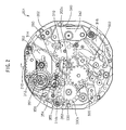
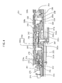
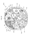
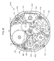
- a movement 201 includes a main plate 202.
- a power source portion, a circuit portion, a converter (step motor), a top train wheel, a switching mechanism and the like are arranged on a case back side (top side) of the main plate 202.
- a back train wheel, a calendar train wheel, a date correcting mechanism and the like are arranged on a back side of the main plate 202.
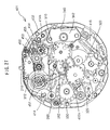
- a dial 204 is arranged on a glass side of the main plate 202.
- a winding stem 210 is arranged rotatably on 3 o'clock side of the main plate 202.
- a battery 202 constituting a power source of the multifunction timepiece is arranged on a case back side of the main plate 202.
- a crystal unit 222 constituting an oscillation source of the timepiece is arranged on the case back side of the main plate 202.
- a crystal oscillator oscillated by 32, 768 Hertz is contained in the crystal unit 222.
- a lead portion of the crystal unit 222 is fixed to a printed circuit board 224.
- a battery connector(+) 226 is arranged to conduct an anode of the battery 220 and a plus pattern of the printed circuit board 224.
- a battery connector(-) 228 is arranged to conduct the anode of the battery 220 and a minus pattern of the printed circuit board 224.
- the multifunction timepiece of the invention can also be constituted by a timepiece having a reference signal generating source (oscillation source) other than the crystal unit.
- An oscillating portion (oscillator) for outputting a reference signal based on oscillation of the crystal oscillator, a dividing portion (divider) for dividing an output signal of the oscillating portion, a driving portion (driver) for outputting a motor drive signal for driving the step motor based on an output signal of the dividing portion are included in an integrated circuit (IC) 230.
- the integrated circuit (IC) 230 is constituted by, for example, C-MOS or PLA.
- the integrated circuit (IC) 230 is constituted by C-MOS
- the oscillating portion, the dividing portion, and the driving portion are included in the integrated circuit 230.
- the integrated (IC) 230 is constituted by PLA
- the oscillating portion, the dividing portion, the driving portion are constituted to be operated by a program stored to PLA.
- the integrated circuit 230 is fixed to the printed circuit board 224.
- the printed circuit board 224, the crystal unit 222, and the integrated circuit 230 constitute a circuit block.
- a coil block 232 including a coil wire wound around a magnetic core, a stator 234 arranged to be brought into contact with both end portions of the magnetic core of the coil block 232, and a rotor 236 including a rotor magnet arranged at a rotor hole of the stator 234 are arranged on the case back side of the main plate 202.
- the coil block 232, the stator 234, and the rotor 236 constitute the step motor.
- a fifth wheel & pinion 238 rotated based on rotation of the rotor 236 is arranged on the case back side of the main plate 202.
- the fifth wheel & pinion 238 includes a fifth wheel 238b, a fifth upper pinion 238c, a fifth lower pinion 238d.
- the rotor pinion is constituted to be brought in mesh with the fifth wheel 238b.
- a fourth wheel & pinion 240 rotated based on rotation of the fifth wheel & pinion 238 is arranged on the case back side of the main plate 202.
- a fifth pinion is constituted to be brought in mesh with a fourth wheel.
- a third wheel & pinion 242 rotated based on rotation of the fourth wheel & pinion 240 is arranged on the case back side of the main plate 202.
- a fourth pinion is constituted to be brought in mesh with a third wheel.
- a center wheel & pinion 244 rotated based on rotation of the third wheel & pinion 242 is arranged on the case bask side of the main plate 202.
- the center wheel & pinion 244 includes a center wheel 244b and a center pinion 244c.
- a third pinion is constituted to be brought in mesh with the second wheel 244b.
- a slip mechanism is provided between the center wheel 244b and the center pinion 244c. By providing the slip mechanism, when hands are set, a minute hand and an hour hand can be rotated by rotating the winding stem 210 in a state of stopping to rotate the top train wheel.
- a minute hand 244h is attached to the center wheel & pinion 244.
- a train wheel setting lever 250 is arranged on the case back side of the main plate 202 for setting the fourth wheel & pinion 240 when hands are set by pulling the winding stem 210 to a second stage.
- a reset lever 252 is arranged on the case back side of the main plate 202 to reset operation of the integrated circuit 230 when hands are set by pulling the winding stem 210 to the second stage.
- a train wheel bridge 256 supports an upper shaft portion of the rotor 236, an upper shaft portion of the fifth wheel & pinion 238, an upper shaft portion of the fourth wheel & pinion 240, an upper shaft portion of the third wheel & pinion 242, an upper shaft portion of the center wheel & pinion 244 respectively rotatably.
- the main plate 202 supports a lower shaft portion of the rotor 236, a lower shaft portion of the fifth wheel & pinion 238, a lower shaft portion of the fourth wheel & pinion 240, a lower shaft portion of the third wheel & pinion 242, respectively rotatably.
- a center pipe 202b is arranged at the main plate center 202c of the main plate 202.
- An abacus bead portion of the center wheel & pinion 244 is rotatably supported by an inner diameter portion of a center hole of the center pipe 202b.
- a rotation center of the center wheel & pinion 244 is arranged at the main plate center 202c.
- the center wheel & pinion 244 is constituted to rotate by one rotation in one hour.
- a minute wheel 260 rotated based on rotation of the center wheel & pinion 244 is arranged on the case back side of the main plate 202.
- the center pinion 244c is constituted to be brought in mesh with the minute wheel.
- An hour wheel & pinion 262 is constituted to rotate based on rotation of the minute wheel 260.
- the hour wheel & pinion 262 is arranged on the dial side of the main plate 202.
- the hour wheel & pinion 262 includes an hour wheel 262b and a date indicator driving pinion 262c.
- a center wheel of the minute wheel & pinion 262 is arranged to be rotatable relative to an outer peripheral portion of a cylinder portion of the center pipe 202b.
- the minute pinion is constituted to be brought in mesh with the hour wheel 262b of the hour wheel& pinion 262.
- the hour wheel & pinion 262 is constituted to rotate by one rotation in 12 hours.
- An hour hand 262h is attached to the hour wheel & pinion 262.
- a rotation center of the hour wheel & pinion 262 is arranged at the main plate center 202c.
- the switching mechanism is arranged on the case back side of the main plate 202.
- the switching mechanism is arranged at "3-6 o'clock region".
- the switching mechanism can also be arranged on the dial side of the main plate 202.
- the switching mechanism, a time setting mechanism, a calendar correcting mechanism are provided for correcting indication of a calendar by setting time of the timepiece by rotating the winding stem 210 in a state of pulling out the winding stem 210.
- the switching mechanism is constituted to include a setting lever 270, a yoke 272.
- the setting lever 270, the yoke 272 are supported to be operable relative to the main plate 202.
- the yoke 272 is constituted to include a yoke spring portion at one tail portion.
- the time setting mechanism includes the winding stem 210 and a clutch wheel 274.
- the winding stem 210 includes a front end shaft portion, a square shaft portion, a first date corrector setting transmission wheel guide portion, a setting lever inner wall portion, a setting lever receiving portion, a setting lever outer wall portion, an outer side shaft portion and the like formed successively from a front end portion to an outer portion.
- the front end shaft portion of the winding stem 210 is rotatably supported by a winding stem front end guide hole of the main plate 202.
- An outer side portion of the setting lever outer wall portion of the winding stem 210 is rotatably supported by a winding stem outer side shaft guide hole.
- the switching mechanism may be constituted to include the setting lever, the yoke, a yoke holder (not illustrated).
- the position of the setting lever in the rotational direction can be determined by providing a switch spring portion at the yoke holder, providing a switch pin portion at the setting lever, providing a mountain shape portion at a front end of the switch pin portion, bringing the mountain shape portion having an elastic force into contact with the switch pin portion.
- a square hole portion of the clutch wheel 274 is integrated to the square shaft portion of the winding stem 210.
- the portion of the setting lever 270 brought into contact with the winding stem is disposed between the setting lever inner wall portion, and the setting lever outer wall portion of the winding stem 210.
- a position of the winding stem 210 in a direction along a center axis line of the winding stem 210 is determined by the setting lever 270, and the yoke 272.
- a position of the clutch wheel 274 in the direction along the center axis line of the winding stem 210 is determined by the yoke 272.
- the clutch wheel 274 includes an A tooth 274a disposed on a side proximate to a center portion of the movement 201.
- a center hole portion of a first date corrector setting transmission wheel 351 is rotatably integrated to the first date corrector setting transmission wheel guide portion of the winding stem.
- the first date corrector setting transmission wheel 351 is constituted to be able to be brought in mesh with a second date corrector setting transmission wheel 352.
- a setting wheel 278 is arranged on the case back side of the main plate 202.
- the setting wheel 278 is rotatably supported by a setting wheel pin of the main plate 202.
- the minute wheel 260 is constituted to rotate by rotating the setting wheel 278.
- a date indicator feed mechanism is operated based on rotation of the hour wheel 262.
- the date indicating mechanism includes a date indicator driving wheel 310 and a date star wheel 312. There is constructed a constitution in which by rotating the hour wheel 262, the date indicator driving wheel 310 is rotated.
- the date indicator driving wheel 310 is rotatably supported by a date indicator driving wheel pin provided at the main plate 202. It is preferable that a rotation center of the date indictor driving wheel 310 is arranged at a region between "5 o'clock direction" and "6 o'clock direction" (that is, "5-6 o'clock region).
- the date indicator driving wheel 310 includes a date indicator driving tooth 310b and a date indicator driving finger 310f. There is constructed a constitution in which a date indicator driving pinion 262c of the hour wheel 262 is brought in mesh with the date indicator driving tooth 310b of the date indicator driving wheel 310. There is constructed a constitution in which by the date indicator driving finger 310f provided at the date indicator driving wheel 310, the date star wheel 312 is rotated once per 1 day (1/31) . The date star wheel 312 is constituted to rotate by one rotation per 31 days. A wheel portion of the date star wheel 312 includes 31 pieces of teeth. A position in a rotational direction of the date star wheel 312 is set by a date jumper 316b provided at a setting lever jumper 316.
- a setting portion provided at a front end of a spring portion of the date jumper 316b in a region between "2 o'clock direction” and "3 o'clock direction” (that is, “2-3 o'clock region”).
- a rotation center of the date star wheel 312 is arranged in "3 o'clock direction". Therefore, the rotation center of the date star wheel 312 is arranged on the center axis line of the winding stem 210.
- a lower shaft portion of the date star wheel 312 is rotatably supported by the main plate 202.
- a portion of a date corrector setting transmission wheel holder 314 disposed on a lower side of the date star wheel 312 is narrowed in a circular shape to a back face of the main plate 202. It is preferable that a hole provided at a center of the circular shape narrowing portion of the date corrector setting transmission wheel holder 314 is fitted to a date corrector setting transmission wheel holder guide shaft portion provided at a surrounding of a date star wheel guide hole.
- a date hand 312h is attached to an upper shaft portion of the date star wheel 312.
- a wheel portion of the date star wheel 312 is arranged between the date corrector setting transmission wheel holder 314 and the setting lever jumper 316 disposed on the dial side of the main plate 202.
- a character, a numeral, an abbreviated character or the like for indicating date is provided at the dial 204.
- a day wheel feed mechanism is constituted to operate based on rotation of the hour wheel 262.
- the day indicating mechanism includes a day indicator driving wheel 320, a small day wheel 322.
- the day indicator driving wheel 320 is constituted to rotate.
- the day indicator driving wheel 320 is rotatably supported by a day indicator driving wheel pin provided at the main plate 202. It is preferable to arrange a rotation center of the day indicator driving wheel 320 at a region between "10 o'clock direction" and "11 o'clock direction" (that is, "10-11 o'clock region").
- the day indicator driving wheel 320 includes a day indicator driving tooth 320b and a day feed finger 320f.
- the day indicator driving wheel finger 262c of the hour wheel 262 is constituted to be brought in mesh with the day indicator driving wheel tooth 320b of the day indicator driving wheel 320.
- the small day wheel 322 is constituted to rotate once per one day (1/7) .
- a wheel portion of the small day wheel 322 includes 7 pieces of teeth.
- the small day wheel 322 is constituted to rotate by one rotation per 7 days.
- a position in a rotational direction of the small day wheel 322 is set by a day jumper 316c provided at the setting lever jumper 316.
- a setting portion provided at a front end of a spring portion of the day jumper 316c in a region between "8 o'clock direction” and "9 o'clock direction” (that is, “8-9 o'clock region”).
- a rotation center of the small day wheel 322 is arranged in "9 o'clock direction". Therefore, the rotation center of the small day wheel 322 is arranged on an extension of the center axis line of the winding stem 210.
- a lower shaft portion of the small day wheel 322 is rotatably-supported by the main plate 202.
- a day hand 322h is attached to an upper shaft portion of the small day wheel 322.
- a wheel portion of the small day wheel 322 is arranged between the main plate 202 and the setting lever jumper 316.
- a day character, a numeral, an abbreviated character or the like for indicating day is provided at the dial 204. There is constructed a constitution in which by the day hand 322h, a character, a numeral, an abbreviated character or the like, information with regard to "day" constituting one of calendar information can be indicated.
- the 24 hour indicating mechanism is constituted to operate based on rotation of the day indicator driving wheel 320.
- the 24 hour indicating mechanism includes an hour indicator 330.
- the hour indicator 330 is constituted to rotate by way of rotation of the day indicator driving wheel 320.
- a lower shaft portion provided at the hour indicator 330 is rotatably supported by an hour indicator guide hole provided at the main plate 202. It is preferable to arrange a rotation center of the hour indicator 330 in "12 o'clock direction".
- the day indicator driving gear 320b provided at the day indicator driving wheel 320 is constituted to be brought in mesh with a tooth portion 330b of the hour indicator 330.
- the hour indicator 330 is constituted to rotate by one rotation in 24 hours.
- a wheel portion of the hour indicator 330 is arranged between the main plate 202 and the setting lever jumper 316.
- a 24 hour hand (not illustrated: mentioned later) is attached to an upper shaft portion of the day indicator 330.
- a character, a numeral, an abbreviated character or the like for indicating "hour” is provided at the dial 204 in a style of constituting 24 hours by one turn (referred to as "24 hour system").
- 24 hour system There is constructed a constitution in which by a 24 hour hand and a numeral or the like, information with regard to "hour” constituting time information can be indicated.
- the second indicating mechanism includes a second indicator 340.
- a wheel portion of the second indicator 340 is constituted to be brought in mesh with the fifth lower pinion 238d.
- a lower shaft portion of the second indicator 340 is rotatably supported by the main plate 302.
- An upper shaft portion of the second indicator 340 is rotatably supported by a second indicator bridge 342.
- the second indicator bridge 342 it is preferable to arrange the second indicator bridge 342 so as not to overlap the date indicator driving wheel 310. It is preferable to arrange a rotation center of the second indicator 340 in "6 o' clock direction".
- the second indicator 340 is constituted to rotate by one rotation in 1 minute.
- a wheel portion of the second indicator 340 is arranged between the main plate 202 and the second indicator bridge 342.
- a small second hand (not illustrated: mentioned later) is attached to a front end portion of an upper shaft portion of the second indicator 340.
- a character, a numeral, an abbreviated character or the like for indicating "second” is provided at the dial 204. There is constructed a constitution in which by a small second hand and a numeral or the like, information with regard to "second" constituting time information can be indicated.
- the first embodiment of the invention includes a date star wheel 312 a rotation center of which is arranged in "3 o'clock direction”, a small day wheel 322 a rotation center of which is arranged in "9 o' clock direction”, the second indicator 340 the rotation center of which is arranged in "6 o' clock direction”, and the hour indicator 330 the rotation center of which is arranged in "12 o'clock direction”.
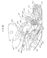
- a back side of the movement 201 is provided with the date correcting mechanism for correcting indication of date by the date star wheel 312.
- the date correcting mechanism is constituted by a first corrector setting transmission wheel 351, the second corrector setting transmission wheel 352, a third corrector setting transmission wheel 353, a fourth corrector setting transmission wheel 354, a date corrector setting wheel 355.
- the first corrector setting transmission wheel 351 is rotatably supported by a first corrector setting transmission wheel guide portion of the winding stem 210.
- the first corrector setting transmission wheel 351 and the winding stem 210 are arranged to be coaxial with each other.
- the second corrector setting transmission wheel 352 is rotatably supported by the main plate 202.
- a wheel portion of the second corrector setting transmission wheel 352 is arranged between the main plate 202 and the date corrector setting wheel holder 314.
- a rotation center of the second corrector setting transmission wheel 352 is arranged in "3 o'clock direction". Therefore, the rotation center of the second corrector setting transmission wheel 352 is arranged on the center axis line of the winding stem 210. It is preferable to arrange the rotation center of the second corrector setting transmission wheel 352 at a position the same as that of the rotation center of the date star wheel 312.
- the third corrector setting transmission wheel 353 is rotatably supported by the main plate 202.
- a wheel portion of the third corrector setting transmission wheel 353 is arranged between the main plate 202 and the date corrector setting wheel holder 314. It is preferable to arrange the rotation center of the third corrector setting transmission wheel 353 in "2 o' clock direction", or a region between "2 o'clock direction” and "3 o'clock direction” (that is, "2-3 o'clock region”).
- a lower shaft of the fourth corrector setting transmission wheel 354 is movably and rotatably supported by a fourth corrector setting transmission wheel guide long hole provided at the main plate 202.
- a wheel portion of the fourth corrector setting transmission wheel 354 is arranged between the main plate 202 and the date corrector setting transmission wheel holder 314. It is preferable to arrange the fourth corrector setting transmission wheel guide long hole for guiding the lower shaft of the fourth corrector setting transmission wheel 354 at a region between "1 o' clock direction" and "2 o' clock direction” (that is, "1-2 o'clock region”).
- a correcting spring portion 314b for pressing the fourth corrector setting transmission wheel 354 to the main plate 202 is provided at the date corrector transmission wheel holder 314.
- a center hole of the second corrector setting transmission wheel 352 is rotatably supported by a second corrector setting transmission wheel guide shaft portion provided at the main plate 202.
- a date star wheel guide hole for the date star wheel 312 is provided on an inner side of the second corrector setting transmission wheel guide shaft portion.
- a center axis line of the date star guide hole and a center axis line of the second corrector setting transmission wheel guide shaft portion can be constituted to coincide with each other.
- the third corrector setting transmission wheel 353 is rotatably supported by a third corrector setting transmission wheel guide shaft portion in a ring-like shape provided at the main plate 202.
- the date corrector setting wheel 353 is rotatably supported by a date corrector setting wheel pin provided at the mainplate 202.
- Awheel portion of the date corrector setting wheel 353 is arranged between the main plate 202 and the setting lever jumper 316.
- a wheel portion of the date corrector setting wheel 355 is constituted to be brought in mesh with a wheel portion of the date star wheel 312.
- the wheel portion of the date star wheel 312 is arranged between the date corrector transmission wheel holder 314 and the setting lever jumper 316. It is preferable to arrange a rotation center of the date corrector setting wheel 355 in a region between "1 o'clock direction" and "2 o'clock direction" (that is, 1-2 o'clock region").
- the fourth corrector setting transmission wheel 354 When by rotating the winding stem 210 in one direction, the fourth corrector setting transmission wheel 354 is moved in a direction of being proximate to the date corrector setting wheel 355 by way of rotation of the first corrector setting transmission wheel 351, the second corrector setting transmission wheel 352, the third corrector setting transmission wheel 353, there is constructed a constitution in which the wheel portion of the fourth corrector setting transmission wheel 354 can be brought in mesh with the wheel portion of the date corrector setting wheel 355.
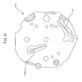
- an outer shape of the main plate 202 is formed substantially in a circular shape centering on the main plate center 202c. Further, the outer shape of the main plate 202 may be constituted by other shape of a quadrangular shape, a polygonal shape, an elliptical shape or the like.
- the main plate 202 may be formed by an engineering plastic of polycarbonate, polysulfone or the like, or may be formed by a metal of brass or the like.
- the rotation center of the center wheel & pinion 244 and the rotation center of the hour wheel 262 are arranged at the main plate center 202c.
- the center axis line of the center pipe 202b is arranged at the main plate center 202c.
- the main plate 202 includes rotation centers of rotating members of a rotation center 202RT of the rotor 236, a rotation center 202FW of the fifth wheel & pinion 238, a rotation center (not illustrated) of the fourth wheel & pinion 240, a rotation center (not illustrated) of the third wheel & pinion 242, a rotation center 202HW of the minute wheel 260, a rotation center of the setting wheel 278 (not illustrated) , a rotation center 202DW of the date indicator driving wheel 310, a rotation center 202DS of the date star wheel 312, a rotation center 202WT of the day indicator driving wheel 320, a rotation center 202SW of the small day wheel 322, a rotation center 202HG of the hour indicator 330, a rotation center 202BW of the second indicator 340, a rotation center 202SA of the third corrector setting transmission wheel 353, a rotation center 202SB of the date corrector setting wheel 355 and the like.
- the rotation center of the second corrector setting transmission wheel 352 is arranged at a position the same as that of the rotation center 202DS of the date star wheel 312. Further, the main plate 202 includes a fourth corrector setting transmission wheel guide long hole 202SL for movable guiding the lower shaft of the fourth corrector setting transmission wheel 354.
- the respective rotation centers are formed with guide shaft portions for guiding center holes of the rotating members, or formed with guide holes for guiding shaft portions of the rotating members in order to support the rotating members rotated centering on the rotation centers rotatably.
- the guide shaft portions, the guide holes constitute guiding portions for rotatably guiding the rotating members.
- the main plate 202 includes rotation centers for rotatably supporting respective rotating members used in other embodiment of the invention.
- the movement 201 includes a first train wheel rotation center for a train wheel used in fabricating the multifunction timepiece of a first type having an arrangement of a first type of a small hand.
- the first train wheel rotation center is arranged at a position between the main plate center 202c of the main plate 202 and a main plate outer shape portion of the main plate 202.
- the first train wheel rotation center is provided with a guide hole or a guide bearing for rotatably guiding a train wheel member rotated centering on the position.
- the movement 201 includes a second train wheel rotation center for a train wheel used in fabricating the multifunction timepiece of a second type having an arrangement of a second type of a small hand by using the movement 201.
- the second train wheel rotation center is arranged at a position between the main plate center 202c of the main plate 202 and the main plate outer shape portion of the main plate 202.
- the second train wheel rotation center is provided with a train wheel guide portion (guide hole, guide bearing, guide shaft, guide pin or the like) for rotatably guiding a train wheel member rotated centering on the position.
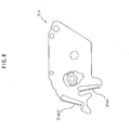
- the setting lever jumper 316 is a plate-like member formed by an elastic material of stainless steel, phosphor bronze or the like.
- the date jumper 316b for setting the position in the rotational direction of the date star wheel 312 is provided at the setting lever jumper 316. It is preferable to arrange a spring portion of the date jumper 316b at a region between "12 o'clock direction" and "3 o'clock direction” (that is, "12-3 o'clock region").
- a setting portion provided at a front end of a spring portion of the date jumper 316b at a region between "2 o'clock direction” and "3 o'clock direction” (that is, “2-3 o'clock region”).
- a day jumper 316c for setting a position in a rotational direction of the small day wheel 322 is provided at the setting lever jumper 316. It is preferable to arrange a spring portion of the day jumper 316c at a region between "6 o'clock direction” and “9 o'clock direction” (that is, "6-9 o'clock region”).
- the setting lever jumper 316 further includes a date jumper 316b2 and a day jumper 316c2 used in other embodiment of the invention.
- step motor Operation of step motor, train wheel, date feeding mechanism, day feeding mechanism or the like:
- the crystal oscillator contained in the crystal unit 222 is oscillated by, for example, 32,768 Hertz.
- an oscillating portion included in the integrated circuit 230 outputs the reference signal and the dividing portion divides the output signal of the oscillating portion.
- the driving portion outputs the motor drive signal for driving the step motor based on the output signal of the dividing portion.
- a stator 234 is magnetized to rotate the rotor 236.
- the rotor 236 is rotated by, for example, 180 degrees per 1 second. Based on rotation of the rotor 236, the fourth wheel & pinion 240 is rotated by way of rotation of the fifth wheel & pinion 238. Further, based on rotation of the rotor 236, the second indicator 340 is rotated by one rotation per 1 minute by way of rotation of the fifth wheel & pinion 238. The third wheel & pinion 242 is rotated based on rotation of the fourth wheel & pinion 240.
- the center wheel & pinion 244 is rotated by one rotation in 1 hour based on rotation of the third wheel & pinion 242.
- the minute wheel 260 is rotated based on rotation of the center wheel & pinion 244.
- the hour wheel 262 is rotated based on rotation of the minute wheel 260.
- the hour wheel 262 is rotated by one rotation per 12 hours.
- the date indicator driving wheel 310 is rotated.
- the date star wheel 312 is constituted to rotate by once per 1 day (1/31).
- the date star wheel 312 is constituted to rotate by one rotation per 31 days.
- the day indicator driving wheel 320 is rotated.
- the small day wheel 322 is rotated by once per 1 day (1/7). Therefore, the small day wheel 322 is rotated by one rotation per 7 days.
- the hour indicator 330 is rotated. The hour indicator 330 is rotated by one rotation per 24 hours.
- the fourth corrector setting transmission wheel 354 In the state of pulling the winding stem 210 to 1 stage, when the winding stem 210 is rotated in other direction, the fourth corrector setting transmission wheel 354 is moved in the direction of being remote from the date corrector setting wheel 355 by way of rotation of the first corrector setting transmission wheel 351, the second corrector setting transmission wheel 352, the third corrector setting transmission wheel 353. Under the state, the wheel portion of the fourth corrector setting transmission wheel 354 is not brought in mesh with the wheel portion of the date corrector setting wheel 355. Therefore, even when the winding stem 210 is rotated in other direction in the state of pulling the winding stem 210 to 1 stage, the date star wheel 312 cannot be rotated and date cannot be corrected.
- the setting wheel 278 is rotated by way of the rotation of the clutch wheel 274.
- the center pinion of the center wheel & pinion 244 and the hour wheel 262 are rotated by way of rotation of the minute wheel 260.
- the center pinion of the center wheel & pinion 244 can be slipped relative to the center wheel of the center wheel & pinion 244.
- time information with regard to "hour” of the 12 hour system can be indicated by the hour hand 262h attached to the hour wheel 262 the rotation center of which is the main plate center 202c
- time information with regard to "minute” can be indicated by the minute hand 244h attached to the center wheel & pinion 244 the rotation center of which is the main plate center 202
- time information with regard to "second” can be indicated by the small second hand 340h attached to the second indicator 340 the rotation center of which is arranged in "6 o'clock direction”
- time information with regard to "hour” of the 24 hour system can be indicated by the 24 hour hand 330h attached to the hour indicator 330 the rotation center of which is arranged in "12 o'clock direction”
- calendar information with regard to "date” can be indicated by the date hand 312h attached to the date star wheel 312 the rotation center of which is arranged in "3 o' clock direction”
- calendar information with regard to "day” can be indicated by the day hand 322h attached to the small
- a distance from the main plate center 202c to the rotation center of the date hand 312h, a distance from the main plate center 202c to the rotation center of the small second hand 340h, a distance from the main plate center 202c to the rotation center of the day hand 322h, and a distance from the main plate center 202c to the rotation center of the 24 hour hand 330h are equal.
- the distances between the centers can also be constituted not to be equal to each other.
- calendar information are provided at the dial 204.
- numerals of "6", “12", “18”, “24” are provided on a circumference at positions in correspondence with the 24 hour hand 330h of the dial 204.
- numerals of "10", “20”, “31” are provided on a circumference at positions in correspondence with the date hand 312h of the dial 204.
- time information with regard to "hour” of the 12 hour system can be indicated by the hour hand 262h
- time information with regard to "minute” can be indicated by the minute hand 244h
- time information with regard to "second” can be indicated by the small second hand 340h attached to the second indicator 340 the rotation center of which is arranged in "6 o' clock direction”
- the calendar information with regard to "date” can be indicated by the hour hand 312h attached to the date star wheel 312 the rotation center of which is arranged in "3 o'clock direction”
- the calendar information with regard to "day” can be indicated by the day hand 322h attached to the small day wheel 322 the rotation center of which is arranged in "9 o'clock direction”.
- the time information with regard to "hour” of the 12 hour system can be indicated by the hour hand 262h
- the time information with regard to "minute” can be indicated by the minute hand 244h
- the time information with regard to "second” can be indicated by the small second hand 340h attached to the second indicator 340 the rotation center of which is arranged in "6 o'clock direction”
- the time information with regard to "hour” of the 24 hour system can be indicated by the 24 hour hand 330h attached to the hour indicator 330 the rotation center of which is arranged in "12 o'clock direction”.
- the time information with regard to "hour” of the 12 hour system can be indicated by the hour hand 262h
- the time information with regard to "minute” can be indicated by the minute hand 244h
- the calendar information with regard to "date” can be indicated by the date hand 312h attached to the date star wheel 312 the rotation center of which is arranged in "3 o'clock direction”
- the calendar information with regard to "day” can be indicated by the day hand 322h attached to the small day wheel 322 the rotation center of which is arranged in "9 o'clock direction”.
- the time information with regard to "hour” of the 12 hour system can be indicated by the hour hand 262h
- the time information with regard to "minute” can be indicated by the minute hand 244h
- the time information with regard to "second” can be indicated by the small second hand 340h attached to the second indicator 340 the rotation center of which is arranged in "6 o'clock direction”.
- the sixth kind through the eighth kind of the embodiment of the invention illustrated in Fig. 10 will be described later.
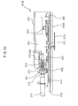
- a movement 20 includes a main plate 22 constituting a base plate of the movement 20.
- a top train wheel of a barrel complete, a center wheel & pinion, a third wheel & pinion, a fourth wheel & pinion and the like, an automatic winding mechanism of an oscillating weight, a pawl lever and the like, a switching mechanism of a barrel complete, a yoke and the like are respectively integrated to a top side of the movement 20.
- a structure on a back side of the movement can be constituted similar to the structure on the back side of the movement of the analog electronic timepiece shown in Fig. 1 and Fig. 2.
- a center wheel & pinion 24 is rotatably integrated to substantially a center of the main plate 22.
- the center wheel & pinion 24 is integrated between the main plate 22 and a second bridge 26.
- a cannon pinion 28 is integrated to a dial side of the main plate 22 to be able to slip relative to an outer peripheral portion of the center wheel & pinion 24 contiguous to a front end on a side proximate to a hand attaching portion thereof.
- the cannon pinion 28 is rotated integrally with the center wheel & pinion 24.
- a barrel complete 30 is rotatably integrated between the main plate 22 and a first bridge 32.
- a barrel wheel of the barrel complete 30 is brought in mesh with a center pinion of the center wheel & pinion 24.
- a third wheel & pinion 34 is rotatably integrated between the main plate 22 and the first bridge 32.
- a center wheel of the center wheel & pinion 24 is constituted to be brought in mesh with a third pinion.
- a fourth wheel & pinion 40 is rotatably integrated between the second bridge 26 and the first bridge 32.
- a third wheel of the third wheel & pinion 34 is constituted to be brought in mesh with a fourth pinion of the fourth wheel & pinion 40.
- An escape wheel & pinion 50 is rotatably integrated between the main plate 22 and the first bridge 32.
- a fourth wheel of the fourth wheel & pinion 40 is constituted to be brought in mesh with an escape pinion of the escape wheel & pinion 50.
- a number of train wheels is not limited to the above-described but one or more of transmission wheels may further be added.
- a pallet fork 60 is pivotably integrated between the main plate 22 and a pallet bridge 62.
- the pallet fork 60 includes twos claw jewels 63 and tips 64.
- An escape wheel of the escape wheel & pinion 50 is engaged with the claw jewel 63.
- a balance with hairspring 70 is rotatably integrated between the main plate 22 and a balance bridge 72.
- the balance with hairspring 70 includes a balance stem 71, a hairspring 74, an oscillating jewel 76, a hairspring ball 78, a balance ring 79.
- the tip 64 of the pallet fork 60 is constituted to be engaged with the oscillating jewel 76.
- a center portion of the balance ring 79 is fixed to the balance stem 71.
- An inner end portion of the hairspring 74 is fixed to the hairspring ball 78 fixed to the balance stem 71 .
- An outer peripheral portion 74g of the hairspring 74 is attached to a hairspring holder 72b.
- the hairspring holder 72b is attached to a hairspring holder bridge 72a.
- the hairspring holder bridge 72a is attached to the balance bridge 72.
- an hour wheel 80 is rotatably integrated to a side of the main plate 22 having a dial 82.
- a minute wheel & pinion 90 is rotatably integrated to the side of the main plate 22 having the dial 82.
- the minute wheel of the minute wheel & pinion 90 is brought in mesh with the cannon pinion 28.
- a minute pinion of the minute wheel & pinion 90 is constituted to be brought in mesh with the hour wheel 80.
- the date indicator driving wheel 310 (refer to Fig. 1) can be constituted to rotate by rotating the hour wheel 80.
- the day indicator driving wheel 320 (refer to Fig. 1) can be constituted to rotate by rotating the hour wheel 80.
- an oscillating weight 100 is rotatably integrated to the first bridge 32.
- the oscillating weight 100 is integrated to the first bridge 32 by way of a ball bearing (not illustrated) .
- a first transmission wheel (not illustrated) is rotatably integrated to be brought in mesh with a pinion (not illustrated) of the oscillating weight 100.
- a pawl lever (not illustrated) is rotatably integrated to an eccentric cam portion (not illustrated) of the first transmission wheel.
- a second transmission wheel (not illustrated) is rotatably integrated to a pawl lever to be engaged with a pawl portion (not illustrated) .
- a ratchet tooth (not illustrated) of the second transmission wheel is constituted to be engaged with the pawl portion of the pawl lever.
- the first transmission wheel (not illustrated) is rotated based on rotation of the oscillating weight 100, and based on operation of the pawl lever, the second transmission wheel is rotated only in a predetermined direction.
- a mainspring is constituted to wind.
- a yoke holder 140 by an elastically deformable material, for example, fabricate by stainless steel. It is preferable to fabricate a yoke 130 by an elastically deformable material, for example, fabricated by stainless steel.
- a spring portion 132 of the yoke 130 may be constituted by any shape of a linear shape, a bent shape, a U-like shape or the like.
- a mountain portion 142 of the yoke holder 140 is engaged with a positioning pin 122 of a setting lever 120 to determine a position of the setting lever 120 and sets a switch weight of the winding stem 110.
- the mountain portion 142 of the yoke holder 140 is constituted to be able to pull the winding stem 110 to 1 stage, and 2 stage.
- a spring force of the spring portion 132 of the yoke 130 By a spring force of the spring portion 132 of the yoke 130, a guide valley portion 138 of the yoke 130 is pressed to a side face of a front end portion of the setting lever 120.
- the barrel complete 30 is rotated.
- the center wheel & pinion 24 is rotated by rotation of the barrel complete 30.
- the third wheel & pinion 34 is rotated by rotation of the center wheel & pinion 24.
- the fourth wheel & pinion 40 is rotated by rotation of the third wheel & pinion 34.
- the cannon pinion 28 is simultaneously rotated by rotation of the center wheel & pinion 24.
- the minute wheel & pinion 90 is rotated by rotation of the cannon pinion 28.
- the hour wheel 80 is rotated by rotation of the minute wheel & pinion 90.
- Rotational speeds of the respective train wheels are controlled by operation of the balance with hairspring 70, the pallet fork 60 and the escape wheel & pinion 50.
- the fourth wheel & pinion 40 is rotated by one rotation in 1 minute.
- the cannon pinion 28 and the center wheel & pinion 24 are rotated by one rotation in 1 hour.
- the hour wheel 80 is rotated by one rotation in 12 hours.
- “Second” is indicated by a second hand 40h attached to the fourth wheel & pinion 40.
- “Minute” is indicated by a minute hand 28h attached to the cannon pinion 28.
- “Hour” is indicated by an hour hand 80h attached to the hour wheel 80. That is, the fourth wheel & pinion 40, the cannon pinion 28 and the center wheel & pinion 24, the hour wheel 80 constitute indicators for indicating time information. Time can be read by the hour hand 80h, the minute hand 28h, the second hand 40h, graduations of the dial 82 and the like.
- winding the mainspring by the automatic winding mechanism.
- the mechanical type timepiece is carried by the arm and the arm is swung forward/rearward.
- the mainspring can be wound by rotation of an automatic winding transmission wheel (not illustrated) or the like having ratchet teeth by operating the pawl lever as in operating an eccentric cam based on rotation of the oscillating weight 100.
- the winding stem 110 is pulled further to 2 stage.
- the setting lever 120 is further rotated.
- the yoke 130 is rotated in a direction reverse to the direction of the rotation by a spring force of the yoke to bring the A tooth 162a of the clutch wheel 162 in mesh with the hour wheel 90.
- time indication can be corrected by rotating the cannon pinion 28 and the hour wheel 80 by rotating the minute wheel 90.
- the hour wheel 80 is rotated based on rotation of the minute wheel 90.
- the hour wheel 80 is rotated by one rotation in 12 hours.
- the date indicator driving wheel 310 is rotated.
- the date star wheel 312 is rotated by once per 1 day (1/31) .
- the date star wheel 312 is constituted to rotate by one rotation in 31 days.
- the day indicator driving wheel 320 is rotated.
- the small day wheel 322 is rotated once per 1 day (1/7).
- the small day wheel 322 is rotated by one rotation in 7 days. Further, by rotation of the day indicator driving wheel 320, the hour indicator 330 is rotated. The hour indicator 330 is rotated by one rotation in 24 hours. According to a constitution of indicating "second" by the second hand 40h provided at the fourth wheel & pinion 40, the second indicator 340, the small second hand 340h can be omitted. Or, in a constitution of indicating "second" by the small second hand 340h, the second hand 40h can be omitted.
- the second embodiment of the multifunction timepiece of the invention is constituted by an analog electronic timepiece. Further in details, the second embodiment of the multifunction timepiece of the invention is constituted by an analog type timepiece (electric timepiece, electronic timepiece, mechanical type timepiece) including a small hand at at least one portion in "2 o'clock direction", "6 o'clock direction", "10 o'clock direction”.
- analog type timepiece electrical timepiece, electronic timepiece, mechanical type timepiece
- the second embodiment of the multifunction timepiece of the invention can be constituted such that time information with regard to "hour” of a 12 hour system is indicated by an hour hand a rotation center of which is a center of the main plate, time informationwithregardto"minute” is indicated by a minute hand a rotation center of which is the center of the main plate, time information with regard to "second” is indicated by a small second hand a rotation center of which is arranged in "6 o' clock direction", calendar information with regard to "date” is indicated by a date hand a rotation center of which is arranged in "2 o'clock direction”, calendar information with regard to "day” is indicated by a day hand a rotation center of which is arranged in "10 o' clock direction”.
- a movement can be constituted by a mechanical type timepiece.
- the second embodiment of the multifunction timepiece of the invention can also be constituted to constitute the movement by an analog electronic timepiece or a mechanical type timepiece and indicating time information with regard to "second" by a second hand a rotation center of which is a center of the main plate.
- a small second hand can be omitted.
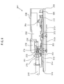
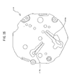
- a movement 201B includes a main plate 202.
- a power source portion, a circuit portion, a converter (step motor), a top train wheel, a switching mechanism and the like are arranged on a case back side (top side) of the main plate 202 .
- a back train wheel, a calendar train wheel, a date correcting mechanism and the like are arranged on a back side of the main plate 202.
- a dial 204B is arranged on a glass side of the main plate 202.
- a winding stem 210 is arranged to be rotatable on 3 o'clock side of the main plate 202.
- a point by which the second embodiment of the multifunction timepiece of the invention differs from the first embodiment of the multifunction timepiece of the invention resides in that the date indicating mechanism is arranged in "2 o'clock direction", that a date indicating mechanism is arranged in "10 o' clock direction", and that a 24 hour indicating mechanism is not provided. All of movement parts used in the second embodiment of the multifunction timepiece of the invention are the same as movement parts used in the first embodiment of the multifunction timepiece of the invention.
- the dial 204B used in the second embodiment of the multifunction timepiece of the invention differs from the dial 204 used in the first embodiment of the multifunction timepiece of the invention.
- a date indicator feeding mechanism is constituted to operate based on rotation of an hour wheel 262.
- the date indicating mechanism includes the date indicator driving wheel 310, the date star wheel 312.
- the date indicator driving wheel 310 is constituted to rotate by rotation of the hour wheel 262.
- the date indicator driving wheel 310 is rotatably supported by a second date indicator driving wheel pin provided at the main plate 202. It is preferable to arrange a rotation center of the date indicator driving wheel 310 at a region between "4 o'clock direction" and "5 o'clock direction” (that is, "4-5 o'clock region).
- a portion of the date corrector setting wheel holder 314 disposed on the lower side of the date star wheel 312 is narrowed in the circular shape to the back face of the main plate 202. It is preferable to set the hole provided at the center of the circular shape narrowed portion of the date corrector setting transmission wheel holder 314 to the date corrector setting wheel transmission wheel holder guide shaft portion provided at the surrounding of the date star wheel guide hole.
- the position in the rotational direction of the date star wheel 312 is set by the second date jumper 316b2 provided at the setting lever jumper 316.
- the setting portion provided at the front end of the spring portion of the second date jumper 316b2 at the region between "12 o' clock direction” and "1 o' clock direction” (that is, “12-1 o'clock region”).
- the rotation center of the date star wheel 312 is arranged in "2 o'clock direction”.
- the lower shaft portion of the date star wheel 312 is rotatably supported by the main plate 202.
- the date hand 312h is attached to the upper shaft portion of the date star wheel 312 (illustrated by two-dotted chain lines in Fig. 6).
- a day indicator feeding mechanism is constituted to operate based on rotation of the hour wheel 262.
- the day indicating mechanism includes the day indicator driving wheel 320, the small day wheel 322.
- the day indicator driving wheel 320 is constituted to rotate by rotation of the hour wheel 262.
- the day indicator driving wheel 320 is rotatably supported by a second day indicator driving wheel pin provided at the main plate 202. It is preferable to arrange the rotation center of the day indicator driving wheel 320 at a region between "8 o'clock direction" and "9 o'clock direction" (that is, "8-9 o'clock region").
- a position in the rotational direction of the small day wheel 322 is set by a second day jumper 316c2 provided at the setting lever jumper 316. It is preferable to arrange a correcting portion provided at a front end of the spring portion of the second day jumper 316c2 at a region between "9 o'clock direction" and "10 o'clock direction” (that is, “9-10 o'clock region”).
- the rotation center of the small day wheel 322 is arranged in "10 o'clock direction”.
- a lower shaft portion of the small day wheel 322 is rotatably supported by the main plate 202.
- the day hand 322h is attached to the upper shaft portion of the small day wheel 322.
- the date correcting mechanism is constituted by the first corrector setting transmission wheel 351, the second corrector setting transmission wheel 352, the third corrector setting transmission wheel 353, the fourth corrector setting transmission wheel 354 , and the date corrector setting wheel 355.
- the rotation center of the second corrector setting transmission wheel 352 is arranged in "3 o'clock direction".
- the rotation center of the second corrector setting transmission wheel 352 according to the second embodiment of the multifunction timepiece of the invention is arranged to be the same as the rotation center of the second corrector setting transmission wheel 352 according to the first embodiment of the multifunction timepiece of the invention.
- the third corrector setting transmission wheel 353 is rotatably supported by the main plate 202. It is preferable to arrange the rotation center of the third corrector setting transmission wheel 353 in "2 o'clock direction", or a region between "2 o'clock direction” and "3 o'clock direction” (that is, “2-3 o'clock region”).
- the rotation center of the third corrector setting transmission wheel 353 according to the second embodiment of the multifunction timepiece of the invention is arranged to be the same as the rotation center of the third corrector setting transmission wheel 353 according to the first embodiment of the multifunction timepiece of the invention.
- the lower shaft of the fourth corrector setting transmission wheel 354 is movably and rotatably supported by a second fourth corrector setting transmission wheel guide long hole provided at the main plate 202. It is preferable to arrange the second fourth corrector setting transmission wheel guide long hole for guiding the lower shaft of the fourth corrector setting transmission wheel 354 at a region between "1 o' clock direction" and "2 o' clock direction" (that is, 1-2 o' clock region”).
- the second fourth corrector setting transmission wheel guide long hole according to the second embodiment of the multifunction timepiece of the invention is arranged at a position more proximate to the outer shape portion of the main plate 202 than that of the fourth corrector setting transmission wheel guide long hole according to the first embodiment of the multifunction timepiece of the invention.
- the date corrector setting transmission wheel holder 314 is provided with the second correcting spring portion 314b2 for pressing the fourth corrector setting transmission wheel 354 to the main plate 202. It is preferable to arrange the rotation center of the date corrector setting wheel 355 at a region between "12 o'clock direction" and "1 o'clock direction” (that is, "12-1 o'clock region”).
- the main plate 202 further includes a rotation center 202DW2 of the date indicator driving wheel 310 according to the second embodiment, a rotation center 202DS2 of the date star wheel 312 according to the second embodiment, a rotation center 202WT2 of the date indicator driving wheel 320 according to the second embodiment, a rotation center 202SW2 of the small day wheel 322 according to the second embodiment, and a rotation center of a rotating member of a rotation center 202SB2 of the date corrector setting wheel 355 according to the second embodiment of the invention.
- the main plate 202 includes a second fourth corrector setting transmission wheel guide long hole 202SL2 for movably guiding the lower shaft of the fourth corrector setting transmission wheel 354 according to the second embodiment.
- the respective rotation centers are formed with guide shaft portions for guiding the center holes of the rotating members, or formed with guide holes for guiding shaft portions of the rotating members for rotatably supporting the rotating members rotated centering on the rotation centers. That is, the train wheel guide portion can be constituted by a guide hole, a guide bearing, a guide shaft, a guide pin or the like for rotatably guiding the rotating member.
- the main plate 202 includes the center pipe 202b arranged at the main plate center 202c, the lower bearing of the rotor 236, the lower bearing of the fifth wheel & pinion 238, the lower bearing of the fourth wheel & pinion 240, the lower bearing of the third wheel & pinion 242, the lower bearing of the minute wheel 260, the guide pin of the setting wheel 278, the guide pin of the date indicator driving wheel 310, the guide pin of the date star wheel 312, the guide pin of the day indicator driving wheel 320, the lower bearing of the small day wheel 322, the lower bearing of the hour indicator 330, the lower bearing of the second indicator 340, the guide pin of the third corrector setting transmission wheel 353, and the guide pin of the date corrector setting wheel 355.
- the bearing can be constituted by a hole jewel, a mortice frame, a through hole, a blind hole or the like.
- the guide pin can integrally be formed with the main plate 202, or a pin formed separately from the main plate 202 can be fixed to the main plate 202.
- the guide member of a pin or the like can also be used.
- a guide member of a hole jewel, a mortice frame, a through hole, a blind hole or the like can also be used.
- the movement 201 and the movement 201B include a first train wheel rotation center for a train wheel used for fabricating the first type of multifunction timepiece having an arrangement of the first type of small hand and a second train wheel rotation center for a train wheel used in fabricating the second type of multifunction timepiece having an arrangement of the second type of the small hand.
- the first train wheel rotation center and the second train wheel rotation center are provided with train wheel guide portions (guide holes, guide bearings, guide shafts, guide pins or the like) for rotatably guiding the train wheel members rotated centering on the positions.
- the first train wheel rotation center and the second train wheel rotation center are arranged at positions between the main plate center 202c of the main plate 202 and the main plate outer shape portion of the main plate 202.
- the main plate 202 can be used for the movement 201 and can also be used for the movement 201B.
- the date corrector setting transmission wheel holder 314 is provided with the second correcting spring portion 314b2 for pressing the fourth corrector setting transmission wheel 354 according to the second embodiment to the main plate 202. It is preferable to arrange the correcting spring portion 314b2 at a region between "1 o'clock direction" and "2 o'clock direction" (that is, "1-2 o' clock region”) .
- the date corrector setting transmission wheel holder 314 can be used for the movement 201 and can also be used for the movement 201B.
- the setting lever jumper 316 is provided with the second date jumper 316b2 for setting the position in the rotational direction of the date star wheel 312 according to the second embodiment. It is preferable to arrange the spring portion of the second date jumper 316b at a region between "1 o'clock direction" and "5 o'clock direction” (that is, "1-5 o'clock region").
- the setting lever jumper 316 is provided with the second day jumper 316c2 for setting the position in the rotational direction of the small day wheel 322 according to the second embodiment. It is preferable to arrange the spring portion of the second spring day jumper 316c2 at a region between "7 o' clock direction” and “10 o'clock direction” (that is, “7-10 o'clock region”).
- the setting portion provided at the front end of the spring portion of the second day jumper 316c2 at a region between "9 o' clock direction” and "10 o'clock direction” (that is, “9-10 o'clock region”).
- the setting lever jumper 316 can be used for the movement 201 and can also be used for the movement 201B.
- time information with regard to "hour” of the 12 hour system can be indicated by the hour hand 262h attached to the hour wheel 262 the rotation center of which is the main plate center 202c
- time information with regard to "minute” can be indicated by the minute hand 244h attached to the center wheel & pinion 244 the rotation center of which is the main plate center 202c
- time information with regard to "second” can be indicated by the small second hand 340h attached to the second indicator 340 the rotation center of which is arranged in "6 o'clock direction”
- calendar information with regard to "date” can be indicated by the date hand 312h attached to the date star wheel 312 the rotation center of which is arranged in "2 o'clock direction”
- calendar information with regard to "day” can be indicated by the day hand 322h provided at the small day wheel 322 the rotation center of which is arranged in "10 o'clock direction”.
- the dial 204B is provided with characters, numerals, abbreviated characters or the like for indicating the respective time information, calendar information.
- numerals of "10", “20”, “31” are provided along a circumference at positions in correspondence with the date hand 312h of the dial 204.
- numerals of "10", "20”, “30”, “40", “50”, "60” are provided along a circumference at positions in correspondence with the small second hand 340h of the dial 204.
- a movement is constituted by an analog electronic timepiece.
- the third embodiment of the multifunction timepiece of the invention is constituted by an analog type timepiece (electric timepiece, electronic timepiece, mechanical type timepiece) including a small hand at at least one portion in "3 o'clock direction", “6 o'clock direction”, “9 o'clock direction”, "12 o'clock direction”.
- time information with regard to "hour” of the 12 hour system is indicated by an hour hand a rotation center of which is a center of the main plate
- time information with regard to "minute” is indicated by a minute hand a rotation center of which is a center of the main plate
- time information with regard to "hour” of the 24 hour system is indicated by a 24 hour hand a rotation center of which is arranged in "12 o'clock direction”
- calendar information with regard to "date” is indicated by a date hand a rotation center of which is arranged in "3 o'clock direction”
- time information with regard to "second” is indicated by a small second hand a rotation center of which is arranged in "6 o' clock direction”
- calendar information with regard to "day” is indicated by a day hand a rotation center of which is arranged in "9 o'clock direction”.
- a movement can be constituted also by a mechanical type timepiece.
- a movement can be constituted by an analog electronic timepiece or a mechanical type timepiece, and time information with regard to "second" can be indicated by a second hand a rotation center of which is a center of the main plate.
- a small second hand can be omitted.
- a movement 401 includes a main plate 402.
- a power source portion, a circuit portion, a converter (step motor), a top train wheel, a switching mechanism and the like are arranged on a case back side (top side) of the main plate 402.
- a back train wheel, a calendar train wheel, a date correcting mechanism and the like are arranged on a back side of the main plate 402.
- the dial 204 is arranged on a glass side of the main plate 402.
- the winding stem 210 is arranged rotatably to a 3 o'clock side of the main plate 402.
- a point by which the third embodiment of the multifunction timepiece of the invention differs from the first embodiment of the multifunction timepiece of the invention resides in structures of the main plate, a date corrector setting transmission wheel holder, a setting lever jumper, a structure and an arrangement of a date correcting mechanism.
- Other movement parts used in the third embodiment of the multifunction timepiece of the invention can be constituted by those having dimensions and shapes the same as dimensions and shapes of the movement parts used in the first embodiment of the multifunction timepiece of the invention.
- the dial 204 used in the third embodiment of the multifunction timepiece of the invention can be constituted by that having a dimension and a shape the same as the dimension and the shape of the dial 204 used in the first embodiment of the multifunction timepiece of the invention.
- a date indicator feeding mechanism is constituted to operate based on rotation of the hour wheel 262.
- the date indicating mechanism includes the date indicator driving wheel 310 and the date star wheel 312.
- the date indicator driving wheel 310 is constituted to rotate by rotation of the hour wheel 262.
- the date indicator driving wheel 310 is rotatably supported by a date indicator driving wheel pin provided at the main plate 402. It is preferable to arrange the rotation center of the date indicator driving wheel 310 at a region between "5 o'clock direction" and "6 o' clock direction" (that is, "5-6 o'clock region).
- the position in the rotational direction of the date star wheel 312 is set by the date jumper 416b provided at the setting lever jumper 416. It is preferable to arrange the setting portion provided at the front end of the spring portion of the date jumper 416b at a region between "1 o'clock direction” and "2 o'clock direction” (that is, "1-2 o'clock region”).
- the rotation center of the date star wheel 312 is arranged in "3 o'clock direction”.
- the lower shaft portion of the date star wheel 312 is supported rotatably to the main plate 402.
- the date hand 312h is attached to the upper shaft portion of the date star wheel 312.
- a day indicating feeding mechanism is constituted to operate based on the rotation of the hour wheel 262.
- the day indicating mechanism includes the day indicator driving wheel 320 and the small day wheel 322.
- the day indicator driving wheel 320 is constituted to rotate by rotation of the hour wheel 262.
- the day indicator driving wheel 320 is rotatably supported by a day indicator driving wheel pin provided at the main plate 402. It is preferable to arrange the rotation center of the day indicator driving wheel 320 at a region between "10 o' clock direction" and "11 o' clock direction" (that is, "10-11 o' clock region").
- the position in the rotational direction of the small day wheel 322 is set by a day jumper 416c provided at the setting lever jumper 416. It is preferable to arrange the setting portion provided at the front end of the spring portion of the day jumper 416c at a region between "8 o'clock direction” and "9 o'clock direction” (that is, "8-9 o'clock region”).
- the rotation center of the small day wheel 322 is arranged in "9 o'clock direction”.
- a lower shaft portion of the small day wheel 322 is rotatably supported by the main plate 402.
- the day hand 322h is attached to the upper shaft portion of the small day wheel 322.
- the date correcting mechanism is constituted by a first corrector setting transmission wheel 451, a second corrector setting transmission wheel 452, a third corrector setting transmission wheel 453, a fourth corrector setting transmission wheel 454, and a date corrector setting wheel 455.
- a rotation center of the second corrector setting transmission wheel 452 is arranged in "3 o'clock direction".
- a dimension and a shape of the first corrector setting transmission wheel 451 according to the third embodiment of the multifunction timepiece of the invention can be constituted to be the same as a dimension and a shape of the first corrector setting transmission wheel 351 according to the first embodiment of the multifunction timepiece of the invention.
- a dimension and a shape of the second corrector setting transmission wheel 452 according to the third embodiment of the multifunction timepiece of the invention can be constituted to be the same the dimension and the shape of the second corrector setting transmission wheel 352 according to the first embodiment of the multifunction timepiece of the invention.
- a rotation center of the second corrector setting transmission wheel 452 according to the third embodiment of the multifunction timepiece of the invention can be arranged at a position the same as that of the rotation center of the second corrector setting transmission wheel 352 according to the first embodiment of the multifunction timepiece of the invention.
- a dimension and a shape of the fourth corrector setting transmission wheel 454 according to the third embodiment of the multifunction timepiece of the invention can be constituted to be the same the dimension and the shape of the fourth corrector setting transmission wheel 354 according to the first embodiment of the multifunction timepiece of the invention.
- a dimension and a shape of the date corrector setting wheel 455 according to the third embodiment of the multifunction timepiece of the invention can be constituted to be the same as the dimension and the shape of the date corrector setting wheel 355 according to the first embodiment of the multifunction timepiece of the invention.
- the third corrector setting transmission wheel 453 is rotatably supported by the main plate 402. It is preferable to arrange the rotation center of the third corrector setting transmission wheel 453 at a region between "3 o' clock direction” and "4 o'clock direction” (that is, “3-4 o'clock region”).
- a lower shaft of the fourth corrector setting transmission wheel 454 is movably and rotatably supported by a fourth correcting transmission wheel guide long hole provided at the main plate 402. It is preferable to arrange the fourth corrector setting transmission wheel guide long hole for guiding the lower shaft of the fourth corrector setting transmission wheel 454 at a region between "4 o' clock direction" and "5 o' clock direction” (that is, 4-5 o'clock region”).
- a date corrector setting transmission wheel holder 414 is provided with a correcting spring portion 414b for pressing the fourth corrector setting transmission wheel 454 to the main plate 402. It is preferable to arrange a rotation center of the date corrector setting wheel 355 in "4 o'clock direction", or a region between "3 o'clock direction” and “4 o'clock direction” (that is, “3-4 o'clock region”).
- the rotation center of the center wheel & pinion 244 and the rotation center of the hour wheel 262 are arranged at a main plate center 402c.
- the center axis line of the center pipe 202b is arranged at the main plate center 402c.
- the main plate 402 includes rotating centers of rotating members of a rotation center 402RT of the rotor 236, a rotation center of 402FW of the fifth wheel & pinion 238, a rotation center (not illustrated) of the fourth wheel & pinion 240, a rotation center (not illustrated) of the third wheel & pinion 242, a rotation center 402HW of the minute wheel 260, a rotation center (not illustrated) of the setting wheel 278, a rotation center 402DW of the date indicator driving wheel 310, a rotation center 402DS of the date star wheel 312, a rotation center 402WT of the day indicator driving wheel 320, a rotation center 402SW of the small day wheel 322, a rotation center 402HG of the hour indicator 330, a rotation center 402BW of the second indicator 340, a rotation center 402SA of the third corrector setting transmission wheel 353, a rotation center 402SB of the date corrector setting transmission wheel 355. It is preferable to arrange the rotation center of the second corrector setting transmission wheel 352
- the main plate 202 includes a fourth corrector setting transmission wheel guide long hole 402SL for movably guiding the lower shaft of the fourth corrector setting transmission wheel 354.
- the respective rotation centers are formed with guide shaft portions for guiding center holes of the rotating members or guide holes for guiding shaft portions of the rotating members in order to rotatably support the rotating members rotated centering on the rotation centers. That is, a train wheel guide portion for rotatably guiding the rotating member can be constituted by a guide hole, a guide bearing, a guide shaft, a guide pin or the like.
- the main plate 402 is further provided with rotation centers for rotatably supporting respective rotating members used in other embodiment of the invention.
- the movement 401 includes a first train wheel rotation center for a train wheel used in fabricating the first type of multifunction timepiece having an arrangement of a first type of a small hand.
- the first train wheel rotation center is arranged at a position between the main plate center 402c of the main plate 402 and a main plate outer shape portion of the main plate 402.
- the first train wheel rotation center is provided with a guide hole or a guide bearing for rotatably guiding a train wheel member rotated centering on the position.
- the movement 401 is provided with a second train wheel rotation center for a train wheel used for fabricating a second type of multifunction timepiece having an arrangement of a second type of a small hand by using the movement 401.
- the second train wheel rotation center is arranged at a position between the main plate center 402c of the main plate 402 and the main plate outer shape portion of the main plate 402.
- the second train wheel rotation center is provided with a guide portion (guide hole, guide bearing, guide shaft, guide pin or the like) for rotatably guiding a train wheel member rotated centering on the position.
- the date corrector setting transmission wheel holder 314 is arranged at "12-3 o'clock region" and "3-6 o'clock region”.
- a corrector spring portion 414b for pressing the fourth corrector setting transmission wheel 454 to the main plate 402 is provided at the date corrector setting transmission wheel holder 314. It is preferable to arrange the correcting spring portion 314b at a region between "4 o'clock direction" and "5 o'clock direction” (that is, "4-5 o'clock region”).
- the date corrector setting transmission wheel holder 414 is further provided with a correcting spring portion 414b2 used in other embodiment of the invention.
- the setting lever jumper 416 is provided with the date jumper 416b for setting a position in a rotational direction of the date star wheel 312. It is preferable to arrange a spring portion of the date jumper 416b at a region between "12 o'clock direction” and “2 o'clock direction” (that is, “12-2 o' clock region”). It is preferable to arrange a setting portion provided at a front end of the spring portion of the date jumper 416b at a region between "1 o'clock direction” and "2 o'clock direction” (that is, "1-2 o'clock region”).
- the setting lever jumper 416 is provided with the day jumper 416c for setting a position in a rotational direction of the small day wheel 322. It is preferable to arrange a spring portion of the day jumper 416c at a region between "7 o'clock direction” and “9 o'clock direction” (that is, “7-9 o'clock region”). It is preferable to arrange the setting portion provided at the front end of the spring portion of the day jumper 416c at a region between "8 o'clock direction" and “9 o'clock direction” (that is, “8-9 o'clock region”). Different from the first embodiment of the invention, in order to simplify fabricating steps, the further date jumper and the further day jumper used in other embodiment of the invention are not provided at the setting lever jumper 316.
- a hand position and a hand specification according to the third embodiment of the invention are similar to the hand position and the hand specification according to the first embodiment of the invention. That is, in reference to Fig. 10, the hand position and the hand specification according to the third embodiment of the invention can constitute the first kind through the fifth kind of the embodiment of the invention. Therefore, a detailed explanation with regard to the hand position and the hand specification according to the third embodiment of the invention is omitted to describe here again since the explanation with regard to the hand position and the hand specification according to the first embodiment of the invention may be referred to.
- the fourth embodiment of the multifunction timepiece of the invention is constituted by an analog electronic timepiece. Further in details, the fourth embodiment of the multifunction timepiece of the invention is constituted by an analog type timepiece (electric timepiece, electronic timepiece, mechanical type timepiece) including a small hand at at least one portion in "2 o'clock direction", "6 o'clock direction", "10 o'clock direction”.
- time information with regard to "hour” of the 12 hour system is indicated by an hour hand a rotation center of which is a center of the main plate
- time information with regard to "minute” is indicated by a minute hand a rotation center of which is the center of the main plate
- time information with regard to "second” is indicated by a small second hand a rotation center of which is arranged in "6 o'clock direction
- calendar information with regard to "date” is indicated by a date hand a rotation center of which is arranged in "2 o'clock direction”
- calendar information with regard to "day” is indicated by a day hand a rotation center of which is arranged in "10 o'clock direction”.
- a structure of a date indicating mechanism will be explained as follows.
- the date indicating mechanism includes the date indicator driving wheel 310 and the date star wheel 312.
- the date indicator driving wheel 310 is constituted to rotate by rotation of the hour wheel 262.
- the lower shaft portion of the date star wheel 312 is rotatably supported by the date star wheel guide hole provided at the main plate 402.
- the date indicator driving wheel 310 is rotatably supported by the second date indicator driving wheel pin provided at the main plate 402. It is preferable to arrange the rotation center of the date indicator driving wheel 310 at a region between "4 o'clock direction" and "5 o'clock direction” (that is, "4-5 o'clock region).
- the position in the rotational direction of the date star wheel 312 is set by the date jumper 418b provided at the setting lever jumper 418.
- the shape of the setting lever jumper 418 according to the fourth embodiment differs from the shape of the setting lever jumper 416 according to the third embodiment. It is preferable to arrange the setting portion provided at the front end of the spring portion of the date jumper 418b at a region between "12 o'clock direction" and "1 o'clock direction" (that is, "12-1 o'clock region”).
- the rotation center of the date star wheel 312 is arranged in "2 o'clock direction”.
- the lower shaft portion of the date star wheel 312 is supported rotatably to the main plate 402.
- the center hole of the second corrector setting transmission wheel 452 is rotatably supported by the second corrector setting transmission wheel guide shaft portion provided at the main plate 402.
- the inner side of the second corrector setting transmission wheel guide shaft portion is provided with the date star wheel guide hole for the date star wheel 312 used in the third embodiment of the multifunction timepiece of the invention.
- the center axis line of the date star wheel guide hole and the center axis line of the second corrector setting transmission wheel guide shaft portion can be constituted to coincide with each other.
- the third corrector setting transmission wheel 353 is rotatably supported by the ring-like third corrector setting transmission wheel guide shaft portion provided at the main plate 202.
- the inner side of the third corrector setting transmission wheel guide shaft portion is provided with the date corrector setting transmission wheel holder guide shaft portion.
- the inner side of the date corrector setting transmission wheel holder guide shaft portion is provided with the date star wheel guide hole of the date star wheel 312 used in the fourth embodiment of the multifunction timepiece of the invention.
- a portion of the date corrector setting transmission wheel holder 414 disposed on the lower side of the date star wheel 312 is narrowed in the circular shape to the back face of the main plate 402. It is preferable to fit the hole provided at the center of the circular shape narrowed portion of the date corrector setting transmission wheel holder 414 to the date corrector setting transmission wheel holder guide shaft portion provided at the surrounding of the date star wheel guide hole.
- the day indicator feeding mechanism is constituted to operate based on rotation of the hour wheel 262.
- the day indicating mechanism includes the day indicator driving wheel 320, and the small day wheel 322 .
- the day indicator driving wheel 320 is constituted to rotate by rotation of the hour wheel 262.
- the day indicator driving wheel 320 is rotatably supported by the second day indicator driving wheel pin provided at the main plate 402 . It is preferable to arrange the rotation center of the day indicator driving wheel 320 at a region between "8 o'clock direction" and "9 o'clock direction" (that is, "8-9 o'clock region").
- the position in the rotational direction of the small day wheel 322 is set by a day jumper 418c provided at the setting lever jumper 418. It is preferable to arrange the setting portion provided at the front end of the spring portion of the day jumper 418c at a region between "9 o'clock direction" and "10 o'clock direction" (that is, "9-10 o'clock region") .
- the rotation center of the small day wheel 322 is arranged in "10 o'clock direction”.
- a lower shaft portion of the small day wheel 322 is rotatably supported by the main plate 402.
- the day hand 322h is attached to the upper shaft portion of the small day wheel 322.
- a back side of the movement 401B is provided with a date correcting mechanism for correcting indication of date by the date star wheel 312.
- the date correcting mechanism is constituted by the first corrector setting transmission wheel 451, the second corrector setting transmission wheel 452, the third corrector setting transmission wheel 453, the fourth corrector setting transmission wheel 454, and the date corrector setting wheel 455.
- a rotation center of the second corrector setting transmission wheel 452 is arranged in "3 o'clock direction".
- the rotation center of the second corrector setting transmission wheel 452 according to the fourth embodiment of the multifunction timepiece of the invention can be arranged at a position the same as that of the rotation center of the second corrector setting transmission wheel 352 according to the first embodiment of the multifunction timepiece of the invention.
- the third corrector setting transmission wheel 453 is rotatably supported by the main plate 202. It is preferable to arrange the rotation center of the third corrector setting transmission wheel 453 in "2 o'clock direction", or a region between "2 o'clock direction” and “3 o' clock direction” (that is, “2-3 o'clock region”). It is preferable to arrange the rotation center of the third corrector setting transmission wheel 453 at a position the same as that of the rotation center of the date star wheel 312.
- the center hole of the third correcting setting transmission wheel 453 is rotatably arranged relative to the outer peripheral portion of the third corrector setting transmission wheel guide shaft portion provided at the main plate 402.
- the lower shaft of the fourth corrector setting transmission wheel 454 is movably and rotatably supported by the second fourth correcting transmission wheel guide long hole provided at the main plate 402. It is preferable to arrange the second fourth corrector setting transmission wheel guide long hole for guiding the lower shaft of the fourth corrector setting transmission wheel 454 at a region between "1 o'clock direction" and "2 o'clock direction” (that is, 1-2 o'clock region”).
- a second correcting spring portion 414b2 for pressing the fourth corrector setting transmission 454 to the main plate 402 is provided at the date corrector setting transmission wheel holder 414. It is preferable to arrange the rotation center of the date corrector setting wheel 455 at a region between "12 o'clock direction" and “1 o'clock direction” (that is, "12-1 o'clock region”).
- the main plate 402 further includes rotation centers of rotating members of a rotation center 402DW2 of the date indicator driving wheel 310 according to the fourth embodiment, a rotation center 402DS2 of the date star wheel 312 according to the fourth embodiment, a rotation center 402WT2of the day indicator driving wheel 320 according to the second embodiment, a rotation center 402SW2 of the small day wheel 322 according to the second embodiment, and a rotation center 402SB2 of the date corrector setting wheel 455 according to the second embodiment. It is preferable to arrange the rotation center of the third corrector setting transmission wheel 453 at a position the same as that of the rotation center 402DS2 of the date star wheel 312.
- the main plate 402 includes a second fourth corrector setting transmission wheel guide long hole 402SL2 for movably guiding the lower shaft of the fourth corrector setting transmission wheel 454 according to the fourth embodiment.
- the respective rotation centers are formed with guide shaft portions for guiding center holes of the rotating members, or guide holes for guiding shaft portions of the rotating members in order to rotatably support the rotating members rotated centering on the rotation centers. That is, a train wheel guide portion can be constituted by a guide hole, a guide bearing, a guide shaft, a guide pin or the like for rotatably guiding the rotating member.
- the movement 401 includes a first train wheel rotation center for a train wheel used in fabricating the first type of multifunction timepiece having an arrangement of a first type of a small hand, and a second train wheel rotation center for a train wheel used in fabricating a second type of multifunction timepiece having an arrangement of a second type small hand by using the movement 401B.
- the first train wheel rotation center and the second train wheel rotation center are provided with train wheel guide portions (guide holes, guide bearings, guide shafts, guide pins or the like) for rotatably guiding train wheel members rotated centering on the positions.
- the first train wheel rotation center and the second train wheel rotation center are arranged at positions between the main plate center 402c of the main plate 402 and the main plate outer shape portion of the main plate 402.
- the main plate 402 can be used for the movement 401 and can also be used in the movement 401B.
- a portion of the date corrector setting transmission wheel holder 414 disposed on the lower side of the date star wheel 312 is narrowed in the circular shape to the back face of the main plate 402 and the hole provided at the center of the circular shape narrowed portion is fitted to the date corrector setting transmission wheel holder guide shaft portion provided at the surrounding of the date star wheel guide hole.
- the date corrector setting transmission wheel holder 414 can be used for the movement 401 and can also be used for the movement 401B.
- the setting lever jumper 418 used in the fourth embodiment of the multifunction timepiece of the invention differs from the setting lever jumper 316 used in the third embodiment in shapes of the date jumper and the day jumper.
- a date jumper 418b for setting the position in the rotational direction of the date star wheel 312 according to the fourth embodiment is provided at the setting lever jumper 418. It is preferable to arrange a spring portion of the date jumper 418b at a region between "11 o'clock direction" and "1 o'clock direction" (that is, "11-1 o'clock region").
- a setting portion provided at a front end of the spring portion of the date jumper 418b at a region between "12 o' clock direction” and "1 o' clock direction” (that is, "12-1 o'clock region”).
- a day jumper 418c for setting a position in the rotational direction of the small day wheel 322 according to the fourth embodiment is provided at the setting lever jumper 418. It is preferable to arrange a spring portion of the day jumper 418c at a region between "7 o'clock direction” and “10 o'clock direction” (that is, “7-10 o'clock region”). It is preferable to arrange the setting portion provided at the front end of the spring portion of the day jumper 418c at a region between "9 o' clock direction" and "10 o' clock direction” (that is, "9-10 o'clock region”).
- a hand position and a hand specification according to the fourth embodiment of the invention are similar to the hand position and the hand specification according to the second embodiment of the invention. That is, in reference to Fig. 10, the hand position and the hand specification according to the fourth embodiment of the invention can constitute the sixth kind of the embodiment of the invention. Therefore, a detailed explanation with regard to the hand position and the hand specification according to the fourth embodiment of the invention will be omitted to describe here again since the explanation with regard to the hand position and the hand specification according to the second embodiment of the invention may be referred to.
- the point by which the fifth embodiment of the multifunction timepiece of the invention differs from the first embodiment of the multifunction timepiece of the invention resides in the day indicating mechanism. That is, a characteristic of the fifth embodiment of the multifunction timepiece of the invention resides in including a day hand of so-to-speak "retrograde type" capable of operating the hand in a fan shape.
- a movement is constituted by an analog electronic timepiece.
- the fifth embodiment of the multifunction timepiece of the invention is constituted by an analog type timepiece (electric timepiece, electronic timepiece, mechanical timepiece) including a small hand capable of being operated to rotate at at least one portion in "3 o' clock direction", “6 o' clock direction”, "12 o' clock direction”, and a small hand capable of being operated in a fan shape in "9 o'clock direction".
- time information with regard to "hour” of a 12 hour system is indicated by a time hand a rotation center of which is a center of a main plate
- time information with regard to "minute” is indicated by a minute hand a rotation center of which is the center of the main plate
- time information with regard to "hour” of a 24 hour system is indicated by a 24 hour hand a rotation center of which is arranged in "12 o'clock direction”
- calendar information with regard to "date” is indicated by a date hand a rotation center of which is arranged in "3 o'clock direction”
- time information with regard to "second” is indicated by a small second hand a rotation center of which is arranged in "6 o'clock direction”
- calendar information with regard to "day” is indicated by a so-to-speak "retrograde type" by a day hand a rotation center of which is arranged in "9 o'clock direction” and which can be operated in
- a day indicator feeding mechanism is constituted to operate based on rotation of the hour wheel 262.
- a day indicating mechanism includes a day indicator driving wheel 320, a day transmission wheel 462, a small day wheel 464, a hammer 466, a day jumper 468, and a day return spring 472.
- the day driving wheel 320 is constituted to rotate by rotation of the hour wheel 262.
- the day indicator driving wheel 320 is rotatably supported by a day indicator driving wheel pin 320p provided at the main plate 202. It is preferable to arrange a rotation center of the day indicator driving wheel 320 at a region between "10 o' clock direction" and "11 o' clock direction" (that is, "10-11 o'clock region").
- the day indicator driving wheel 320 includes a day indicator driving tooth 320b and a day indicator driving finger 320f.
- a date indicator driving pinion 262c of the hour wheel 262 is constituted to be brought in mesh with the day indicator driving tooth 320b of the day indicator driving wheel 320.
- the day transmission wheel 462 is rotatably supported by a day transmission wheel pin 462p provided at the main plate 202.
- the day transmission wheel 462 includes a day transmission wheel portion 462b, and a transmission cam portion 462c.
- the transmission cam portion 462c includes a transmission cam outer shape portion formed such that a distance from a center axis line of the day transmission wheel 462 (that is, cam radius) is gradually increased.
- the radius of the cam outer shape portion is formed to smoothly increase along a circumferential direction of a transmission cam outer periphery portion from a minimum value RMIN thereof to a maximum value RMAX thereof. Further, a stepped difference portion at which the radius of the transmission cam outer periphery portion is rapidly changed is arranged between the portion at which the radius of the transmission cam outer periphery portion is constituted by the maximum value RMAX and a portion at which the radius is constituted by the minimum value RMIN.
- the transmission cam outer periphery portion is provided with a contour shape which is widened uniformly in a spiral shape from the minimum radius portion the most proximate to the rotation center of the transmission cam outer shape portion to the maximum radius portion of the transmission cam outer shape portion and in which the portion constituted by the maximum value RMAX of the transmission cam outer periphery portion is connected to a portion constituted by the minimum value RMIN.
- the transmission cam outer periphery portion is constituted by a shape proximate to a cam face of a so-to-speak "rocking cam".
- the day transmission wheel portion 462b is arranged on a side of being proximate to a dial 454 than the transmission cam portion 462c.
- the day transmission wheel portion 462b of the day transmission wheel 462 includes 7 pieces of teeth.
- the small day wheel 464 includes a lower shaft portion 464a, a day wheel portion 464b, a return cam portion 464c, an upper shaft portion 464d, and a hand attaching portion 464g.
- the return cam portion 464c includes a return cam outer shape portion formed such that a distance from a center axis line of the small day wheel 464 (that is, cam radius) is gradually increased.
- the return cam outer shape portion is formed to constitute a well-known heart cam curve.
- the lower shaft portion of the small day wheel 464 is rotatably supported by the main plate 202.
- the upper shaft portion 464d of the small day wheel 464 is rotatably supported by a small day wheel bridge 470.
- a day hand 464h is attached to the hand attaching portion 464g of the small day wheel 464.
- the day return spring 472 includes a base portion 472b fixed to the main plate 202, and a return spring portion 472c constituted to press the return cam portion 464c of the small day wheel 464.
- the day return spring 472 is a plate-like member formed by an elastic material of stainless steel, phosphor bronze or the like.
- a front end portion of the return spring portion 472c is constituted to be brought into contact with the cam outer shape portion of the return cam portion 464c.
- a direction of a force of pressing the cam outer shape portion of the return cam portion 464c by the front end portion of the return spring portion 472c is directed to a portion of being eccentric from the rotation center of the small day wheel 464.
- a rotational moment for rotating the small day wheel 464 is constituted to generate by a rotational torque determined by a value of multiplying a distance of eccentricity from the rotation center of the small day wheel 464 to the eccentric portion by the press force. It is preferable to arrange the return spring portion 472c of the day return spring 472 at a region between "8 o' clock direction" and "9 o' clock direction” (that is, "8-9 o'clock region").
- a position in a rotational direction of the day transmission wheel 462 is constituted to be set by the day jumper 468 provided rotatably to the main plate 202.
- a day jumper press spring portion 480c provided at a setting lever jumper 480 is constituted to press a setting portion provided at a front end of the day jumper 468 to the day transmission wheel portion 4 62b of the day transmission wheel 462 . It is preferable to arrange a position of the setting portion provided at the front end of the day jumper 468 at a region between "9 o'clock direction" and "10 o'clock direction” (that is, “9-10 o'clock region”). It is preferable to arrange a position of the day jumper press spring portion 480c at a region between "9 o' clock direction" and "11 o'clock direction” (that is, "9-11 o'clock region”).
- the hammer 466 is rotatably supported by a hammer pin 466p provided at the main plate 202. It is preferable to arrange a position of the hammer 466 at a region between "9 o'clock direction" and "10 o'clock direction” (that is, “9-10 o'clock region”).
- the hammer 466 includes a cam contact portion 466c constituted to be brought into contact with the transmission cam portion 462c, a first operating wheel portion 466f and a second operating wheel portion 466g constituted to be brought in mesh with the day wheel portion 464b.
- the second operating wheel portion 466g is provided to be able to be brought in mesh with the day wheel portion 464b of the small day wheel 464. Particularly, in reference to Fig.
- the small day wheel 464 is constituted to receive a force of always being rotated in the counterclockwise direction. Therefore, the hammer 466 is constituted to always receive a force of being rotated in the clockwise direction. Therefore, a front end portion of the cam contact portion 466c of the hammer 466 is constituted to receive a force of being always pressed to the transmission cam portion 462c of the day transmission wheel 462.
- a rotation center of the small day wheel 464 is arranged in "9 o'clock direction".
- the wheel portion 4 64b, and the return cam portion 464c of the small day wheel 464 are arranged between the main plate 202 and the small day wheel bridge 370.
- the dial 454 is provided with a day character, a numeral, an abbreviated character or the like for indicating day. Particularly, in reference to Fig. 44, information with regard to "day" constituting one of calendar information is constituted to be able to be indicated by a day hand 464h operated in the fan shape, a character, a numeral, an abbreviated character or the like of the dial 454.
- the main plate 202 further includes a rotation center 202WD of the day transmission wheel 462 according to the fifth embodiment, a rotation center 202WF of the hammer 466 according to the fifth embodiment, a rotation center 202WT2 of the day indicator driving wheel 320 according to the fifth embodiment, a rotation center 202WG of the small day wheel 464 according to the fifth embodiment.
- the rotation center of the day indicator driving wheel 320 according to the fifth embodiment can be arranged at a position the same as that of the rotation center 202WT2 of the day indicator driving wheel 320 according to the first embodiment.
- the respective rotation centers are formed with guide shaft portions for guiding center holes of the rotating members, or formed with guide holes for guiding shaft portions of the rotating members for rotatably supporting the rotating members rotated centering on the rotation centers.
- the train wheel guide portion can be constituted by a guide hole, a guide bearing, a guide shaft, a guide pin or the like for rotatably guiding the rotating member.
- the main plate 202 includes the center pipe 202b arranged at the main plate center 202c, the lower bearing of the rotor 236, the lower bearing of the fifth wheel & pinion 238, the lower bearing of the fourth wheel & pinion 240, the lower bearing of the third wheel & pinion 242, the lower bearing of the minute wheel & pinion 260, the guide pin of the setting wheel 278, the guide pin of the day indicator driving wheel 310, the guide pin of the date star wheel 321, the guide pin of the day indicator driving wheel 320, the lower bearing of the small day wheel 322, the lower bearing of the day indicator 330, the lower bearing of the second indicator 340, the guide pin of the third corrector setting transmission wheel 353, the guide pin of the date corrector setting wheel 355, the guide pin of the day transmission wheel 462, a guide pin of the hammer 466, and a guide pin of the small day wheel 464.
- the bearing can be constituted by a hole jewel, a mortice frame, a through hole, a blind hole or the like.
- the guide pin can be formed integrally with the main plate 202, or a pin formed separately from the main plate 202 can be fixed to the main plate 202.
- the guide member of a pin or the like can also be used.
- a guide member of a hole jewel, a mortice frame, a through hole, a blind hole or the like can also be used.
- the movement 201, the movement 201B, and the movement 451 include a first train wheel rotation center for a train wheel used in fabricating a first type of multifunction timepiece having an arrangement of a first type of small hand, a second train wheel rotation center for a train wheel used in fabricating a second type of multifunction timepiece having an arrangement of a second type of small hand, and a third train wheel rotation center for a train wheel used in fabricating a third type of multifunction timepiece having an arrangement of a third type of small hand.
- the first train wheel rotation center, the second train wheel rotation center, the third train wheel rotation center are provided with train wheel guide portions (guide holes, guide bearings, guide shafts, guide pins or the like) for rotatably guiding train wheel members rotated centering on the positions.
- the first train wheel rotation center, the second train wheel rotation center, the third train wheel rotation center are arranged at positions between the main plate center 202c of the main plate 202 and the main plate outer shape portion of the main plate 202.
- the main plate 202 can be used for the movement 201, and can be used for the movement 201B, and can be used for the movement 451.
- the setting lever jumper 480 used in the fifth embodiment of the multifunction timepiece of the invention differs from the setting lever jumper 316 used in the first embodiment in shapes of the date jumper, and the day jumper. In reference to Fig.
- the setting lever jumper 480 includes a first day jumper 480a for setting a position in a rotational direction of the date star wheel 312 according to the first embodiment, a second date jumper 480b for setting a position in a rotational direction of the date star wheel 312 according to the second embodiment, and a day jumper press spring portion 480c for pressing a setting portion provided at a front end of the day jumper 316c to the day transmission wheel portion 462b of the day transmission wheel 462 according to the fifth embodiment.
- a spring portion of the first date jumper 481a at a region between "2 o'clock direction” and “6 o'clock direction” (that is, “2-6 o'clock region”). It is preferable to arrange a setting portion provided at a front end of a spring portion of the first date jumper 480a at a region between "1 o'clock direction” and “3 o'clock direction” (that is, “1-3 o'clock region”) . It is preferable to arrange a spring portion of the second date jumper 480b at a region between "11 o'clock direction” and “1 o'clock direction” (that is, “11-1 o'clock region”).
- a setting portion provided at a front end of a spring portion of the second date jumper 480b at a region between "12 o'clock direction” and “1 o'clock direction” (that is, “12-1 o'clock region”). It is preferable to arrange a position of the day jumper press spring portion 480c at a region between "9 o' clock direction” and "11 o'clock direction” (that is, “9-11 o'clock region”).
- a setting lever jumper 482 includes a date jumper 482a for setting a position in a rotational direction of the date star wheel 312 according to the first embodiment, and a day jumper press spring portion 482c for pressing the setting portion provided at a front end of the day jumper 316c to the day transmission wheel portion 462b of the day transmission wheel 462 according to the fifth embodiment.
- the setting lever jumper 482 constituted as described above cannot be used in the second embodiment. It is preferable to arrange a spring portion of the date jumper 482a at a region between "12 o' clock direction" and "2 o'clock direction" (that is, "12-2 o' clock region”) . It is preferable to arrange a setting portion provided at a front end of the spring portion of the date jumper 482a at a region between "1 o'clock direction" and "2 o'clock direction” (that is, "1-2 o'clock region”).
- the front end portion of the return spring portion 472c is brought into contact with the portion proximate to the minimum radius of the cam outer shape portion of the return cam portion 464c.
- the position in the rotational direction of the day transmission wheel 462 is set by the day jumper 316c rotatably provided to the main plate 202.
- the day jumper press spring portion 480c provided at the setting lever jumper 316 presses the setting portion provided at the front end of the day jumper 316c to the day transmission wheel portion 462b of the day transmission wheel 462.
- the cam contact portion 466c of the hammer 466 is brought into contact with the transmission cam portion 462c of the day transmission wheel 462.
- the first operating wheel portion 466f of the hammer 466 is brought in mesh with the day wheel portion 464b of the small day wheel 464 .
- the return spring portion 472c of the day return spring 472 brings the return cam portion 464c of the small day wheel 464 into contact with the portion proximate to the minimum radius of the cam outer shape portion of the small day wheel 464.
- the small day wheel 464 always receives the force of being rotated in the counterclockwise direction.
- the hammer 466 always receives the force of being rotated in the clockwise direction.
- the front end portion of the cam contact portion 466c of the hammer 466 always receives the force of being pressed to the transmission cam portion 462c of the day transmission wheel 462.
- the front end portion of the return spring portion 472c is rotated by an amount of 1 day to be brought into contact with the position at which the radius is enlarged from the minimum radius of the cam outer shape portion of the return cam portion 464c.
- the position in the rotational direction of the day transmission wheel 462 is set by the day jumper 316c provided rotatably to the main plate 202.
- the first operating wheel portion 466f of the hammer 466 rotates the small day wheel 464 by an amount of 1 day to bring about a state of instructing "Mon" expressing "Monday".
- the return spring portion 472c of the day return spring 472 is brought into contact with the position at which the radius is enlarged by rotating the return cam portion 464c of the small day wheel 464 by an amount of 1 day from the minimum radius of the cam outer shape portion of the small day wheel 464.
- the small day wheel 464 always receives a force of being rotated in the counterclockwise direction.
- the hammer 466 always receives a force of being rotated in the clockwise direction.
- the front end portion of the cam contact portion 466c of the hammer 466 always receives a force of being pressed to the transmission cam portion 462c of the day transmission wheel 462.
- a state of instructing "Tue” expressing “Tuesday” is brought about from the state of instructing "Mon” expressing “Monday”, successively, a state of instructing "Wed” expressing “Wednesday” is brought about, successively, a state of instructing "Thu” expressing “Thursday” is brought about, successively, a state of instructing "Fri” expressing "Friday” is brought about, successively, a state of instructing "Sat” expressing “Saturday” is brought about. Further, the state can be changed into a state of instructing "Sun” expressing "Sunday”.
- the return spring portion 472c of the day return spring 472 brings the return cam portion 464c of the small day wheel 464 into contact with the position the most proximate to the minimum radius of the cam outer shape portion of the small day wheel 464 from the position the most proximate to the maximum radius of the cam outer shape portion of the small day wheel 464.
- time information with regard to "hour” of the 12 hour system can be indicated by the hour hand 262h attached to the hour wheel 262 the rotation center of which is the main plate center 202c
- time information with regard to "minute” can be indicated by the minute hand 244h attached to the center wheel & pinion 244 the rotation center of which is the main plate center 202c
- time information with regard to "second” can be indicated by the small second hand 340h attached to the second indicator 340 the rotation center of which is arranged in "6 o'clock direction”
- calendar information with regard to "date” can be indicated by the date hand 312h attached to the date star wheel 312 the rotation center of which is arranged in "3 o'clock direction”
- calendar information with regard to "day” can be indicated by a so-to-speak "retrograde type" by the day hand 464h attached to the small day wheel 4 64 the rotation center of which is arranged in "9 o'clock direction”
- the day hand 464h can indicate calendar information with regard to "day” in a range of 90 degrees through 160 degrees. In view of allowance of design of constituent parts and design performance of day indication, it is preferable that the day hand 4 64h indicates calendar information with regard to "day” in a range of 100 degrees through 120 degrees.
- a distance from the main plate center 202c to the rotation center of the minute hand 312h, a distance from the main plate center 202c to the rotation center of the small second hand 340h, a distance from the main plate center 202c to the rotation center of the 24 hour hand 330h to be equal to each other.
- the distance between the centers can also be constituted not to be equal to each other. It is preferable to constitute such that the distance from the main plate center 202c to the rotation center of the day hand 464h be larger than the distance from the main plate center 202c to the rotation center of the date hand 312h.
- the distance from the main plate center 202c to the rotation center of the day hand 464h be larger than the distance from the main plate center 202c to the rotation center of the 24 hour hand 330h. It is preferable to constitute such that the distance from the main plate center 202c the rotation center of the day hand 464h to be larger than the distance from the main plate center 202c to the rotation center of the small second hand 340h.
- the dial 204 is provided with characters, numerals, abbreviated characters or the like for indicating respective time information, and calendar information.
- numerals of "10", “20”, “31” are provided along a circumference at positions in correspondence with the date hand 312h of the dial 454.
- numerals of "10", "20”, “30”, “40", “50”, "60” are provided along a circumference at positions in correspondence with the small second hand 340h of the dial 454.
- time information with regard to "hour” of the 12 hour system can be indicated by the hour hand 262h attached to the hour wheel 262 the rotation center of which is the main plate center 202c
- time information with regard to "minute” can be indicated by the minute hand 244h attached to the center wheel & pinion 244 the rotation center of which is the main plate center 202c
- time information with regard to "second” can be indicated by the small second hand 340h attached to the second indicator 340 the rotation center of which is arranged in "6 o' clock direction”
- time information with regard to "hour” of the 24 hour system can be indicated by the 24 hour hand 330h attached to the hour indicator 330 the rotation center of which is arranged in "12 o'clock direction”
- calendar information with regard to "date” can be indicated by the date hand 312h attached to the date star wheel 312 the rotation center of which is arranged in "3 o'clock direction”
- calendar information with regard to "day” can be
- the analog multifunction timepiece of the invention can form a plurality of movement layouts including small hands including a plurality of types of hand operating train wheels by only changing positions of integrating parts without changing dimensions and shapes of parts of the movements. Further, the analog multifunction timepiece of the invention can form a plurality of movement layouts having small hands with excellent production efficiency since much time period is not needed for switching part working operations and steps of fabricating parts are small.
Landscapes
- Physics & Mathematics (AREA)
- General Physics & Mathematics (AREA)
- Electromechanical Clocks (AREA)
Applications Claiming Priority (1)
| Application Number | Priority Date | Filing Date | Title |
|---|---|---|---|
| PCT/JP2004/018728 WO2006064557A1 (fr) | 2004-12-15 | 2004-12-15 | Appareil horaire multifonction comprenant une pluralite de types de trains de roues a deplacement d'aiguille |
Publications (3)
| Publication Number | Publication Date |
|---|---|
| EP1826636A1 true EP1826636A1 (fr) | 2007-08-29 |
| EP1826636A4 EP1826636A4 (fr) | 2008-04-09 |
| EP1826636B1 EP1826636B1 (fr) | 2011-01-26 |
Family
ID=36587622
Family Applications (1)
| Application Number | Title | Priority Date | Filing Date |
|---|---|---|---|
| EP04807087A Active EP1826636B1 (fr) | 2004-12-15 | 2004-12-15 | Appareil horaire multifonction comprenant une pluralite de types de rouages pour le deplacement d`aiguilles |
Country Status (6)
| Country | Link |
|---|---|
| US (1) | US7443768B2 (fr) |
| EP (1) | EP1826636B1 (fr) |
| JP (1) | JP4721188B2 (fr) |
| CN (1) | CN100594451C (fr) |
| HK (1) | HK1116551A1 (fr) |
| WO (1) | WO2006064557A1 (fr) |
Cited By (3)
| Publication number | Priority date | Publication date | Assignee | Title |
|---|---|---|---|---|
| EP2085833A1 (fr) | 2008-01-31 | 2009-08-05 | CT Time S.A. | Mouvement d'horlogerie modulaire |
| WO2013127686A1 (fr) * | 2012-02-29 | 2013-09-06 | Eta Sa Manufacture Horlogère Suisse | Ajustement d'aiguille sous cadran |
| RU2570817C2 (ru) * | 2010-10-18 | 2015-12-10 | Эта Са Мануфактюр Орложэр Сюис | Часы с модульным аналоговым отображением |
Families Citing this family (3)
| Publication number | Priority date | Publication date | Assignee | Title |
|---|---|---|---|---|
| JP5715453B2 (ja) * | 2011-03-13 | 2015-05-07 | セイコーインスツル株式会社 | レトログラード表示機構及びこれを備えた時計 |
| US8820788B2 (en) * | 2011-05-09 | 2014-09-02 | Tk Holdings Inc. | Occupant restraint system |
| US9740172B2 (en) * | 2015-01-30 | 2017-08-22 | Seiko Epson Corporation | Timepiece |
Family Cites Families (8)
| Publication number | Priority date | Publication date | Assignee | Title |
|---|---|---|---|---|
| GB2166570B (en) * | 1984-09-26 | 1987-11-18 | Citizen Watch Co Ltd | Electronic timepiece with a chronograph system |
| CH667771GA3 (fr) * | 1986-05-29 | 1988-11-15 | ||
| CH666591GA3 (en) * | 1986-09-03 | 1988-08-15 | Watch face display mechanism - includes spring biased pointer urged across scale by snail cam and rack mechanism during specific time interval | |
| US5289452A (en) * | 1988-06-17 | 1994-02-22 | Seiko Epson Corporation | Multifunction electronic analog timepiece |
| CN1025460C (zh) * | 1988-06-17 | 1994-07-13 | 精工爱普生株式会社 | 多功能电子表 |
| JP3140700B2 (ja) | 1996-12-26 | 2001-03-05 | セイコーインスツルメンツ株式会社 | 多機能時計 |
| JP2002333490A (ja) * | 2001-05-08 | 2002-11-22 | Seiko Instruments Inc | カレンダ機構付き時計及びその製造方法 |
| JP2004020421A (ja) * | 2002-06-18 | 2004-01-22 | Seiko Instruments Inc | 複数モータを備えたアナログクロノグラフ時計 |
-
2004
- 2004-12-15 JP JP2006548611A patent/JP4721188B2/ja active Active
- 2004-12-15 EP EP04807087A patent/EP1826636B1/fr active Active
- 2004-12-15 CN CN200480044606A patent/CN100594451C/zh active Active
- 2004-12-15 US US11/667,177 patent/US7443768B2/en active Active
- 2004-12-15 WO PCT/JP2004/018728 patent/WO2006064557A1/fr active Application Filing
-
2008
- 2008-05-19 HK HK08105515.7A patent/HK1116551A1/xx not_active IP Right Cessation
Non-Patent Citations (2)
| Title |
|---|
| No further relevant documents disclosed * |
| See also references of WO2006064557A1 * |
Cited By (12)
| Publication number | Priority date | Publication date | Assignee | Title |
|---|---|---|---|---|
| EP2085833A1 (fr) | 2008-01-31 | 2009-08-05 | CT Time S.A. | Mouvement d'horlogerie modulaire |
| WO2009095466A1 (fr) * | 2008-01-31 | 2009-08-06 | Ct Time S.A. | Mouvement d'horlogerie modulaire |
| WO2009095465A1 (fr) * | 2008-01-31 | 2009-08-06 | Ct Time S.A. | Mouvement d'horlogerie modulaire |
| JP2011511283A (ja) * | 2008-01-31 | 2011-04-07 | セーテー タイム エスアー | タイムピースのモジュール型ムーブメント |
| JP2011511284A (ja) * | 2008-01-31 | 2011-04-07 | セーテー タイム エスアー | 時計のモジュール型ムーブメント |
| US8238201B2 (en) | 2008-01-31 | 2012-08-07 | CT Time SA | Modular timepiece movement |
| US8331202B2 (en) | 2008-01-31 | 2012-12-11 | Ct Time S.A. | Modular horological movement |
| RU2476919C2 (ru) * | 2008-01-31 | 2013-02-27 | СиТи ТАЙМ С.А. | Модульный часовой механизм |
| RU2484515C2 (ru) * | 2008-01-31 | 2013-06-10 | СиТи ТАЙМ С.А. | Модульный механизм часов |
| RU2570817C2 (ru) * | 2010-10-18 | 2015-12-10 | Эта Са Мануфактюр Орложэр Сюис | Часы с модульным аналоговым отображением |
| WO2013127686A1 (fr) * | 2012-02-29 | 2013-09-06 | Eta Sa Manufacture Horlogère Suisse | Ajustement d'aiguille sous cadran |
| US9329573B2 (en) | 2012-02-29 | 2016-05-03 | Eta Sa Manufacture Horlogere Suisse | Below dial hand fitting |
Also Published As
| Publication number | Publication date |
|---|---|
| EP1826636A4 (fr) | 2008-04-09 |
| CN101080680A (zh) | 2007-11-28 |
| EP1826636B1 (fr) | 2011-01-26 |
| JP4721188B2 (ja) | 2011-07-13 |
| JPWO2006064557A1 (ja) | 2008-06-12 |
| US20080130419A1 (en) | 2008-06-05 |
| US7443768B2 (en) | 2008-10-28 |
| HK1116551A1 (en) | 2008-12-24 |
| CN100594451C (zh) | 2010-03-17 |
| WO2006064557A1 (fr) | 2006-06-22 |
Similar Documents
| Publication | Publication Date | Title |
|---|---|---|
| EP1672437A2 (fr) | Montre multifonction capable de constituer plusieurs dispositions de roues d'entraînement d'une aiguille rétrograde | |
| US7269101B2 (en) | Multifunction timepiece having fan shape moving hand mechanism including return spring and fan shape moving hand train wheel apparatus | |
| US8264912B2 (en) | Watch with calendar mechanism having two date indicators | |
| US7102962B2 (en) | Timepiece equipped with calendar mechanism including first and second date indicators | |
| US8059492B2 (en) | Calendar mechanism-attached timepiece having month indicator and date indicator | |
| US20110158052A1 (en) | Timepiece with calendar mechanism including first date indicator and second date indicator | |
| EP1672439A2 (fr) | Montre multifonction ayant une roue et un méchanisme d'entraînement d'une aiguille rétrograde | |
| EP1898277B1 (fr) | Appareil horaire multifonction capable de réaliser une pluralité d'agencements de mouvement | |
| US7532546B2 (en) | Timepiece with calendar mechanism having date indicators for indicating date | |
| JP4453645B2 (ja) | 時計の表示装置、ムーブメント、および時計 | |
| EP1826636B1 (fr) | Appareil horaire multifonction comprenant une pluralite de types de rouages pour le deplacement d`aiguilles | |
| US20070097794A1 (en) | Timepiece with a fan-shaped hand motion display mechanism | |
| JP4947119B2 (ja) | 時計 | |
| US8284632B2 (en) | Calendar mechanism equipped timepiece including two date indicators | |
| JP5467596B2 (ja) | カレンダ機構付き時計 | |
| CN217213441U (zh) | 用于钟表日期机芯的日历模块 | |
| US20060193208A1 (en) | Timepiece with small hand indicating mechanism | |
| JP4858418B2 (ja) | 時計 | |
| JP2006170765A (ja) | 日修正機構を備えた小針付き多機能時計 |
Legal Events
| Date | Code | Title | Description |
|---|---|---|---|
| PUAI | Public reference made under article 153(3) epc to a published international application that has entered the european phase |
Free format text: ORIGINAL CODE: 0009012 |
|
| 17P | Request for examination filed |
Effective date: 20070604 |
|
| AK | Designated contracting states |
Kind code of ref document: A1 Designated state(s): CH FR LI |
|
| DAX | Request for extension of the european patent (deleted) | ||
| RBV | Designated contracting states (corrected) |
Designated state(s): CH FR LI |
|
| A4 | Supplementary search report drawn up and despatched |
Effective date: 20080306 |
|
| RIC1 | Information provided on ipc code assigned before grant |
Ipc: G04B 19/24 20060101AFI20080229BHEP |
|
| 17Q | First examination report despatched |
Effective date: 20090824 |
|
| GRAP | Despatch of communication of intention to grant a patent |
Free format text: ORIGINAL CODE: EPIDOSNIGR1 |
|
| GRAS | Grant fee paid |
Free format text: ORIGINAL CODE: EPIDOSNIGR3 |
|
| GRAA | (expected) grant |
Free format text: ORIGINAL CODE: 0009210 |
|
| AK | Designated contracting states |
Kind code of ref document: B1 Designated state(s): CH FR LI |
|
| REG | Reference to a national code |
Ref country code: CH Ref legal event code: EP |
|
| REG | Reference to a national code |
Ref country code: CH Ref legal event code: NV Representative=s name: PATENTANWAELTE SCHAAD, BALASS, MENZL & PARTNER AG |
|
| PLBE | No opposition filed within time limit |
Free format text: ORIGINAL CODE: 0009261 |
|
| STAA | Information on the status of an ep patent application or granted ep patent |
Free format text: STATUS: NO OPPOSITION FILED WITHIN TIME LIMIT |
|
| 26N | No opposition filed |
Effective date: 20111027 |
|
| PGFP | Annual fee paid to national office [announced via postgrant information from national office to epo] |
Ref country code: FR Payment date: 20130107 Year of fee payment: 9 |
|
| REG | Reference to a national code |
Ref country code: FR Ref legal event code: ST Effective date: 20140829 |
|
| PG25 | Lapsed in a contracting state [announced via postgrant information from national office to epo] |
Ref country code: FR Free format text: LAPSE BECAUSE OF NON-PAYMENT OF DUE FEES Effective date: 20131231 |
|
| PGFP | Annual fee paid to national office [announced via postgrant information from national office to epo] |
Ref country code: CH Payment date: 20240102 Year of fee payment: 20 |