EP1826595B1 - Verfahren zur Herstellung eines polarisierenden optischen Elements - Google Patents
Verfahren zur Herstellung eines polarisierenden optischen Elements Download PDFInfo
- Publication number
- EP1826595B1 EP1826595B1 EP07290194.5A EP07290194A EP1826595B1 EP 1826595 B1 EP1826595 B1 EP 1826595B1 EP 07290194 A EP07290194 A EP 07290194A EP 1826595 B1 EP1826595 B1 EP 1826595B1
- Authority
- EP
- European Patent Office
- Prior art keywords
- layer
- optical element
- multilayer structure
- temporary support
- base optical
- Prior art date
- Legal status (The legal status is an assumption and is not a legal conclusion. Google has not performed a legal analysis and makes no representation as to the accuracy of the status listed.)
- Active
Links
Images


Classifications
-
- B—PERFORMING OPERATIONS; TRANSPORTING
- B29—WORKING OF PLASTICS; WORKING OF SUBSTANCES IN A PLASTIC STATE IN GENERAL
- B29C—SHAPING OR JOINING OF PLASTICS; SHAPING OF MATERIAL IN A PLASTIC STATE, NOT OTHERWISE PROVIDED FOR; AFTER-TREATMENT OF THE SHAPED PRODUCTS, e.g. REPAIRING
- B29C41/00—Shaping by coating a mould, core or other substrate, i.e. by depositing material and stripping-off the shaped article; Apparatus therefor
- B29C41/24—Shaping by coating a mould, core or other substrate, i.e. by depositing material and stripping-off the shaped article; Apparatus therefor for making articles of indefinite length
- B29C41/32—Making multilayered or multicoloured articles
-
- B—PERFORMING OPERATIONS; TRANSPORTING
- B29—WORKING OF PLASTICS; WORKING OF SUBSTANCES IN A PLASTIC STATE IN GENERAL
- B29C—SHAPING OR JOINING OF PLASTICS; SHAPING OF MATERIAL IN A PLASTIC STATE, NOT OTHERWISE PROVIDED FOR; AFTER-TREATMENT OF THE SHAPED PRODUCTS, e.g. REPAIRING
- B29C63/00—Lining or sheathing, i.e. applying preformed layers or sheathings of plastics; Apparatus therefor
- B29C63/02—Lining or sheathing, i.e. applying preformed layers or sheathings of plastics; Apparatus therefor using sheet or web-like material
-
- B—PERFORMING OPERATIONS; TRANSPORTING
- B29—WORKING OF PLASTICS; WORKING OF SUBSTANCES IN A PLASTIC STATE IN GENERAL
- B29D—PRODUCING PARTICULAR ARTICLES FROM PLASTICS OR FROM SUBSTANCES IN A PLASTIC STATE
- B29D11/00—Producing optical elements, e.g. lenses or prisms
- B29D11/0073—Optical laminates
-
- G—PHYSICS
- G02—OPTICS
- G02B—OPTICAL ELEMENTS, SYSTEMS OR APPARATUS
- G02B5/00—Optical elements other than lenses
- G02B5/30—Polarising elements
- G02B5/3025—Polarisers, i.e. arrangements capable of producing a definite output polarisation state from an unpolarised input state
- G02B5/3033—Polarisers, i.e. arrangements capable of producing a definite output polarisation state from an unpolarised input state in the form of a thin sheet or foil, e.g. Polaroid
- G02B5/3041—Polarisers, i.e. arrangements capable of producing a definite output polarisation state from an unpolarised input state in the form of a thin sheet or foil, e.g. Polaroid comprising multiple thin layers, e.g. multilayer stacks
- G02B5/305—Polarisers, i.e. arrangements capable of producing a definite output polarisation state from an unpolarised input state in the form of a thin sheet or foil, e.g. Polaroid comprising multiple thin layers, e.g. multilayer stacks including organic materials, e.g. polymeric layers
-
- B—PERFORMING OPERATIONS; TRANSPORTING
- B29—WORKING OF PLASTICS; WORKING OF SUBSTANCES IN A PLASTIC STATE IN GENERAL
- B29K—INDEXING SCHEME ASSOCIATED WITH SUBCLASSES B29B, B29C OR B29D, RELATING TO MOULDING MATERIALS OR TO MATERIALS FOR MOULDS, REINFORCEMENTS, FILLERS OR PREFORMED PARTS, e.g. INSERTS
- B29K2995/00—Properties of moulding materials, reinforcements, fillers, preformed parts or moulds
- B29K2995/0018—Properties of moulding materials, reinforcements, fillers, preformed parts or moulds having particular optical properties, e.g. fluorescent or phosphorescent
- B29K2995/0034—Polarising
-
- B—PERFORMING OPERATIONS; TRANSPORTING
- B29—WORKING OF PLASTICS; WORKING OF SUBSTANCES IN A PLASTIC STATE IN GENERAL
- B29L—INDEXING SCHEME ASSOCIATED WITH SUBCLASS B29C, RELATING TO PARTICULAR ARTICLES
- B29L2025/00—Frameless domes
-
- C—CHEMISTRY; METALLURGY
- C09—DYES; PAINTS; POLISHES; NATURAL RESINS; ADHESIVES; COMPOSITIONS NOT OTHERWISE PROVIDED FOR; APPLICATIONS OF MATERIALS NOT OTHERWISE PROVIDED FOR
- C09K—MATERIALS FOR MISCELLANEOUS APPLICATIONS, NOT PROVIDED FOR ELSEWHERE
- C09K2323/00—Functional layers of liquid crystal optical display excluding electroactive liquid crystal layer characterised by chemical composition
-
- C—CHEMISTRY; METALLURGY
- C09—DYES; PAINTS; POLISHES; NATURAL RESINS; ADHESIVES; COMPOSITIONS NOT OTHERWISE PROVIDED FOR; APPLICATIONS OF MATERIALS NOT OTHERWISE PROVIDED FOR
- C09K—MATERIALS FOR MISCELLANEOUS APPLICATIONS, NOT PROVIDED FOR ELSEWHERE
- C09K2323/00—Functional layers of liquid crystal optical display excluding electroactive liquid crystal layer characterised by chemical composition
- C09K2323/02—Alignment layer characterised by chemical composition
-
- Y—GENERAL TAGGING OF NEW TECHNOLOGICAL DEVELOPMENTS; GENERAL TAGGING OF CROSS-SECTIONAL TECHNOLOGIES SPANNING OVER SEVERAL SECTIONS OF THE IPC; TECHNICAL SUBJECTS COVERED BY FORMER USPC CROSS-REFERENCE ART COLLECTIONS [XRACs] AND DIGESTS
- Y10—TECHNICAL SUBJECTS COVERED BY FORMER USPC
- Y10T—TECHNICAL SUBJECTS COVERED BY FORMER US CLASSIFICATION
- Y10T428/00—Stock material or miscellaneous articles
- Y10T428/24—Structurally defined web or sheet [e.g., overall dimension, etc.]
- Y10T428/2419—Fold at edge
- Y10T428/24215—Acute or reverse fold of exterior component
- Y10T428/24231—At opposed marginal edges
- Y10T428/2424—Annular cover
- Y10T428/24248—One piece
Definitions
- the present invention relates to a method of producing a polarizing optical element, as well as an optical element obtained by this method. It also relates to a layered structure useful for producing such a polarizing optical element.
- polarizing optical elements and especially polarizing ophthalmic lenses
- Such elements can remove parasitic reflections from the field of view that come from flat or near-horizontal horizontal surfaces.
- This type of lens for example, is conventionally obtained in the ophthalmic industry using a polarizing film.
- the material most conventionally used to make polarizing films is PVA (Polyvinyl Alcohol).
- PVA film can be used alone or sandwiched between two protective films so as to form a less delicate composite film, for example between two Polycarbonate films.
- the heating of the polarizing film causes an alteration thereof.
- its color and its polarization efficiency are modified unintentionally and in a non-reproducible manner.
- the overmolding method does not make it possible to obtain an optical element that has an optimized reduced total thickness. This is particularly troublesome for high refractive index materials.
- An object of the present invention is therefore to provide a method for producing a polarizing optical element, which does not have the disadvantages mentioned above.
- the surface of the basic optical element is understood to mean the entire surface of this element or at least a part of its surface. area. According to the invention this surface of the basic optical element is pseudo-spherical.
- pseudo-spherical surface means a continuous concave or convex surface, that is to say a surface which is devoid of holes or steps.
- Such pseudo-spherical surfaces are in particular encountered when the optical element is an optical lens.
- at least one of the two faces of an optical lens is pseudo-spherical, so that the variation in thickness of the lens that results gives it an optical power.
- Afocal, unifocal, bifocal, trifocal and progressive ophthalmic lenses all have at least one pseudo-spherical face.
- a spherical surface corresponds to a particular case of pseudo-spherical surface, for which radii of curvature of the surface in two perpendicular directions are equal and uniform.
- the expression "pseudo-spherical surface” is understood to include the particular case of spherical surfaces.
- the layered structure which confers the polarizing function on the optical element, is first made on a temporary support, then separated from it and applied to the basic optical element.
- This sequence is made possible by the fact that the layered structure is sufficiently cohesive to be handled in isolation, that is to say without being supported by any support.
- the mechanical and physicochemical properties of the temporary support do not therefore intervene when the layer structure is applied to the basic optical element. This application can therefore be performed simply, taking into account only the mechanical behavior of the layered structure, without taking into account that of the temporary support.
- a first advantage of a method according to the invention lies in the possibility of producing a polarizing optical element whose thickness is optimized. Indeed, the layered structure is simply applied to a surface of the optical element, which does not significantly increase the thickness thereof.
- a second advantage of a method according to the invention lies in the fact that the layer structure can be produced on the temporary support in the form of a continuous film.
- a significant amount of the layered structure can thus be manufactured economically, by circulation of the temporary support through successive manufacturing sections.
- the structure, once disconnected from its support, can then be cut into segments which are applied individually on separate optical elements.
- the structure can be applied in its entirety at one time to several distinct elements, and then the elements can be separated from each other thereafter.
- a third advantage according to the invention is that the production of the polarizing film is totally detached from the production of the optical element. This is particularly interesting for the ophthalmic lens sector.
- a fourth advantage according to the invention is related to the fact that the application of the layer structure with polarizing property on the surface of an already constituted optical element makes it possible to perfectly match the profile of the receiving surface to the polarizing structure, with thus a very good control of the distance separating the surface of the layered structure from the surface of the optical element. This is particularly beneficial for guaranteeing particular dioptric properties for the polarizing optical element finally obtained, particularly in the case where the polarizing optical element is a progressive lens-type ophthalmic lens whose radius of curvature varies continuously on its surface.
- a fifth advantage of the method according to the invention stems from the fact that the temporary support can be recovered after the layered structure has been separated from it in step / b /.
- the recovered medium can be reused to make a new portion of layered structure.
- the linear polarization of the first ultraviolet radiation can be achieved by means of a polarizer which is interposed between a source of this first radiation and the first layer.
- the reaction under the effect of polarized radiation, photo-reactive groups that are carried by the photo-orientable polymer leads to the formation of an anisotropic polymer network, oriented according to the direction of the polarizer.
- the monomeric liquid crystals and the dichroic dyes may adopt, during step / a3 /, an orientation which is perpendicular to the direction of the polarizer, which has been imposed on the photo-orientable polymer of the first layer.
- This orientation of the dichroic dyes gives the system the polarization properties of visible light.
- the polymerization of the monomeric liquid crystals, in step / a4 /, then definitively stabilizes the configuration of the second layer.
- the polymerization of the second layer at the substep / a4 / is carried out using a dose of a second ultraviolet radiation which is adjusted so that the second layer has a glass transition temperature of less than or equal to Room temperature.
- the ambient temperature considered may vary by plus or minus 5 ° C. In general, she is close to 25 ° C.
- the amount of ultraviolet radiation that is used in the sub-step / a4 / allows to select a degree of polymerization of the second layer, and therefore to adjust its thermomechanical properties.
- Tg glass transition temperature
- Under-polymerization is understood to mean partial polymerization, with a degree of polymerization such that part of the polymerizing functions of the second layer has not yet reacted.
- Such polymerizing functions may be, in particular, acrylate or methacrylate functions.
- the dose of second ultraviolet radiation must be sufficiently high for the chemical gel point of the growing polymer to be reached, while remaining low enough for the glass transition temperature of the final material of the second layer to be adapted. relative to the operating temperature of the layered structure:
- the irradiation dose of the second layer is such that the material which is obtained after the pre-polymerization step has a glass transition temperature lower than the ambient temperature, this material has, at ambient temperature, mechanical properties which make it easy to manipulate and apply to the basic optical element.
- the second layer has a thickness of between 3 and 100 ⁇ m (micrometer), preferably between 5 and 50 ⁇ m, and more particularly between 5 and 10 ⁇ m. Under these conditions, the second layer can give the entire layer structure sufficient mechanical cohesion so that the structure can be manipulated in the form of a self-supported membrane, especially for step / c /.
- photo-orientable reactive polymers that may be used in the context of the invention, mention may be made, for example, of those formed from acrylic, methacrylic, polyimide and dendrimer polymers.
- Photo-orientable reactive polymers having photoreactive groups such as cinnamic acid and its derivatives, chalcones, coumarins, or methacrylate bridges are particularly conceivable.
- dichroic dyes that can be used in the context of the invention, mention may be made, for example, of azomethines, indigoids, thioindigoids, indanes, quinophthalones, perylenes, phthaloperines, triphenodioxazines, indoloquinoxalines, imidazotriazines, azo and polyazo dyes, benzoquinones, naphthoquinones, anthraquinones and (poly) anthraquinones, anthrapyrimidinones, iodines and iodates.
- azos and anthraquinones are used in the context of the invention.
- the layered structure may be applied at step / c / on the surface of the base optical element with a portion of an adhesive material disposed between the structure and that element.
- an adhesive material makes it possible to implement a method according to the invention for basic optical elements which have different chemical compositions, at the level of the surface on which the layered structure is applied.
- This adhesive material in the context of the invention may be applied on one side of the optical element and / or on the layer structure.
- the portion of adhesive material is disposed as an additional layer of the layered structure on one side of said structure.
- the layered structure contains all the components necessary to provide a polarizing function to any optical element. It is therefore sufficient to obtain the layered structure for producing a polarizing optical element from a single optical element.
- adhesive materials that may be used in the context of the invention, mention may be made, by way of indication and not limitation, of: epoxy adhesives, reactive polyurethane adhesives; thermosetting glues; adhesives based on polymerizable monomers such as cyanoacrylate adhesives; modified structural acrylic or acrylic adhesives; hot melts or hot melt adhesives; PVC plastisols (polyvinyl chloride); elastomeric adhesives, neoprene contact adhesive; vinyl and copolymer emulsion adhesives; pressure-sensitive adhesives (PSA); glues with water.
- epoxy adhesives reactive polyurethane adhesives
- thermosetting glues adhesives based on polymerizable monomers such as cyanoacrylate adhesives; modified structural acrylic or acrylic adhesives; hot melts or hot melt adhesives
- PVC plastisols polyvinyl chloride
- elastomeric adhesives neoprene contact adhesive
- vinyl and copolymer emulsion adhesives vinyl and copolymer e
- the use of a layer of pressure sensitive adhesive material, or PSA for "Pressure Sensitive Adhesive" in English is particularly advantageous because it allows to adhering the layer structure to the surface of the basic optical element in a simple and inexpensive manner while preserving the dioptric properties of the optical element.
- the possibility of depositing the PSA adhesive material in the form of a thin layer with parallel faces whose thickness may be between 0.5 and 200 microns makes it possible, when the basic optical element is an ophthalmic lens, to do not alter its nominal power whatever the relevant spatial area of the optical element. In this way, the bonding of the polarizing film is compatible with the precision that is necessary when the basic optical element is a progressive ophthalmic lens.
- a pressure-sensitive adhesive material does not require the use of irradiation, for example ultraviolet radiation, or intensive heating to obtain permanent bonding.
- irradiation for example ultraviolet radiation
- intensive heating to obtain permanent bonding.
- the polarizing layer structure is not impaired or degraded by such irradiation or heating.
- the dichroic dyes have an angular orientation that is determined by the first layer so as to produce a polarizing effect of the second layer for light transmitted through the structure. This orientation is definitively fixed by incorporating dichroic dyes into the matrix of crosslinkable monomeric liquid crystals.
- first and second layers are adapted to form a self-supported membrane.
- Such a layered structure can be arranged on a support, so that it can be separated from the latter. It can be a useful support during the manufacture of the structure. In addition, it can serve to condition the structure between the manufacture thereof and its subsequent use with an optical element.
- the layered structure may further comprise a layer of adhesive material.
- the portion of adhesive material is disposed in the form of an additional layer of the layered structure. It may further comprise at least one other functional layer, intended to provide an additional function to the optical element, at the same time as the polarization function. .
- the invention finally proposes a polarizing optical element which comprises a basic optical element and a layered structure as described above.
- This layered structure is fixed on a pseudo-spherical surface of the base optical element by a layer of adhesive material disposed between the base member and the layered structure. It gives the optical element a polarizing function for a light transmitted through this element.
- a layered structure 30 is carried by a support 31.
- the support 31 is selected from materials having a surface energy which is between 25 mN / m (milliNewton per meter) and 40 mN / m.
- the support 31 is made of polyethylene or polypropylene, which materials have respective surface energies of about 35 mN / m and 30 mN / m.
- the material of the support 31 has a relatively low surface energy, so that the layered structure 30 can be easily separated from the support 31, for example by peeling.
- an intermediate layer 32 is made between the support 31 and the structure 30, to facilitate a separation between the structure 30 and the support 31.
- Such an intermediate layer 32 is called a peel layer and may comprise, in particular, a tensio compound. silicone-based active ingredient.
- the figure 1b represents the layered structure 30, after it has been separated from the support 31.
- the support 31 is called temporary support. It is used to make the layered structure 30, and is removed before the structure 30 is applied to an optical element.
- the layered structure 30 comprises five elementary layers, referenced 33 to 37.
- the layer 33 which is formed first on the support 31 or over the peel layer 32, is intended to impart a specific function to the optical element on which the structure 30 will be transferred. It may be, for example, a UV protection layer, an oxygen barrier layer, an anti-abrasion layer, an anti-shock layer, an anti-reflective coating, an anti-static coating or an anti-fouling coating. Optionally, the layer 33 may be a combination of several of the preceding layers or coatings.
- the layer 33 then forms part of the structure 30 which is intended to be separated from the support 31, to form a self-supporting membrane according to the invention.
- the layer 33 may in particular make it possible to reinforce the mechanical properties of the layer structure (34, 35) and thus facilitate its handling as a self-supported membrane.
- the layer 34 which is located on the layer 33 within the structure 30, is formed of an anisotropic polymer network which induces an orientation of the compounds of the layer 35.
- Dichroic dyes which are incorporated in the layer 35 thus have an orientation which is determined by the layer 34.
- the polarizing effect of the structure 30 is all the more important as the distribution of the angular orientations of the dichroic dyes in the layer 35 is tightened around the direction determined by the layer 34.
- the layer 34 comprises photo-orientable polymers having photo-reactive groups, which, after reaction under linearly polarized light, form an anisotropic polymer network oriented according to direction of the polarizer.
- the layer 34 is formed on the support 31, already provided with the layers 32 and 33, from polymers bearing photo-reactive cinnamic acid groups. This polymer is dissolved for example in a solvent of methyl ethyl ketone, cyclohexanone or a mixture of these two last solvents. The surface energy of the material on which layer 34 is formed is adjusted so as to obtain a continuous layer 34 of uniform thickness.
- the solvent is then evaporated, for example by means of infrared radiation or by passing through an oven, and the layer 34 is polymerized under the effect of UV-B type radiation.
- the UV-B radiation that is used is polarized linearly by a polarizer. This radiation can have an energy which is between 5 and 300 mJ / cm 2 (milliJoule per centimeter-square), for example.
- the layer 35 is then formed on the layer 34 from a mixture of crosslinkable monomeric liquid crystals and dichroic dyes distributed in a solvent.
- dichroic dyes may be selected to impart color to the structure, and subsequently to provide the final optical element with a sunscreen function.
- the monomeric liquid crystals and the dichroic dyes of the layer 35 on the layer 34 can be mixed with a solvent such as cyclohexanone for example.
- the layer 35 is heated and then polymerized under the effect of UV-A radiation. During heating, the monomeric liquid crystals take an orientation which is determined by the orientation of the photo-oriented polymer network of the layer 34 and which is perpendicular to it.
- the heating temperature may for example be 87 ° C.
- the heating and drying step can be carried out within one and the same step of the overall process.
- the heating temperature will strongly depend on the type of liquid crystal used. During this step, the clarification temperature of the liquid crystals must not be exceeded. Beyond this temperature, the liquid crystals are no longer oriented in a preferred direction.
- the thickness of the layer 34 may be between 50 and 200 nm (nanometer), and is preferably equal to about 140 nm.
- the thickness of the layer 35 may be between 3 and 100 microns (micrometers), preferably between 5 and 50 microns, and preferably between 5 and 10 microns.
- the mechanical behavior of the structure 30 is mainly provided by the layer 35.
- the energy of the polymerization radiation of the layer 35 is preferably comprised between 0.3 and 1.5 J (Joule), or even between 0.35 and 0.8 J. In particular, when the energy of the radiation is substantially equal to 0.4 J, the layer 35 which is obtained has a temperature of Tg lower than 25 ° C.
- the structure 30 has a mechanical cohesion which allows it to be handled separately from the support 31 without tearing it apart.
- the layers 34 and 35 may be formed on the support 31 by centrifugation (spin-coating), by roll-coating or by spray-coating,
- the structure 30 may further comprise a layer of an adhesive material 36. It may be an epoxy-based layer, based on a latex, in particular based on polyurethane, or on a pressure-sensitive adhesive material, or PSA for "Pressure Sensitive Adhesive" in English. It preferably has a constant thickness, so as not to subsequently modify an optical power of the optical element.
- the layer of adhesive material 36 may be covered with a film 37, or "liner" in English, to be removed to discover the adhesive surface of the layer 36 before the structure 30 is applied to the optical element.
- the layer 36 may also be formed by spin-coating on the layers 33-35, carried by the support 31. Their formation is considered known by those skilled in the art, and is not repeated here in detail.
- the layer 36 initially associated with the film 37 in a manner independent of the other layers of the structure 30.
- the layer 36 thus conditioned is applied to the layer By pressing through the film 37.
- An identical configuration of the structure 30 can be obtained in this way.
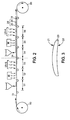
- the layered structure 30 is produced continuously on a support 31 in the form of a film (sheet).
- a production facility as represented on the figure 2 , can be used.
- the support 31 is unwound from a supply reel R0, then rolled up again on a conditioning reel R1.
- the installation comprises several sections arranged between the coils R0 and R1, to continuously form the layers 34 and 35 (optionally 33), in particular.
- a first part of the installation may comprise sections S1-S3 for continuously depositing the precursor solution of the layer 34 on the support 31 (section S1), to heat it (section S2), for example by means of an infrared radiation source disposed above the support 31, and then for polymerizing it by linearly polarized UV-B irradiation (section S3).
- a second part of the installation may comprise sections S4-S6, respectively to deposit (section S4), to heat (section S5) and to polymerize (section S6) layer 35.
- Such a continuous production facility of the layered structure 30 may comprise additional sections not shown on the figure 2 , to perform additional manufacturing steps. It may comprise in particular one or more sections for forming the peel layer 32 and / or the functional layer 33. Such sections are arranged between the supply reel R0 and the section S1.
- the solvent used to deposit the peel layer 32 may be n-propanol, when this layer comprises silicone compounds.
- the production facility of the structure 30 may also include additional sections disposed between the section S6 and the conditioning roll R1, to form the layer of adhesive material 36 and, optionally, the removable film 37.
- the production facility may optionally include rolling sections before section S1 and / or after section S6.
- the invention is described in the context of the application of the previous layer structure to an ophthalmic lens which constitutes the basic optical element. It is understood that it can be implemented in a similar manner with other optical elements, such as, in particular, a sighting instrument element, a measuring instrument element or a helmet visor.
- an ophthalmic lens 20 has a convex surface 21 and a concave surface 22. It may be made of mineral or organic material, in particular an organic material with a high refractive index.
- the term "high refractive index” means an index greater than or equal to 1.60, which may be equal to 1.67, for example.
- the use of such a high refractive index material for the production of an ametropic correction lens is particularly advantageous, since the lens can then have a reduced thickness and a lower curvature, for an identical optical power. A lower weight of the lens results, which provides greater comfort to the wearer.
- such an ophthalmic lens may have a thickness of less than 1.2 mm in a central zone thereof, or even substantially equal to 1.1 mm.
- the layered structure 30 is applied to the convex front face 21 of the lens 20 by way of example to illustrate this first method of application, but the structure 30 can be applied in a similar way to the concave posterior face 22 of the lens.
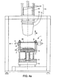
- a device as described in the patent application FR / 05 03306 and illustrated on the figure 4a can be used.
- Such a device comprises a low pressure chamber 1 and an application system 15 disposed above the enclosure via a rigid structure.
- the low-pressure chamber 1 itself comprises a lateral wall 4, for example cylindrical with a vertical axis. It is provided with a clamping ring 8, to firmly hold a membrane on the peripheral edge 4.
- the enclosure 1 is thus sealingly closed on its upper face.
- the enclosure 1 is disposed above a base 10 at a fixed height.
- a cylinder 2 of vertical axis and a piston 3 which passes through the lower face of the chamber 1 can move vertically an element holder 7 inside the enclosure 1.
- a locking system 6 allows to fix the height of the element holder 7, and the wall 4 is provided with a gas inlet 9, as well as a suction port 5.
- the orifice 5 is connected to a pumping unit not shown.
- the application system 15 comprises a buffer 11 mounted on vertical slides 13, and movable by means of a displacement system 12.
- a displacement system may comprise a stepper motor which drives a translation screw, for example.
- the layered structure 30 is fixed on the enclosure 1 by means of the ring 8. It is oriented so that the layer of adhesive material 36 is turned towards the interior of the enclosure 1, in accordance with the vertical direction oriented N which is indicated on the figures 1b and 4a . At this time, if the structure 30 includes a film 37 covering the layer 36, this film 37 is removed, for example by peeling, so as to discover the adhesive material of the layer 36.
- the lens 20 is fixed on the element holder 7, so that its face 21 is oriented upwards.
- the application of the layered structure 30 to the lens 20 can then be carried out by bringing the structure 30 and the lens 20 closer together in several steps.
- a first step the pad 11 is lowered so as to push a central portion of the structure 30 towards the inside of the enclosure 1. Since the structure 30 is held firmly on its periphery by the ring 8 , the structure 30 is deformed and takes a curved shape, which corresponds to that of the lower end of the buffer 11. When the structure 30 exhibits a plastic behavior, this first step constitutes a preforming the layered structure, so that it can then be applied regularly to the curved surface 21 of the lens 20.
- the lens 20 is approached to the layered structure 30 creating a depression between them, inside the chamber 1.
- the piston 3 rises as a gas initially present in the chamber 1 is sucked by the orifice 5.
- the height of the piston 3 is then fixed by means of the blocking 6.
- the pad 11 is again lowered by pressing it on the layered structure 30, on one side thereof opposite the lens 20.
- the structure 30 is applied on the entire surface 21 of the lens 20, with the layer of adhesive material 36 clamped therebetween.
- the end of the pad 11 is preferably made of a flexible material, so as to obtain a regular application of the structure 30 over the entire surface 21 of the lens.
- the buffer 11 is then raised, the suction in the chamber 1 is stopped and the ring 8 is unlocked.
- the lens 20 is removed from the device with the structure 30 bonded through the adhesive layer 36, on its convex face, perfectly marrying the geometry of the basic optical element, optionally, a new irradiation of the layer 35 can be performed with UV-A radiation energy of 0.5 to 5.0 J to complete the polymerization of the overall system.
- a polymerization of the entire system makes it possible to benefit from a suitable mechanical behavior of the structure 30 during its application to the ophthalmic lens.
- Such final irradiation may also make it possible to enhance the stability of the system due to an increase in the conversion rate of the constituent elements.
- a polarizing ophthalmic lens which has a high polarization efficiency is then obtained, and which has a satisfactory optical quality.
- the inventors have found that the application of the structure 30 to the lens 20 does not disturb the orientation of the dichroic dyes inside the layer 35.
- the use of a depression inside the enclosure 1 during the application of the structure 30 to the glass 20 helps to prevent a gaseous bubble being trapped involuntarily, between the layered structure and the glass.
- the layered structure 30 comprises a functional layer 33 situated within the structure, on a side opposite to the layer of adhesive material 36, the layer 33 is located on the surface of the obtained polarizing lens, on an opposite side.
- This configuration is suitable when the layer 33 has a protective function against UV radiation, a mechanical protection function, an anti-reflective function or an antifouling function.
- the portion of adhesive material which ensures the attachment of the layered structure on the base optical element may be initially arranged on this element, on the face thereof which is intended to receive the layered structure.
Landscapes
- Engineering & Computer Science (AREA)
- Manufacturing & Machinery (AREA)
- Mechanical Engineering (AREA)
- Physics & Mathematics (AREA)
- Health & Medical Sciences (AREA)
- Ophthalmology & Optometry (AREA)
- General Physics & Mathematics (AREA)
- Optics & Photonics (AREA)
- Polarising Elements (AREA)
Claims (22)
- Verfahren zum Herstellen eines optischen Polarisationselements durch Anwenden einer Schichtstruktur (30) auf eine pseudosphärische Oberfläche eines optischen Basiselements (20), wobei die Struktur eine erste orientierende Schicht (34) und eine zweite polarisierende Schicht, die ihrerseits Flüssigkristallpolymere und wenigstens einen dichroitischen Farbstoff (35) enthält, umfasst, wobei der dichroitische Farbstoff eine durch die erste Schicht bestimmte Winkelorientierung besitzt, wobei das Verfahren die folgenden Schritte umfasst:/a/ Herstellen der Schichtstruktur (30) auf einem vorläufigen Träger (31), wobei der Schritt /a/ die folgenden Unterschritte umfasst:/a1/ Bilden einer ersten Schicht (34) auf der Basis von photoorientierbaren Polymeren, die photoreaktive Gruppen aufweisen, auf dem vorläufigen Träger (31) ;/a2/ Polymerisieren der ersten Schicht (34) unter einer ersten linear polarisierten Ultraviolettstrahlung, derart, dass ein Polymernetz hergestellt wird, das in einer Richtung, die durch die Polarisationsrichtung der ersten Ultraviolettstrahlung vorgegeben ist, photoorientiert ist;/a3/ Bilden einer zweiten Schicht (35), die ein Gemisch aus dichroitischen Farbstoffen mit wenigstens einem vernetzbaren Monomer-Flüssigkristall, der durch die erste Schicht (34) in Winkelrichtung orientiert wird, enthält, auf der ersten Schicht (34); und/a4/ wenigstens teilweises Polymerisieren der Monomer-Flüssigkristalle der zweiten Schicht (35), derart, dass die dichroitischen Farbstoffe in der durch die erste Schicht bestimmten Winkelorientierung fixiert werden, indem eine Dosis einer zweiten Ultraviolettstrahlung verwendet wird, die in der Weise eingestellt ist, dass die zweite Schicht (35) unterpolymerisiert wird und eine Glasübergangstemperatur kleiner oder gleich einer Umgebungstemperatur, die um 5 °C variieren kann, besitzt;/b/ Abziehen der Schichtstruktur (30) von dem vorläufigen Träger (31), derart, dass die Struktur in Form einer selbsttragenden Membran erhalten wird; und/c/ Aufbringen der Schichtstruktur (30) auf die pseudosphärische Oberfläche des optischen Basiselements (20).
- Verfahren nach Anspruch 1, wobei die zweite Schicht (35) eine Dicke im Bereich von 3 bis 100 µm, vorzugsweise von 5 bis 50 µm und µm stärksten bevorzugt von 5 bis 10 µm, besitzt.
- Verfahren nach einem der vorhergehenden Ansprüche, das einen Schritt des zusätzlichen Polymerisierens der zweiten Schicht (35) umfasst, der nach dem Schritt /c/ ausgeführt wird, derart, dass die Polymerisation des Monomer-Flüssigkristalls beendet wird.
- Verfahren nach einem der vorhergehenden Ansprüche, wobei die Schichtstruktur (30) im Schritt /a/ in Form einer ununterbrochenen dünnen Schicht verwirklicht wird, die dann optional in Segmente zerschnitten wird, die dazu bestimmt sind, auf verschiedene optische Basiselemente (20) aufgebracht zu werden.
- Verfahren nach einem der vorhergehenden Ansprüche, wobei der vorläufige Träger (31) eine Oberflächenenergie im Bereich von 25 mN/m bis 40 mN/m, vorzugsweise von 30 mN/m bis 35 mN/m, aufweist.
- Verfahren nach Anspruch 5, wobei der vorläufige Träger (31) ein Material, das aus Polyethylen und Polypropylen gewählt ist, als Basis hat.
- Verfahren nach einem der vorhergehenden Ansprüche, wobei der Schritt /a/ außerdem das Herstellen einer Abziehschicht (32) auf dem vorläufigen Träger (31) zwischen der Schichtstruktur (30) und dem vorläufigen Träger umfasst.
- Verfahren nach Anspruch 7, wobei die Abziehschicht (32) einen oberflächenaktiven Verbund auf Silikonbasis umfasst.
- Verfahren nach einem der vorhergehenden Ansprüche, wobei der Schritt /a/ außerdem das Herstellen auf dem vorläufigen Träger (31) wenigstens einer dritten Schicht (33), die aus einer Schicht zum Schutz vor UV-Strahlung, einer Sauerstoffsperrschicht, einer Antiabriebschicht, einer Antistoßschicht, einer antireflektierenden Beschichtung, einer antistatischen Beschichtung und einer Anwuchsverhinderungsbeschichtung gewählt ist, umfasst, wobei die dritte Schicht einen Teil der Struktur (30) in Form einer selbsttragenden Membran, die im Schritt /b/ erhalten wird, bildet und sich am Ende des Schrittes /c/ auf der einen Seite der ersten (34) und der zweiten (35) Schicht gegenüber dem optischen Element (20) befindet.
- Verfahren nach einem der vorhergehenden Ansprüche, wobei im Schritt /c/ die Schichtstruktur (30) auf die Oberfläche des optischen Basiselements (20) aufgebracht wird, wobei ein Anteil eines Klebstoffmaterials (36) zwischen der Struktur und dem optischen Element angeordnet ist.
- Verfahren nach Anspruch 10, wobei der Anteil des Klebstoffmaterials (36) vor dem Schritt /c/ in Form einer Schicht auf einer Fläche des optischen Elements und/oder in Form einer zusätzlichen Schicht der Schichtstruktur (30) angeordnet wird.
- Verfahren nach Anspruch 10, wobei der Anteil des Klebstoffmaterials (36) vor dem Schritt /c/ in Form einer zusätzlichen Schicht der Schichtstruktur (30) auf einer Seite der ersten (34) und der zweiten (35) Schicht angeordnet wird.
- Verfahren nach Anspruch 12, wobei die Klebstoffmaterialschicht (36) mit einer Haut (37) innerhalb der Schichtstruktur (30) überzogen ist, wobei die Haut vor dem Schritt /c/ abgezogen wird.
- Verfahren nach einem der Ansprüche 10 bis 13, wobei das Klebstoffmaterial aus den druckempfindlichen Klebstoffen gewählt ist und wobei der Anteil des Klebstoffmaterials (36) vor dem Schritt /c/ in Form einer Schicht, die eine Dicke im Bereich von 0,5 bis 200 µm aufweist, angeordnet wird.
- Verfahren nach einem der Ansprüche 1 bis 14, das außerdem zwischen den Schritten /b/ und /c/ einen Schritt des Vorformens der Schichtstruktur (30) umfasst, der in der Weise ausgeführt wird, dass die Struktur die Form einer gekrümmten Membran hat.
- Verfahren nach Anspruch 15, wobei der Schritt /c/ die folgenden Unterschritte umfasst:/c1/ Annähern des optischen Basiselements (20) an die Schichtstruktur (30), derart, dass ein Punktkontakt zwischen der Struktur und der Oberfläche des optischen Elements verwirklicht wird; und/c2/ Pressen der Schichtstruktur (30) gegen das optische Basiselement (20), derart, dass die Struktur auf die gesamte Oberfläche des optischen Elements aufgebracht wird.
- Verfahren nach Anspruch 16, wobei der Schritt /c1/ dadurch ausgeführt wird, dass zwischen dem optischen Basiselement (20) und der Schichtstruktur (30) eine Vertiefung erzeugt wird.
- Verfahren nach Anspruch 16 oder 17, wobei der Schritt /c2/ dadurch ausgeführt wird, dass gegen die Schichtstruktur (30) von einer Seite der Struktur gegenüber dem optischen Basiselement (20) ein Dämpfungsmaterial (11) gepresst wird.
- Verfahren nach einem der Ansprüche 1 bis 14, wobei der Schritt /c/ dadurch ausgeführt wird, dass ein Fluidüberdruck auf die Schichtstruktur (30) von einer Seite der Struktur gegenüber dem optischen Basiselement (20) ausgeübt wird.
- Verfahren nach einem der vorhergehenden Ansprüche, wobei das optische Basiselement (20) ein Visierinstrument-Element, ein Messinstrument-Element, eine ophthalmische Linse oder ein Helmvisier umfasst.
- Verfahren nach Anspruch 20, wobei das optische Basiselement (20) eine ophthalmische Linse darstellt.
- Verfahren nach Anspruch 21, wobei das optische Basiselement (20) eine ophthalmische Linse darstellt, wobei ein Substrat der Linse einen Brechungsindex größer als 1,60 besitzt.
Applications Claiming Priority (1)
| Application Number | Priority Date | Filing Date | Title |
|---|---|---|---|
| FR0601612A FR2897695B1 (fr) | 2006-02-23 | 2006-02-23 | Procede de realisation d'un element optique polarisant |
Publications (2)
| Publication Number | Publication Date |
|---|---|
| EP1826595A1 EP1826595A1 (de) | 2007-08-29 |
| EP1826595B1 true EP1826595B1 (de) | 2015-10-21 |
Family
ID=37106326
Family Applications (1)
| Application Number | Title | Priority Date | Filing Date |
|---|---|---|---|
| EP07290194.5A Active EP1826595B1 (de) | 2006-02-23 | 2007-02-15 | Verfahren zur Herstellung eines polarisierenden optischen Elements |
Country Status (4)
| Country | Link |
|---|---|
| US (1) | US7632552B2 (de) |
| EP (1) | EP1826595B1 (de) |
| JP (1) | JP2007226241A (de) |
| FR (1) | FR2897695B1 (de) |
Families Citing this family (8)
| Publication number | Priority date | Publication date | Assignee | Title |
|---|---|---|---|---|
| FR2897693B1 (fr) * | 2006-02-23 | 2008-11-21 | Essilor Int | Element optique polarisant comprenant un film polariseur et procede de farbrication d'un tel element |
| EP2552267A4 (de) | 2010-03-26 | 2014-07-09 | Nat Oilwell Varco Lp | Kopfbedeckung und verfahren zu deren verwendung |
| US9901247B2 (en) * | 2013-06-28 | 2018-02-27 | Verily Life Sciences Llc | Methods for adhering a substrate to a polymer layer |
| FR3021248B1 (fr) * | 2014-05-21 | 2016-06-03 | Essilor Int | Procede de fabrication d'une lentille ophtalmique |
| FR3021247B1 (fr) * | 2014-05-21 | 2017-01-27 | Essilor Int | Procede de fabrication d'une lentille ophtalmique et cette lentille |
| EP3150364B1 (de) * | 2015-09-29 | 2018-11-14 | Essilor International | Verfahren zur herstellung einer optischen vorrichtung |
| EP3495853B1 (de) * | 2017-12-08 | 2020-07-29 | Essilor International | Zusammensetzung zur herstellung eines brillenglases mit einem verkapselten lichtabsorbierenden additiv |
| JP7260282B2 (ja) * | 2018-10-29 | 2023-04-18 | ホヤ レンズ タイランド リミテッド | 眼鏡レンズ製造装置、眼鏡レンズ製造システムおよび眼鏡レンズ製造方法 |
Family Cites Families (14)
| Publication number | Priority date | Publication date | Assignee | Title |
|---|---|---|---|---|
| US2524286A (en) * | 1946-05-14 | 1950-10-03 | John F Dreyer | Flexible noncrystalline self-contained polarizing films and methods of making and using the same |
| JPH0973015A (ja) * | 1995-09-06 | 1997-03-18 | Sumitomo Chem Co Ltd | 配向色素含有膜とその製造方法及び偏光素子と液晶表示装置 |
| GB9812636D0 (en) | 1998-06-11 | 1998-08-12 | Rolic Ag | Optical component orientation layer and layerable polymerisable mixture |
| JP2001330726A (ja) * | 2000-05-22 | 2001-11-30 | Dainippon Printing Co Ltd | 偏光素子及び偏光素子の製造方法 |
| US6630289B1 (en) * | 2000-08-22 | 2003-10-07 | The Hong Kong University Of Science And Technology | Photo-patterned light polarizing films |
| JP2002316339A (ja) * | 2001-04-20 | 2002-10-29 | Seiko Epson Corp | 偏光光学部材の製造方法 |
| US6562466B2 (en) * | 2001-07-02 | 2003-05-13 | Essilor International Compagnie Generale D'optique | Process for transferring a coating onto a surface of a lens blank |
| US7025458B2 (en) * | 2002-08-07 | 2006-04-11 | Vision-Ease Lens | Process to mold a plastic optical article with integrated hard coating |
| JP2004346093A (ja) * | 2003-03-25 | 2004-12-09 | Mitsubishi Polyester Film Copp | 光学部材表面保護フィルム用離型フィルム |
| JP2005049865A (ja) * | 2003-07-17 | 2005-02-24 | Arisawa Mfg Co Ltd | 光学位相差素子の製造方法 |
| US7097303B2 (en) | 2004-01-14 | 2006-08-29 | Ppg Industries Ohio, Inc. | Polarizing devices and methods of making the same |
| DE602004010491T2 (de) * | 2004-05-07 | 2008-11-13 | Essilor International (Compagnie Generale D'optique) | Polarisierender kratzfester optischer Film und Herstellungsverfahren hierfür |
| FR2883984B1 (fr) | 2005-04-04 | 2007-06-22 | Essilor Int | Appareil pour conformer un film plan sur une lentille optique, procedes de fonctionnalisation d'une lentille optique au moyen dudit appareil, et lentille ainsi obtenue |
| FR2897694B1 (fr) * | 2006-02-23 | 2008-05-16 | Essilor Int | Procede de realisation d'un element optique polarisant |
-
2006
- 2006-02-23 FR FR0601612A patent/FR2897695B1/fr not_active Expired - Lifetime
-
2007
- 2007-02-15 EP EP07290194.5A patent/EP1826595B1/de active Active
- 2007-02-22 JP JP2007041828A patent/JP2007226241A/ja active Pending
- 2007-02-22 US US11/677,661 patent/US7632552B2/en active Active
Also Published As
| Publication number | Publication date |
|---|---|
| US20070212518A1 (en) | 2007-09-13 |
| FR2897695B1 (fr) | 2008-06-06 |
| EP1826595A1 (de) | 2007-08-29 |
| US7632552B2 (en) | 2009-12-15 |
| FR2897695A1 (fr) | 2007-08-24 |
| JP2007226241A (ja) | 2007-09-06 |
Similar Documents
| Publication | Publication Date | Title |
|---|---|---|
| EP1826594B1 (de) | Herstellungsverfahren einer polarisierenden optischen Vorrichtung | |
| EP1987380B1 (de) | Optisches polarisierungselement mit polarisierungsfilm und herstellungsverfahren dafür | |
| EP1826595A1 (de) | Verfahren zur Herstellung eines polarisierenden optischen Elements | |
| US6886937B2 (en) | Ophthalmic lens with graded interference coating | |
| FR2918917A1 (fr) | Procede de collage d'un film sur un substrat courbe | |
| US20230314679A1 (en) | Laminated optical film and image display device | |
| US20060192306A1 (en) | Manufacturing methods for embedded optical system | |
| EP2024765A1 (de) | Platte zur änderung der leistung einer optischen komponente | |
| US20250035830A1 (en) | Forming method, optical film, cholesteric liquid crystal layer, optical laminate, and production method of curved-shaped optically functional layer | |
| US20210271011A1 (en) | Preserving In-Plane Function of Polarization Laminates in a Forming Process | |
| WO2023199988A1 (ja) | 光学機能性フィルム、光学積層体、成形体、光学部品の製造方法、光学部品、仮想現実表示装置、光学フィルムおよび成形方法 | |
| KR20070027544A (ko) | 편광 및 내마모성 광학 제품 및 이의 제조 방법 | |
| US20250298238A1 (en) | Optical laminate, laminated optical film, optical article, and virtual reality display device | |
| US20190302334A1 (en) | Phase difference film, optical film, and display device | |
| US20250321370A1 (en) | Retardation film, laminated optical film, optical article, and virtual reality display device | |
| WO2025063263A1 (ja) | 赤外光反射素子、積層光学フィルムおよび光学物品 | |
| WO2025063244A1 (ja) | 赤外光反射素子、積層光学フィルムおよび光学物品 | |
| CN120898157A (zh) | 吸光各向异性膜、层叠体、复合透镜及虚拟现实显示装置 | |
| CN120936916A (zh) | 吸光各向异性膜、层叠体、复合透镜及虚拟现实显示装置 |
Legal Events
| Date | Code | Title | Description |
|---|---|---|---|
| PUAI | Public reference made under article 153(3) epc to a published international application that has entered the european phase |
Free format text: ORIGINAL CODE: 0009012 |
|
| AK | Designated contracting states |
Kind code of ref document: A1 Designated state(s): AT BE BG CH CY CZ DE DK EE ES FI FR GB GR HU IE IS IT LI LT LU LV MC NL PL PT RO SE SI SK TR |
|
| AX | Request for extension of the european patent |
Extension state: AL BA HR MK YU |
|
| 17P | Request for examination filed |
Effective date: 20080208 |
|
| AKX | Designation fees paid |
Designated state(s): AT BE BG CH CY CZ DE DK EE ES FI FR GB GR HU IE IS IT LI LT LU LV MC NL PL PT RO SE SI SK TR |
|
| 17Q | First examination report despatched |
Effective date: 20121121 |
|
| GRAP | Despatch of communication of intention to grant a patent |
Free format text: ORIGINAL CODE: EPIDOSNIGR1 |
|
| INTG | Intention to grant announced |
Effective date: 20141215 |
|
| GRAP | Despatch of communication of intention to grant a patent |
Free format text: ORIGINAL CODE: EPIDOSNIGR1 |
|
| INTG | Intention to grant announced |
Effective date: 20150519 |
|
| GRAS | Grant fee paid |
Free format text: ORIGINAL CODE: EPIDOSNIGR3 |
|
| GRAA | (expected) grant |
Free format text: ORIGINAL CODE: 0009210 |
|
| AK | Designated contracting states |
Kind code of ref document: B1 Designated state(s): AT BE BG CH CY CZ DE DK EE ES FI FR GB GR HU IE IS IT LI LT LU LV MC NL PL PT RO SE SI SK TR |
|
| REG | Reference to a national code |
Ref country code: GB Ref legal event code: FG4D Free format text: NOT ENGLISH Ref country code: NL Ref legal event code: MP Effective date: 20151021 |
|
| REG | Reference to a national code |
Ref country code: DE Ref legal event code: R081 Ref document number: 602007043558 Country of ref document: DE Owner name: ESSILOR INTERNATIONAL, FR Free format text: FORMER OWNER: ESSILOR INTERNATIONAL COMPAGNIE GENERALE D'OPTIQUE, CHARENTON, FR |
|
| REG | Reference to a national code |
Ref country code: CH Ref legal event code: EP |
|
| REG | Reference to a national code |
Ref country code: AT Ref legal event code: REF Ref document number: 756949 Country of ref document: AT Kind code of ref document: T Effective date: 20151115 |
|
| REG | Reference to a national code |
Ref country code: IE Ref legal event code: FG4D Free format text: LANGUAGE OF EP DOCUMENT: FRENCH |
|
| REG | Reference to a national code |
Ref country code: DE Ref legal event code: R096 Ref document number: 602007043558 Country of ref document: DE |
|
| REG | Reference to a national code |
Ref country code: FR Ref legal event code: PLFP Year of fee payment: 10 |
|
| REG | Reference to a national code |
Ref country code: LT Ref legal event code: MG4D |
|
| REG | Reference to a national code |
Ref country code: AT Ref legal event code: MK05 Ref document number: 756949 Country of ref document: AT Kind code of ref document: T Effective date: 20151021 |
|
| PG25 | Lapsed in a contracting state [announced via postgrant information from national office to epo] |
Ref country code: IS Free format text: LAPSE BECAUSE OF FAILURE TO SUBMIT A TRANSLATION OF THE DESCRIPTION OR TO PAY THE FEE WITHIN THE PRESCRIBED TIME-LIMIT Effective date: 20160221 Ref country code: IT Free format text: LAPSE BECAUSE OF FAILURE TO SUBMIT A TRANSLATION OF THE DESCRIPTION OR TO PAY THE FEE WITHIN THE PRESCRIBED TIME-LIMIT Effective date: 20151021 Ref country code: LT Free format text: LAPSE BECAUSE OF FAILURE TO SUBMIT A TRANSLATION OF THE DESCRIPTION OR TO PAY THE FEE WITHIN THE PRESCRIBED TIME-LIMIT Effective date: 20151021 Ref country code: ES Free format text: LAPSE BECAUSE OF FAILURE TO SUBMIT A TRANSLATION OF THE DESCRIPTION OR TO PAY THE FEE WITHIN THE PRESCRIBED TIME-LIMIT Effective date: 20151021 Ref country code: NL Free format text: LAPSE BECAUSE OF FAILURE TO SUBMIT A TRANSLATION OF THE DESCRIPTION OR TO PAY THE FEE WITHIN THE PRESCRIBED TIME-LIMIT Effective date: 20151021 |
|
| PG25 | Lapsed in a contracting state [announced via postgrant information from national office to epo] |
Ref country code: FI Free format text: LAPSE BECAUSE OF FAILURE TO SUBMIT A TRANSLATION OF THE DESCRIPTION OR TO PAY THE FEE WITHIN THE PRESCRIBED TIME-LIMIT Effective date: 20151021 Ref country code: SE Free format text: LAPSE BECAUSE OF FAILURE TO SUBMIT A TRANSLATION OF THE DESCRIPTION OR TO PAY THE FEE WITHIN THE PRESCRIBED TIME-LIMIT Effective date: 20151021 Ref country code: AT Free format text: LAPSE BECAUSE OF FAILURE TO SUBMIT A TRANSLATION OF THE DESCRIPTION OR TO PAY THE FEE WITHIN THE PRESCRIBED TIME-LIMIT Effective date: 20151021 Ref country code: GR Free format text: LAPSE BECAUSE OF FAILURE TO SUBMIT A TRANSLATION OF THE DESCRIPTION OR TO PAY THE FEE WITHIN THE PRESCRIBED TIME-LIMIT Effective date: 20160122 Ref country code: PT Free format text: LAPSE BECAUSE OF FAILURE TO SUBMIT A TRANSLATION OF THE DESCRIPTION OR TO PAY THE FEE WITHIN THE PRESCRIBED TIME-LIMIT Effective date: 20160222 Ref country code: BE Free format text: LAPSE BECAUSE OF NON-PAYMENT OF DUE FEES Effective date: 20160229 Ref country code: PL Free format text: LAPSE BECAUSE OF FAILURE TO SUBMIT A TRANSLATION OF THE DESCRIPTION OR TO PAY THE FEE WITHIN THE PRESCRIBED TIME-LIMIT Effective date: 20151021 Ref country code: LV Free format text: LAPSE BECAUSE OF FAILURE TO SUBMIT A TRANSLATION OF THE DESCRIPTION OR TO PAY THE FEE WITHIN THE PRESCRIBED TIME-LIMIT Effective date: 20151021 |
|
| REG | Reference to a national code |
Ref country code: DE Ref legal event code: R097 Ref document number: 602007043558 Country of ref document: DE |
|
| PG25 | Lapsed in a contracting state [announced via postgrant information from national office to epo] |
Ref country code: CZ Free format text: LAPSE BECAUSE OF FAILURE TO SUBMIT A TRANSLATION OF THE DESCRIPTION OR TO PAY THE FEE WITHIN THE PRESCRIBED TIME-LIMIT Effective date: 20151021 |
|
| PLBE | No opposition filed within time limit |
Free format text: ORIGINAL CODE: 0009261 |
|
| STAA | Information on the status of an ep patent application or granted ep patent |
Free format text: STATUS: NO OPPOSITION FILED WITHIN TIME LIMIT |
|
| PG25 | Lapsed in a contracting state [announced via postgrant information from national office to epo] |
Ref country code: DK Free format text: LAPSE BECAUSE OF FAILURE TO SUBMIT A TRANSLATION OF THE DESCRIPTION OR TO PAY THE FEE WITHIN THE PRESCRIBED TIME-LIMIT Effective date: 20151021 Ref country code: RO Free format text: LAPSE BECAUSE OF FAILURE TO SUBMIT A TRANSLATION OF THE DESCRIPTION OR TO PAY THE FEE WITHIN THE PRESCRIBED TIME-LIMIT Effective date: 20151021 Ref country code: EE Free format text: LAPSE BECAUSE OF FAILURE TO SUBMIT A TRANSLATION OF THE DESCRIPTION OR TO PAY THE FEE WITHIN THE PRESCRIBED TIME-LIMIT Effective date: 20151021 Ref country code: SK Free format text: LAPSE BECAUSE OF FAILURE TO SUBMIT A TRANSLATION OF THE DESCRIPTION OR TO PAY THE FEE WITHIN THE PRESCRIBED TIME-LIMIT Effective date: 20151021 |
|
| 26N | No opposition filed |
Effective date: 20160722 |
|
| PG25 | Lapsed in a contracting state [announced via postgrant information from national office to epo] |
Ref country code: MC Free format text: LAPSE BECAUSE OF FAILURE TO SUBMIT A TRANSLATION OF THE DESCRIPTION OR TO PAY THE FEE WITHIN THE PRESCRIBED TIME-LIMIT Effective date: 20151021 Ref country code: LU Free format text: LAPSE BECAUSE OF FAILURE TO SUBMIT A TRANSLATION OF THE DESCRIPTION OR TO PAY THE FEE WITHIN THE PRESCRIBED TIME-LIMIT Effective date: 20160215 |
|
| REG | Reference to a national code |
Ref country code: CH Ref legal event code: PL |
|
| PG25 | Lapsed in a contracting state [announced via postgrant information from national office to epo] |
Ref country code: CH Free format text: LAPSE BECAUSE OF NON-PAYMENT OF DUE FEES Effective date: 20160229 Ref country code: LI Free format text: LAPSE BECAUSE OF NON-PAYMENT OF DUE FEES Effective date: 20160229 |
|
| PG25 | Lapsed in a contracting state [announced via postgrant information from national office to epo] |
Ref country code: SI Free format text: LAPSE BECAUSE OF FAILURE TO SUBMIT A TRANSLATION OF THE DESCRIPTION OR TO PAY THE FEE WITHIN THE PRESCRIBED TIME-LIMIT Effective date: 20151021 |
|
| REG | Reference to a national code |
Ref country code: IE Ref legal event code: MM4A |
|
| PG25 | Lapsed in a contracting state [announced via postgrant information from national office to epo] |
Ref country code: IE Free format text: LAPSE BECAUSE OF NON-PAYMENT OF DUE FEES Effective date: 20160215 |
|
| REG | Reference to a national code |
Ref country code: FR Ref legal event code: PLFP Year of fee payment: 11 |
|
| REG | Reference to a national code |
Ref country code: FR Ref legal event code: PLFP Year of fee payment: 12 |
|
| REG | Reference to a national code |
Ref country code: DE Ref legal event code: R081 Ref document number: 602007043558 Country of ref document: DE Owner name: ESSILOR INTERNATIONAL, FR Free format text: FORMER OWNER: ESSILOR INTERNATIONAL (COMPAGNIE GENERALE D'OPTIQUE), CHARENTON-LE-PONT, FR |
|
| PG25 | Lapsed in a contracting state [announced via postgrant information from national office to epo] |
Ref country code: HU Free format text: LAPSE BECAUSE OF FAILURE TO SUBMIT A TRANSLATION OF THE DESCRIPTION OR TO PAY THE FEE WITHIN THE PRESCRIBED TIME-LIMIT; INVALID AB INITIO Effective date: 20070215 Ref country code: CY Free format text: LAPSE BECAUSE OF FAILURE TO SUBMIT A TRANSLATION OF THE DESCRIPTION OR TO PAY THE FEE WITHIN THE PRESCRIBED TIME-LIMIT Effective date: 20151021 |
|
| REG | Reference to a national code |
Ref country code: GB Ref legal event code: 732E Free format text: REGISTERED BETWEEN 20180517 AND 20180523 |
|
| PG25 | Lapsed in a contracting state [announced via postgrant information from national office to epo] |
Ref country code: TR Free format text: LAPSE BECAUSE OF FAILURE TO SUBMIT A TRANSLATION OF THE DESCRIPTION OR TO PAY THE FEE WITHIN THE PRESCRIBED TIME-LIMIT Effective date: 20151021 |
|
| REG | Reference to a national code |
Ref country code: FR Ref legal event code: TP Owner name: ESSILOR INTERNATIONAL, FR Effective date: 20180601 |
|
| PG25 | Lapsed in a contracting state [announced via postgrant information from national office to epo] |
Ref country code: BG Free format text: LAPSE BECAUSE OF FAILURE TO SUBMIT A TRANSLATION OF THE DESCRIPTION OR TO PAY THE FEE WITHIN THE PRESCRIBED TIME-LIMIT Effective date: 20151021 |
|
| P01 | Opt-out of the competence of the unified patent court (upc) registered |
Effective date: 20230525 |
|
| PGFP | Annual fee paid to national office [announced via postgrant information from national office to epo] |
Ref country code: GB Payment date: 20260227 Year of fee payment: 20 |
|
| PGFP | Annual fee paid to national office [announced via postgrant information from national office to epo] |
Ref country code: DE Payment date: 20260227 Year of fee payment: 20 |
|
| PGFP | Annual fee paid to national office [announced via postgrant information from national office to epo] |
Ref country code: FR Payment date: 20260225 Year of fee payment: 20 |