EP1826530B1 - Procédé et dispositif destinés à la détection de la dimension d'une roue - Google Patents
Procédé et dispositif destinés à la détection de la dimension d'une roue Download PDFInfo
- Publication number
- EP1826530B1 EP1826530B1 EP07001262A EP07001262A EP1826530B1 EP 1826530 B1 EP1826530 B1 EP 1826530B1 EP 07001262 A EP07001262 A EP 07001262A EP 07001262 A EP07001262 A EP 07001262A EP 1826530 B1 EP1826530 B1 EP 1826530B1
- Authority
- EP
- European Patent Office
- Prior art keywords
- wheel
- vehicle
- circumference
- rotational speed
- yaw rate
- Prior art date
- Legal status (The legal status is an assumption and is not a legal conclusion. Google has not performed a legal analysis and makes no representation as to the accuracy of the status listed.)
- Not-in-force
Links
Images
Classifications
-
- G—PHYSICS
- G01—MEASURING; TESTING
- G01B—MEASURING LENGTH, THICKNESS OR SIMILAR LINEAR DIMENSIONS; MEASURING ANGLES; MEASURING AREAS; MEASURING IRREGULARITIES OF SURFACES OR CONTOURS
- G01B21/00—Measuring arrangements or details thereof, where the measuring technique is not covered by the other groups of this subclass, unspecified or not relevant
- G01B21/10—Measuring arrangements or details thereof, where the measuring technique is not covered by the other groups of this subclass, unspecified or not relevant for measuring diameters
- G01B21/12—Measuring arrangements or details thereof, where the measuring technique is not covered by the other groups of this subclass, unspecified or not relevant for measuring diameters of objects while moving
-
- B—PERFORMING OPERATIONS; TRANSPORTING
- B60—VEHICLES IN GENERAL
- B60C—VEHICLE TYRES; TYRE INFLATION; TYRE CHANGING; CONNECTING VALVES TO INFLATABLE ELASTIC BODIES IN GENERAL; DEVICES OR ARRANGEMENTS RELATED TO TYRES
- B60C23/00—Devices for measuring, signalling, controlling, or distributing tyre pressure or temperature, specially adapted for mounting on vehicles; Arrangement of tyre inflating devices on vehicles, e.g. of pumps or of tanks; Tyre cooling arrangements
- B60C23/06—Signalling devices actuated by deformation of the tyre, e.g. tyre mounted deformation sensors or indirect determination of tyre deformation based on wheel speed, wheel-centre to ground distance or inclination of wheel axle
- B60C23/061—Signalling devices actuated by deformation of the tyre, e.g. tyre mounted deformation sensors or indirect determination of tyre deformation based on wheel speed, wheel-centre to ground distance or inclination of wheel axle by monitoring wheel speed
Definitions
- the invention relates to a method and a device for determining the circumference of vehicle wheels.
- the DE 103 06 498 describes a method for determining the wear on a tread of a vehicle wheel, wherein repeatedly a taking place while the vehicle vehicle revolution of the wheel and thereby actually occurring vehicle movement are evaluated and combined on a substrate.
- driver assistance systems can also provide more accurate results with accurate wheel circumferences, especially when accurate vehicle position determination is required.
- driver assistance systems include, for example, a parking aid which has to precisely measure a parking space or which enters a parking space along a desired path.
- the object of the present invention is to accurately determine the circumference of a wheel of a vehicle.
- this object is achieved by a method for determining the circumference of a wheel according to claim 1 and a device for determining the circumference of a wheel of a vehicle according to claim 10.
- the dependent claims define preferred and advantageous embodiments of the invention.
- the yaw rate is understood as meaning an angular velocity of a rotation of the vehicle about its vertical axis or yaw axis.
- the vertical axis or yaw axis is a vertical axis through the center of gravity of the vehicle, around which the vehicle turns during steering movements on a drive.
- the yaw rate and the first and second rotational speeds are measured values which change with time and can be determined, for example, via an ESP control device of the vehicle.
- the circumference of the wheel of the vehicle can also be determined relatively easily. It is particularly advantageous that the exact determination of the circumference of the wheel without external aids, such as satellite (GPS), is made possible, so that the determination is thus dynamic only with the vehicle usually already existing sensors. By accurately determining the scope then again a very accurate speed and position determination is possible.
- GPS satellite
- cornering is present when the yaw rate is significantly different from 0 ° / s and e.g. above 15 ° / s.
- the ratio X 1 between the circumference of the first wheel and the circumference of the second wheel can be determined in each case at a time at which the yaw rate integrated over a predetermined time interval has the value 0 °.
- each of the yaw rate, the first rotational speed, and the second rotational speed is started to be integrated. If, at a second time, which is later than the first time, the time integral of the yaw rate has the value 0 °, the ratio X 1 is determined from the equation (2). In this case, both the first and the second rotational speed have been integrated over a time interval which runs from the first to the second time point.
- the ratio X 1 between the circumference of the first wheel and the circumference of the second wheel can also be in a straight ahead of the vehicle from the first Determine the rotation speed DG 1 and the second rotation speed DG 2 by integrating the first rotation speed DG 1 and the second rotation speed DG 2 in time when traveling straight ahead, as indicated by the above formula (2).
- the circumference for each wheel of the vehicle may be determined depending on the yaw rate, the distance and a rotational speed for each wheel of the vehicle. This makes it possible, for example, to detect differences between the circumferences of different wheels of a vehicle and to detect, for example, wear of a wheel or air pressure fluctuations of a wheel.
- This is understood to mean a toe-in angle of a turned-in wheel of the vehicle under a steering angle.
- the steering angle is usually measured on the inside wheel and refers to the vehicle longitudinal center axis.
- the ratio X 1 may advantageously to new conditions, including a decline in tire pressure be adjusted.
- the ratio X1 can generally be determined more accurately, the longer the straight-ahead driving lasts or the more straight-ahead driving sections can be integrated continuously.
- the circumference U can, as a rule, be determined more precisely the more times N are included in the calculation.
- the calculation has to be rewritten from time to time to quickly notice changes caused, for example, by a decrease in tire pressure.
- This yaw rate correction size ⁇ kor to determine which one yaw rate measurand ⁇ Measurement, which is measured for example by the ESP control unit of the vehicle is corrected to that of yaw rate ⁇ determine with which finally the circumference of the first wheel and thus the peripheries of all the wheels of the vehicle can be accurately determined.
- This yaw rate correction quantity ⁇ kor is determined by the following formula at N times at which the vehicle is stationary, taking advantage of the fact that the yaw rate takes the value 0 when the vehicle is stationary.
- ⁇ kor ⁇ 1 N ⁇ measuring - 0 N ,
- the yaw rate correction variable can either be redetermined or determined at each new standstill of the vehicle by the averaging is continued continuously according to equation (4).
- the values given above for the boundary conditions may depend on the vehicle type. These values are usually determined for a particular vehicle type by vehicle tests. This applies both to the boundary conditions for determining the ratio X 1 between the circumference of the first and second wheels and to the boundary conditions for the precise determination of the circumference of the first wheel.
- the determination of the exact circumference of the other wheel may not necessarily be made in straight ahead travel, but may instead be performed at a time when a time integral of the yaw rate is 0 °.
- the wheel speed is calculated from a product of rotational speed and Normradun.
- a first wheel rotation speed is used instead of the second rotation speed at a second wheel rotation speed and a wheel rotation speed per wheel is used in the above equations (1) - (3) and (5).
- the use of the wheel rotational speed may have advantages when the wheel rotational speeds for the respective wheels, for which the exact circumference is to be determined, are already known, for example in an ESP control unit.
- the Normradun is a constant and corresponds in particular to a specification of the wheel manufacturer.
- the ESP control unit can be aware of the yaw rate ⁇ , the first V 1 and second V 2 wheel speed according to the invention determine the exact circumference U of the first wheel and based on the exact perimeters of the other wheels
- a device for accurately determining the circumference of a wheel of a vehicle having at least two wheels.
- the device determines the yaw rate of the vehicle and the first rotational speed of the first wheel and the second rotational speed of the second wheel of the vehicle and knows the track between the first and the second wheel.
- the device then the exact circumference of the first wheel according to the method described above.
- the present invention provides a vehicle comprising the above-described inventive device.
- the invention is preferably suitable for use in a motor vehicle. However, it is not limited to this preferred field of application, but may generally be applied to all devices having at least two wheels, such as e.g. Aircraft or trailers.
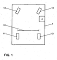
- Fig. 1 is a schematic representation of a vehicle according to the invention with a device according to the invention for determining the exact perimeters of the wheels of the vehicle.
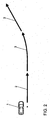
- Fig. 2 is a schematic representation showing a vehicle according to the invention and a track to be traveled by this vehicle.
- Fig. 1 schematically a vehicle 1 with four wheels 11-14 and a device 4 for determining the exact circumference of each wheel 11-14 is shown.
- the reference numeral 10 denotes the track width, ie the distance between the two rear wheels 11-12 of the vehicle 1.
- the device 4 eg an ESP control device, is able to determine the exact circumferences of the two rear wheels 11-12 on the basis of the measured variables of the first rotational speed of the first wheel 11 and the second rotational speed of the second wheel 12 and of the yaw rate of the vehicle. if the device 4, the track 10 is known.
- Fig. 2 With the help of Fig. 2 is described below how the device 4 on the in Fig. 2 illustrated track, which consists of two straight sections 2 and a curve section 3, the exact perimeters of the two rear wheels 11-12 and finally also determines the front wheels 13, 14 of the vehicle.
- a yaw rate correction quantity is calculated from the yaw rate measure, i. the yaw rate measured, since the yaw rate for a stationary vehicle by definition must be 0.
- the yaw rate measurand is corrected on the following driveway to determine the yaw rate with which, finally, the exact circumference of each wheel of the vehicle 1 is determined.
- the ratio X 1 between the circumference of the first wheel and the circumference of the second wheel is determined by integrating both the first rotational speed DG 1 of the first wheel and the second rotational speed DG 2 of the second wheel the vehicle 1 is traveling on the first straight section 2.
- the ratio X 1 between the circumference of the first wheel and the circumference of the second wheel is determined, as also described in advance with Equation (2).
- the exact circumference U of the first wheel 11 becomes dependent on the first rotation speed DG 1 of the first wheel 11, the second rotation speed DG 2 of the second wheel 12 and the yaw rate ⁇ with the aid of the track width 10 or 5 and the pre-calculated ratio X 1 between the circumference of the first wheel 11 and the circumference of the second wheel 12 at N different times determined and finally the exact circumference U of the first wheel 11 with reference to the above-described equation (1) or (3) determined.
- the peripheries of the remaining wheels 12-14 are determined from the now known exact circumference of the first wheel 11 and the rotational speeds of the four wheels 11-14 by the equation (5) described above.
- the rotational speeds of the four wheels 11-14 are determined and integrated via the ESP control unit.
- the integrated first rotational speeds are divided by the integrated rotational speeds of the particular wheel and the result multiplied by the predetermined exact circumference of the first wheel, resulting in the exact circumference of the particular wheel, as above in equation (5).
- the straight sections and the at least one curve section can, of course, also be taken from a normal route of a vehicle in which this determination is carried out.
- the rolling circumference of each wheel of a vehicle can be determined precisely.
- the distance covered by the vehicle can be determined very precisely, which is of great advantage, for example, for driver assistance systems (navigation system, parking aid).
- this can warn, for example, of a sinking air pressure or wear of a wheel, if the determined for this wheel circumference drops below a corresponding predetermined value.
Landscapes
- Physics & Mathematics (AREA)
- General Physics & Mathematics (AREA)
- Engineering & Computer Science (AREA)
- Mechanical Engineering (AREA)
- Control Of Driving Devices And Active Controlling Of Vehicle (AREA)
- Measuring Fluid Pressure (AREA)
- Steering Control In Accordance With Driving Conditions (AREA)
Claims (14)
- Procédé pour déterminer la circonférence d'une première roue (11) d'un véhicule (1) comprenant deux roues (11, 12) espacées de l'écartement des roues (10) du véhicule (1) à partir de la vitesse de rotation DG1 de la première roue (11), caractérisé en ce que la circonférence U de la première roue (11) est en plus calculée en fonction de la vitesse de rotation de la deuxième roue (11), du taux de lacet
Ψ̇ du véhicule (1), de l'écartement des roues S et du rapport X1 entre la circonférence de la première roue (11) et la circonférence de la deuxième roue (12) avec la formule
le rapport X1 étant déterminé soit par la formule suivante à partir d'une première intégrale dans le temps de la première vitesse de rotation DG1 et d'une deuxième intégrale dans le temps de la deuxième vitesse de rotation DG2 à un instant où une troisième intégrale dans le temps du taux de lacet donne la valeur 0°, les trois intégrales étant calculées sur le même intervalle de temps :
- Procédé selon la revendication 1, caractérisé en ce que le rapport X1 lors d'un déplacement en ligne droite est déterminé par la formule suivante à partir de la première intégrale dans le temps de la première vitesse de rotation DG1 et de la deuxième intégrale dans le temps de la deuxième vitesse de rotation DG2 :

- Procédé selon la revendication 1 ou 2, caractérisé en ce que la circonférence est calculée de la manière suivante en calculant la valeur moyenne sur N instants :

- Procédé selon l'une des revendications précédentes, caractérise en ce que la circonférence n'est déterminée que lorsque le taux de lacet est supérieur à 15°/s.
- Procédé selon l'une des revendications précédentes, caractérisé en ce que le rapport X1 n'est déterminé que lorsque les conditions suivantes sont remplies :- la valeur d'un angle de direction du véhicule est inférieure à 0,5°,- une vitesse du véhicule est supérieure à 10 km/h et inférieure à 50 km/h,- la valeur d'une accélération transversale du véhicule est inférieure à 1 m/s/s,- la valeur d'une accélération du véhicule est inférieure à 1 m/s2,- aucune intervention automatique du véhicule qui influence unilatéralement la première ou la deuxième vitesse de rotation.
- Procédé selon l'une des revendications précédentes, caractérisé en ce que le rapport X1 est continuellement recalculé.
- Procédé selon l'une des revendications précédentes, caractérisé en ce que le taux de lacet est déterminé en fonction d'un grandeur mesurée du taux de lacet
Ψ̇ Mess qui est corrigée au moyen d'une grandeur de correction du taux de lacetΨ kor, la grandeur de correction du taux de lacetΨ kor étant calculée par le biais de la formule suivante en fonction de la grandeur mesurée du taux de lacetΨ Mess à l'arrêt du véhicule (1), N désignant un nombre d'instants auxquels est déterminée la grandeur mesurée du taux de lacetΨ Mess :
- Procédé selon l'une des revendications précédentes, caractérisé en ce que la circonférence U n'est déterminée que lorsque les conditions suivantes sont remplies :- la valeur d'un angle de direction du véhicule (1) est supérieure à 3°,- une vitesse du véhicule (1) est supérieure à 10 km/h et inférieure à 50 km/h,- la valeur d'une accélération transversale du véhicule (1) est inférieure à 1 m/s2,- aucune intervention automatique du véhicule (1) qui influence unilatéralement la première ou la deuxième vitesse de rotation.
- Procédé selon l'une des revendications précédentes, caractérisé en ce qu'une circonférence Ua d'une autre roue (12 - 14) que la première roue (11) du véhicule (1) est calculée en fonction d'une autre vitesse de rotation DGa de l'autre roue (12 - 14), de la première vitesse de rotation DG1 et de la circonférence U1 de la première roue par la formule suivante, l'autre vitesse de rotation DGa et la première vitesse de rotation DG1 étant déterminées lors d'un déplacement du véhicule (1) en ligne droite :

- Procédé selon l'une des revendications précédentes, caractérisé en ce qu'une vitesse de rotation de roue est utilisée à la place de la vitesse de rotation, la vitesse de rotation de roue étant calculée à partir d'un produit de la vitesse de rotation par une circonférence de roue normalisée.
- Dispositif pour déterminer la circonférence d'une première roue (11) d'un véhicule (1) comprenant deux roues (11, 12) espacées de l'écartement des roues (10) du véhicule (1), le dispositif (4) étant configuré de telle sorte que le dispositif (4) calcule la circonférence de la première roue (11) en fonction de la vitesse de rotation DG1 de la première roue (11), de la vitesse de rotation de la deuxième roue (11), du taux de lacet
Ψ du véhicule (1), de l'écartement des roues S et du rapport X1 entre la circonférence de la première roue (11) et la circonférence de la deuxième roue (12) avec la formule
le dispositif (4) déterminant le rapport X1 soit par la formule suivante à partir d'une première intégrale dans le temps de la première vitesse de rotation DG1 et d'une deuxième intégrale dans le temps de la deuxième vitesse de rotation DG2 à un instant auquel le dispositif (4) calcule une troisième intégrale dans le temps du taux de lacet avec la valeur 0°, le dispositif calculant les trois intégrales sur le même intervalle de temps :
- Dispositif selon la revendication 11, le dispositif (4) déterminant le rapport X1 lors d'un déplacement en ligne droite par la formule suivante à partir de la première intégrale dans le temps de la première vitesse de rotation DG1 et de la deuxième intégrale dans le temps de la deuxième vitesse de rotation DG2 :

- Dispositif selon la revendication 11 ou 12, caractérisé en ce que le dispositif (4) est configuré pour mettre en oeuvre le procédé selon l'une des revendications 3 à 10.
- Véhicule équipé d'un dispositif selon l'une des revendications 11 à 13.
Applications Claiming Priority (2)
| Application Number | Priority Date | Filing Date | Title |
|---|---|---|---|
| DE102006008623 | 2006-02-24 | ||
| DE102006020490A DE102006020490A1 (de) | 2006-02-24 | 2006-04-28 | Verfahren und Vorrichtung zur Umfangsermittlung von Fahrzeugrädern |
Publications (2)
| Publication Number | Publication Date |
|---|---|
| EP1826530A1 EP1826530A1 (fr) | 2007-08-29 |
| EP1826530B1 true EP1826530B1 (fr) | 2008-08-27 |
Family
ID=37912462
Family Applications (1)
| Application Number | Title | Priority Date | Filing Date |
|---|---|---|---|
| EP07001262A Not-in-force EP1826530B1 (fr) | 2006-02-24 | 2007-01-20 | Procédé et dispositif destinés à la détection de la dimension d'une roue |
Country Status (3)
| Country | Link |
|---|---|
| EP (1) | EP1826530B1 (fr) |
| AT (1) | ATE406563T1 (fr) |
| DE (2) | DE102006020490A1 (fr) |
Cited By (6)
| Publication number | Priority date | Publication date | Assignee | Title |
|---|---|---|---|---|
| DE102012018000B3 (de) * | 2012-09-12 | 2013-11-07 | Volkswagen Aktiengesellschaft | Verfahren zur Ermittlung des relativen Radabrollumfangsverhältnisses |
| DE102013004900A1 (de) | 2013-03-21 | 2014-09-25 | Valeo Schalter Und Sensoren Gmbh | Verfahren zum Bestimmen eines aktuellen Umfangs eines Rades eines Kraftfahrzeugs, Fahrerassistenzeinrichtung und Kraftfahrzeug |
| EP2886422A2 (fr) | 2013-12-21 | 2015-06-24 | Valeo Schalter und Sensoren GmbH | Procédé de détermination d'un angle de direction réel d'un véhicule automobile, dispositif d'assistance au conducteur et véhicule automobile |
| DE102016223902A1 (de) | 2016-12-01 | 2018-06-07 | Audi Ag | Verfahren und System zur Bestimmung von Radumfängen und Spurweiten eines Fahrzeugs |
| DE102018116512A1 (de) | 2018-07-09 | 2020-01-09 | Valeo Schalter Und Sensoren Gmbh | Neue odometrische Berechnungen für eine Eigenbewegung eines Kraftfahrzeugs auf Basis einer Abschätzung von Steifigkeitskoeffizienten |
| DE102018117945A1 (de) * | 2018-07-25 | 2020-01-30 | Valeo Schalter Und Sensoren Gmbh | Neuartiger Ansatz zur Ermittlung eines Radumfangs eines fahrenden Kraftfahrzeugs |
Families Citing this family (15)
| Publication number | Priority date | Publication date | Assignee | Title |
|---|---|---|---|---|
| DE102010000867A1 (de) * | 2010-01-13 | 2011-07-14 | Robert Bosch GmbH, 70469 | Verfahren zur Ermittlung eines aktualisierten Radumfangs |
| DE102010006178B4 (de) * | 2010-01-29 | 2019-02-21 | Continental Automotive Gmbh | Verfahren zur Überwachung eines Reifendrucks und Reifendruckkontrolleinrichtung |
| DE102010038971A1 (de) * | 2010-08-05 | 2012-02-09 | Robert Bosch Gmbh | Verfahren und Vorrichtung zum Bewerten eines Zustands eines Fahrwerks eines Fahrzeugs |
| DE102011115668A1 (de) | 2011-09-28 | 2013-03-28 | GM Global Technology Operations LLC (n. d. Gesetzen des Staates Delaware) | Verfahren zum Ermitteln einer Geschwindigkeit eines Fahrzeugs und Fahrzeug |
| DE102012208298A1 (de) * | 2012-05-16 | 2013-11-21 | Robert Bosch Gmbh | Verfahren und Vorrichtung zum Ermitteln des Umfanges eines an einem Fahrzeug verbauten Reifens |
| DE102012023021A1 (de) * | 2012-11-26 | 2014-05-28 | GM Global Technology Operations LLC (n. d. Ges. d. Staates Delaware) | Verfahren zur Ermittlung eines Reifenprofilwertes innerhalb eines Fahrbetriebes eines Kraftfahrzeugs |
| DE102013108285A1 (de) | 2013-08-01 | 2015-02-05 | Scania Cv Ab | Verfahren und System zur Bestimmung einer Druckabweichung zwischen einem Sollreifendruck und einem aktuellen Reifendruck für einen Reifen eines Fahrzeugs sowie zur Bestimmung einer Radlast |
| DE102013108283A1 (de) | 2013-08-01 | 2015-02-05 | Scania Cv Ab | Verfahren und System zur Bestimmung eines Druckverhältnisses zwischen einem Sollreifendruck und einem aktuellen Reifendruck für einen Reifen eines Fahrzeugs |
| FR3014366B1 (fr) | 2013-12-05 | 2016-01-08 | Continental Automotive France | Procede de determination de l'empreinte d'un pneumatique de roue sur le sol |
| DE102016010750B4 (de) | 2016-09-06 | 2018-07-12 | Nira Dynamics Ab | Schätzung absoluter Radrollradien und Schätzung eines vertikalen Kompressionswerts |
| DE102018115043A1 (de) | 2018-06-22 | 2019-12-24 | Thyssenkrupp Ag | Verfahren zur Ermittlung eines Radumfanges anhand der gemessenen Gierrate |
| DE102018123092A1 (de) * | 2018-09-20 | 2020-03-26 | Valeo Schalter Und Sensoren Gmbh | Verfahren zum Bestimmen einer lateralen Geschwindigkeit sowie einer Gierrate für eine Eigenbewegung eines Kraftfahrzeugs |
| DE102018222152A1 (de) * | 2018-12-18 | 2020-06-18 | Robert Bosch Gmbh | Verfahren und Vorrichtung zum Ermitteln eines dynamischen Reifenumfangs eines Fortbewegungsmittels |
| DE102019110805B4 (de) * | 2019-04-26 | 2021-06-24 | Schaeffler Technologies AG & Co. KG | Verfahren zur Bestimmung einer tatsächlichen Reifengröße der Reifen eines Fahrzeuges |
| DE102021211169B4 (de) * | 2021-10-04 | 2023-05-11 | Continental Automotive Technologies GmbH | Reifenumfangsbestimmung für angetriebene Achsen |
Family Cites Families (10)
| Publication number | Priority date | Publication date | Assignee | Title |
|---|---|---|---|---|
| DE3236520A1 (de) * | 1982-10-02 | 1984-04-05 | Robert Bosch Gmbh, 7000 Stuttgart | Einrichtung zum anzeigen des zustandes von fahrzeugreifen |
| DE59914189D1 (de) * | 1998-08-08 | 2007-03-29 | Volkswagen Ag | Verfahren zur Bestimmung des Kurvenradius einer Fahrbahn |
| US6817236B1 (en) * | 1999-06-19 | 2004-11-16 | Continental Teves Ag & Co., Ohg | Method and device for creating a compensation value table for determining a test variable, and for identifying the pressure loss in a tire of a wheel |
| DE10024178A1 (de) * | 2000-05-17 | 2001-12-06 | Wabco Gmbh & Co Ohg | Verfahren zur verbesserten Bestimmung des Verhältnisses der Radien der Räder eines Fahrzeuges zueinander |
| JP2002107371A (ja) * | 2000-09-29 | 2002-04-10 | Toyota Motor Corp | 車輪の回転状態検出装置 |
| DE10058099A1 (de) * | 2000-11-09 | 2002-05-23 | Continental Teves Ag & Co Ohg | Verfahren und Vorrichtung zum Erkennen oder Abschätzen von Reifenabnutzung |
| US7676307B2 (en) * | 2001-11-05 | 2010-03-09 | Ford Global Technologies | System and method for controlling a safety system of a vehicle in response to conditions sensed by tire sensors related applications |
| DE10306498A1 (de) * | 2003-02-17 | 2004-08-26 | Bayerische Motoren Werke Ag | Bestimmung der Abnutzung an einer Lauffläche eines Fahrzeug-Rades |
| DE602004019175D1 (de) * | 2003-10-27 | 2009-03-12 | Sumitomo Rubber Ind | Verfahren und Vorrichtung zum Detektieren eines Druckabfalls im Reifen |
| US20070283750A1 (en) * | 2004-04-07 | 2007-12-13 | Continental Teves Ag & Co. Ohg | Tire Sensitivity Recognition Method |
-
2006
- 2006-04-28 DE DE102006020490A patent/DE102006020490A1/de not_active Ceased
-
2007
- 2007-01-20 DE DE502007000082T patent/DE502007000082D1/de active Active
- 2007-01-20 AT AT07001262T patent/ATE406563T1/de not_active IP Right Cessation
- 2007-01-20 EP EP07001262A patent/EP1826530B1/fr not_active Not-in-force
Cited By (9)
| Publication number | Priority date | Publication date | Assignee | Title |
|---|---|---|---|---|
| DE102012018000B3 (de) * | 2012-09-12 | 2013-11-07 | Volkswagen Aktiengesellschaft | Verfahren zur Ermittlung des relativen Radabrollumfangsverhältnisses |
| DE102013004900A1 (de) | 2013-03-21 | 2014-09-25 | Valeo Schalter Und Sensoren Gmbh | Verfahren zum Bestimmen eines aktuellen Umfangs eines Rades eines Kraftfahrzeugs, Fahrerassistenzeinrichtung und Kraftfahrzeug |
| WO2014146821A1 (fr) | 2013-03-21 | 2014-09-25 | Valeo Schalter Und Sensoren Gmbh | Procédé permettant de déterminer la portée actuelle d'une roue d'un véhicule automobile, dispositif d'aide à la conduite et véhicule automobile |
| EP2886422A2 (fr) | 2013-12-21 | 2015-06-24 | Valeo Schalter und Sensoren GmbH | Procédé de détermination d'un angle de direction réel d'un véhicule automobile, dispositif d'assistance au conducteur et véhicule automobile |
| DE102013021826A1 (de) | 2013-12-21 | 2015-06-25 | Valeo Schalter Und Sensoren Gmbh | Verfahren zum Bestimmen eines aktuellen Lenkwinkels eines Kraftfahrzeugs, Fahrerassistenzeinrichtung und Kraftfahrzeug |
| DE102016223902A1 (de) | 2016-12-01 | 2018-06-07 | Audi Ag | Verfahren und System zur Bestimmung von Radumfängen und Spurweiten eines Fahrzeugs |
| DE102016223902B4 (de) | 2016-12-01 | 2019-12-19 | Audi Ag | Verfahren und System zur Bestimmung von Radumfängen und Spurweiten eines Fahrzeugs |
| DE102018116512A1 (de) | 2018-07-09 | 2020-01-09 | Valeo Schalter Und Sensoren Gmbh | Neue odometrische Berechnungen für eine Eigenbewegung eines Kraftfahrzeugs auf Basis einer Abschätzung von Steifigkeitskoeffizienten |
| DE102018117945A1 (de) * | 2018-07-25 | 2020-01-30 | Valeo Schalter Und Sensoren Gmbh | Neuartiger Ansatz zur Ermittlung eines Radumfangs eines fahrenden Kraftfahrzeugs |
Also Published As
| Publication number | Publication date |
|---|---|
| EP1826530A1 (fr) | 2007-08-29 |
| ATE406563T1 (de) | 2008-09-15 |
| DE502007000082D1 (de) | 2008-10-09 |
| DE102006020490A1 (de) | 2007-08-30 |
Similar Documents
| Publication | Publication Date | Title |
|---|---|---|
| EP1826530B1 (fr) | Procédé et dispositif destinés à la détection de la dimension d'une roue | |
| EP3027435B1 (fr) | Procédé et système de détermination d'une différence de pression entre une pression de gonflage idéale et une pression de gonflage effective pour un pneu d'un véhicule ainsi que de détermination d'une charge de roue | |
| DE102016223902B4 (de) | Verfahren und System zur Bestimmung von Radumfängen und Spurweiten eines Fahrzeugs | |
| EP3183152B1 (fr) | Procédé pour avertir le conducteur d'un véhicule à moteur de la présence d'un objet dans son environnement proche, système d'aide à la conduite et véhicule à moteur | |
| EP2111557B1 (fr) | Procédé et dispositif pour déterminer la vitesse d'un véhicule | |
| EP1258407B1 (fr) | Procédé et dispositif pour déterminer un décalage corrigé | |
| EP1826099B1 (fr) | Procédé destiné à la détermination du rapport de direction d'un véhicule | |
| EP3523605A1 (fr) | Procédé de détermination de l'orientation d'un véhicule | |
| DE102005060219A1 (de) | Verfahren und Vorrichtung zur Abschätzung des Reibkoeffizienten zwischen Straße und Reifen eines Kraftfahrzeuges | |
| DE102006058567A1 (de) | Verfahren und Anordnung zur Ermittlung eines aktualisierten Radumfanges zumindest eines an einem Fahrzeug angeordneten Rades | |
| DE102013219662B3 (de) | Verfahren, Steuergerät und System zum Ermitteln einer Profiltiefe eines Profils zumindest eines Reifens | |
| WO2014146821A1 (fr) | Procédé permettant de déterminer la portée actuelle d'une roue d'un véhicule automobile, dispositif d'aide à la conduite et véhicule automobile | |
| DE102006060456B4 (de) | Verfahren und System zum Lenken eines Fahrzeugs in eine Parklücke | |
| EP3027436B1 (fr) | Procédé et système de détermination d'un rapport de pression entre une pression de gonflage idéale et une pression de gonflage effective pour un pneu d'un véhicule | |
| DE10360728A1 (de) | Verfahren und Vorrichtung zur Bestimmung eines Fahrzeugzustandes | |
| DE102017218487A1 (de) | Verfahren zum Betrieb eines Inertialsensorsystems, Inertialsystem und Fahrzeug mit Inertialsystem | |
| EP4034443A1 (fr) | Procédé de détermination d'une circonférence de roue de véhicule et véhicule à moteur | |
| DE102006060457A1 (de) | Verfahren und System zur Unterstützung eines Fahrers beim Einparken oder Rangieren eines Kraftfahrzeugs | |
| DE10221900A1 (de) | Verfahren und Vorrichtung zum Bestimmen der Krümmung einer Fahrspur eines Fahrzeugs | |
| EP2114706A2 (fr) | Procédé et dispositif pour déterminer un décalage de signal d'un capteur de taux de roulis | |
| DE10247994B4 (de) | Verfahren und Vorrichtung zur Fahrdynamikregelung | |
| WO2022084296A1 (fr) | Procédé de détermination d'orientation de véhicule, produit programme d'ordinateur, système d'aide à la conduite et véhicule | |
| DE102012023021A1 (de) | Verfahren zur Ermittlung eines Reifenprofilwertes innerhalb eines Fahrbetriebes eines Kraftfahrzeugs | |
| DE102012018000B3 (de) | Verfahren zur Ermittlung des relativen Radabrollumfangsverhältnisses | |
| DE10157261B4 (de) | Verfahren und Vorrichtung zur Ermittlung einer Profiltiefe eines Kraftfahrzeugreifens |
Legal Events
| Date | Code | Title | Description |
|---|---|---|---|
| PUAI | Public reference made under article 153(3) epc to a published international application that has entered the european phase |
Free format text: ORIGINAL CODE: 0009012 |
|
| AK | Designated contracting states |
Kind code of ref document: A1 Designated state(s): AT BE BG CH CY CZ DE DK EE ES FI FR GB GR HU IE IS IT LI LT LU LV MC NL PL PT RO SE SI SK TR |
|
| AX | Request for extension of the european patent |
Extension state: AL BA HR MK YU |
|
| RIN1 | Information on inventor provided before grant (corrected) |
Inventor name: BRENNEKE, CHRISTIAN Inventor name: ROHLFS, MICHAEL Inventor name: STUEKER, DIRK |
|
| GRAP | Despatch of communication of intention to grant a patent |
Free format text: ORIGINAL CODE: EPIDOSNIGR1 |
|
| 17P | Request for examination filed |
Effective date: 20080229 |
|
| AKX | Designation fees paid |
Designated state(s): AT BE BG CH CY CZ DE DK EE ES FI FR GB GR HU IE IS IT LI LT LU LV MC NL PL PT RO SE SI SK TR |
|
| GRAS | Grant fee paid |
Free format text: ORIGINAL CODE: EPIDOSNIGR3 |
|
| GRAA | (expected) grant |
Free format text: ORIGINAL CODE: 0009210 |
|
| AK | Designated contracting states |
Kind code of ref document: B1 Designated state(s): AT BE BG CH CY CZ DE DK EE ES FI FR GB GR HU IE IS IT LI LT LU LV MC NL PL PT RO SE SI SK TR |
|
| REG | Reference to a national code |
Ref country code: GB Ref legal event code: FG4D Free format text: NOT ENGLISH |
|
| REG | Reference to a national code |
Ref country code: CH Ref legal event code: EP |
|
| REG | Reference to a national code |
Ref country code: IE Ref legal event code: FG4D Free format text: LANGUAGE OF EP DOCUMENT: GERMAN |
|
| REF | Corresponds to: |
Ref document number: 502007000082 Country of ref document: DE Date of ref document: 20081009 Kind code of ref document: P |
|
| PG25 | Lapsed in a contracting state [announced via postgrant information from national office to epo] |
Ref country code: IS Free format text: LAPSE BECAUSE OF FAILURE TO SUBMIT A TRANSLATION OF THE DESCRIPTION OR TO PAY THE FEE WITHIN THE PRESCRIBED TIME-LIMIT Effective date: 20081227 Ref country code: LT Free format text: LAPSE BECAUSE OF FAILURE TO SUBMIT A TRANSLATION OF THE DESCRIPTION OR TO PAY THE FEE WITHIN THE PRESCRIBED TIME-LIMIT Effective date: 20080827 Ref country code: NL Free format text: LAPSE BECAUSE OF FAILURE TO SUBMIT A TRANSLATION OF THE DESCRIPTION OR TO PAY THE FEE WITHIN THE PRESCRIBED TIME-LIMIT Effective date: 20080827 |
|
| PG25 | Lapsed in a contracting state [announced via postgrant information from national office to epo] |
Ref country code: LV Free format text: LAPSE BECAUSE OF FAILURE TO SUBMIT A TRANSLATION OF THE DESCRIPTION OR TO PAY THE FEE WITHIN THE PRESCRIBED TIME-LIMIT Effective date: 20080827 Ref country code: SI Free format text: LAPSE BECAUSE OF FAILURE TO SUBMIT A TRANSLATION OF THE DESCRIPTION OR TO PAY THE FEE WITHIN THE PRESCRIBED TIME-LIMIT Effective date: 20080827 Ref country code: ES Free format text: LAPSE BECAUSE OF FAILURE TO SUBMIT A TRANSLATION OF THE DESCRIPTION OR TO PAY THE FEE WITHIN THE PRESCRIBED TIME-LIMIT Effective date: 20081208 Ref country code: FI Free format text: LAPSE BECAUSE OF FAILURE TO SUBMIT A TRANSLATION OF THE DESCRIPTION OR TO PAY THE FEE WITHIN THE PRESCRIBED TIME-LIMIT Effective date: 20080827 |
|
| REG | Reference to a national code |
Ref country code: IE Ref legal event code: FD4D |
|
| PG25 | Lapsed in a contracting state [announced via postgrant information from national office to epo] |
Ref country code: IE Free format text: LAPSE BECAUSE OF FAILURE TO SUBMIT A TRANSLATION OF THE DESCRIPTION OR TO PAY THE FEE WITHIN THE PRESCRIBED TIME-LIMIT Effective date: 20080827 Ref country code: DK Free format text: LAPSE BECAUSE OF FAILURE TO SUBMIT A TRANSLATION OF THE DESCRIPTION OR TO PAY THE FEE WITHIN THE PRESCRIBED TIME-LIMIT Effective date: 20080827 Ref country code: BG Free format text: LAPSE BECAUSE OF FAILURE TO SUBMIT A TRANSLATION OF THE DESCRIPTION OR TO PAY THE FEE WITHIN THE PRESCRIBED TIME-LIMIT Effective date: 20081127 |
|
| PG25 | Lapsed in a contracting state [announced via postgrant information from national office to epo] |
Ref country code: SK Free format text: LAPSE BECAUSE OF FAILURE TO SUBMIT A TRANSLATION OF THE DESCRIPTION OR TO PAY THE FEE WITHIN THE PRESCRIBED TIME-LIMIT Effective date: 20080827 Ref country code: RO Free format text: LAPSE BECAUSE OF FAILURE TO SUBMIT A TRANSLATION OF THE DESCRIPTION OR TO PAY THE FEE WITHIN THE PRESCRIBED TIME-LIMIT Effective date: 20080827 Ref country code: PT Free format text: LAPSE BECAUSE OF FAILURE TO SUBMIT A TRANSLATION OF THE DESCRIPTION OR TO PAY THE FEE WITHIN THE PRESCRIBED TIME-LIMIT Effective date: 20090127 Ref country code: CZ Free format text: LAPSE BECAUSE OF FAILURE TO SUBMIT A TRANSLATION OF THE DESCRIPTION OR TO PAY THE FEE WITHIN THE PRESCRIBED TIME-LIMIT Effective date: 20080827 |
|
| PLBE | No opposition filed within time limit |
Free format text: ORIGINAL CODE: 0009261 |
|
| STAA | Information on the status of an ep patent application or granted ep patent |
Free format text: STATUS: NO OPPOSITION FILED WITHIN TIME LIMIT |
|
| PG25 | Lapsed in a contracting state [announced via postgrant information from national office to epo] |
Ref country code: EE Free format text: LAPSE BECAUSE OF FAILURE TO SUBMIT A TRANSLATION OF THE DESCRIPTION OR TO PAY THE FEE WITHIN THE PRESCRIBED TIME-LIMIT Effective date: 20080827 |
|
| 26N | No opposition filed |
Effective date: 20090528 |
|
| PG25 | Lapsed in a contracting state [announced via postgrant information from national office to epo] |
Ref country code: IT Free format text: LAPSE BECAUSE OF FAILURE TO SUBMIT A TRANSLATION OF THE DESCRIPTION OR TO PAY THE FEE WITHIN THE PRESCRIBED TIME-LIMIT Effective date: 20080827 Ref country code: MC Free format text: LAPSE BECAUSE OF NON-PAYMENT OF DUE FEES Effective date: 20090131 |
|
| REG | Reference to a national code |
Ref country code: FR Ref legal event code: ST Effective date: 20091030 |
|
| PG25 | Lapsed in a contracting state [announced via postgrant information from national office to epo] |
Ref country code: SE Free format text: LAPSE BECAUSE OF FAILURE TO SUBMIT A TRANSLATION OF THE DESCRIPTION OR TO PAY THE FEE WITHIN THE PRESCRIBED TIME-LIMIT Effective date: 20081127 |
|
| PG25 | Lapsed in a contracting state [announced via postgrant information from national office to epo] |
Ref country code: BE Free format text: LAPSE BECAUSE OF NON-PAYMENT OF DUE FEES Effective date: 20090131 |
|
| PG25 | Lapsed in a contracting state [announced via postgrant information from national office to epo] |
Ref country code: FR Free format text: LAPSE BECAUSE OF NON-PAYMENT OF DUE FEES Effective date: 20090202 |
|
| PG25 | Lapsed in a contracting state [announced via postgrant information from national office to epo] |
Ref country code: PL Free format text: LAPSE BECAUSE OF FAILURE TO SUBMIT A TRANSLATION OF THE DESCRIPTION OR TO PAY THE FEE WITHIN THE PRESCRIBED TIME-LIMIT Effective date: 20080827 |
|
| PG25 | Lapsed in a contracting state [announced via postgrant information from national office to epo] |
Ref country code: AT Free format text: LAPSE BECAUSE OF NON-PAYMENT OF DUE FEES Effective date: 20090120 |
|
| PG25 | Lapsed in a contracting state [announced via postgrant information from national office to epo] |
Ref country code: GR Free format text: LAPSE BECAUSE OF FAILURE TO SUBMIT A TRANSLATION OF THE DESCRIPTION OR TO PAY THE FEE WITHIN THE PRESCRIBED TIME-LIMIT Effective date: 20081128 |
|
| PG25 | Lapsed in a contracting state [announced via postgrant information from national office to epo] |
Ref country code: LU Free format text: LAPSE BECAUSE OF NON-PAYMENT OF DUE FEES Effective date: 20090120 |
|
| PG25 | Lapsed in a contracting state [announced via postgrant information from national office to epo] |
Ref country code: HU Free format text: LAPSE BECAUSE OF FAILURE TO SUBMIT A TRANSLATION OF THE DESCRIPTION OR TO PAY THE FEE WITHIN THE PRESCRIBED TIME-LIMIT Effective date: 20090228 |
|
| PG25 | Lapsed in a contracting state [announced via postgrant information from national office to epo] |
Ref country code: TR Free format text: LAPSE BECAUSE OF FAILURE TO SUBMIT A TRANSLATION OF THE DESCRIPTION OR TO PAY THE FEE WITHIN THE PRESCRIBED TIME-LIMIT Effective date: 20080827 |
|
| REG | Reference to a national code |
Ref country code: CH Ref legal event code: PL |
|
| GBPC | Gb: european patent ceased through non-payment of renewal fee |
Effective date: 20110120 |
|
| PG25 | Lapsed in a contracting state [announced via postgrant information from national office to epo] |
Ref country code: CY Free format text: LAPSE BECAUSE OF FAILURE TO SUBMIT A TRANSLATION OF THE DESCRIPTION OR TO PAY THE FEE WITHIN THE PRESCRIBED TIME-LIMIT Effective date: 20080827 |
|
| PG25 | Lapsed in a contracting state [announced via postgrant information from national office to epo] |
Ref country code: CH Free format text: LAPSE BECAUSE OF NON-PAYMENT OF DUE FEES Effective date: 20110131 Ref country code: LI Free format text: LAPSE BECAUSE OF NON-PAYMENT OF DUE FEES Effective date: 20110131 |
|
| PG25 | Lapsed in a contracting state [announced via postgrant information from national office to epo] |
Ref country code: GB Free format text: LAPSE BECAUSE OF NON-PAYMENT OF DUE FEES Effective date: 20110120 |
|
| PGFP | Annual fee paid to national office [announced via postgrant information from national office to epo] |
Ref country code: DE Payment date: 20210131 Year of fee payment: 15 |
|
| REG | Reference to a national code |
Ref country code: DE Ref legal event code: R119 Ref document number: 502007000082 Country of ref document: DE |
|
| PG25 | Lapsed in a contracting state [announced via postgrant information from national office to epo] |
Ref country code: DE Free format text: LAPSE BECAUSE OF NON-PAYMENT OF DUE FEES Effective date: 20220802 |