EP1826483A2 - Combustion method and combustion device - Google Patents
Combustion method and combustion device Download PDFInfo
- Publication number
- EP1826483A2 EP1826483A2 EP06396022A EP06396022A EP1826483A2 EP 1826483 A2 EP1826483 A2 EP 1826483A2 EP 06396022 A EP06396022 A EP 06396022A EP 06396022 A EP06396022 A EP 06396022A EP 1826483 A2 EP1826483 A2 EP 1826483A2
- Authority
- EP
- European Patent Office
- Prior art keywords
- combustible matter
- combustion
- compartment
- grate
- matter compartment
- Prior art date
- Legal status (The legal status is an assumption and is not a legal conclusion. Google has not performed a legal analysis and makes no representation as to the accuracy of the status listed.)
- Withdrawn
Links
Images


Classifications
-
- F—MECHANICAL ENGINEERING; LIGHTING; HEATING; WEAPONS; BLASTING
- F23—COMBUSTION APPARATUS; COMBUSTION PROCESSES
- F23B—METHODS OR APPARATUS FOR COMBUSTION USING ONLY SOLID FUEL
- F23B50/00—Combustion apparatus in which the fuel is fed into or through the combustion zone by gravity, e.g. from a fuel storage situated above the combustion zone
- F23B50/02—Combustion apparatus in which the fuel is fed into or through the combustion zone by gravity, e.g. from a fuel storage situated above the combustion zone the fuel forming a column, stack or thick layer with the combustion zone at its bottom
- F23B50/04—Combustion apparatus in which the fuel is fed into or through the combustion zone by gravity, e.g. from a fuel storage situated above the combustion zone the fuel forming a column, stack or thick layer with the combustion zone at its bottom the movement of combustion air and flue gases being substantially transverse to the movement of the fuel
-
- F—MECHANICAL ENGINEERING; LIGHTING; HEATING; WEAPONS; BLASTING
- F24—HEATING; RANGES; VENTILATING
- F24B—DOMESTIC STOVES OR RANGES FOR SOLID FUELS; IMPLEMENTS FOR USE IN CONNECTION WITH STOVES OR RANGES
- F24B1/00—Stoves or ranges
- F24B1/02—Closed stoves
- F24B1/08—Closed stoves with fuel storage in a single undivided hopper within stove or range
- F24B1/14—Closed stoves with fuel storage in a single undivided hopper within stove or range with predistillation in the hopper
-
- F—MECHANICAL ENGINEERING; LIGHTING; HEATING; WEAPONS; BLASTING
- F23—COMBUSTION APPARATUS; COMBUSTION PROCESSES
- F23B—METHODS OR APPARATUS FOR COMBUSTION USING ONLY SOLID FUEL
- F23B50/00—Combustion apparatus in which the fuel is fed into or through the combustion zone by gravity, e.g. from a fuel storage situated above the combustion zone
- F23B50/02—Combustion apparatus in which the fuel is fed into or through the combustion zone by gravity, e.g. from a fuel storage situated above the combustion zone the fuel forming a column, stack or thick layer with the combustion zone at its bottom
- F23B50/10—Combustion apparatus in which the fuel is fed into or through the combustion zone by gravity, e.g. from a fuel storage situated above the combustion zone the fuel forming a column, stack or thick layer with the combustion zone at its bottom with the combustion zone at the bottom of fuel-filled conduits ending at the surface of a fuel bed
-
- F—MECHANICAL ENGINEERING; LIGHTING; HEATING; WEAPONS; BLASTING
- F23—COMBUSTION APPARATUS; COMBUSTION PROCESSES
- F23B—METHODS OR APPARATUS FOR COMBUSTION USING ONLY SOLID FUEL
- F23B80/00—Combustion apparatus characterised by means creating a distinct flow path for flue gases or for non-combusted gases given off by the fuel
- F23B80/04—Combustion apparatus characterised by means creating a distinct flow path for flue gases or for non-combusted gases given off by the fuel by means for guiding the flow of flue gases, e.g. baffles
-
- F—MECHANICAL ENGINEERING; LIGHTING; HEATING; WEAPONS; BLASTING
- F23—COMBUSTION APPARATUS; COMBUSTION PROCESSES
- F23B—METHODS OR APPARATUS FOR COMBUSTION USING ONLY SOLID FUEL
- F23B90/00—Combustion methods not related to a particular type of apparatus
- F23B90/04—Combustion methods not related to a particular type of apparatus including secondary combustion
- F23B90/06—Combustion methods not related to a particular type of apparatus including secondary combustion the primary combustion being a gasification or pyrolysis in a reductive atmosphere
-
- F—MECHANICAL ENGINEERING; LIGHTING; HEATING; WEAPONS; BLASTING
- F23—COMBUSTION APPARATUS; COMBUSTION PROCESSES
- F23K—FEEDING FUEL TO COMBUSTION APPARATUS
- F23K3/00—Feeding or distributing of lump or pulverulent fuel to combustion apparatus
- F23K3/22—Controlling thickness of fuel bed
-
- F—MECHANICAL ENGINEERING; LIGHTING; HEATING; WEAPONS; BLASTING
- F23—COMBUSTION APPARATUS; COMBUSTION PROCESSES
- F23L—SUPPLYING AIR OR NON-COMBUSTIBLE LIQUIDS OR GASES TO COMBUSTION APPARATUS IN GENERAL ; VALVES OR DAMPERS SPECIALLY ADAPTED FOR CONTROLLING AIR SUPPLY OR DRAUGHT IN COMBUSTION APPARATUS; INDUCING DRAUGHT IN COMBUSTION APPARATUS; TOPS FOR CHIMNEYS OR VENTILATING SHAFTS; TERMINALS FOR FLUES
- F23L9/00—Passages or apertures for delivering secondary air for completing combustion of fuel
- F23L9/04—Passages or apertures for delivering secondary air for completing combustion of fuel by discharging the air beyond the fire, i.e. nearer the smoke outlet
-
- F—MECHANICAL ENGINEERING; LIGHTING; HEATING; WEAPONS; BLASTING
- F23—COMBUSTION APPARATUS; COMBUSTION PROCESSES
- F23B—METHODS OR APPARATUS FOR COMBUSTION USING ONLY SOLID FUEL
- F23B2700/00—Combustion apparatus for solid fuel
- F23B2700/012—Combustion apparatus for solid fuel with predrying in fuel supply area
-
- F—MECHANICAL ENGINEERING; LIGHTING; HEATING; WEAPONS; BLASTING
- F23—COMBUSTION APPARATUS; COMBUSTION PROCESSES
- F23B—METHODS OR APPARATUS FOR COMBUSTION USING ONLY SOLID FUEL
- F23B2900/00—Special features of, or arrangements for combustion apparatus using solid fuels; Combustion processes therefor
- F23B2900/00001—Combustion chambers with integrated fuel hopper
Definitions
- the invention relates to a method defined in the preamble of claim 1 and to a device defined in the preamble of claim 10 for burning granular combustible matter in fireplaces.
- pellet baskets For burning pellets in fireplaces, various pellet baskets have been developed, which are partly open from the top and the sides, and filled with pellets are placed within the fire chamber of a fireplace. In the basket, the pellets burn from the top and receive the combustion air from the sides.
- prior-art combustion devices of pellets have been long and uniform burning and long and uniform heat release along with it. In that case, however, the combustion temperature and the combustion itself are not necessarily optimal. In the combustion, impurities are produced that could be avoided with a better combustion process. In particular, prior-art combustion devices are not suited for, or are not worth using in heat-storing fireplaces because they could store heat better if the combustion process was hotter and faster.
- the basis for the invention has been the combustion of granular combustible matter, such as pellets, grain or suitable chips, as completely and cleanly as possible.
- One further objective has been to disclose a method and device that are independent of external energy; that is they are fully operable also in non-electric conditions.
- One specific objective of the invention is to disclose a method and device that enable easy and simple heating which releases heat uniformly and over a long period of time into the room to be heated.
- One further objective of the invention is to enable the burning of granular combustible matter in heat-storing fireplaces, specifically in soapstone fireplaces, as cleanly and efficiently as possible.
- the invention works better for heat-storing fireplaces, so preferably, the fire chamber of the fireplace as well as the flow ducts of hot smoke gases after it are made of soapstone with a good heat-storing capacity, although also other materials with a good heat-storing capacity can be used.
- the fireplace comprises a fire chamber with exhaust ducts of combustion gases; a grate, into which combustion air is conducted; as well as in the fire chamber, a combustible matter compartment tapering downward toward the grate and dividing the fire chamber into a combustible matter compartment and combustion space and having in the lower part thereof a flow port, from which the combustible matter flows onto the grate by gravity and burns therein.
- the combustible matter is gasified in the combustible matter compartment and the burning gases thus obtained are conducted from the combustible matter compartment into the combustion space, where they are burned.
- the invention shows efficient two-phase burning as the granular combustible matter is burning on top of the grate in the first phase and the yet unburned gases rising upward from the grate and the gases flowing from the combustible matter compartment are mixed and burn in the second phase upper in the combustion space in the vicinity of the front wall of the combustible matter compartment.
- combustion air is conducted, which can happen by directing a part of the combustion air that has flown through the grate past or through the combustible matter compartment past the first combustion phase.
- the combustion air of the second phase can also be directed into the fireplace via the furnace door or from the vicinity of the furnace door.
- the cleanliness of the burning process can be further enhanced in the third phase by conducting combustion air also into a space above the combustible matter compartment, into the beginning of the exhaust duct, into a so-called upper combustion space, where additional oxygen in the hottest part of the fireplace guarantees complete and clean burning.
- the combustible matter compartment preferably is so dimensioned that with a single filling of combustible matter the entire heat-storing capacity of the fireplace can be reserved. In this manner, one does not need to handle a hot stove, but as one runs out of combustible matter and the fire is out, all one has to do is to close the dampers.
- a fourth combustion phase In that case, as the amount of combustible matter in the combustible matter compartment drops below a given limit, combustion air is fed into the combustible matter compartment, whereby the combustion gases produced in the combustible matter compartment catch fire whilst in the combustible matter compartment. They burn partly or wholly whilst in the combustible matter compartment, which is to ensure that no pitch, possibly produced as a result of combustion with low combustion air, is developed in the combustible matter compartment; and it can be kept clean for the next combustion.
- the combustion When using a fireplace that stores heat well, such as a soapstone fireplace, the combustion need not be restrained, but granular combustible matter can be burned quickly and efficiently in hot conditions, which ensures cleanliness of the combustion and good efficiency of heat-storage.
- the combustion can be regulated by regulating the flow of combustible matter that takes place by gravity through the flow port onto the grate. It happens by simply changing the size of the flow port or by adjusting the flow port toward the inclination of the bottom of the tapering combustible matter compartment.
- the combustion is regulated by regulating the accumulation of combustible matter in the combustible matter compartment. This adjustment is best made by changing the amount of heat to be conducted from the combustion space into the combustible matter compartment.
- the combustion can also be regulated by regulating the flow of combustion air into the combustible matter compartment, as well as by regulating the access of gasified agents from the combustible matter compartment into the combustion space by changing the size or number of the flow ports.
- the combustion device of the invention for burning granular combustible matter is characterized by what is presented in claim 10.
- the combustion device of the invention is primarily designed to be used in massive fireplaces that store heat well, such in soapstone fireplaces, although it is suited to be used also in other types of fireplaces, even in stoves.
- the fire chamber of the fireplace, as well as the flow ducts of hot smoke gases after it are made of soapstone that stores heat well, although also other materials can be used.
- the fireplace of the invention comprises a fire chamber with exhaust ducts of combustion gases; a grate, into which combustion air is conducted; as well as in the fire chamber, a combustible matter compartment tapering downward toward the grate and dividing the fire chamber into a combustible matter compartment and combustion space and having in the lower part thereof a flow port, from which the combustible matter flows onto the grate by gravity.
- the combustion device comprises a heat transfer element for conducting the heat contained in the combustion space partly into the combustible matter compartment for gasifying the combustible matter, as well as direction elements for directing the combustion gases that have been gasified in the combustible matter compartment from the combustible matter compartment into the combustion space to be burned. In this manner, the gasification of the combustible matter begins partly already in the combustible matter compartment, due to which the entire combustion process can be made a clean and fast process to be performed at a higher temperature.
- the combustion device has suitable additional ducts, by which fresh combustion air is conducted into a space above the grate into the combustion space of the fire chamber for cleanly and completely burning the gasified combustion gases to be conducted from the combustible matter compartment.
- the additional ducts can conduct combustion air from below the grate, the ash bin, for example, past the combustible matter compartment into the combustion process.
- the additional ducts can also be disposed in the fire door of the fire chamber or in some other suitable place.
- Transfer of a sufficient amount of heat from the combustion space into the combustible matter compartment for implementing suitable gasification of the combustible matter can be performed in many different ways. In the simplest way it is done with a heat transfer element consisting of a metallic wall of the combustible matter compartment or a part of the wall. In this manner, the heat of the fire chamber warms the wall, which conducts the heat directly into the combustible matter compartment disposed on the other side thereof.
- the heat transfer can be regulated by covering the wall with a partly heat-isolating material, in which case only a part of the wall acts as a heat transfer element.
- Various movable insulation elements are also possible, in case there is a wish to make the adjustment operable in conjunction with use.
- the heat transfer element consists of one or more tubular combustion ducts provided through the combustible matter compartment, along which combustion ducts the hot combustion gases produced in the combustion in the grate flow from the fire chamber either into the upper part of the fire chamber or above the combustible matter compartment.
- the adjustment is simple to implement by arranging in the combustion duct a suitable regulator or shutter of gas flow.
- the direction elements, by which the combustion gases are conducted from the combustible matter compartment into the combustion space consist of holes in the wall of the combustible matter compartment.
- the shape, number and location of the holes can vary greatly in different embodiments.
- the holes can form in the wall, especially in the front wall visible from the fire door of the fireplace, various patterns, symbols or similar, which are seen through the glass fire door of the fireplace as the burning gas flows are released through the holes into the combustion space, or when the gases are burning in the combustible matter compartment.
- the holes can also be provided with a regulator by means of which they can be closed either partly or wholly, if desired.
- a part of the holes can also be disposed in the lid of the combustible matter compartment thereby directing the combustion gases more upwards; or being disposed substantially parallel to the lid, a part of the front wall of the combustible matter compartment can be disposed on top of the combustible matter compartment and provided with holes, in which case a solid or a perforated lid only covers the rear part of the upper part of the combustible matter compartment.
- the direction elements consist of flow tubes conveyed from the combustible matter compartment through the wall or flow port of the combustible matter compartment into the combustion space.
- the flow tubes can start from different areas of the combustible matter compartment, but mainly from the upper part thereof.
- the burning hot gases can be easily conducted into the combustion space, the best possible place in terms of clean and complete burning. This place can be even adjustable according to the combustion efficiency to be used each time.
- the combustion device comprises secondary combustion air ducts, arranged to conduct combustion air into the combustion space, above the combustible matter compartment, i.e. into a so-called upper combustion space.
- the additional oxygen which ensures complete and clean burning, can be conducted into the hottest part of the fireplace e.g. through the grate within the fireplace and upward along the sides of the combustible matter compartment. It is also possible to use separate air ducts starting from beneath the grate, from the vicinity of the fire door of the fireplace or from a suitable point from outside the fireplace. These can be provided at the edges of the combustible matter compartment, behind it or even through the combustible matter compartment.
- the combustion device comprises cleaning combustion air ducts, arranged to open out into the combustible matter compartment.
- These can be provided with suitable shutter elements that keep the ducts closed in case of a full combustible matter tank, but as the amount of combustible matter drops below a given limit, open them letting combustion air inside the combustible matter compartment.
- the cleaning combustion air ducts are so dimensioned and disposed to open into the combustible matter compartment that the granular combustible matter itself keeps the ducts closed sufficiently tightly when there is a given amount of combustible matter.
- the combustible matter compartment in addition to the front wall, can consist at least partly of structures of the fire chamber of the fireplace, i.e. e.g. of the rear and side walls thereof. In this manner, one only needs to install in the fireplace an oblique part of the rear wall, which directs the combustible matter into the grate; a front wall which divides the fire chamber into the combustible matter compartment and the combustion space; and a lid by means of which the combustible matter compartment is covered substantially gas tightly.
- the combustible matter compartment consists of a separate fireproof box comprising a front wall, a rear wall, a side wall and a lid and having in the lower part thereof a flow port from which the combustible matter flows into the grate.
- the separate box preferably is detached so that it can be freely put into the fire chamber and taken out of it according to need. In this manner, the same fireplace can be heated alternatively both with wood and granular combustible matter.
- the shape of the separate fireproof box can vary relatively freely.
- the box can solely direct the combustible matter into the grate only to its one edge, in which case the combustible matter compartment can be supported on the edges of the fire chamber.
- the combustible matter can also flow from the combustible matter compartment into two opposite directions, for example, towards the edges of the fire chamber.
- the combustible matter compartment is formed by a container to be placed on top of the grate, e.g. a container shaped like a cylinder, which in the lower part thereof is enclosed by the grate so that the combustible matter is allowed to flow onto the grate from every side of the container. In this manner, burning flames surround the combustible matter compartment from every side.
- the slots are so big that pellets and other granular combustible matter would flow directly into the ash bin.
- an additional grate arranged below the flow port of the combustible matter compartment is an additional grate disposed on top of the grate of the fire chamber, where the size of the air slots is of the order of a couple of millimeters so that the granular combustible matter is not allowed to flow through them.
- the granular combustible matter is burning on the additional grate obtaining the combustion air through the grate and the additional grate as the minor amount of ash being produced is flowing through the grates into the ash bin.
- the separate box-like combustible matter compartment is pivotally connected to the bottom of a fire chamber, such as a grate.
- a fire chamber such as a grate.
- the combustible matter compartment can be filled with fresh combustible matter simply by turning it outwards from the fire chamber so that the filling hole covered by the hatch will become visible. In this manner, the combustible matter compartment need no be lifted from the fire chamber, which makes the filling of combustible matter a simple, clean and quick process.
- Combustible matter compartments of other shapes can also be preferably designed so that they can be filled without removing them from the fire chamber.
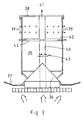
- Fig. 1 shows a combustion device of the invention installed in a fireplace.
- the fireplace comprises a grate 1; a fire chamber 2; a fire door 3 of the fire chamber; a rear wall 4 of the fire chamber; an ash bin 5; and an ash box door 6.
- the combustion device comprises a box made of a metal sheet and having a rear wall 7 supported against the rear wall 4 of the fire chamber; a front wall 8 obliquely inclined forward and upward toward the fire door 3; a lid 9; side walls (in the plane of the drawing); as well as a bottom 10 directed obliquely downward and forward from the rear wall 7, which together form a combustible matter compartment 11 tapering downward toward the grate 1.
- a flow port 12 is formed, from which the granular combustible matter is allowed to flow down by gravity into an additional grate 13, disposed on top of the grate 1 as a horizontal extension to the bottom 10.
- the front wall 8 is a non-insulated metal sheet which functions as a heat transfer element 14, which conducts heat from the combustion space 2 into the combustible matter compartment 11.
- the front wall is provided with direction elements 15 i.e. holes that conduct the gases produced in the combustible matter compartment into the combustion space.
- Combustion air 16 is fed into the combustion process via the ash box door 6 and grate 1 as follows. A part of the combustion air enters through the grate 1 the additional grate 13, whereupon the combustible matter disposed on top of it burns.
- the combustible matter compartment 11 is flanked by additional ducts 17, which convey a part of the combustion air that has entered through the grate 1 into a space above the grate 1 near to the holes 15.
- the combustible matter compartment 11 is also flanked by secondary combustion air ducts 18, which convey a part of the combustion air over top of the combustible matter compartment.
- the bottom 10 includes cleaning combustion air ducts 19 i.e. holes that direct the combustion air directly into the combustible matter compartment 11 relatively close to the flow port 12.
- the combustion device shown in Fig. 1 functions as follows. Once the combustible matter compartment has been filled with pellets or some other granular combustible matter, a part of it flows onto the additional grate 13. Therein, it can be lit e.g. with lighter fluid or some other inflammation material. Besides the combustion space 2, the combustion process starts to heat the front wall 8 of the combustible matter compartment 11, i.e. the heat transfer element 14, whereby also the combustible matter in the combustible matter compartment 11 starts to heat up and gasify.
- the gases are released into the combustion space via the direction elements 15 and burn by means of the additional combustion air provided by the additional ducts 17 thereby ensuring complete burning of the combustion gases rising from the grate 1 and the additional grate 13.
- the hot gases rise up above the combustible matter compartment, into which more combustion air is fed by the secondary combustion air ducts 18; and in this manner, in the upper part of the fireplace, the additional oxygen that has been fed over the top of the combustible matter compartment is used to ensure a clean and complete combustion process.
- the cleaning combustion air ducts 19 open and direct the combustion air directly into the combustible matter compartment 11 which is becoming empty. In this manner, the gases gasifying from the combustible matter burn whilst in the combustible matter compartment, which at the end of the combustion process ensures that the combustible matter compartment is kept clean with no impurities remaining therein.
- Fig. 2 shows another embodiment of the invention with alternative structural solutions shown with a broken line.
- the principled functioning of the device is similar per se to that shown in Fig. 1.
- placed within the fire chamber of the fireplace is a whole consisting of a bottom 20 and an additional grate 21, as well as of a front wall 22 and a lid 23 of the combustible matter compartment that are supported on these as well as on the rear wall of the fireplace.
- Even the additional grate 21 can be omitted if the actual grate is so small-holed that the granular combustible matter is not allowed to flow through it unburned.
- the combustion air 24 of the grate burning is fed from below the grate 25, from the ash bin.
- the fire door 26 of the fireplace, or the sides thereof, are provided with additional ducts 27, conveying the combustion air over the top of the additional grate 21, near to the holes 28 in the front wall 22.
- the fire door 26 of the fire chamber, or the sides or top part thereof are provided with secondary combustion air ducts 29, directing the combustion air over the top of the combustible matter compartment.
- the cleaning combustion air ducts 30, i.e. the holes in the rear wall of the fireplace direct the combustion air directly into the lower part of the combustible matter compartment and these open when the level of combustible matter has dropped below the level of these.
- Fig. 2 shows tubular direction elements 31 depicted with a broken line, these extending from the combustible matter compartment via the flow port 32 over the top of the additional grate 21.
- holes 28 these can also direct the gases gasifying from the combustible matter into a desired place in the combustion space 33.
- one or more tubular combustion ducts 34 are shown, starting from the vicinity of the additional grate from the top side thereof.
- the hot combustion gases are directed into the upper part of the combustion space by the combustion duct provided in the combustible matter compartment. In this manner, heat is transferred from the gases into the combustible matter to gasify it.
- the combustion ducts 34 can be provided with an adjustment enabling one to regulate the gasification of the combustible matter. It is even possible that the front wall is insulated, whereby the gasification heat is conveyed into the combustible matter using the combustion ducts.
- the combustible matter compartment is a cylindrical tank to be placed in the middle of the fire chamber of the fireplace, on top of the grate. While the structure of this embodiment is different, the functioning of its different parts is similar to that shown in the embodiments of Figs. 1 and 2.
- a direction cone 36 At the bottom of the combustible matter compartment 35 there is a direction cone 36, distributing the combustible matter uniformly onto the surrounding angular additional grate 37.
- the tank is covered by a lid 38, and the tank can be filled by opening the lid.
- the cylindrical jacket of the tank acts as a heat transfer element conducting a part of the heat being generated in the combustion process that takes place on top of the additional grate into the combustible matter compartment to gasify the combustible matter.
- the direction elements i.e. holes 39 in the jacket direct the burning gases into the combustion space on top of the additional grate.
- all the necessary additional combustion air can be obtained through the grate by conducting it into the desired places via a central duct 40 provided in the combustible matter compartment.
- the central duct 40 conducts a part of the combustion air over the top of the combustible matter compartment to form secondary combustion air 41; a part of the combustion air to be used in the combustion of the gases flowing through the holes 39 along the additional ducts 42; and a part of the combustion air into the combustible matter compartment via the cleaning combustion air ducts i.e. holes 43 disposed in the lower part of the central duct.
- the flow of combustible matter that takes place via the flow port by gravity can be regulated by elevating or lowering the entire tank with respect to the conical level, in which case the flow port is either reduced or increased.
- the regulation can also be effected by elevating or lowering the conical level 36 or by adjusting the steepness of the conical level. While Fig. 3 shows a round cylindrical structure, it is obvious that the same inventive structure also works for structures having e.g. an elliptical or angular horizontal cross section.
- the additional grate does not need to enclose the entire combustible matter compartment, but it can only extend through a part of the circumference of the combustible matter compartment, such as the opposite sides of the space, a half of the surrounding circumference, etc. In that case, naturally, the conical or oblique surface is so directed that it uniformly divides the combustible matter through the length of the grate to be used.
- Figs. 4 and 5 show one embodiment of the invention in greater detail, the embodiment corresponding to that shown in Fig. 1 with respect to its structure and functioning; that is, it has a substantially solid metal tank 44 which forms the combustible matter compartment.
- the upper part thereof is provided with an openable lid 45 and the lower part is provided with a flow port 46, from which the combustible matter is allowed to flow by gravity into the additional grate 47.
- the additional grate 47 stays in place in the fire chamber while the combustible matter compartment is partly turned out of the fire chamber so that the lid 45 can be opened without, however, removing or detaching the tank out of place.
- a turning handle 48 allowing one to easily turn the tank into a filling position and back into an operation position. It is even possible that the turning handle is removable so that it is mounted in place only when using it and otherwise kept out of the fire chamber. In this manner, it is kept clean and it is never hot when using it.
- the path of motion of the turning handle can also be provided with an adjustment by which the size of the flow port is adjusted.
Abstract
Description
- The invention relates to a method defined in the preamble of claim 1 and to a device defined in the preamble of
claim 10 for burning granular combustible matter in fireplaces. - It is known in prior-art to burn granular combustible matter, such as pellets, grain or suitable chips, in various automatic feed combustion boilers, where a screw or the like is used to feed combustible matter to be burned. Heaters such as these require, however, continuous electricity, so they are as vulnerable as oil heating and electric heating, in contrast to conventional fireplaces using solid combustible matter.
- For burning pellets in fireplaces, various pellet baskets have been developed, which are partly open from the top and the sides, and filled with pellets are placed within the fire chamber of a fireplace. In the basket, the pellets burn from the top and receive the combustion air from the sides.
- Known from patent
US6397833 is also a natural draft, gravity feed pellet stove. - The basis for the prior-art combustion devices of pellets has been long and uniform burning and long and uniform heat release along with it. In that case, however, the combustion temperature and the combustion itself are not necessarily optimal. In the combustion, impurities are produced that could be avoided with a better combustion process. In particular, prior-art combustion devices are not suited for, or are not worth using in heat-storing fireplaces because they could store heat better if the combustion process was hotter and faster.
- The basis for the invention has been the combustion of granular combustible matter, such as pellets, grain or suitable chips, as completely and cleanly as possible.
- One further objective has been to disclose a method and device that are independent of external energy; that is they are fully operable also in non-electric conditions.
- One specific objective of the invention is to disclose a method and device that enable easy and simple heating which releases heat uniformly and over a long period of time into the room to be heated.
- One further objective of the invention is to enable the burning of granular combustible matter in heat-storing fireplaces, specifically in soapstone fireplaces, as cleanly and efficiently as possible.
- It is also an objective of the invention to disclose a fireplace in which it is possible to burn in turns or even simultaneously both wood and granular combustible matter.
- The method for burning granular combustible matter is characterized by what is presented in claim 1.
- In the combustion method of the invention for burning granular combustible matter it is possible to use both heat-storing and stove-type fireplaces different in structure. However, the invention works better for heat-storing fireplaces, so preferably, the fire chamber of the fireplace as well as the flow ducts of hot smoke gases after it are made of soapstone with a good heat-storing capacity, although also other materials with a good heat-storing capacity can be used. The fireplace comprises a fire chamber with exhaust ducts of combustion gases; a grate, into which combustion air is conducted; as well as in the fire chamber, a combustible matter compartment tapering downward toward the grate and dividing the fire chamber into a combustible matter compartment and combustion space and having in the lower part thereof a flow port, from which the combustible matter flows onto the grate by gravity and burns therein. According to the invention, the combustible matter is gasified in the combustible matter compartment and the burning gases thus obtained are conducted from the combustible matter compartment into the combustion space, where they are burned. In this manner, the invention shows efficient two-phase burning as the granular combustible matter is burning on top of the grate in the first phase and the yet unburned gases rising upward from the grate and the gases flowing from the combustible matter compartment are mixed and burn in the second phase upper in the combustion space in the vicinity of the front wall of the combustible matter compartment.
- Preferably, into the burning process of this second phase, more combustion air is conducted, which can happen by directing a part of the combustion air that has flown through the grate past or through the combustible matter compartment past the first combustion phase. The combustion air of the second phase can also be directed into the fireplace via the furnace door or from the vicinity of the furnace door.
- In a preferred embodiment of the invention, the cleanliness of the burning process can be further enhanced in the third phase by conducting combustion air also into a space above the combustible matter compartment, into the beginning of the exhaust duct, into a so-called upper combustion space, where additional oxygen in the hottest part of the fireplace guarantees complete and clean burning.
- In the method of the invention, the combustible matter compartment preferably is so dimensioned that with a single filling of combustible matter the entire heat-storing capacity of the fireplace can be reserved. In this manner, one does not need to handle a hot stove, but as one runs out of combustible matter and the fire is out, all one has to do is to close the dampers.
- In order to also make the final phase of burning as efficient and clean a process as possible, it is preferable to use in the invention a fourth combustion phase. In that case, as the amount of combustible matter in the combustible matter compartment drops below a given limit, combustion air is fed into the combustible matter compartment, whereby the combustion gases produced in the combustible matter compartment catch fire whilst in the combustible matter compartment. They burn partly or wholly whilst in the combustible matter compartment, which is to ensure that no pitch, possibly produced as a result of combustion with low combustion air, is developed in the combustible matter compartment; and it can be kept clean for the next combustion.
- When using a fireplace that stores heat well, such as a soapstone fireplace, the combustion need not be restrained, but granular combustible matter can be burned quickly and efficiently in hot conditions, which ensures cleanliness of the combustion and good efficiency of heat-storage. In the invention, the combustion can be regulated by regulating the flow of combustible matter that takes place by gravity through the flow port onto the grate. It happens by simply changing the size of the flow port or by adjusting the flow port toward the inclination of the bottom of the tapering combustible matter compartment.
- It is also possible that the combustion is regulated by regulating the accumulation of combustible matter in the combustible matter compartment. This adjustment is best made by changing the amount of heat to be conducted from the combustion space into the combustible matter compartment. The combustion can also be regulated by regulating the flow of combustion air into the combustible matter compartment, as well as by regulating the access of gasified agents from the combustible matter compartment into the combustion space by changing the size or number of the flow ports.
- The combustion device of the invention for burning granular combustible matter is characterized by what is presented in
claim 10. - The combustion device of the invention is primarily designed to be used in massive fireplaces that store heat well, such in soapstone fireplaces, although it is suited to be used also in other types of fireplaces, even in stoves. Thus, preferably, the fire chamber of the fireplace, as well as the flow ducts of hot smoke gases after it are made of soapstone that stores heat well, although also other materials can be used.
- The fireplace of the invention comprises a fire chamber with exhaust ducts of combustion gases; a grate, into which combustion air is conducted; as well as in the fire chamber, a combustible matter compartment tapering downward toward the grate and dividing the fire chamber into a combustible matter compartment and combustion space and having in the lower part thereof a flow port, from which the combustible matter flows onto the grate by gravity. According to the invention, the combustion device comprises a heat transfer element for conducting the heat contained in the combustion space partly into the combustible matter compartment for gasifying the combustible matter, as well as direction elements for directing the combustion gases that have been gasified in the combustible matter compartment from the combustible matter compartment into the combustion space to be burned. In this manner, the gasification of the combustible matter begins partly already in the combustible matter compartment, due to which the entire combustion process can be made a clean and fast process to be performed at a higher temperature.
- Preferably, the combustion device has suitable additional ducts, by which fresh combustion air is conducted into a space above the grate into the combustion space of the fire chamber for cleanly and completely burning the gasified combustion gases to be conducted from the combustible matter compartment. The additional ducts can conduct combustion air from below the grate, the ash bin, for example, past the combustible matter compartment into the combustion process. The additional ducts can also be disposed in the fire door of the fire chamber or in some other suitable place.
- Transfer of a sufficient amount of heat from the combustion space into the combustible matter compartment for implementing suitable gasification of the combustible matter can be performed in many different ways. In the simplest way it is done with a heat transfer element consisting of a metallic wall of the combustible matter compartment or a part of the wall. In this manner, the heat of the fire chamber warms the wall, which conducts the heat directly into the combustible matter compartment disposed on the other side thereof. The heat transfer can be regulated by covering the wall with a partly heat-isolating material, in which case only a part of the wall acts as a heat transfer element. Various movable insulation elements are also possible, in case there is a wish to make the adjustment operable in conjunction with use.
- Similarly, it is possible that the heat transfer element consists of one or more tubular combustion ducts provided through the combustible matter compartment, along which combustion ducts the hot combustion gases produced in the combustion in the grate flow from the fire chamber either into the upper part of the fire chamber or above the combustible matter compartment. In this embodiment, the adjustment is simple to implement by arranging in the combustion duct a suitable regulator or shutter of gas flow.
- In a preferred embodiment of the invention, the direction elements, by which the combustion gases are conducted from the combustible matter compartment into the combustion space, consist of holes in the wall of the combustible matter compartment. The shape, number and location of the holes can vary greatly in different embodiments. The holes can form in the wall, especially in the front wall visible from the fire door of the fireplace, various patterns, symbols or similar, which are seen through the glass fire door of the fireplace as the burning gas flows are released through the holes into the combustion space, or when the gases are burning in the combustible matter compartment. The holes can also be provided with a regulator by means of which they can be closed either partly or wholly, if desired. A part of the holes can also be disposed in the lid of the combustible matter compartment thereby directing the combustion gases more upwards; or being disposed substantially parallel to the lid, a part of the front wall of the combustible matter compartment can be disposed on top of the combustible matter compartment and provided with holes, in which case a solid or a perforated lid only covers the rear part of the upper part of the combustible matter compartment.
- In another embodiment, the direction elements consist of flow tubes conveyed from the combustible matter compartment through the wall or flow port of the combustible matter compartment into the combustion space. The flow tubes can start from different areas of the combustible matter compartment, but mainly from the upper part thereof. Similarly, by means of separate flow tubes, the burning hot gases can be easily conducted into the combustion space, the best possible place in terms of clean and complete burning. This place can be even adjustable according to the combustion efficiency to be used each time.
- In one embodiment of the invention, the combustion device comprises secondary combustion air ducts, arranged to conduct combustion air into the combustion space, above the combustible matter compartment, i.e. into a so-called upper combustion space. The additional oxygen, which ensures complete and clean burning, can be conducted into the hottest part of the fireplace e.g. through the grate within the fireplace and upward along the sides of the combustible matter compartment. It is also possible to use separate air ducts starting from beneath the grate, from the vicinity of the fire door of the fireplace or from a suitable point from outside the fireplace. These can be provided at the edges of the combustible matter compartment, behind it or even through the combustible matter compartment.
- In one embodiment of the invention, the combustion device comprises cleaning combustion air ducts, arranged to open out into the combustible matter compartment. These can be provided with suitable shutter elements that keep the ducts closed in case of a full combustible matter tank, but as the amount of combustible matter drops below a given limit, open them letting combustion air inside the combustible matter compartment. Preferably, however, the cleaning combustion air ducts are so dimensioned and disposed to open into the combustible matter compartment that the granular combustible matter itself keeps the ducts closed sufficiently tightly when there is a given amount of combustible matter. When the level of combustible matter in the combustible matter compartment then drops, the ends of the ducts open in a given phase and oxygen-rich air is allowed to flow into the combustible matter compartment, which oxygen-rich air sets the gases in the space on fire. This fourth combustion phase considerably raises the temperature in the combustible matter compartment, whereby possible production of pitch in the space is prevented and the pitch possibly produced in the space in the gasification phase is burned off. After use, the device is always clean, safe and ready for a new filling of combustible matter and heating.
- In the combustion device of the invention, in addition to the front wall, the combustible matter compartment can consist at least partly of structures of the fire chamber of the fireplace, i.e. e.g. of the rear and side walls thereof. In this manner, one only needs to install in the fireplace an oblique part of the rear wall, which directs the combustible matter into the grate; a front wall which divides the fire chamber into the combustible matter compartment and the combustion space; and a lid by means of which the combustible matter compartment is covered substantially gas tightly.
- In another embodiment of the invention, the combustible matter compartment consists of a separate fireproof box comprising a front wall, a rear wall, a side wall and a lid and having in the lower part thereof a flow port from which the combustible matter flows into the grate. The separate box preferably is detached so that it can be freely put into the fire chamber and taken out of it according to need. In this manner, the same fireplace can be heated alternatively both with wood and granular combustible matter.
- The shape of the separate fireproof box can vary relatively freely. The box can solely direct the combustible matter into the grate only to its one edge, in which case the combustible matter compartment can be supported on the edges of the fire chamber. The combustible matter can also flow from the combustible matter compartment into two opposite directions, for example, towards the edges of the fire chamber. Possible is also an embodiment where the combustible matter compartment is formed by a container to be placed on top of the grate, e.g. a container shaped like a cylinder, which in the lower part thereof is enclosed by the grate so that the combustible matter is allowed to flow onto the grate from every side of the container. In this manner, burning flames surround the combustible matter compartment from every side.
- Usually, in slot grates of fireplaces, the slots are so big that pellets and other granular combustible matter would flow directly into the ash bin. Due to this, preferably, arranged below the flow port of the combustible matter compartment is an additional grate disposed on top of the grate of the fire chamber, where the size of the air slots is of the order of a couple of millimeters so that the granular combustible matter is not allowed to flow through them. In this manner, the granular combustible matter is burning on the additional grate obtaining the combustion air through the grate and the additional grate as the minor amount of ash being produced is flowing through the grates into the ash bin.
- In one embodiment of the invention, the separate box-like combustible matter compartment is pivotally connected to the bottom of a fire chamber, such as a grate. As its lid is provided with an openable hatch, the combustible matter compartment can be filled with fresh combustible matter simply by turning it outwards from the fire chamber so that the filling hole covered by the hatch will become visible. In this manner, the combustible matter compartment need no be lifted from the fire chamber, which makes the filling of combustible matter a simple, clean and quick process. Combustible matter compartments of other shapes can also be preferably designed so that they can be filled without removing them from the fire chamber.
- The combustion method and combustion device of the invention have considerable advantages compared to the prior art:
- The uniform four-phase combustion process of the invention achieves uniform burning and highly small emissions.
- It suits all fireplaces which are different in structure and functioning.
- The invention specifically improves the uses of granular combustible matter in heat-storing fireplaces.
- In the same fireplace it is possible to burn both wood and granular combustible matter even by letting the inventive combustion device be in the fire chamber all the time. In this manner, the use is simple and clean irrespective of the combustible matter to be used.
- With correct dimensioning, a single filling suffices to fully reserve the heat-storage capacity of the fireplace, so one does not need to fill a hot fireplace with combustible matter, which is an important safety factor.
- The combustion device of the invention can be easily lit like a conventional fireplace, and the inflammation is so quick that the problem of humidity condensation, caused by slow inflammation and typical of prior-art pellet stoves is avoided.
- The burning in accordance with the invention necessitates no regulation during the burning.
- The combustion device of the invention can be easily installed into existing fireplaces.
- In the following section, the invention will be described in detail referring to the attached drawings, in which
- Fig. 1 is a schematic side view illustrating one combustion device of the invention;
- Fig. 2 is a schematic side view illustrating another combustion device of the invention; and
- Fig. 3 is schematic sectional view illustrating a third combustion device of the invention;
- Fig. 4 illustrates a fourth combustion device of the invention; and
- Fig. 5 is a side view of the combustion device shown in Fig. 5.
- Fig. 1 shows a combustion device of the invention installed in a fireplace. The fireplace comprises a grate 1; a
fire chamber 2; afire door 3 of the fire chamber; arear wall 4 of the fire chamber; anash bin 5; and anash box door 6. The combustion device comprises a box made of a metal sheet and having arear wall 7 supported against therear wall 4 of the fire chamber; afront wall 8 obliquely inclined forward and upward toward thefire door 3; alid 9; side walls (in the plane of the drawing); as well as a bottom 10 directed obliquely downward and forward from therear wall 7, which together form acombustible matter compartment 11 tapering downward toward the grate 1. - Between the bottom 10 and the
front wall 8, aflow port 12 is formed, from which the granular combustible matter is allowed to flow down by gravity into anadditional grate 13, disposed on top of the grate 1 as a horizontal extension to the bottom 10. Thefront wall 8 is a non-insulated metal sheet which functions as aheat transfer element 14, which conducts heat from thecombustion space 2 into thecombustible matter compartment 11. In addition, the front wall is provided withdirection elements 15 i.e. holes that conduct the gases produced in the combustible matter compartment into the combustion space. -
Combustion air 16 is fed into the combustion process via theash box door 6 and grate 1 as follows. A part of the combustion air enters through the grate 1 theadditional grate 13, whereupon the combustible matter disposed on top of it burns. Thecombustible matter compartment 11 is flanked byadditional ducts 17, which convey a part of the combustion air that has entered through the grate 1 into a space above the grate 1 near to theholes 15. Thecombustible matter compartment 11 is also flanked by secondarycombustion air ducts 18, which convey a part of the combustion air over top of the combustible matter compartment. Further, the bottom 10 includes cleaningcombustion air ducts 19 i.e. holes that direct the combustion air directly into thecombustible matter compartment 11 relatively close to theflow port 12. - The combustion device shown in Fig. 1 functions as follows. Once the combustible matter compartment has been filled with pellets or some other granular combustible matter, a part of it flows onto the
additional grate 13. Therein, it can be lit e.g. with lighter fluid or some other inflammation material. Besides thecombustion space 2, the combustion process starts to heat thefront wall 8 of thecombustible matter compartment 11, i.e. theheat transfer element 14, whereby also the combustible matter in thecombustible matter compartment 11 starts to heat up and gasify. The gases are released into the combustion space via thedirection elements 15 and burn by means of the additional combustion air provided by theadditional ducts 17 thereby ensuring complete burning of the combustion gases rising from the grate 1 and theadditional grate 13. The hot gases rise up above the combustible matter compartment, into which more combustion air is fed by the secondarycombustion air ducts 18; and in this manner, in the upper part of the fireplace, the additional oxygen that has been fed over the top of the combustible matter compartment is used to ensure a clean and complete combustion process. Further, at the final step of burning, when one is running out of combustible matter in thecombustible matter compartment 11, the cleaningcombustion air ducts 19 open and direct the combustion air directly into thecombustible matter compartment 11 which is becoming empty. In this manner, the gases gasifying from the combustible matter burn whilst in the combustible matter compartment, which at the end of the combustion process ensures that the combustible matter compartment is kept clean with no impurities remaining therein. - Fig. 2 shows another embodiment of the invention with alternative structural solutions shown with a broken line. The principled functioning of the device is similar per se to that shown in Fig. 1. In Fig. 2, placed within the fire chamber of the fireplace is a whole consisting of a bottom 20 and an
additional grate 21, as well as of afront wall 22 and alid 23 of the combustible matter compartment that are supported on these as well as on the rear wall of the fireplace. Even theadditional grate 21 can be omitted if the actual grate is so small-holed that the granular combustible matter is not allowed to flow through it unburned. Thecombustion air 24 of the grate burning is fed from below thegrate 25, from the ash bin. Thefire door 26 of the fireplace, or the sides thereof, are provided withadditional ducts 27, conveying the combustion air over the top of theadditional grate 21, near to theholes 28 in thefront wall 22. Similarly, thefire door 26 of the fire chamber, or the sides or top part thereof, are provided with secondarycombustion air ducts 29, directing the combustion air over the top of the combustible matter compartment. In addition, the cleaningcombustion air ducts 30, i.e. the holes in the rear wall of the fireplace, direct the combustion air directly into the lower part of the combustible matter compartment and these open when the level of combustible matter has dropped below the level of these. - In an alternative embodiment, Fig. 2 shows
tubular direction elements 31 depicted with a broken line, these extending from the combustible matter compartment via theflow port 32 over the top of theadditional grate 21. Instead ofholes 28, these can also direct the gases gasifying from the combustible matter into a desired place in thecombustion space 33. - As an alternative structure instead of the
heat transfer element 22 i.e. the front wall or in addition to that, one or moretubular combustion ducts 34 are shown, starting from the vicinity of the additional grate from the top side thereof. The hot combustion gases are directed into the upper part of the combustion space by the combustion duct provided in the combustible matter compartment. In this manner, heat is transferred from the gases into the combustible matter to gasify it. If necessary, thecombustion ducts 34 can be provided with an adjustment enabling one to regulate the gasification of the combustible matter. It is even possible that the front wall is insulated, whereby the gasification heat is conveyed into the combustible matter using the combustion ducts. - In the embodiment of Fig. 3, the combustible matter compartment is a cylindrical tank to be placed in the middle of the fire chamber of the fireplace, on top of the grate. While the structure of this embodiment is different, the functioning of its different parts is similar to that shown in the embodiments of Figs. 1 and 2. At the bottom of the
combustible matter compartment 35 there is adirection cone 36, distributing the combustible matter uniformly onto the surrounding angularadditional grate 37. The tank is covered by alid 38, and the tank can be filled by opening the lid. The cylindrical jacket of the tank acts as a heat transfer element conducting a part of the heat being generated in the combustion process that takes place on top of the additional grate into the combustible matter compartment to gasify the combustible matter. The direction elements i.e. holes 39 in the jacket direct the burning gases into the combustion space on top of the additional grate. - In this embodiment, all the necessary additional combustion air can be obtained through the grate by conducting it into the desired places via a
central duct 40 provided in the combustible matter compartment. Thecentral duct 40 conducts a part of the combustion air over the top of the combustible matter compartment to formsecondary combustion air 41; a part of the combustion air to be used in the combustion of the gases flowing through theholes 39 along theadditional ducts 42; and a part of the combustion air into the combustible matter compartment via the cleaning combustion air ducts i.e. holes 43 disposed in the lower part of the central duct. - The flow of combustible matter that takes place via the flow port by gravity can be regulated by elevating or lowering the entire tank with respect to the conical level, in which case the flow port is either reduced or increased. The regulation can also be effected by elevating or lowering the
conical level 36 or by adjusting the steepness of the conical level. While Fig. 3 shows a round cylindrical structure, it is obvious that the same inventive structure also works for structures having e.g. an elliptical or angular horizontal cross section. In the same manner, the additional grate does not need to enclose the entire combustible matter compartment, but it can only extend through a part of the circumference of the combustible matter compartment, such as the opposite sides of the space, a half of the surrounding circumference, etc. In that case, naturally, the conical or oblique surface is so directed that it uniformly divides the combustible matter through the length of the grate to be used. - Figs. 4 and 5 show one embodiment of the invention in greater detail, the embodiment corresponding to that shown in Fig. 1 with respect to its structure and functioning; that is, it has a substantially
solid metal tank 44 which forms the combustible matter compartment. The upper part thereof is provided with anopenable lid 45 and the lower part is provided with aflow port 46, from which the combustible matter is allowed to flow by gravity into theadditional grate 47. In this embodiment, there is a turningpivot support 49 between the additional grate and the combustible matter compartment. Thus, theadditional grate 47 stays in place in the fire chamber while the combustible matter compartment is partly turned out of the fire chamber so that thelid 45 can be opened without, however, removing or detaching the tank out of place. In addition, in this embodiment, there is a turninghandle 48 allowing one to easily turn the tank into a filling position and back into an operation position. It is even possible that the turning handle is removable so that it is mounted in place only when using it and otherwise kept out of the fire chamber. In this manner, it is kept clean and it is never hot when using it. The path of motion of the turning handle can also be provided with an adjustment by which the size of the flow port is adjusted. - The invention is not limited merely to the examples referred to above, but many modifications are possible within the scope of the inventive idea defined by the claims.
Claims (27)
- A combustion method for burning granular combustible matter in a fireplace comprising a fire chamber with exhaust ducts of combustion gases; a grate (1), into which combustion air is conducted; as well as in the fire chamber, a combustible matter compartment (11) tapering downward toward the grate and dividing the fire chamber into a combustible matter compartment and a combustion space (2) and having in the lower part thereof a flow port (12), from which the combustible matter flows by gravity onto the grate (1) burning therein, characterized in that the combustible matter is gasified in the combustible matter compartment (11) and the burning gases thus obtained are conducted from the combustible matter compartment into the combustion space (2), where they are burned.
- The method as defined in claim 1, characterized in that combustion air is conducted over the top of the burning combustible matter disposed on the grate.
- The method as defined in claim 1 or 2, characterized in that combustion air is also conducted over the top of the combustible matter compartment into the beginning of the exhaust duct to ensure complete, clean burning.
- The method as defined in any one of claims 1 to 3, characterized in that a part of the burning gases is burned in the combustible matter compartment.
- The method as defined in any of claims 1 to 4, characterized in that as the amount of combustible matter in the combustible matter compartment (11) drops below a given limit, combustion air is fed into the combustible matter compartment, whereby the combustion gases generated in the combustible matter compartment are burned partly in the combustible matter compartment and partly in the combustion space.
- The method as defined in any one of claims 1 to 5, characterized in that the combustion process is regulated by regulating the flow of combustible matter via the flow port (12) onto the grate.
- The method as defined in any one of claims 1 to 6, characterized in that the combustion process is regulated by regulating the accumulation of combustible matter in the combustible matter compartment (11)
- The method as defined in any one of claims 1 to 7, characterized in that in the method, pellets, grain or suitable chips are burned.
- The method as defined in any one of claims 1 to 8, characterized in that the combustion is performed in a massive fireplace that stores heat well, such in a soapstone fireplace.
- A combustion device for burning granular combustible matter in a fireplace comprising a fire chamber with exhaust ducts of combustion gases; a grate (1), into which combustion air is conducted; as well as in the fire chamber, a combustible matter compartment (11) tapering downward toward the grate and dividing the fire chamber into a combustible matter compartment and a combustion space (2) and having in the lower part thereof a flow port (12), from which the combustible matter flows by gravity onto the grate, characterized in that the combustion device comprises a heat transfer element (14) for directing the heat contained in the combustion space (2) partly into the combustible matter compartment (11) for gasifying the combustible matter; as well as direction elements (15) for directing the combustion gases gasified in the combustible matter compartment from the combustible matter compartment into the combustion space to be burned.
- The combustion device as defined in claim 10, characterized in that the combustion device comprises additional ducts (17) by means of which fresh combustion air is conducted into the combustion space (2) above the grate (1) for burning the gasified combustion gases to be conducted from the combustible matter compartment.
- The combustion device as defined in claim 10 or 11, characterized in that the heat transfer element (14) consists of a metallic wall of the combustible matter compartment, or of a part thereof.
- The combustion device as defined in claim 10 or 11, characterized in that the heat transfer element consists of one or more tubular combustion ducts (34) provided through the combustible matter compartment.
- The combustion device as defined in any one of claims 10 to 13, characterized in that the direction elements (15) are holes in the wall of the combustible matter compartment.
- The combustion device as defined in any one claims 10 to 13, characterized in that the direction elements are flow tubes (31) conveyed from the combustible matter compartment into the combustion space through the wall or flow port of the combustible matter compartment.
- The combustion device as defined in claim 14 or 15, characterized in that the direction elements are provided with a regulation by means of which the flow of hot combustion gases can be regulated or completely shut.
- The combustion device as defined in any one of claims 10 to 16, characterized in that the combustion device comprises secondary combustion air ducts (18), arranged to conduct combustion air into the combustion space above the combustible matter compartment (11).
- The combustion device as defined in any one of claims 10 to 17, characterized in that the combustion device comprises cleaning combustion air ducts (19), arranged to open into the combustible matter compartment (11) as the amount of combustible matter drops below a given limit, and to conduct combustion air into the combustible matter compartment.
- The combustion device as defined in any one of claims 10 to 18, characterized in that in addition to the front wall (22), the combustible matter compartment consists at least partly of the rear and side walls of the fire chamber of the fireplace.
- The combustion device as defined in any one of claims 10 to 18, characterized in that the combustible matter compartment (11) is formed by a separate box comprising a front wall (8), a rear wall (7), side walls and a lid (9) and having a flow port (12) in the lower part thereof.
- The combustion device as defined in claim 20, characterized in that in the lower part of the flow port (12) of the combustible matter compartment (11) there is an additional grate (13) disposed on top of the grate (1) of the fire chamber, in which additional grate the granular combustible matter burns.
- The combustion device as defined in claim 20 or 21, characterized in that the combustible matter compartment (44) is pivotally connected to the bottom of the fire chamber, such as a grate (47), so that its upper part can be partially turned out of the fire chamber to fill the combustible matter compartment.
- The combustion device as defined in claim 20 or 21, characterized in that the combustible matter compartment (35) is a tank supported on top of the grate and enclosed by the combustion space in the horizontal direction.
- The combustion device as defined in claim 23, characterized in that the additional grate (37) is an angular structure with the combustible matter compartment disposed in the middle.
- The combustion device as defined in claim 23, characterized in that a central duct (40) is provided through the combustible matter compartment (35), which central duct, starting from above the grate, directs the combustion air that has flown through the grate over the top of the combustible matter compartment to form secondary combustion air, over the top of the burning combustible matter into the combustion space and/or the combustible matter compartment.
- The combustion device as defined in claim 23, characterized in that the bottom of the combustible matter compartment is provided with a direction cone (36), which distributes the combustible matter uniformly partly or wholly onto the grate that encloses the combustible matter compartment.
- The combustion device as defined in any one of claims 23 to 26, characterized in that the flow of combustible matter through the flow port disposed in the lower part of the combustible matter compartment (35) is regulated by regulating the height of the jacket of the combustible matter compartment with respect to the additional grate (37), by regulating the height of the direction cone and/or by regulating the inclination of the direction cone.
Applications Claiming Priority (1)
| Application Number | Priority Date | Filing Date | Title |
|---|---|---|---|
| FI20060094A FI118823B (en) | 2006-01-31 | 2006-01-31 | Combustion process and combustion device |
Publications (2)
| Publication Number | Publication Date |
|---|---|
| EP1826483A2 true EP1826483A2 (en) | 2007-08-29 |
| EP1826483A3 EP1826483A3 (en) | 2013-09-04 |
Family
ID=35883903
Family Applications (1)
| Application Number | Title | Priority Date | Filing Date |
|---|---|---|---|
| EP06396022.3A Withdrawn EP1826483A3 (en) | 2006-01-31 | 2006-12-20 | Combustion method and combustion device |
Country Status (2)
| Country | Link |
|---|---|
| EP (1) | EP1826483A3 (en) |
| FI (1) | FI118823B (en) |
Cited By (7)
| Publication number | Priority date | Publication date | Assignee | Title |
|---|---|---|---|---|
| FR2973481A1 (en) * | 2011-03-30 | 2012-10-05 | Oliger France | Feeding device for feeding wood pellets by gravity to burner in hearth of heating installation, has movable unit distributing pellets in device for supply to burner, and low power direct current motor imparting motion to movable unit |
| EP2775201A2 (en) | 2013-03-08 | 2014-09-10 | Thomas Blank | Heating device, storage insert for a heating device and method for operating a heating device |
| WO2015131825A1 (en) * | 2014-03-05 | 2015-09-11 | 车战斌 | Combustion apparatus for solid fuel |
| WO2015144032A1 (en) * | 2014-03-25 | 2015-10-01 | 车战斌 | Solid fuel combustion device |
| WO2015149637A1 (en) * | 2014-04-04 | 2015-10-08 | 车战斌 | Combustion device for solid fuels |
| WO2016119195A1 (en) * | 2015-01-30 | 2016-08-04 | 车战斌 | Combustion equipment for solid fuel |
| WO2016119214A1 (en) * | 2015-01-30 | 2016-08-04 | 车战斌 | Combustion equipment for solid fuel |
Citations (3)
| Publication number | Priority date | Publication date | Assignee | Title |
|---|---|---|---|---|
| DE396954C (en) * | 1923-03-21 | 1924-06-23 | Uhlmann Johannes | Sectional boiler with lower combustion for raw lignite combustion |
| FR613067A (en) * | 1926-03-20 | 1926-11-08 | Solid fuel furnace hearth | |
| DE464185C (en) * | 1928-08-09 | Franz Hof | Grate furnace with built-in drying and smoldering shaft |
-
2006
- 2006-01-31 FI FI20060094A patent/FI118823B/en active
- 2006-12-20 EP EP06396022.3A patent/EP1826483A3/en not_active Withdrawn
Patent Citations (3)
| Publication number | Priority date | Publication date | Assignee | Title |
|---|---|---|---|---|
| DE464185C (en) * | 1928-08-09 | Franz Hof | Grate furnace with built-in drying and smoldering shaft | |
| DE396954C (en) * | 1923-03-21 | 1924-06-23 | Uhlmann Johannes | Sectional boiler with lower combustion for raw lignite combustion |
| FR613067A (en) * | 1926-03-20 | 1926-11-08 | Solid fuel furnace hearth |
Cited By (9)
| Publication number | Priority date | Publication date | Assignee | Title |
|---|---|---|---|---|
| FR2973481A1 (en) * | 2011-03-30 | 2012-10-05 | Oliger France | Feeding device for feeding wood pellets by gravity to burner in hearth of heating installation, has movable unit distributing pellets in device for supply to burner, and low power direct current motor imparting motion to movable unit |
| EP2775201A2 (en) | 2013-03-08 | 2014-09-10 | Thomas Blank | Heating device, storage insert for a heating device and method for operating a heating device |
| DE102013103205A1 (en) | 2013-03-08 | 2014-09-11 | Thomas Blank | Heater, heater storage insert, and heater operating procedure |
| EP2949992A1 (en) | 2013-03-08 | 2015-12-02 | Thomas Blank | Heating device |
| WO2015131825A1 (en) * | 2014-03-05 | 2015-09-11 | 车战斌 | Combustion apparatus for solid fuel |
| WO2015144032A1 (en) * | 2014-03-25 | 2015-10-01 | 车战斌 | Solid fuel combustion device |
| WO2015149637A1 (en) * | 2014-04-04 | 2015-10-08 | 车战斌 | Combustion device for solid fuels |
| WO2016119195A1 (en) * | 2015-01-30 | 2016-08-04 | 车战斌 | Combustion equipment for solid fuel |
| WO2016119214A1 (en) * | 2015-01-30 | 2016-08-04 | 车战斌 | Combustion equipment for solid fuel |
Also Published As
| Publication number | Publication date |
|---|---|
| FI118823B (en) | 2008-03-31 |
| FI20060094A0 (en) | 2006-01-31 |
| FI20060094A (en) | 2007-08-01 |
| EP1826483A3 (en) | 2013-09-04 |
Similar Documents
| Publication | Publication Date | Title |
|---|---|---|
| EP1826483A2 (en) | Combustion method and combustion device | |
| US20160377297A1 (en) | Biomass fuel stove | |
| KR101524436B1 (en) | Firewood and pellet combination stove | |
| EP1402217B1 (en) | Burner for solid fuel | |
| KR101587377B1 (en) | Reverse combustion firewood stove | |
| WO2008059300A1 (en) | Fireplace with gravitational feeding for pellet | |
| US4350139A (en) | Solid fuel heater with improved primary/secondary air control system | |
| EP2762777A1 (en) | Boiler | |
| KR200481740Y1 (en) | Stove capable for using both firewood and pellet | |
| KR20160067328A (en) | Wood pellet stove | |
| CH621618A5 (en) | Wood-fired heating apparatus | |
| PT2775201E (en) | Method for operating a heating device | |
| EP2886953B1 (en) | Wood stove with a supply duct for logs | |
| FI117605B (en) | Burner | |
| RU2780178C1 (en) | Bathhouse furnace | |
| KR101595061B1 (en) | Firewood boiler composing multi-port structure for air support | |
| RU2740962C1 (en) | Convection furnace | |
| CN111023559B (en) | Upper-hanging lower-supporting type combustible material sectional combustion furnace | |
| EP4227580A1 (en) | Fireplace intended for solid fuels with multi-fuel device arranged into its burning place | |
| NO812293L (en) | HEATER FOR COOKING. | |
| KR20160128671A (en) | A firewood stove combined with boiler for downward combustion type | |
| Siddhartha Bhatt | Towards the design of high efficiency woodstoves | |
| KR20230010966A (en) | The multifunctional stove for wood and pellets that can use optional convenience functions using a storage-type heating dome | |
| GB2528677A (en) | Gravity supplied natural draft stove | |
| KR101520061B1 (en) | Boiler apparatus for cultivation facilities house |
Legal Events
| Date | Code | Title | Description |
|---|---|---|---|
| PUAI | Public reference made under article 153(3) epc to a published international application that has entered the european phase |
Free format text: ORIGINAL CODE: 0009012 |
|
| AK | Designated contracting states |
Kind code of ref document: A2 Designated state(s): AT BE BG CH CY CZ DE DK EE ES FI FR GB GR HU IE IS IT LI LT LU LV MC NL PL PT RO SE SI SK TR |
|
| AX | Request for extension of the european patent |
Extension state: AL BA HR MK YU |
|
| PUAL | Search report despatched |
Free format text: ORIGINAL CODE: 0009013 |
|
| AK | Designated contracting states |
Kind code of ref document: A3 Designated state(s): AT BE BG CH CY CZ DE DK EE ES FI FR GB GR HU IE IS IT LI LT LU LV MC NL PL PT RO SE SI SK TR |
|
| AX | Request for extension of the european patent |
Extension state: AL BA HR MK RS |
|
| RIC1 | Information provided on ipc code assigned before grant |
Ipc: F23B 50/04 20060101AFI20130731BHEP Ipc: F23B 80/04 20060101ALI20130731BHEP Ipc: F23B 50/10 20060101ALI20130731BHEP Ipc: F23K 3/22 20060101ALI20130731BHEP Ipc: F23L 9/04 20060101ALI20130731BHEP |
|
| AKY | No designation fees paid | ||
| REG | Reference to a national code |
Ref country code: DE Ref legal event code: R108 |
|
| REG | Reference to a national code |
Ref country code: DE Ref legal event code: R108 Effective date: 20140507 |
|
| STAA | Information on the status of an ep patent application or granted ep patent |
Free format text: STATUS: THE APPLICATION IS DEEMED TO BE WITHDRAWN |
|
| 18D | Application deemed to be withdrawn |
Effective date: 20140305 |