EP1826124A1 - Filling machine and filling monitoring method - Google Patents
Filling machine and filling monitoring method Download PDFInfo
- Publication number
- EP1826124A1 EP1826124A1 EP05814541A EP05814541A EP1826124A1 EP 1826124 A1 EP1826124 A1 EP 1826124A1 EP 05814541 A EP05814541 A EP 05814541A EP 05814541 A EP05814541 A EP 05814541A EP 1826124 A1 EP1826124 A1 EP 1826124A1
- Authority
- EP
- European Patent Office
- Prior art keywords
- packaging material
- detection signal
- rotation
- rotation detection
- pressure roller
- Prior art date
- Legal status (The legal status is an assumption and is not a legal conclusion. Google has not performed a legal analysis and makes no representation as to the accuracy of the status listed.)
- Granted
Links
Images


Classifications
-
- B—PERFORMING OPERATIONS; TRANSPORTING
- B65—CONVEYING; PACKING; STORING; HANDLING THIN OR FILAMENTARY MATERIAL
- B65B—MACHINES, APPARATUS OR DEVICES FOR, OR METHODS OF, PACKAGING ARTICLES OR MATERIALS; UNPACKING
- B65B51/00—Devices for, or methods of, sealing or securing package folds or closures; Devices for gathering or twisting wrappers, or necks of bags
- B65B51/10—Applying or generating heat or pressure or combinations thereof
- B65B51/26—Devices specially adapted for producing transverse or longitudinal seams in webs or tubes
-
- B—PERFORMING OPERATIONS; TRANSPORTING
- B29—WORKING OF PLASTICS; WORKING OF SUBSTANCES IN A PLASTIC STATE IN GENERAL
- B29C—SHAPING OR JOINING OF PLASTICS; SHAPING OF MATERIAL IN A PLASTIC STATE, NOT OTHERWISE PROVIDED FOR; AFTER-TREATMENT OF THE SHAPED PRODUCTS, e.g. REPAIRING
- B29C65/00—Joining or sealing of preformed parts, e.g. welding of plastics materials; Apparatus therefor
- B29C65/48—Joining or sealing of preformed parts, e.g. welding of plastics materials; Apparatus therefor using adhesives, i.e. using supplementary joining material; solvent bonding
- B29C65/50—Joining or sealing of preformed parts, e.g. welding of plastics materials; Apparatus therefor using adhesives, i.e. using supplementary joining material; solvent bonding using adhesive tape, e.g. thermoplastic tape; using threads or the like
- B29C65/5042—Joining or sealing of preformed parts, e.g. welding of plastics materials; Apparatus therefor using adhesives, i.e. using supplementary joining material; solvent bonding using adhesive tape, e.g. thermoplastic tape; using threads or the like covering both elements to be joined
-
- B—PERFORMING OPERATIONS; TRANSPORTING
- B29—WORKING OF PLASTICS; WORKING OF SUBSTANCES IN A PLASTIC STATE IN GENERAL
- B29C—SHAPING OR JOINING OF PLASTICS; SHAPING OF MATERIAL IN A PLASTIC STATE, NOT OTHERWISE PROVIDED FOR; AFTER-TREATMENT OF THE SHAPED PRODUCTS, e.g. REPAIRING
- B29C66/00—General aspects of processes or apparatus for joining preformed parts
- B29C66/01—General aspects dealing with the joint area or with the area to be joined
- B29C66/05—Particular design of joint configurations
- B29C66/10—Particular design of joint configurations particular design of the joint cross-sections
- B29C66/11—Joint cross-sections comprising a single joint-segment, i.e. one of the parts to be joined comprising a single joint-segment in the joint cross-section
- B29C66/112—Single lapped joints
- B29C66/1122—Single lap to lap joints, i.e. overlap joints
-
- B—PERFORMING OPERATIONS; TRANSPORTING
- B29—WORKING OF PLASTICS; WORKING OF SUBSTANCES IN A PLASTIC STATE IN GENERAL
- B29C—SHAPING OR JOINING OF PLASTICS; SHAPING OF MATERIAL IN A PLASTIC STATE, NOT OTHERWISE PROVIDED FOR; AFTER-TREATMENT OF THE SHAPED PRODUCTS, e.g. REPAIRING
- B29C66/00—General aspects of processes or apparatus for joining preformed parts
- B29C66/40—General aspects of joining substantially flat articles, e.g. plates, sheets or web-like materials; Making flat seams in tubular or hollow articles; Joining single elements to substantially flat surfaces
- B29C66/41—Joining substantially flat articles ; Making flat seams in tubular or hollow articles
- B29C66/43—Joining a relatively small portion of the surface of said articles
- B29C66/431—Joining the articles to themselves
- B29C66/4312—Joining the articles to themselves for making flat seams in tubular or hollow articles, e.g. transversal seams
-
- B—PERFORMING OPERATIONS; TRANSPORTING
- B29—WORKING OF PLASTICS; WORKING OF SUBSTANCES IN A PLASTIC STATE IN GENERAL
- B29C—SHAPING OR JOINING OF PLASTICS; SHAPING OF MATERIAL IN A PLASTIC STATE, NOT OTHERWISE PROVIDED FOR; AFTER-TREATMENT OF THE SHAPED PRODUCTS, e.g. REPAIRING
- B29C66/00—General aspects of processes or apparatus for joining preformed parts
- B29C66/40—General aspects of joining substantially flat articles, e.g. plates, sheets or web-like materials; Making flat seams in tubular or hollow articles; Joining single elements to substantially flat surfaces
- B29C66/41—Joining substantially flat articles ; Making flat seams in tubular or hollow articles
- B29C66/43—Joining a relatively small portion of the surface of said articles
- B29C66/432—Joining a relatively small portion of the surface of said articles for making tubular articles or closed loops, e.g. by joining several sheets ; for making hollow articles or hollow preforms
- B29C66/4322—Joining a relatively small portion of the surface of said articles for making tubular articles or closed loops, e.g. by joining several sheets ; for making hollow articles or hollow preforms by joining a single sheet to itself
-
- B—PERFORMING OPERATIONS; TRANSPORTING
- B29—WORKING OF PLASTICS; WORKING OF SUBSTANCES IN A PLASTIC STATE IN GENERAL
- B29C—SHAPING OR JOINING OF PLASTICS; SHAPING OF MATERIAL IN A PLASTIC STATE, NOT OTHERWISE PROVIDED FOR; AFTER-TREATMENT OF THE SHAPED PRODUCTS, e.g. REPAIRING
- B29C66/00—General aspects of processes or apparatus for joining preformed parts
- B29C66/40—General aspects of joining substantially flat articles, e.g. plates, sheets or web-like materials; Making flat seams in tubular or hollow articles; Joining single elements to substantially flat surfaces
- B29C66/47—Joining single elements to sheets, plates or other substantially flat surfaces
- B29C66/472—Joining single elements to sheets, plates or other substantially flat surfaces said single elements being substantially flat
- B29C66/4722—Fixing strips to surfaces other than edge faces
-
- B—PERFORMING OPERATIONS; TRANSPORTING
- B29—WORKING OF PLASTICS; WORKING OF SUBSTANCES IN A PLASTIC STATE IN GENERAL
- B29C—SHAPING OR JOINING OF PLASTICS; SHAPING OF MATERIAL IN A PLASTIC STATE, NOT OTHERWISE PROVIDED FOR; AFTER-TREATMENT OF THE SHAPED PRODUCTS, e.g. REPAIRING
- B29C66/00—General aspects of processes or apparatus for joining preformed parts
- B29C66/40—General aspects of joining substantially flat articles, e.g. plates, sheets or web-like materials; Making flat seams in tubular or hollow articles; Joining single elements to substantially flat surfaces
- B29C66/49—Internally supporting the, e.g. tubular, article during joining
-
- B—PERFORMING OPERATIONS; TRANSPORTING
- B29—WORKING OF PLASTICS; WORKING OF SUBSTANCES IN A PLASTIC STATE IN GENERAL
- B29C—SHAPING OR JOINING OF PLASTICS; SHAPING OF MATERIAL IN A PLASTIC STATE, NOT OTHERWISE PROVIDED FOR; AFTER-TREATMENT OF THE SHAPED PRODUCTS, e.g. REPAIRING
- B29C66/00—General aspects of processes or apparatus for joining preformed parts
- B29C66/70—General aspects of processes or apparatus for joining preformed parts characterised by the composition, physical properties or the structure of the material of the parts to be joined; Joining with non-plastics material
- B29C66/71—General aspects of processes or apparatus for joining preformed parts characterised by the composition, physical properties or the structure of the material of the parts to be joined; Joining with non-plastics material characterised by the composition of the plastics material of the parts to be joined
-
- B—PERFORMING OPERATIONS; TRANSPORTING
- B29—WORKING OF PLASTICS; WORKING OF SUBSTANCES IN A PLASTIC STATE IN GENERAL
- B29C—SHAPING OR JOINING OF PLASTICS; SHAPING OF MATERIAL IN A PLASTIC STATE, NOT OTHERWISE PROVIDED FOR; AFTER-TREATMENT OF THE SHAPED PRODUCTS, e.g. REPAIRING
- B29C66/00—General aspects of processes or apparatus for joining preformed parts
- B29C66/70—General aspects of processes or apparatus for joining preformed parts characterised by the composition, physical properties or the structure of the material of the parts to be joined; Joining with non-plastics material
- B29C66/72—General aspects of processes or apparatus for joining preformed parts characterised by the composition, physical properties or the structure of the material of the parts to be joined; Joining with non-plastics material characterised by the structure of the material of the parts to be joined
- B29C66/723—General aspects of processes or apparatus for joining preformed parts characterised by the composition, physical properties or the structure of the material of the parts to be joined; Joining with non-plastics material characterised by the structure of the material of the parts to be joined being multi-layered
- B29C66/7232—General aspects of processes or apparatus for joining preformed parts characterised by the composition, physical properties or the structure of the material of the parts to be joined; Joining with non-plastics material characterised by the structure of the material of the parts to be joined being multi-layered comprising a non-plastics layer
- B29C66/72327—General aspects of processes or apparatus for joining preformed parts characterised by the composition, physical properties or the structure of the material of the parts to be joined; Joining with non-plastics material characterised by the structure of the material of the parts to be joined being multi-layered comprising a non-plastics layer consisting of natural products or their composites, not provided for in B29C66/72321 - B29C66/72324
- B29C66/72328—Paper
-
- B—PERFORMING OPERATIONS; TRANSPORTING
- B29—WORKING OF PLASTICS; WORKING OF SUBSTANCES IN A PLASTIC STATE IN GENERAL
- B29C—SHAPING OR JOINING OF PLASTICS; SHAPING OF MATERIAL IN A PLASTIC STATE, NOT OTHERWISE PROVIDED FOR; AFTER-TREATMENT OF THE SHAPED PRODUCTS, e.g. REPAIRING
- B29C66/00—General aspects of processes or apparatus for joining preformed parts
- B29C66/80—General aspects of machine operations or constructions and parts thereof
- B29C66/83—General aspects of machine operations or constructions and parts thereof characterised by the movement of the joining or pressing tools
- B29C66/834—General aspects of machine operations or constructions and parts thereof characterised by the movement of the joining or pressing tools moving with the parts to be joined
- B29C66/8341—Roller, cylinder or drum types; Band or belt types; Ball types
- B29C66/83411—Roller, cylinder or drum types
- B29C66/83413—Roller, cylinder or drum types cooperating rollers, cylinders or drums
-
- B—PERFORMING OPERATIONS; TRANSPORTING
- B29—WORKING OF PLASTICS; WORKING OF SUBSTANCES IN A PLASTIC STATE IN GENERAL
- B29C—SHAPING OR JOINING OF PLASTICS; SHAPING OF MATERIAL IN A PLASTIC STATE, NOT OTHERWISE PROVIDED FOR; AFTER-TREATMENT OF THE SHAPED PRODUCTS, e.g. REPAIRING
- B29C66/00—General aspects of processes or apparatus for joining preformed parts
- B29C66/80—General aspects of machine operations or constructions and parts thereof
- B29C66/84—Specific machine types or machines suitable for specific applications
- B29C66/849—Packaging machines
-
- B—PERFORMING OPERATIONS; TRANSPORTING
- B29—WORKING OF PLASTICS; WORKING OF SUBSTANCES IN A PLASTIC STATE IN GENERAL
- B29C—SHAPING OR JOINING OF PLASTICS; SHAPING OF MATERIAL IN A PLASTIC STATE, NOT OTHERWISE PROVIDED FOR; AFTER-TREATMENT OF THE SHAPED PRODUCTS, e.g. REPAIRING
- B29C66/00—General aspects of processes or apparatus for joining preformed parts
- B29C66/90—Measuring or controlling the joining process
- B29C66/93—Measuring or controlling the joining process by measuring or controlling the speed
- B29C66/932—Measuring or controlling the joining process by measuring or controlling the speed by measuring the speed
-
- B—PERFORMING OPERATIONS; TRANSPORTING
- B29—WORKING OF PLASTICS; WORKING OF SUBSTANCES IN A PLASTIC STATE IN GENERAL
- B29C—SHAPING OR JOINING OF PLASTICS; SHAPING OF MATERIAL IN A PLASTIC STATE, NOT OTHERWISE PROVIDED FOR; AFTER-TREATMENT OF THE SHAPED PRODUCTS, e.g. REPAIRING
- B29C66/00—General aspects of processes or apparatus for joining preformed parts
- B29C66/90—Measuring or controlling the joining process
- B29C66/93—Measuring or controlling the joining process by measuring or controlling the speed
- B29C66/934—Measuring or controlling the joining process by measuring or controlling the speed by controlling or regulating the speed
- B29C66/93451—Measuring or controlling the joining process by measuring or controlling the speed by controlling or regulating the speed by controlling or regulating the rotational speed, i.e. the speed of revolution
-
- B—PERFORMING OPERATIONS; TRANSPORTING
- B29—WORKING OF PLASTICS; WORKING OF SUBSTANCES IN A PLASTIC STATE IN GENERAL
- B29C—SHAPING OR JOINING OF PLASTICS; SHAPING OF MATERIAL IN A PLASTIC STATE, NOT OTHERWISE PROVIDED FOR; AFTER-TREATMENT OF THE SHAPED PRODUCTS, e.g. REPAIRING
- B29C66/00—General aspects of processes or apparatus for joining preformed parts
- B29C66/90—Measuring or controlling the joining process
- B29C66/96—Measuring or controlling the joining process characterised by the method for implementing the controlling of the joining process
- B29C66/961—Measuring or controlling the joining process characterised by the method for implementing the controlling of the joining process involving a feedback loop mechanism, e.g. comparison with a desired value
-
- B—PERFORMING OPERATIONS; TRANSPORTING
- B65—CONVEYING; PACKING; STORING; HANDLING THIN OR FILAMENTARY MATERIAL
- B65B—MACHINES, APPARATUS OR DEVICES FOR, OR METHODS OF, PACKAGING ARTICLES OR MATERIALS; UNPACKING
- B65B57/00—Automatic control, checking, warning, or safety devices
- B65B57/02—Automatic control, checking, warning, or safety devices responsive to absence, presence, abnormal feed, or misplacement of binding or wrapping material, containers, or packages
- B65B57/04—Automatic control, checking, warning, or safety devices responsive to absence, presence, abnormal feed, or misplacement of binding or wrapping material, containers, or packages and operating to control, or to stop, the feed of such material, containers, or packages
-
- B—PERFORMING OPERATIONS; TRANSPORTING
- B65—CONVEYING; PACKING; STORING; HANDLING THIN OR FILAMENTARY MATERIAL
- B65B—MACHINES, APPARATUS OR DEVICES FOR, OR METHODS OF, PACKAGING ARTICLES OR MATERIALS; UNPACKING
- B65B9/00—Enclosing successive articles, or quantities of material, e.g. liquids or semiliquids, in flat, folded, or tubular webs of flexible sheet material; Subdividing filled flexible tubes to form packages
- B65B9/10—Enclosing successive articles, or quantities of material, in preformed tubular webs, or in webs formed into tubes around filling nozzles, e.g. extruded tubular webs
- B65B9/20—Enclosing successive articles, or quantities of material, in preformed tubular webs, or in webs formed into tubes around filling nozzles, e.g. extruded tubular webs the webs being formed into tubes in situ around the filling nozzles
- B65B9/2014—Tube advancing means
- B65B9/2021—Tube advancing means combined with longitudinal welding devices
-
- B—PERFORMING OPERATIONS; TRANSPORTING
- B29—WORKING OF PLASTICS; WORKING OF SUBSTANCES IN A PLASTIC STATE IN GENERAL
- B29C—SHAPING OR JOINING OF PLASTICS; SHAPING OF MATERIAL IN A PLASTIC STATE, NOT OTHERWISE PROVIDED FOR; AFTER-TREATMENT OF THE SHAPED PRODUCTS, e.g. REPAIRING
- B29C2795/00—Printing on articles made from plastics or substances in a plastic state
-
- B—PERFORMING OPERATIONS; TRANSPORTING
- B29—WORKING OF PLASTICS; WORKING OF SUBSTANCES IN A PLASTIC STATE IN GENERAL
- B29C—SHAPING OR JOINING OF PLASTICS; SHAPING OF MATERIAL IN A PLASTIC STATE, NOT OTHERWISE PROVIDED FOR; AFTER-TREATMENT OF THE SHAPED PRODUCTS, e.g. REPAIRING
- B29C65/00—Joining or sealing of preformed parts, e.g. welding of plastics materials; Apparatus therefor
- B29C65/02—Joining or sealing of preformed parts, e.g. welding of plastics materials; Apparatus therefor by heating, with or without pressure
-
- B—PERFORMING OPERATIONS; TRANSPORTING
- B29—WORKING OF PLASTICS; WORKING OF SUBSTANCES IN A PLASTIC STATE IN GENERAL
- B29C—SHAPING OR JOINING OF PLASTICS; SHAPING OF MATERIAL IN A PLASTIC STATE, NOT OTHERWISE PROVIDED FOR; AFTER-TREATMENT OF THE SHAPED PRODUCTS, e.g. REPAIRING
- B29C65/00—Joining or sealing of preformed parts, e.g. welding of plastics materials; Apparatus therefor
- B29C65/02—Joining or sealing of preformed parts, e.g. welding of plastics materials; Apparatus therefor by heating, with or without pressure
- B29C65/08—Joining or sealing of preformed parts, e.g. welding of plastics materials; Apparatus therefor by heating, with or without pressure using ultrasonic vibrations
-
- B—PERFORMING OPERATIONS; TRANSPORTING
- B29—WORKING OF PLASTICS; WORKING OF SUBSTANCES IN A PLASTIC STATE IN GENERAL
- B29C—SHAPING OR JOINING OF PLASTICS; SHAPING OF MATERIAL IN A PLASTIC STATE, NOT OTHERWISE PROVIDED FOR; AFTER-TREATMENT OF THE SHAPED PRODUCTS, e.g. REPAIRING
- B29C66/00—General aspects of processes or apparatus for joining preformed parts
- B29C66/70—General aspects of processes or apparatus for joining preformed parts characterised by the composition, physical properties or the structure of the material of the parts to be joined; Joining with non-plastics material
- B29C66/72—General aspects of processes or apparatus for joining preformed parts characterised by the composition, physical properties or the structure of the material of the parts to be joined; Joining with non-plastics material characterised by the structure of the material of the parts to be joined
- B29C66/723—General aspects of processes or apparatus for joining preformed parts characterised by the composition, physical properties or the structure of the material of the parts to be joined; Joining with non-plastics material characterised by the structure of the material of the parts to be joined being multi-layered
- B29C66/7232—General aspects of processes or apparatus for joining preformed parts characterised by the composition, physical properties or the structure of the material of the parts to be joined; Joining with non-plastics material characterised by the structure of the material of the parts to be joined being multi-layered comprising a non-plastics layer
- B29C66/72321—General aspects of processes or apparatus for joining preformed parts characterised by the composition, physical properties or the structure of the material of the parts to be joined; Joining with non-plastics material characterised by the structure of the material of the parts to be joined being multi-layered comprising a non-plastics layer consisting of metals or their alloys
-
- B—PERFORMING OPERATIONS; TRANSPORTING
- B29—WORKING OF PLASTICS; WORKING OF SUBSTANCES IN A PLASTIC STATE IN GENERAL
- B29C—SHAPING OR JOINING OF PLASTICS; SHAPING OF MATERIAL IN A PLASTIC STATE, NOT OTHERWISE PROVIDED FOR; AFTER-TREATMENT OF THE SHAPED PRODUCTS, e.g. REPAIRING
- B29C66/00—General aspects of processes or apparatus for joining preformed parts
- B29C66/70—General aspects of processes or apparatus for joining preformed parts characterised by the composition, physical properties or the structure of the material of the parts to be joined; Joining with non-plastics material
- B29C66/72—General aspects of processes or apparatus for joining preformed parts characterised by the composition, physical properties or the structure of the material of the parts to be joined; Joining with non-plastics material characterised by the structure of the material of the parts to be joined
- B29C66/723—General aspects of processes or apparatus for joining preformed parts characterised by the composition, physical properties or the structure of the material of the parts to be joined; Joining with non-plastics material characterised by the structure of the material of the parts to be joined being multi-layered
- B29C66/7234—General aspects of processes or apparatus for joining preformed parts characterised by the composition, physical properties or the structure of the material of the parts to be joined; Joining with non-plastics material characterised by the structure of the material of the parts to be joined being multi-layered comprising a barrier layer
-
- B—PERFORMING OPERATIONS; TRANSPORTING
- B29—WORKING OF PLASTICS; WORKING OF SUBSTANCES IN A PLASTIC STATE IN GENERAL
- B29C—SHAPING OR JOINING OF PLASTICS; SHAPING OF MATERIAL IN A PLASTIC STATE, NOT OTHERWISE PROVIDED FOR; AFTER-TREATMENT OF THE SHAPED PRODUCTS, e.g. REPAIRING
- B29C66/00—General aspects of processes or apparatus for joining preformed parts
- B29C66/80—General aspects of machine operations or constructions and parts thereof
- B29C66/83—General aspects of machine operations or constructions and parts thereof characterised by the movement of the joining or pressing tools
- B29C66/832—Reciprocating joining or pressing tools
- B29C66/8322—Joining or pressing tools reciprocating along one axis
-
- B—PERFORMING OPERATIONS; TRANSPORTING
- B29—WORKING OF PLASTICS; WORKING OF SUBSTANCES IN A PLASTIC STATE IN GENERAL
- B29K—INDEXING SCHEME ASSOCIATED WITH SUBCLASSES B29B, B29C OR B29D, RELATING TO MOULDING MATERIALS OR TO MATERIALS FOR MOULDS, REINFORCEMENTS, FILLERS OR PREFORMED PARTS, e.g. INSERTS
- B29K2705/00—Use of metals, their alloys or their compounds, for preformed parts, e.g. for inserts
- B29K2705/02—Aluminium
-
- B—PERFORMING OPERATIONS; TRANSPORTING
- B29—WORKING OF PLASTICS; WORKING OF SUBSTANCES IN A PLASTIC STATE IN GENERAL
- B29L—INDEXING SCHEME ASSOCIATED WITH SUBCLASS B29C, RELATING TO PARTICULAR ARTICLES
- B29L2031/00—Other particular articles
- B29L2031/712—Containers; Packaging elements or accessories, Packages
- B29L2031/7162—Boxes, cartons, cases
- B29L2031/7166—Cartons of the fruit juice or milk type, i.e. containers of polygonal cross sections formed by folding blanks into a tubular body with end-closing or contents-supporting elements, e.g. gable type containers
Definitions
- the present invention relates to a filling machine and a filling monitoring method.
- packaging containers which contain food; for example, food having fluidity such as tea, juice, soup, or alcohol; i.e., fluid food, a web-like packaging material, a sheet-like packaging material, or the like is used, and the packaging material is formed into packaging containers by means of sealing at predetermined positions through heat sealing, ultrasonic sealing, or a like method.
- food having fluidity such as tea, juice, soup, or alcohol
- fluid food, a web-like packaging material, a sheet-like packaging material, or the like is used, and the packaging material is formed into packaging containers by means of sealing at predetermined positions through heat sealing, ultrasonic sealing, or a like method.
- a web-like packaging material when used, is formed into a tubular shape; while a strip tape is pressed against the tubular packaging material from inside, the tubular packaging material is sealed in the longitudinal direction by means of a longitudinal sealing device; while being filled with liquid food, the longitudinally sealed tubular packaging material is sealed and cut in the lateral direction at predetermined longitudinal intervals by means of a lateral sealing device, thereby yielding a pillow-like prototype container; and the prototype container is further formed into a predetermined shape, thereby completing a packaging container (refer to, for example, Patent Document 1).
- a pressure roller is rotatably disposed inside the tubular packaging material which has just been sealed in the longitudinal direction, and presses a longitudinally sealed region of the tubular packaging material; and a counter roller is rotatably disposed outside the tubular packaging material in opposition to the pressure roller and receives a pressing force applied by the pressure roller. Accordingly, as the packaging material travels, the pressure roller and the counter roller rotate while pinching therebetween the packaging material and the strip tape, thereby bringing the surface of an overlap of the longitudinally sealed region of the packaging material and the affixal surface of the strip tape into close contact with each other.
- Patent Document 1 Japanese Patent Application Laid-Open (kokai) No. 2001-18909
- a resin used to form the innermost layers of the packaging material and the strip tape may in some cases stick to the outer circumferential surface of the pressure roller.
- resistance is applied to the pressure roller and reduces the rotational speed of the pressure roller, thereby causing damage to the inner surfaces of the packaging material and the strip tape, or separation of a sticking resin piece and dropping of the resin piece into fluid food contained in the packaging material, potentially causing a deterioration in quality of the fluid food.
- An object of the present invention is to solve the above-mentioned problems in the conventional filling machine and to provide a filling machine and a filling monitoring method which can monitor the condition of a pressure roller and do not cause a deterioration in quality of fluid food.
- a filling machine of the present invention comprises a first rotary member rotatably disposed at the inside of a joining surface of a longitudinally sealed portion of a packaging material being fed; a second rotary member rotatably disposed in opposition to the first rotary member with the packaging material pinched therebetween; a rotation detection signal generator for generating a rotation detection signal in association with rotation of at least one of the first and second rotary members; and monitoring processing means for reading the rotation detection signal and detecting abnormality of rotation of at least one of the first and second rotary members.
- the first rotary member is a pressure roller having a permanent magnet.
- the second rotary member is a counter roller.
- the rotation detection signal generator generates a rotation detection signal in association with movement of the permanent magnet.
- the monitoring processing means uses, as a reference signal, a rotation detection signal generated when the pressure roller is rotated normally; then reads a rotation detection signal at predetermined timing and compares the read rotation detection signal with the reference signal; and detects abnormality of rotation of the pressure roller when the comparison shows that the pressure roller is not rotated normally.
- a still another filling machine of the present invention further comprises report processing means for reporting occurrence of abnormality to an operator when abnormality of rotation of the pressure roller is detected.
- a filling monitoring method of the present invention comprises feeding a packaging material; rotating, in association with feed of the packaging material, a first rotary member at the inside of a joining surface of a longitudinally sealed portion of the packaging material; rotating, in association with feed of the packaging material, a second rotary member disposed in opposition to the first rotary member with the packaging material pinched therebetween; and reading a rotation detection signal generated in association with rotation of at least one of the first and second rotary members, and detecting abnormality of rotation of at least one of the first and second rotary members.
- the filling machine comprises a first rotary member rotatably disposed at the inside of a joining surface of a longitudinally sealed portion of a packaging material being fed; a second rotary member rotatably disposed in opposition to the first rotary member with the packaging material pinched therebetween; a rotation detection signal generator for generating a rotation detection signal in association with rotation of at least one of the first and second rotary members; and monitoring processing means for reading the rotation detection signal and detecting abnormality of rotation of at least one of the first and second rotary members.
- FIG. 1 is a conceptual view of a filling machine according to the embodiment of the present invention.
- a web-like packaging material 11 in the form of a reel 31 is accommodated in a cassette 32 and set in an unillustrated delivery section of the filling machine via the cassette 32.
- the packaging material 11 assumes the form of a flexible laminate configured as follows: a paper substrate is covered on both surfaces with a polyethylene resin film; as needed, a barrier layer, such as an aluminum foil or a gas-barrier resin, is formed between the paper substrate and each film; and facing is printed on a region of the packaging material 11 which corresponds to the facing surface of a packaging container 33.
- the packaging material 11 delivered from the delivery section is intermittently fed by an unillustrated feeder, which serves as feeding means.
- the fed packaging material travels to a strip-tape-affixing device 40 via a bending roller r1, a damper roller r2, and the like.
- the strip-tape-affixing device 40 affixes a strip tape 34 to an edge portion of the packaging material 11.
- the packaging material 11 travels to a paper tensioner 35 via bending rollers r3 and r4 and then travels to a bending roller r5.
- a punch device 36 punches holes in the packaging material 11; an inner-tape-affixing device 37 affixes an inner tape 38 to the packaging material 11 so as to seal the punch holes from inside; and a pull-tab-affixing device 41 affixes pull tabs 42 to the packaging material 11 so as to seal the punch holes from outside.
- the packaging material 11 travels to a sterilizing tank 61 via a paper tensioner 43 and bending rollers r6 and r7.
- the packaging material 11 is sterilized by means of a sterilizing liquid, such as hydrogen peroxide.
- Reference numeral 62 denotes a bottom tray of the sterilizing tank 61.
- the packaging material 11 travels to an air knife 45 via calender rollers r8.
- the air knife 45 dries the packaging material 11.
- the dried packaging material 11 travels to upper forming rings 48 via a bending roller r9, a crease roller r10, and a bending roller r11.
- the packaging material 11 is gradually deformed into a tubular shape by means of the upper forming rings 48, movable forming rings 49, split forming rings 50, and a lower forming ring 51.
- a longitudinal sealing device 55 longitudinally seals the packaging material 11, and a fluid food supplied through a filling pipe 52 is filled into the tubular packaging material 11.
- the packaging material 11 filled with the fluid food travels to a pressure guide device 64, which is disposed downstream of the longitudinal sealing device 55 with respect to the conveyance direction of the packaging material 11.
- the pressure guide device 64 includes an unillustrated pressure roller, which is disposed at the inside of a joining surface of a longitudinally sealed portion of the packaging material 11 being fed and serves as a first rotary member, and a counter roller 66, which is disposed in opposition to the pressure roller with the packaging material 11 pinched therebetween and serves as a second rotary member.
- the packaging material 11 travels to a sealing-cutting section p1.
- an unillustrated sealing-cutting device laterally seals and cuts the packaging material 11 at predetermined longitudinal intervals so as to form a pillow-like prototype container 23.
- the prototype container 23 is sent to a final forming-conveying apparatus 58. While being conveyed on the final forming-conveying apparatus 58, the prototype container 23 is formed into a predetermined shape, thereby completing the packaging container 33 which contains a fixed amount of fluid food.
- FIG. 2 is a conceptual view showing a method of monitoring a pressure guide device according to the embodiment of the present invention
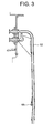
- FIG. 3 is a view showing a mounted condition of a pressure roller according to the embodiment of the present invention
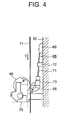
- FIG. 4 is a schematic view of the pressure guide device according to the embodiment of the present invention.
- reference numeral 11 denotes the packaging material
- reference numeral 52 denotes a filling pipe, which functions as a support member
- reference numeral 65 denotes a pressure roller, which serves as a first rotary member, is supported by a support mechanism 68 while being disposed at the inside of the joining surface of a longitudinally sealed portion of the packaging material 11 which has just been longitudinally sealed, and presses the longitudinally sealed region.
- the support mechanism 68 includes a bracket 69, which is attached to the filling pipe 52 at a predetermined position; a tension rod 71, which serves as a force-applying member and is disposed in such a manner as to extend downward from the bracket 69; a support member 72, which supports the tension rod 71 and is attached to the filling pipe 52 at a position corresponding to an intermediate portion of the tension rod 71; and a rotation support member 73, which is attached to a tip end (a lower end in FIG. 4) of the tension rod 71 and supports the pressure roller 65 such that the pressure roller 65 is rotatable in the direction of arrow A.
- the tension rod 71 applies a predetermined force to the packaging material 11 so as to press the packaging material 11 radially outward.
- Reference 66 denotes a counter roller, which serves as a second rotary member, is disposed in opposition to the pressure roller 65 with the packaging material 11 pinched therebetween, and receives a pressing force applied by the pressure roller 65.
- the counter roller 66 is supported on a frame of the filling machine by means of a support member 75, in such a manner as to be rotatable in the direction of arrow B.
- the pressure roller 65 and the counter roller 66 are rotated with the packaging material 11 and the strip tape 34 (FIG. 1) pinched therebetween, thereby bringing the surface of an overlap of the longitudinally sealed region and the affixal surface of the strip tape 34 into close contact with each other.
- the packaging material 11 is sealed by the longitudinal sealing device 55, the packaging material 11, the strip tape 34, etc. are heated, so that a resin, such as polyethylene resin, used to form the innermost layers of the packaging material 11, the strip tape 34, etc. may in some cases stick to the outer circumferential surface of the pressure roller 65. In this case, resistance is applied to the pressure roller 65 and reduces the rotational speed of the pressure roller 65.
- a resin such as polyethylene resin
- a plurality of permanent magnets 81 are circumferentially disposed in the pressure roller 65 to be located in the vicinity of the outer circumferential surface of the pressure roller 65, or to be exposed at the circumferential surface of the pressure roller 65, such that the N-pole and the S-pole are alternately oriented outward.
- the counter roller 66 assumes the form of a hollow body.
- a magnetic sensor 82 which serves as a detector and as a rotation detection signal generator, is disposed within the counter roller 66 at a predetermined position located in opposition to the packaging material 11 and in the vicinity of the pressure roller 65 and is fixed to the frame of the filling machine.
- the magnetic sensor 82 is formed of, for example, a Hall element.
- the magnetic sensor 82 As the pressure roller 65 is rotated, the N-poles and the S-poles of the permanent magnets 81 alternately move to a position located in opposition to the magnetic sensor 82. Accordingly, the magnetic sensor 82 generates a rotation detection signal which varies periodically, and outputs the signal to a control section 83.
- an unillustrated monitoring processing means of the control section 83 performs monitoring processing; i.e., the monitoring processing means records, on a recording device 84 as a reference signal, a rotation detection signal detected when the pressure roller 65 is rotated normally; subsequently, reads a rotation detection signal at predetermined timing; and compares the read rotation detection signal with the reference signal to thereby judge whether the pressure roller 65 is rotated normally.
- the monitoring processing means detects abnormality of rotation of the pressure roller 65, and an unillustrated report processing means of the control section 83 performs report processing; i.e., the report processing means generates an alarm signal and sends the signal to an alarm device 85 so as to report occurrence of the abnormality to an operator.
- the permanent magnets 81 are disposed in the pressure roller 65, and the magnetic sensor 82 generates a rotation detection signal in association with movement of the permanent magnets 81 effected by rotation of the pressure roller 65.
- the present invention is not limited thereto.
- permanent magnets may be disposed in the counter roller 66 while a magnetic sensor is disposed at a predetermined position. In this case, the magnetic sensor generates a rotation detection signal in association with movement of the permanent magnets effected by rotation of the counter roller 66.
- permanent magnets may be disposed in both the pressure roller 65 and the counter roller 66.
- the present invention can be applied to a packaging-container-manufacturing apparatus.
Landscapes
- Engineering & Computer Science (AREA)
- Mechanical Engineering (AREA)
- Chemical & Material Sciences (AREA)
- Composite Materials (AREA)
- Containers And Plastic Fillers For Packaging (AREA)
- Package Closures (AREA)
- Basic Packing Technique (AREA)
Abstract
Description
- The present invention relates to a filling machine and a filling monitoring method.
- Conventionally, in production of packaging containers which contain food; for example, food having fluidity such as tea, juice, soup, or alcohol; i.e., fluid food, a web-like packaging material, a sheet-like packaging material, or the like is used, and the packaging material is formed into packaging containers by means of sealing at predetermined positions through heat sealing, ultrasonic sealing, or a like method. For example, in a filling machine, a web-like packaging material, when used, is formed into a tubular shape; while a strip tape is pressed against the tubular packaging material from inside, the tubular packaging material is sealed in the longitudinal direction by means of a longitudinal sealing device; while being filled with liquid food, the longitudinally sealed tubular packaging material is sealed and cut in the lateral direction at predetermined longitudinal intervals by means of a lateral sealing device, thereby yielding a pillow-like prototype container; and the prototype container is further formed into a predetermined shape, thereby completing a packaging container (refer to, for example, Patent Document 1).
- In the conventional filling machine, at a position located downstream of the longitudinal sealing device with respect to the conveyance direction of the tubular packaging material, a pressure roller is rotatably disposed inside the tubular packaging material which has just been sealed in the longitudinal direction, and presses a longitudinally sealed region of the tubular packaging material; and a counter roller is rotatably disposed outside the tubular packaging material in opposition to the pressure roller and receives a pressing force applied by the pressure roller. Accordingly, as the packaging material travels, the pressure roller and the counter roller rotate while pinching therebetween the packaging material and the strip tape, thereby bringing the surface of an overlap of the longitudinally sealed region of the packaging material and the affixal surface of the strip tape into close contact with each other.
Patent Document 1:Japanese Patent Application Laid-Open (kokai) No. 2001-18909 - However, in the conventional filling machine, since the longitudinal sealing device applies heat to the packaging material and the strip tape, a resin used to form the innermost layers of the packaging material and the strip tape; for example, polyethylene resin, may in some cases stick to the outer circumferential surface of the pressure roller. In this case, resistance is applied to the pressure roller and reduces the rotational speed of the pressure roller, thereby causing damage to the inner surfaces of the packaging material and the strip tape, or separation of a sticking resin piece and dropping of the resin piece into fluid food contained in the packaging material, potentially causing a deterioration in quality of the fluid food.
- An object of the present invention is to solve the above-mentioned problems in the conventional filling machine and to provide a filling machine and a filling monitoring method which can monitor the condition of a pressure roller and do not cause a deterioration in quality of fluid food.
- To achieve the above object, a filling machine of the present invention comprises a first rotary member rotatably disposed at the inside of a joining surface of a longitudinally sealed portion of a packaging material being fed; a second rotary member rotatably disposed in opposition to the first rotary member with the packaging material pinched therebetween; a rotation detection signal generator for generating a rotation detection signal in association with rotation of at least one of the first and second rotary members; and monitoring processing means for reading the rotation detection signal and detecting abnormality of rotation of at least one of the first and second rotary members.
- In another filling machine of the present invention, the first rotary member is a pressure roller having a permanent magnet. The second rotary member is a counter roller. The rotation detection signal generator generates a rotation detection signal in association with movement of the permanent magnet.
- In a further filling machine of the present invention, the monitoring processing means uses, as a reference signal, a rotation detection signal generated when the pressure roller is rotated normally; then reads a rotation detection signal at predetermined timing and compares the read rotation detection signal with the reference signal; and detects abnormality of rotation of the pressure roller when the comparison shows that the pressure roller is not rotated normally.
- A still another filling machine of the present invention further comprises report processing means for reporting occurrence of abnormality to an operator when abnormality of rotation of the pressure roller is detected.
- A filling monitoring method of the present invention comprises feeding a packaging material; rotating, in association with feed of the packaging material, a first rotary member at the inside of a joining surface of a longitudinally sealed portion of the packaging material; rotating, in association with feed of the packaging material, a second rotary member disposed in opposition to the first rotary member with the packaging material pinched therebetween; and reading a rotation detection signal generated in association with rotation of at least one of the first and second rotary members, and detecting abnormality of rotation of at least one of the first and second rotary members.
- According to the present invention, the filling machine comprises a first rotary member rotatably disposed at the inside of a joining surface of a longitudinally sealed portion of a packaging material being fed; a second rotary member rotatably disposed in opposition to the first rotary member with the packaging material pinched therebetween; a rotation detection signal generator for generating a rotation detection signal in association with rotation of at least one of the first and second rotary members; and monitoring processing means for reading the rotation detection signal and detecting abnormality of rotation of at least one of the first and second rotary members.
- In this case, since abnormality of rotation of at least one of the first and second rotary members is detected on the basis of the rotation detection signal generated in association with rotation of at least one of the first and second rotary members, the following problem is prevented: damage to the inner surfaces of the packaging material and a strip tape, or separation of a sticking resin piece and dropping of the resin piece into fluid food contained in the packaging material, with a resultant deterioration in quality of the fluid food.
-
- [FIG. 1] Conceptual view of a filling machine according to an embodiment of the present invention.
- [FIG. 2] Conceptual view showing a method of monitoring a pressure guide device according to the embodiment of the present invention.
- [FIG. 3] View showing a mounted condition of a pressure roller according to the embodiment of the present invention.
- [FIG. 4] Schematic view of the pressure guide device according to the embodiment of the present invention.
-
- 11: packaging material
- 65: pressure roller
- 66: counter roller
- 81: permanent magnet
- 82: magnetic sensor
- 83: control section
- An embodiment of the present invention will next be described in detail with reference to the drawings.
- FIG. 1 is a conceptual view of a filling machine according to the embodiment of the present invention.
- As shown in the drawing, a web-
like packaging material 11 in the form of areel 31 is accommodated in acassette 32 and set in an unillustrated delivery section of the filling machine via thecassette 32. Thepackaging material 11 assumes the form of a flexible laminate configured as follows: a paper substrate is covered on both surfaces with a polyethylene resin film; as needed, a barrier layer, such as an aluminum foil or a gas-barrier resin, is formed between the paper substrate and each film; and facing is printed on a region of thepackaging material 11 which corresponds to the facing surface of apackaging container 33. - The
packaging material 11 delivered from the delivery section is intermittently fed by an unillustrated feeder, which serves as feeding means. The fed packaging material travels to a strip-tape-affixingdevice 40 via a bending roller r1, a damper roller r2, and the like. The strip-tape-affixingdevice 40 affixes astrip tape 34 to an edge portion of thepackaging material 11. Subsequently, thepackaging material 11 travels to apaper tensioner 35 via bending rollers r3 and r4 and then travels to a bending roller r5. In the course of the travel, apunch device 36 punches holes in thepackaging material 11; an inner-tape-affixingdevice 37 affixes aninner tape 38 to thepackaging material 11 so as to seal the punch holes from inside; and a pull-tab-affixingdevice 41affixes pull tabs 42 to thepackaging material 11 so as to seal the punch holes from outside. - The
packaging material 11 travels to a sterilizingtank 61 via apaper tensioner 43 and bending rollers r6 and r7. In the sterilizingtank 61, thepackaging material 11 is sterilized by means of a sterilizing liquid, such as hydrogen peroxide.Reference numeral 62 denotes a bottom tray of the sterilizingtank 61. - Subsequently, the
packaging material 11 travels to anair knife 45 via calender rollers r8. Theair knife 45 dries thepackaging material 11. The driedpackaging material 11 travels to upper formingrings 48 via a bending roller r9, a crease roller r10, and a bending roller r11. Thepackaging material 11 is gradually deformed into a tubular shape by means of the upper formingrings 48, movable formingrings 49, split formingrings 50, and a lower formingring 51. In the course of the deformation, alongitudinal sealing device 55 longitudinally seals thepackaging material 11, and a fluid food supplied through afilling pipe 52 is filled into thetubular packaging material 11. - The
packaging material 11 filled with the fluid food travels to apressure guide device 64, which is disposed downstream of thelongitudinal sealing device 55 with respect to the conveyance direction of thepackaging material 11. Thepressure guide device 64 includes an unillustrated pressure roller, which is disposed at the inside of a joining surface of a longitudinally sealed portion of thepackaging material 11 being fed and serves as a first rotary member, and acounter roller 66, which is disposed in opposition to the pressure roller with thepackaging material 11 pinched therebetween and serves as a second rotary member. As thepackaging material 11 travels, the surface of the overlap of the longitudinally sealed region of thepackaging material 11 and the affixal surface of thestrip tape 34 are brought into close contact with each other. - Subsequently, while being guided by tube support rollers r12, the
packaging material 11 travels to a sealing-cutting section p1. In the sealing-cutting section p1, while pinching thepackaging material 11, an unillustrated sealing-cutting device laterally seals and cuts thepackaging material 11 at predetermined longitudinal intervals so as to form a pillow-like prototype container 23. Theprototype container 23 is sent to a final forming-conveyingapparatus 58. While being conveyed on the final forming-conveyingapparatus 58, theprototype container 23 is formed into a predetermined shape, thereby completing thepackaging container 33 which contains a fixed amount of fluid food. - Next, the
pressure guide device 64 will be described in detail. - FIG. 2 is a conceptual view showing a method of monitoring a pressure guide device according to the embodiment of the present invention; FIG. 3 is a view showing a mounted condition of a pressure roller according to the embodiment of the present invention; and FIG. 4 is a schematic view of the pressure guide device according to the embodiment of the present invention.
- In the drawings,
reference numeral 11 denotes the packaging material;reference numeral 52 denotes a filling pipe, which functions as a support member; andreference numeral 65 denotes a pressure roller, which serves as a first rotary member, is supported by asupport mechanism 68 while being disposed at the inside of the joining surface of a longitudinally sealed portion of thepackaging material 11 which has just been longitudinally sealed, and presses the longitudinally sealed region.
Thesupport mechanism 68 includes abracket 69, which is attached to thefilling pipe 52 at a predetermined position; atension rod 71, which serves as a force-applying member and is disposed in such a manner as to extend downward from thebracket 69; asupport member 72, which supports thetension rod 71 and is attached to thefilling pipe 52 at a position corresponding to an intermediate portion of thetension rod 71; and arotation support member 73, which is attached to a tip end (a lower end in FIG. 4) of thetension rod 71 and supports thepressure roller 65 such that thepressure roller 65 is rotatable in the direction of arrow A. Thetension rod 71 applies a predetermined force to thepackaging material 11 so as to press thepackaging material 11 radially outward. -
Reference 66 denotes a counter roller, which serves as a second rotary member, is disposed in opposition to thepressure roller 65 with thepackaging material 11 pinched therebetween, and receives a pressing force applied by thepressure roller 65. Thecounter roller 66 is supported on a frame of the filling machine by means of asupport member 75, in such a manner as to be rotatable in the direction of arrow B. - Accordingly, as the
packaging material 11 is fed in the direction of arrow C, thepressure roller 65 and thecounter roller 66 are rotated with thepackaging material 11 and the strip tape 34 (FIG. 1) pinched therebetween, thereby bringing the surface of an overlap of the longitudinally sealed region and the affixal surface of thestrip tape 34 into close contact with each other. - Meanwhile, when the
packaging material 11 is sealed by thelongitudinal sealing device 55, thepackaging material 11, thestrip tape 34, etc. are heated, so that a resin, such as polyethylene resin, used to form the innermost layers of thepackaging material 11, thestrip tape 34, etc. may in some cases stick to the outer circumferential surface of thepressure roller 65. In this case, resistance is applied to thepressure roller 65 and reduces the rotational speed of thepressure roller 65. - If the condition is left without taking any measure thereagainst, there may arise damage to the inner surfaces of the
packaging material 11 and thestrip tape 34, or separation of a sticking resin piece and dropping of the resin piece into fluid food contained in thepackaging material 11, potentially causing a deterioration in quality of the fluid food. - In order to cope with the problem, a plurality of
permanent magnets 81 are circumferentially disposed in thepressure roller 65 to be located in the vicinity of the outer circumferential surface of thepressure roller 65, or to be exposed at the circumferential surface of thepressure roller 65, such that the N-pole and the S-pole are alternately oriented outward. Thecounter roller 66 assumes the form of a hollow body. Amagnetic sensor 82, which serves as a detector and as a rotation detection signal generator, is disposed within thecounter roller 66 at a predetermined position located in opposition to thepackaging material 11 and in the vicinity of thepressure roller 65 and is fixed to the frame of the filling machine. Themagnetic sensor 82 is formed of, for example, a Hall element. As thepressure roller 65 is rotated, the N-poles and the S-poles of thepermanent magnets 81 alternately move to a position located in opposition to themagnetic sensor 82. Accordingly, themagnetic sensor 82 generates a rotation detection signal which varies periodically, and outputs the signal to acontrol section 83. - In the case where no resistance is applied to the
pressure roller 65 and thus thepressure roller 65 is rotated normally, as thepackaging material 11 is fed, the traveling speed of thepackaging material 11 and the circumferential speed of thepressure roller 65 are equal to each other, so that a peak value appears in the rotation detection signal in a fixed cycle. By contrast, in the case where resistance is applied to thepressure roller 65 and thus thepressure roller 65 fails to be rotated normally, as thepackaging material 11 is fed, the traveling speed of thepackaging material 11 and the circumferential speed of thepressure roller 65 do not become equal to each other, and variations arise in a cycle of appearance of the peak value. - In order to cope with the above problem, an unillustrated monitoring processing means of the
control section 83 performs monitoring processing; i.e., the monitoring processing means records, on arecording device 84 as a reference signal, a rotation detection signal detected when thepressure roller 65 is rotated normally; subsequently, reads a rotation detection signal at predetermined timing; and compares the read rotation detection signal with the reference signal to thereby judge whether thepressure roller 65 is rotated normally. - When the
pressure roller 65 is not rotated normally, the monitoring processing means detects abnormality of rotation of thepressure roller 65, and an unillustrated report processing means of thecontrol section 83 performs report processing; i.e., the report processing means generates an alarm signal and sends the signal to analarm device 85 so as to report occurrence of the abnormality to an operator. - According to the present embodiment, the
permanent magnets 81 are disposed in thepressure roller 65, and themagnetic sensor 82 generates a rotation detection signal in association with movement of thepermanent magnets 81 effected by rotation of thepressure roller 65. However, the present invention is not limited thereto. For example, permanent magnets may be disposed in thecounter roller 66 while a magnetic sensor is disposed at a predetermined position. In this case, the magnetic sensor generates a rotation detection signal in association with movement of the permanent magnets effected by rotation of thecounter roller 66. Further alternatively, permanent magnets may be disposed in both thepressure roller 65 and thecounter roller 66. - The present invention is not limited to the above-described embodiment. Numerous modifications and variations of the present invention are possible in light of the spirit of the present invention, and they are not excluded from the scope of the present invention.
- The present invention can be applied to a packaging-container-manufacturing apparatus.
Claims (5)
- A filling machine comprising:(a) a first rotary member rotatably disposed at the inside of a joining surface of a longitudinally sealed portion of a packaging material being fed;(b) a second rotary member rotatably disposed in opposition to the first rotary member with the packaging material pinched therebetween;(c) a rotation detection signal generator for generating a rotation detection signal in association with rotation of at least one of the first and second rotary members; and(d) monitoring processing means for reading the rotation detection signal and detecting abnormality of rotation of at least one of the first and second rotary members.
- A filling machine according to claim 1, wherein:(a) the first rotary member is a pressure roller having a permanent magnet;(b) the second rotary member is a counter roller; and(c) the rotation detection signal generator generates a rotation detection signal in association with movement of the permanent magnet.
- A filling machine according to claim 1, wherein the monitoring processing means uses, as a reference signal, a rotation detection signal generated when the pressure roller is rotated normally; then reads a rotation detection signal at predetermined timing and compares the read rotation detection signal with the reference signal; and detects abnormality of rotation of the pressure roller when the comparison shows that the pressure roller is not rotated normally.
- A filling machine according to claim 1, further report comprising processing means for reporting occurrence of abnormality to an operator when abnormality of rotation of the pressure roller is detected.
- A filling monitoring method comprising:(a) feeding a packaging material;(b) rotating, in association with feed of the packaging material, a first rotary member at the inside of a joining surface of a longitudinally sealed portion of the packaging material;(c) rotating, in association with feed of the packaging material, a second rotary member disposed in opposition to the first rotary member with the packaging material pinched therebetween; and(d) reading a rotation detection signal generated in association with rotation of at least one of the first and second rotary members, and detecting abnormality of rotation of at least one of the first and second rotary members.
Applications Claiming Priority (2)
| Application Number | Priority Date | Filing Date | Title |
|---|---|---|---|
| JP2004366750A JP4563166B2 (en) | 2004-12-17 | 2004-12-17 | Filling machine and filling monitoring method |
| PCT/JP2005/022469 WO2006064702A1 (en) | 2004-12-17 | 2005-12-07 | Filling machine and filling monitoring method |
Publications (3)
| Publication Number | Publication Date |
|---|---|
| EP1826124A1 true EP1826124A1 (en) | 2007-08-29 |
| EP1826124A4 EP1826124A4 (en) | 2010-06-02 |
| EP1826124B1 EP1826124B1 (en) | 2012-07-04 |
Family
ID=36587760
Family Applications (1)
| Application Number | Title | Priority Date | Filing Date |
|---|---|---|---|
| EP05814541A Expired - Lifetime EP1826124B1 (en) | 2004-12-17 | 2005-12-07 | Filling machine and filling monitoring method |
Country Status (6)
| Country | Link |
|---|---|
| US (1) | US7673434B2 (en) |
| EP (1) | EP1826124B1 (en) |
| JP (1) | JP4563166B2 (en) |
| CN (1) | CN100522749C (en) |
| BR (1) | BRPI0518546A2 (en) |
| WO (1) | WO2006064702A1 (en) |
Cited By (3)
| Publication number | Priority date | Publication date | Assignee | Title |
|---|---|---|---|---|
| WO2009144168A1 (en) * | 2008-05-28 | 2009-12-03 | Tetra Laval Holdings & Finance S.A. | Packaging machine |
| EP3015375A1 (en) * | 2014-10-31 | 2016-05-04 | Tipper Tie, Inc. | Systems with wheel saddles that can cooperate with wheels of encodres and related devices and methods |
| EP3130323A1 (en) * | 2007-10-23 | 2017-02-15 | Yuyama Mfg. Co., Ltd. | Drug delivery system, and drug delivery device |
Families Citing this family (7)
| Publication number | Priority date | Publication date | Assignee | Title |
|---|---|---|---|---|
| JP2008120435A (en) * | 2006-11-15 | 2008-05-29 | Nihon Tetra Pak Kk | Packaging filling apparatus and packaging filling method |
| JP2008137660A (en) * | 2006-11-29 | 2008-06-19 | Nihon Tetra Pak Kk | Packaging and filling equipment |
| US20090127323A1 (en) | 2007-11-15 | 2009-05-21 | Bernhard Zeiler | Packaging machine and packages made therewith |
| US20110177435A1 (en) * | 2010-01-20 | 2011-07-21 | International Business Machines Corporation | Photomasks having sub-lithographic features to prevent undesired wafer patterning |
| US20140260121A1 (en) * | 2013-03-15 | 2014-09-18 | Yukie Jaqueline Tokuda | Device and method for bagging a consumable product for steeping |
| US10232968B2 (en) | 2014-10-02 | 2019-03-19 | The Boeing Company | Packaging methods |
| US11110666B2 (en) | 2018-02-12 | 2021-09-07 | Tipper Tie, Inc. | Systems with external heat-seal assembly height adjustment control and related seal assemblies |
Family Cites Families (23)
| Publication number | Priority date | Publication date | Assignee | Title |
|---|---|---|---|---|
| JPS576322Y2 (en) * | 1977-02-09 | 1982-02-05 | ||
| JPS5826667B2 (en) | 1977-03-08 | 1983-06-04 | 松下電器産業株式会社 | semiconductor equipment |
| JPS63197806A (en) | 1987-02-12 | 1988-08-16 | Osaka Gas Co Ltd | Gas burner |
| JPH0451138Y2 (en) * | 1987-06-12 | 1992-12-02 | ||
| US4914893A (en) * | 1988-02-26 | 1990-04-10 | Strub Eric W | Large size container banding apparatus |
| JP2626309B2 (en) * | 1991-05-31 | 1997-07-02 | 日本精機株式会社 | Heat sealing equipment |
| US5557510A (en) * | 1993-11-29 | 1996-09-17 | Gehl Company | Control system for a large round baler |
| IT1273854B (en) * | 1994-12-16 | 1997-07-11 | Ima Spa | SYSTEM FOR THE FEEDING OF ITEMS IN THE CELLS OF A CAVE TAPE |
| SE503486C2 (en) * | 1995-01-10 | 1996-06-24 | Tetra Laval Holdings & Finance | Moving device for performing continuous longitudinal joint welding on a packaging material web |
| JPH09254911A (en) * | 1996-03-19 | 1997-09-30 | Komatsu Ltd | Continuous manufacturing method of roll-type sealed package with spout |
| JPH107110A (en) * | 1996-04-25 | 1998-01-13 | Shikoku Kakoki Co Ltd | Web heating device |
| JP3750759B2 (en) * | 1996-09-26 | 2006-03-01 | 株式会社イシダ | Bag making and packaging machine |
| US5809873A (en) * | 1996-11-18 | 1998-09-22 | Ovalstrapping, Inc. | Strapping machine having primary and secondary tensioning units and a control system therefor |
| GB9705770D0 (en) * | 1997-03-20 | 1997-05-07 | Scherer Corp R P | Gelatin encapsulation techniques |
| JP3974241B2 (en) * | 1997-11-10 | 2007-09-12 | 日本テトラパック株式会社 | Filling machine |
| JP3240297B1 (en) * | 1999-02-03 | 2001-12-17 | 高園産業株式会社 | Packaging paper and packaging paper roll |
| JP2001018909A (en) | 1999-07-07 | 2001-01-23 | Nihon Tetra Pak Kk | Flushing device |
| JP3464195B2 (en) * | 2000-06-23 | 2003-11-05 | 株式会社村田製作所 | Magnetic sensor, magnetic sensor device, and torque sensor |
| PT1177976E (en) * | 2000-07-03 | 2004-04-30 | Tetra Laval Holdings & Finance | PACKAGING MACHINER FOR CONTINUOUSLY PRODUCING SEALED PACKAGING OF A FOOD PRODUCT THAT CAN BE DUMPED AND PHOTOELECTRIC CHARACTERIZATION CELLS THAT CAN BE SCHEDULED |
| JP2002264205A (en) * | 2001-03-08 | 2002-09-18 | Kureha Chem Ind Co Ltd | Apparatus and method for detecting sealing contact pressure, correcting and sealing |
| US6925893B2 (en) * | 2002-09-17 | 2005-08-09 | The Furukawa Electric Co., Ltd. | Rotation sensor |
| DE102004032183B4 (en) * | 2004-07-02 | 2007-04-12 | Poly-Clip System Gmbh & Co Kg | Device for producing film tube from a foil strip |
| US7360344B2 (en) * | 2004-09-17 | 2008-04-22 | Fpna Acquisition Corporation | Method and apparatus for sleeve or band-type packaging of a compressible article |
-
2004
- 2004-12-17 JP JP2004366750A patent/JP4563166B2/en not_active Expired - Fee Related
-
2005
- 2005-12-07 WO PCT/JP2005/022469 patent/WO2006064702A1/en not_active Ceased
- 2005-12-07 EP EP05814541A patent/EP1826124B1/en not_active Expired - Lifetime
- 2005-12-07 US US11/791,636 patent/US7673434B2/en not_active Expired - Fee Related
- 2005-12-07 CN CNB2005800432362A patent/CN100522749C/en not_active Expired - Fee Related
- 2005-12-07 BR BRPI0518546-7A patent/BRPI0518546A2/en not_active IP Right Cessation
Cited By (5)
| Publication number | Priority date | Publication date | Assignee | Title |
|---|---|---|---|---|
| EP3130323A1 (en) * | 2007-10-23 | 2017-02-15 | Yuyama Mfg. Co., Ltd. | Drug delivery system, and drug delivery device |
| WO2009144168A1 (en) * | 2008-05-28 | 2009-12-03 | Tetra Laval Holdings & Finance S.A. | Packaging machine |
| CN102046474B (en) * | 2008-05-28 | 2013-03-13 | 利乐拉瓦尔集团及财务有限公司 | Packaging machine |
| US8707662B2 (en) | 2008-05-28 | 2014-04-29 | Tetra Laval Holdings & Finance S.A. | Packaging machine |
| EP3015375A1 (en) * | 2014-10-31 | 2016-05-04 | Tipper Tie, Inc. | Systems with wheel saddles that can cooperate with wheels of encodres and related devices and methods |
Also Published As
| Publication number | Publication date |
|---|---|
| BRPI0518546A2 (en) | 2008-11-25 |
| US20080092491A1 (en) | 2008-04-24 |
| WO2006064702A1 (en) | 2006-06-22 |
| JP2006168814A (en) | 2006-06-29 |
| JP4563166B2 (en) | 2010-10-13 |
| EP1826124A4 (en) | 2010-06-02 |
| US7673434B2 (en) | 2010-03-09 |
| EP1826124B1 (en) | 2012-07-04 |
| CN100522749C (en) | 2009-08-05 |
| CN101080347A (en) | 2007-11-28 |
Similar Documents
| Publication | Publication Date | Title |
|---|---|---|
| US12600512B2 (en) | Method for controlling the position of a material web edge | |
| US7673434B2 (en) | Filling machine and filling monitoring method | |
| JP5934116B2 (en) | Apparatus and method for feeding a web of packaging material | |
| EP4335758A1 (en) | Packaging machine and method for producing packages from a packaging material | |
| CN1188320C (en) | Unit for processing web of packaging material | |
| JP7563790B2 (en) | Vertical filling and packaging equipment | |
| EP1967451B1 (en) | Packaging-container manufacturing apparatus and packaging-container manufacturing method | |
| JP4869682B2 (en) | Packaging and filling machine | |
| JP2015048136A (en) | Pocket part formation device of blister pack and packaging device | |
| JP2009067459A (en) | Packaging and filling equipment | |
| JP2011046472A (en) | Sheet terminal end detection device | |
| JP2776454B2 (en) | Shape displacement detector for filled packaging bags | |
| EP4335757A1 (en) | Packaging machine and method for producing packages from a packaging material | |
| JPH0651498B2 (en) | Film feeder structure of packaging equipment | |
| CA1314001C (en) | Method and apparatus for forming fw type back seals | |
| JP2003200903A (en) | Preforming device | |
| EP3822071A1 (en) | Unit and method for applying opening devices to a web of packaging material | |
| JP2004345690A (en) | Filling and sealing device | |
| JP2633186B2 (en) | Tablet packaging equipment | |
| JP2010120695A (en) | Wrapping filling device and wrapping filling method | |
| JP2007091324A (en) | Filling machine control device and filling machine control method | |
| JP2008137660A (en) | Packaging and filling equipment | |
| JP2003182708A (en) | Sealing device | |
| JP2019026373A (en) | Bag making filling and packaging machine | |
| HK1024454B (en) | Bag-producing apparatus and method of producing foil bags |
Legal Events
| Date | Code | Title | Description |
|---|---|---|---|
| PUAI | Public reference made under article 153(3) epc to a published international application that has entered the european phase |
Free format text: ORIGINAL CODE: 0009012 |
|
| 17P | Request for examination filed |
Effective date: 20070531 |
|
| AK | Designated contracting states |
Kind code of ref document: A1 Designated state(s): DE FR GB IT |
|
| DAX | Request for extension of the european patent (deleted) | ||
| RBV | Designated contracting states (corrected) |
Designated state(s): DE FR GB IT |
|
| A4 | Supplementary search report drawn up and despatched |
Effective date: 20100504 |
|
| RIC1 | Information provided on ipc code assigned before grant |
Ipc: B65B 57/04 20060101ALI20100427BHEP Ipc: B65B 57/00 20060101AFI20060704BHEP Ipc: B65B 9/10 20060101ALI20100427BHEP |
|
| RIC1 | Information provided on ipc code assigned before grant |
Ipc: B65B 57/04 20060101ALI20110902BHEP Ipc: B65B 57/00 20060101AFI20110902BHEP Ipc: B65B 9/10 20060101ALI20110902BHEP |
|
| GRAP | Despatch of communication of intention to grant a patent |
Free format text: ORIGINAL CODE: EPIDOSNIGR1 |
|
| RAP1 | Party data changed (applicant data changed or rights of an application transferred) |
Owner name: TETRA LAVAL HOLDINGS & FINANCE S.A. |
|
| GRAS | Grant fee paid |
Free format text: ORIGINAL CODE: EPIDOSNIGR3 |
|
| GRAA | (expected) grant |
Free format text: ORIGINAL CODE: 0009210 |
|
| AK | Designated contracting states |
Kind code of ref document: B1 Designated state(s): DE FR GB IT |
|
| REG | Reference to a national code |
Ref country code: GB Ref legal event code: FG4D |
|
| REG | Reference to a national code |
Ref country code: DE Ref legal event code: R096 Ref document number: 602005035041 Country of ref document: DE Effective date: 20120830 |
|
| PGFP | Annual fee paid to national office [announced via postgrant information from national office to epo] |
Ref country code: DE Payment date: 20121205 Year of fee payment: 8 |
|
| PGFP | Annual fee paid to national office [announced via postgrant information from national office to epo] |
Ref country code: IT Payment date: 20121213 Year of fee payment: 8 Ref country code: GB Payment date: 20121205 Year of fee payment: 8 |
|
| PGFP | Annual fee paid to national office [announced via postgrant information from national office to epo] |
Ref country code: FR Payment date: 20130107 Year of fee payment: 8 |
|
| PLBE | No opposition filed within time limit |
Free format text: ORIGINAL CODE: 0009261 |
|
| STAA | Information on the status of an ep patent application or granted ep patent |
Free format text: STATUS: NO OPPOSITION FILED WITHIN TIME LIMIT |
|
| 26N | No opposition filed |
Effective date: 20130405 |
|
| REG | Reference to a national code |
Ref country code: DE Ref legal event code: R097 Ref document number: 602005035041 Country of ref document: DE Effective date: 20130405 |
|
| REG | Reference to a national code |
Ref country code: DE Ref legal event code: R119 Ref document number: 602005035041 Country of ref document: DE |
|
| GBPC | Gb: european patent ceased through non-payment of renewal fee |
Effective date: 20131207 |
|
| REG | Reference to a national code |
Ref country code: FR Ref legal event code: ST Effective date: 20140829 |
|
| REG | Reference to a national code |
Ref country code: DE Ref legal event code: R119 Ref document number: 602005035041 Country of ref document: DE Effective date: 20140701 |
|
| PG25 | Lapsed in a contracting state [announced via postgrant information from national office to epo] |
Ref country code: DE Free format text: LAPSE BECAUSE OF NON-PAYMENT OF DUE FEES Effective date: 20140701 |
|
| PG25 | Lapsed in a contracting state [announced via postgrant information from national office to epo] |
Ref country code: FR Free format text: LAPSE BECAUSE OF NON-PAYMENT OF DUE FEES Effective date: 20131231 Ref country code: GB Free format text: LAPSE BECAUSE OF NON-PAYMENT OF DUE FEES Effective date: 20131207 |
|
| PG25 | Lapsed in a contracting state [announced via postgrant information from national office to epo] |
Ref country code: IT Free format text: LAPSE BECAUSE OF NON-PAYMENT OF DUE FEES Effective date: 20131231 |
|
| PG25 | Lapsed in a contracting state [announced via postgrant information from national office to epo] |
Ref country code: IT Free format text: LAPSE BECAUSE OF NON-PAYMENT OF DUE FEES Effective date: 20131207 |