EP1826104A2 - Anbindung für ein Transportgestell an ein Kraftfahrzeug - Google Patents
Anbindung für ein Transportgestell an ein Kraftfahrzeug Download PDFInfo
- Publication number
- EP1826104A2 EP1826104A2 EP07003751A EP07003751A EP1826104A2 EP 1826104 A2 EP1826104 A2 EP 1826104A2 EP 07003751 A EP07003751 A EP 07003751A EP 07003751 A EP07003751 A EP 07003751A EP 1826104 A2 EP1826104 A2 EP 1826104A2
- Authority
- EP
- European Patent Office
- Prior art keywords
- connection
- holder
- securing element
- body part
- connection according
- Prior art date
- Legal status (The legal status is an assumption and is not a legal conclusion. Google has not performed a legal analysis and makes no representation as to the accuracy of the status listed.)
- Granted
Links
- 238000003466 welding Methods 0.000 description 3
- 238000009434 installation Methods 0.000 description 2
- 238000004873 anchoring Methods 0.000 description 1
- 238000011161 development Methods 0.000 description 1
- 230000018109 developmental process Effects 0.000 description 1
- 230000003993 interaction Effects 0.000 description 1
- 238000004519 manufacturing process Methods 0.000 description 1
- 238000012986 modification Methods 0.000 description 1
- 230000004048 modification Effects 0.000 description 1
- 230000002787 reinforcement Effects 0.000 description 1
- 238000000926 separation method Methods 0.000 description 1
- 230000003313 weakening effect Effects 0.000 description 1
Images



Classifications
-
- B—PERFORMING OPERATIONS; TRANSPORTING
- B62—LAND VEHICLES FOR TRAVELLING OTHERWISE THAN ON RAILS
- B62D—MOTOR VEHICLES; TRAILERS
- B62D43/00—Spare wheel stowing, holding, or mounting arrangements
- B62D43/02—Spare wheel stowing, holding, or mounting arrangements external to the vehicle body
- B62D43/04—Spare wheel stowing, holding, or mounting arrangements external to the vehicle body attached beneath the vehicle body
Definitions
- the invention relates to a connection for a caddy to a motor vehicle according to claim 1, with at least one holder for the frame, which is connected via a fastening element with a body part.
- Such cradles for motor vehicles are known, inter alia, as roof, rear or underbody support. The latter are used in motor vehicles without Interventionradmulde particular as Adjustradkarfig.
- a cage is mounted, for example, in a minivan the compact car class under the rear substructure.
- a common connection provides for a rear hook and two front, simply screwed tabs in which cantilevers of the example of a (round) rod material produced cage are added.
- this cage also has to be designed for service, endurance and vehicle safety. All the more important, therefore, is the easily accessible - removable or movable - and, at the same time, stable connection of the cage to the substructure.
- An essential point of the invention consists in the fact that the inventor working here leaves the usually trodden way of a pure reinforcement of the connection. Notwithstanding this, it has been determined in several test series that the detachment in particular by twisting the holder - and thus a relaxation of the seat eg by a screw - supports, if not caused.
- the inventive idea provides to maintain the principle of the already described tabs with inserted round material, but to make the connection against rotation. As a result, in particular tilting moments are reduced, which act perpendicular to the longitudinal axis of a fastener that connects the bracket with the body part.
- the replacement of the connection for example, under the loads of a rear impact and a separation of the frame is virtually impossible.
- a corresponding securing element can in the variants described below be implemented easily and inexpensively, without an increase in the connection is required.
- connection thereafter, in a first advantageous embodiment of the connection is provided that the securing element is formed as an additional fastening element between the holder and the body part.
- the connection is strengthened.
- Such a connection can take place, for example, in the form of a double threaded connection of the holder.
- Such a securing element is preferably designed as a screw or rivet connection and particularly, which also preferably corresponds to the connection of the fastener. Since a tool change is eliminated, the installation of the connection is simplified.
- the securing element forms a stop between the holder and the body part.
- the element is either firmly connected to the body or with the holder such as welded, and abuts against an outer contour of the other part. Also, a twisting of the two parts against each other is practically impossible.
- a stop is also easy and inexpensive to implement in various ways, as will be described below.
- the securing element is preferably plate-shaped and fastened there to the holder or the body part, where it counteracts a potential rotation of the holder most effectively. This can be done eg by welding to the bodywork.
- the plate-like expression of the element while both the anchorage and the abutment surface is increased, which ensures a particularly high stability.
- the load transfer on the securing element - and thus the stability of the connection - is preferably increased in both cases by a stop which forms a form-fitting profile system.
- the securing element is alternatively possible on the bracket or the body part
- an attachment to the body is preferred.
- a hitherto conventional holder can be used, which, however, rests against rotation against the body part after assembly.
- a required shape of the body part at the installation site is hardly significant in terms of cost.
- the securing element for forming a stop also basically engage in the holder or can pass through this, a concern with one of its outer edges is preferred. This eliminates corresponding modifications to the commonly used holder, such as a (pass) hole or a slot.
- the securing element is designed as a form-fitting profile connection between the holder and the body part.
- the connection can be determined, for example, by two intermeshing profiles with a wave-shaped or sawtooth-shaped contour, as a result of which a particularly high resistance to twisting of the holder is produced.
- this represents a particularly cost effective and effective backup.
- the body part is designed as a mounting bracket.
- the body part can be used as a stop for a holder side arranged fuse element, without the outer skin at this point request a suitable contour.
- the stop can also be particularly easily produced by a corresponding fold of the mounting bracket, which allows a larger contact surface.
- this is also particularly easy to provide with a locking profile, which prevents a mutual rotation of the parts in interaction with a correspondingly shaped surface of the holder. This results in a particularly simple, easy to install and cost-effective connection.
- a transport frame arranged on the underside of a vehicle is accessible, for example, by loosening screw connections.
- a movable and stable connection is achieved when the holder also has a tab on which the transport frame is rotatably mounted.
- a rotatability can also be produced if the holder has a hinge on which the transport frame is rotatably mounted.
- a securing element fastened to the body part can also be brought into abutment against the lug of the holder, whereby the lever counteracting a rotation of the holder can be elongated.
- the securing element is preferably designed pin-shaped to save space against a cross section of the tab.
- FIG. 1a shows a plan view of a known left and a right front connection of a spare wheel cage under the rear substructure of a motor vehicle.
- the connections are mirror images of each other, so that the reference numbers in the right connection unnecessary.
- Both connections comprise a respective holder 10 with a lug 11 connected thereto in the direction of travel.
- the holder 10 is fastened to an underlying body part 30 via a fastening element 20 - in this case by way of example a screw connection.
- a caddy - here a Optimizradhanfig (not shown) - is rotatably mounted on the lugs 15 via a rotation axis A, and can be solved on the rear side (in the direction of lower sheet edge) for inserting or removing the wheel.
- FIG. 1b shows the plan view of FIG. 1a with the deformed connections after a rear impact.
- a force acting on the rear side F deforms the axis of rotation A of the frame in the direction of travel, as a result of which the left and right-hand connection rotates following the upper arrows.
- the fasteners 20 and can be easily solved by the occurring tilting moments of the body part or slide the frame out of the tabs.
- connection according to the invention are based on a left-side connection, but are preferably also implemented on the right-hand connection.
- FIG. 2 shows a left-side connection, with a first securing element 40 according to the invention, as an additional fastening element - in this example as the fastener 20 as a screw - is formed.
- the securing element 40 prevents a potential twisting of a holder 10 'about the fastening element 20 during a deformation of the axis of rotation A, the arm of which is guided in the lug 11.
- the securing element in this case counteracts a rotation both by frictional pressing of the holder 10 against the body part 30, as well as in the form of a stop between the parts 10 and 20. Since the seat of the element 20 can not solve a weakening of the connection and the possibility of detachment is practically impossible. Such a connection is easy to manufacture and requires no additional installation-side expenses, so it is quick and inexpensive to implement.
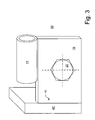
- FIG. 3 shows a left-side connection, with a second securing element 40 according to the invention, which is designed as a plate-shaped stop 41 relative to the holder 10.
- the long stop surface counteracts a potential twisting of the holder 10 particularly effectively, so that a detachment of the connection in a rear impact is practically impossible.
- a rotation of the holder 10 in both directions - ie with and counterclockwise - blocked whereby a detachment of the connection is practically impossible regardless of the actual deformation of the axis of rotation.
- the element 40 is welded to the body part 30 in this example.
- the stop 41 can also be provided by a corresponding profiling of the body part 30 itself.
- the solution presented here is particularly simple and inexpensive to implement, while also extremely effective.
- FIG. 4 finally shows the connection of FIG. 3 with a third securing element 40 "according to the invention, which is designed in the form of a pin and forms a stop 41 'with respect to the tab 15.
- the securing element 40" is likewise welded to the body part 30 in this example This also effectively prevents a potential twisting of the holder 10, with the securing element 40 "also being arranged in a space-saving manner between the holder 10 and the tab 11. Also, this arrangement excludes - similar to the plate-like expression - a twisting of the holder 10 in both directions, which reliably prevents detachment of the connection.
- connections according to the invention are characterized by particular stability and at the same time offer good accessibility to the - demountable or mobile - transport frame. A replacement of the connections in case of an accident event is practically excluded.
Landscapes
- Engineering & Computer Science (AREA)
- Chemical & Material Sciences (AREA)
- Combustion & Propulsion (AREA)
- Transportation (AREA)
- Mechanical Engineering (AREA)
- Body Structure For Vehicles (AREA)
- Fittings On The Vehicle Exterior For Carrying Loads, And Devices For Holding Or Mounting Articles (AREA)
Abstract
Description
- Die Erfindung betrifft eine Anbindung für ein Transportgestell an ein Kraftfahrzeug nach Anspruch 1, mit wenigstens einer Halterung für das Gestell, die über ein Befestigungselement mit einem Karosserieteil verbunden ist.
- Derartige Transportgestelle für Kraftfahrzeuge sind unter anderem als Dach-, Heck- oder Unterbodenträger bekannt. Letztere werden bei Kraftfahrzeugen ohne Ersatzradmulde insbesondere als Ersatzradkäfig genutzt. Ein solcher Käfig wird zB bei einem Minivan der Kompaktwagenklasse unter dem Heckunterbau angebracht. Eine übliche Anbindung sieht dabei einen hinteren Haken und zwei vordere, einfach geschraubte Laschen vor, in denen Ausleger des zB aus einem (Rund)Stangenmaterial hergestellten Käfigs aufgenommen werden. Wie jedes andere Gestell muss auch dieser Käfig für die Aufgabenbereiche Service, Dauerlauf und Fahrzeugsicherheit ausgelegt werden. Um so wichtiger ist damit die einerseits gut zugängliche - abnehmbare oder bewegliche - und andererseits gleichzeitig stabile Anbindung des Käfigs an den Unterbau.
- Im Falle eines Heckaufpralls haben sich allerdings die üblichen vorderen Anbindungen eines derartigen Transportgestells als ungünstig erwiesen, da dieses sich bei einer auftretenden Last leicht aus seinen Verankerungen löst. Dem wurde bislang durch eine entsprechend stärkere Verschraubung, Vernietung, Verschweißung oÄ entgegengewirkt, die teuer und aufwendig ist, ohne aber notwendigerweise auch eine Ablösung zu verhindern.
- Es ist Aufgabe der vorliegenden Erfindung, eine Anbindung für ein Transportgestell an ein Kraftfahrzeug zu schaffen, deren Stabilität erhöht und die einfach und kostengünstig zu realisieren ist.
- Diese Aufgabe wird durch eine Anbindung mit einem Sicherungselement gelöst, das so ausgebildet angeordnet ist, dass die Halterung bei einer Deformation des Gestells gegen ein Verdrehen um das Befestigungselement blockiert ist.
- Ein wesentlicher Punkt der Erfindung besteht dabei darin, dass der hier tätige Erfinder den üblicherweise beschrittenen Weg einer reinen Verstärkung der Anbindung verlässt. Abweichend davon wurde nämlich in mehreren Versuchsreihen festgestellt, dass die Ablösung insbesondere durch Verdrehen der Halterung - und damit eine Lockerung des Sitzes zB von einer Schraubverbindung - unterstützt, wenn nicht gar verursacht wird. Der erfinderische Gedanke sieht dagegen vor, das Prinzip zB der bereits geschilderten Laschen mit eingelegtem Rundmaterial beizubehalten, aber die Anbindung verdrehsicher zu gestalten. Dadurch werden insbesondere Kippmomente reduziert, die senkrecht zur Längsachse eines Befestigungselements wirken, das die Halterung mit dem Karosserieteil verbindet. Die Ablösung der Anbindung zB unter den Lasten eines Heckaufpralls und ein Separieren des Gestells ist praktisch ausgeschlossen. Ein entsprechendes Sicherungselement kann in den nachfolgend beschriebenen Varianten einfach und kostengünstig realisiert werden, ohne dass eine Verstärkung der Anbindung erforderlich ist.
- Bevorzugte Weiterbildungen der Anbindung sind in den Ansprüchen 2 bis 12 angegeben.
- Danach ist in einer ersten vorteilhaften Ausführungsform der Anbindung vorgesehen, dass das Sicherungselement als zusätzliches Befestigungselement zwischen der Halterung und dem Karosserieteil ausgebildet ist. Damit ist ein Verdrehen der Halterung praktisch ausgeschlossen; gleichzeitig ist die Anbindung verstärkt. Eine solche Anbindung kann zB in Form einer Zweifachverschraubung der Halterung erfolgen.
- Ein derartiges Sicherungselement ist bevorzugt als Schraub- oder Nietverbindung und besonders ausgeführt, die zudem bevorzugt der Verbindungsart des Befestigungselements entspricht. Da ein Werkzeugwechsel entfällt, wird die Montage der Anbindung vereinfacht.
- In einer zweiten vorteilhaften Ausführungsform bildet das Sicherungselement einen Anschlag zwischen der Halterung und dem Karosserieteil. Dazu ist das Element entweder mit der Karosserie oder mit der Halterung fest verbunden wie zB verschweißt, und liegt gegen eine Außenkontur des jeweils anderen Teils an. Auch dadurch wird ein Verdrehen der beiden Teile gegeneinander praktisch ausgeschlossen. Ein solcher Anschlag ist zudem auf verschiedene Arten einfach und kostengünstig zu realisieren, wie im Folgenden beschrieben wird.
- Danach ist das Sicherungselement bevorzugt plattenförmig ausgebildet und dort an der Halterung oder dem Karosserieteil befestigt, wo es einer potentiellen Drehung der Halterung am effektivsten entgegenwirkt. Dies kann zB durch Verschweißen mit dem Karosserieuntergrund geschehen. Durch die plattenförmige Ausprägung des Elements wird dabei sowohl die Verankerung als auch die Anschlagfläche erhöht, was für eine besonders große Stabilität sorgt. Die Lastübertragung am Sicherungselement - und dadurch die Stabilität der Verbindung - wird in beiden Fällen bevorzugt durch einen Anschlag erhöht, der eine formschlüssige Profilanlage bildet.
- Obgleich eine Verankerung des Sicherungselements alternativ an der Halterung oder dem Karosserieteil möglich ist, ist eine Befestigung an der Karosserie bevorzugt. Neben einem Verschweißen kann dies alternativ auch dadurch geschehen, dass das Sicherungselement einstückig mit der Karosserie ausgebildet ist, zB durch eine entsprechende Profilgebung der letzteren. Dadurch kann eine bislang übliche Halterung verwendet werden, die nach Montage allerdings verdrehsicher gegen das Karosserieteil anliegt. Eine erforderliche Formgebung des Karosserieteils an der Montagestelle fällt kostenmäßig kaum ins Gewicht.
- Obwohl das Sicherungselement zum Bilden eines Anschlags auch grundsätzlich in die Halterung eingreifen oder diese durchgreifen kann, ist ein Anliegen an einer derer Außenkanten bevorzugt. Dadurch entfallen entsprechende Modifikationen an der üblicherweise verwendeten Halterung, wie zB eine (Pass)Bohrung oder ein Schlitz.
- In einer dritten bevorzugten Ausführungsform ist das Sicherungselement als formschlüssige Profilverbindung zwischen der Halterung und dem Karosserieteil ausgebildet. Die Verbindung kann zB durch zwei ineinandergreifende Profile mit wellen- oder sägezahnförmiger Kontur bestimmt sein, wodurch eine besonders hohe Verdrehsicherheit der Halterung erzeugt wird. Da sich zusätzliche Teile erübrigen, stellt dies eine besonders kostengünstige und effektive Sicherung dar.
- Gleich mehrere Vorteile entstehen, wenn das Karosserieteil als Montagewinkel ausgebildet ist. Zum einen entsteht eine Außenkante der Karosserie, die als Anschlag für ein halterungsseitig angeordnetes Sicherungselement nutzbar ist, ohne der Außenhaut an dieser Stelle eine dazu geeignete Kontur abzufordern. Alternativ lässt sich der Anschlag auch besonders einfach durch eine entsprechende Abkantung des Montagewinkels herstellen, die eine größere Anlagefläche erlaubt. Zudem ist dieser auch besonders einfach mit einem Rastprofil zu versehen, das im Zusammenspiel mit einer entsprechend gestalteten Oberfläche der Halterung ein gegenseitiges Verdrehen der Teile verhindert. Dadurch entsteht eine besonders einfache, montagefreundliche und kostengünstige Anbindung.
- Grundsätzlich ist ein unterseitig an einem Fahrzeug angeordnetes Transportgestell durch zB Lösen von Schraubverbindungen zugänglich. Eine bewegliche und gleichzeitig stabile Anbindung wird aber dadurch erreicht, wenn die Halterung zudem eine Lasche aufweist, an der das Transportgestell drehbar gelagert ist. Eine solche Drehbarkeit kann alternativ auch dadurch hergestellt werden, wenn die Halterung ein Scharnier aufweist, an der das Transportgestell drehbar gelagert ist.
- Gleich wie schon vorstehend beschrieben kann ein an dem Karosserieteil befestigtes Sicherungselement auch gegen die Lasche der Halterung in Anschlag gebracht werden, wodurch der einer Verdrehung der Halterung entgegenwirkende Hebel verlängerbar ist. Dabei ist das Sicherungselement bevorzugt stiftförmig ausgebildet, um platzsparend gegen einen Querschnitt der Lasche anzuliegen.
- Es bleibt darauf hinzuweisen, dass alle hier genannten Ausführungsformen untereinander kombinierbar sind, und deren spezifische Verbindung nur durch die Anforderungen des jeweiligen Einsatzzwecks bestimmt ist.
- Die Erfindung wird im Folgenden anhand von drei Ausführungsbeispielen näher erläutert, wobei auf die zugehörigen Zeichnungen Bezug genommen wird. Gleiche oder gleichwirkende Teile sind mit gleichen Bezugsziffern versehen. Es zeigen:
- Figur 1a
- eine Draufsicht auf eine bekannte linke und eine rechte vordere Anbindung eines Ersatzradkäfigs unter dem Heckunterbau eines Kraftfahrzeugs aus dem Stand der Technik;
- Figur 1b
- die Draufsicht der Figur 1a mit den deformierten Anbindungen nach einem Heckaufprall;
- Figur 2
- eine linksseitige Anbindung, mit einem erfindungsgemäßen Sicherungselement, das als zusätzliches Befestigungselement ausgebildet ist;
- Figur 3
- eine linksseitige Anbindung, mit einem erfindungsgemäßen Sicherungselement, das als plattenförmiger Anschlag gegenüber einer Halterung der Anbindung ausgebildet ist, und
- Figur 4
- die Anbindung der Figur 3, mit einem erfindungsgemäßen Sicherungselement, das als stiftförmiger Anschlag gegenüber einer Lasche der Anbindung ausgebildet ist.
- Die Figur 1a zeigt eine Draufsicht auf eine bekannte linke und eine rechte vordere Anbindung eines Ersatzradkäfigs unter dem Heckunterbau eines Kraftfahrzeugs. Die Anbindungen sind spiegelbildlich zueinander aufgebaut, so dass sich die Bezugsziffern in der rechten Anbindung erübrigen. Beide Anbindungen umfassen eine jeweilige Halterung 10 mit einer in Fahrtrichtung daran angebundenen Lasche 11. Die Halterung 10 ist über ein Befestigungselement 20 - hier beispielhaft eine Schraubverbindung - an einem darunter liegenden Karosserieteil 30 befestigt. Ein Transportgestell - hier ein Ersatzradkäfig (nicht gezeigt) - ist über eine Drehachse A an den Laschen 15 drehbar gelagert, und kann heckseitig (in Richtung unterer Blattrand) zum Einlegen bzw Entnehmen des Rads gelöst werden.
- Die Figur 1b zeigt die Draufsicht der Figur 1a mit den deformierten Anbindungen nach einem Heckaufprall. Eine heckseitig einwirkende Kraft F verformt die Drehachse A des Gestells in Fahrtrichtung, wodurch sich die linke und rechtsseitige Anbindung den oberen Pfeilen folgend dreht. Dadurch lockern sich die Befestigungselemente 20 und können sich durch die auftretenden Kippmomente leicht von dem Karosserieteil lösen oder das Gestell aus den Laschen rutschen.
- Die drei unterschiedlichen Ausführungsformen einer erfindungsgemäßen Anbindung gehen der Einfachheit halber von einer linksseitigen Anbindung aus, sind aber bevorzugt auch an der rechten Anbindung verwirklicht.
- Die Figur 2 zeigt eine linksseitige Anbindung, mit einem ersten erfindungsgemäßen Sicherungselement 40, das als zusätzliches Befestigungselement - in diesem Beispiel wie das Befestigungselement 20 als Schraubverbindung - ausgebildet ist. Das Sicherungselement 40 verhindert dabei ein potentielles Verdrehen einer Halterung 10' um das Befestigungselement 20 bei einer Deformation der Drehachse A, deren Ausleger in der Lasche 11 geführt ist. Das Sicherungselement wirkt dabei einer Verdrehung sowohl durch kraftschlüssige Pressung der Halterung 10 gegen das Karosserieteil 30, wie auch in Form eines Anschlags zwischen den Teilen 10 und 20 entgegen. Da sich der Sitz des Elements 20 nicht lösen kann, ist eine Schwächung der Anbindung und die Möglichkeit einer Ablösung praktisch ausgeschlossen. Eine solche Anbindung ist einfach herzustellen und erfordert keine zusätzlichen montageseitigen Aufwendungen, ist damit schnell und kostengünstig zu realisieren.
- Die Figur 3 zeigt eine linksseitige Anbindung, mit einem zweiten erfindungsgemäßen Sicherungselement 40, das als plattenförmiger Anschlag 41 gegenüber der Halterung 10 ausgebildet ist. Die lange Anschlagsfläche wirkt dabei einer potentiellen Verdrehung der Halterung 10 besonders effektiv entgegen, so dass eine Ablösung der Anbindung bei einem Heckaufprall praktisch ausgeschlossen ist. Darüber hinaus ist durch eine derartige Anordnung ein Verdrehen der Halterung 10 in beide Richtungen - also mit und entgegen dem Uhrzeigersinn - blockiert, wodurch eine Ablösung der Anbindung unabhängig von der tatsächlichen Verformung der Drehachse praktisch ausgeschlossen ist. Das Element 40 ist in diesem Beispiel mit dem Karosserieteil 30 verschweißt. Grundsätzlich kann der Anschlag 41 aber auch durch einen entsprechende Profilgebung des Karosserieteils 30 selbst zur Verfügung gestellt werden. Die hier vorgestellte Lösung ist aber besonders einfach und kostengünstig zu realisieren, dabei zudem äußerst wirksam.
- Die Figur 4 schließlich zeigt die Anbindung der Figur 3, mit einem dritten erfindungsgemäßen Sicherungselement 40", das stiftförmige ausgebildet ist und einen Anschlag 41' gegenüber der Lasche 15 bildet. Das Sicherungselement 40'' ist dazu in diesem Beispiel ebenfalls mit dem Karosserieteil 30 verschweißt. Auch damit wird eine potentielle Verdrehung der Halterung 10 wirksam verhindert, wobei das Sicherungselement 40" zudem platzsparend zwischen der Halterung 10 und der Lasche 11 angeordnet ist. Auch diese Anordnung schließt - ähnlich wie die plattenförmige Ausprägung - ein Verdrehen der Halterung 10 in beide Richtungen aus, was eine Ablösung der Anbindung sicher verhindert.
- Alle vorstehend beschriebenen Ausführungsformen lassen sich miteinander kombinieren und schließen sich nicht aus. Jede spezifische Kombination wird durch den gewünschten Einsatzzweck bestimmt. Die erfindungsgemäßen Anbindungen zeichnen sich durch besondere Stabilität aus und bieten gleichzeitig eine gute Zugänglichkeit zum - abnehmbaren oder beweglichen - Transportgestell. Eine Ablösung der Anbindungen im Fall eines Unfallereignisses wird praktisch ausgeschlossen.
-
- 10, 10'
- Halterung
- 11
- Lasche
- 20
- Befestigungselement
- 30
- Karosserieteil
- 40; 40'; 40"
- Sicherungselement
- 41; 41'
- Anschlag
- A
- Drehachse des Traggestells
- F
- Krafteinwirkung
Claims (15)
- Anbindung für ein Transportgestell an ein Kraftfahrzeug, mit wenigstens einer Halterung (10; 10') für das Gestell, die über ein Befestigungselement (20) mit einem Karosserieteil (30) verbunden ist, gekennzeichnet durch ein Sicherungselement (40; 40'; 40"), das so ausgebildet und angeordnet ist, dass die Halterung (10, 10') bei einer Deformation des Gestells gegen ein Verdrehen um das Befestigungselement (20) blockiert ist.
- Anbindung nach Anspruch 1, bei der das Sicherungselement (40) als zusätzliches Befestigungselement zwischen der Halterung (10') und dem Karosserieteil (30) ausgebildet ist.
- Anbindung nach Anspruch 1 oder 2, bei der das Sicherungselement (40) eine Schraub- oder Nietverbindung umfasst.
- Anbindung nach einem der vorstehenden Ansprüche, bei der das Sicherungselement (40') einen Anschlag (41) zwischen der Halterung (10) und dem Karosserieteil (30) bildet.
- Anbindung nach Anspruch 4, bei der das Sicherungselement (40') plattenförmig ausgebildet ist.
- Anbindung nach Anspruch 4 oder 5, bei der das Sicherungselement (40') an dem Karosserieteil (30) befestigt ist.
- Anbindung nach Anspruch 6, bei der das Sicherungselement (40') gegen eine Außenkante der Halterung (10) anliegt.
- Anbindung nach einem der vorstehenden Ansprüche, bei der das Sicherungselement als formschlüssige Profilverbindung zwischen der Halterung (10) und dem Karosserieteil (30) ausgebildet ist.
- Anbindung nach einem der vorstehenden Ansprüche, bei der das Karosserieteil (30) als Montagewinkel ausgebildet ist.
- Anbindung nach einem der vorstehenden Ansprüche, bei der die Halterung (10; 10') eine Lasche (11) aufweist, an der das Transportgestell drehbar gelagert ist.
- Anbindung nach einem der vorstehenden Ansprüche, bei der die Halterung (10; 10') ein Scharnier aufweist, an der das Transportgestell drehbar gelagert ist.
- Anbindung nach einem der Ansprüche 10 oder 11, bei der das Sicherungselement (40'') einen Anschlag (41') zwischen der Lasche (11) und dem Karosserieteil (30) bildet.
- Anbindung nach Anspruch 12, bei der das Sicherungselement (40'') stiftförmig ausgebildet ist.
- Anbindung nach Anspruch 12 oder 13, bei der das Sicherungselement (40'; 40'') an dem Karosserieteil (30) befestigt ist.
- Verwendung einer Anbindung nach einem der vorstehenden Ansprüche zur Aufhängung eines Ersatzradkäfigs an einem Kraftfahrzeug.
Applications Claiming Priority (1)
| Application Number | Priority Date | Filing Date | Title |
|---|---|---|---|
| DE200610008904 DE102006008904A1 (de) | 2006-02-27 | 2006-02-27 | Anbindung für ein Transportgestell an ein Kraftfahrzeug |
Publications (3)
| Publication Number | Publication Date |
|---|---|
| EP1826104A2 true EP1826104A2 (de) | 2007-08-29 |
| EP1826104A3 EP1826104A3 (de) | 2008-01-16 |
| EP1826104B1 EP1826104B1 (de) | 2012-08-01 |
Family
ID=38069287
Family Applications (1)
| Application Number | Title | Priority Date | Filing Date |
|---|---|---|---|
| EP20070003751 Not-in-force EP1826104B1 (de) | 2006-02-27 | 2007-02-23 | Anbindung für ein Transportgestell an ein Kraftfahrzeug |
Country Status (2)
| Country | Link |
|---|---|
| EP (1) | EP1826104B1 (de) |
| DE (1) | DE102006008904A1 (de) |
Citations (2)
| Publication number | Priority date | Publication date | Assignee | Title |
|---|---|---|---|---|
| FR342607A (fr) | 1904-04-25 | 1904-09-13 | Adolph Abraham | Dispositif de fermeture pour portes ou cloisons mobiles de derrière de véhicules |
| US5779117A (en) | 1996-10-04 | 1998-07-14 | Rogers; Gene R. | Tool box adapter |
Family Cites Families (7)
| Publication number | Priority date | Publication date | Assignee | Title |
|---|---|---|---|---|
| EP0566528A1 (de) * | 1992-04-14 | 1993-10-20 | Alusuisse-Lonza Services Ag | Plattform für Nutzfahrzeuge |
| JP2983147B2 (ja) * | 1994-10-24 | 1999-11-29 | 住友軽金属工業株式会社 | トラックあおり |
| DE19701091A1 (de) * | 1997-01-15 | 1997-07-24 | Werner Sattler | Transport- und Aufbewahrungsgestell für Fahrräder in liegender Haltung im Inneren eines PKW's |
| DE19930763B4 (de) * | 1999-07-02 | 2005-07-28 | Audi Ag | Teleskopträger mit Sollbruchstellen zur Lastaufnahme im Innenraum eines Kraftfahrzeuges |
| DE10100712B4 (de) * | 2001-01-10 | 2014-05-22 | Accuride International Gmbh | Teleskopschiene |
| DE10257797B3 (de) * | 2002-12-11 | 2004-07-01 | Daimlerchrysler Ag | Laderaum eines Kraftfahrzeugs |
| DE102004001366A1 (de) * | 2004-01-08 | 2005-08-04 | Bayerische Motoren Werke Ag | Lastschiene für den Laderaum eines Kraftfahrzeuges |
-
2006
- 2006-02-27 DE DE200610008904 patent/DE102006008904A1/de not_active Withdrawn
-
2007
- 2007-02-23 EP EP20070003751 patent/EP1826104B1/de not_active Not-in-force
Patent Citations (2)
| Publication number | Priority date | Publication date | Assignee | Title |
|---|---|---|---|---|
| FR342607A (fr) | 1904-04-25 | 1904-09-13 | Adolph Abraham | Dispositif de fermeture pour portes ou cloisons mobiles de derrière de véhicules |
| US5779117A (en) | 1996-10-04 | 1998-07-14 | Rogers; Gene R. | Tool box adapter |
Also Published As
| Publication number | Publication date |
|---|---|
| EP1826104B1 (de) | 2012-08-01 |
| EP1826104A3 (de) | 2008-01-16 |
| DE102006008904A1 (de) | 2007-08-30 |
Similar Documents
| Publication | Publication Date | Title |
|---|---|---|
| EP1701861B1 (de) | Antrieb einer sitzverstelleinrichtung für kraftfahrzeuge | |
| DE102007018715A1 (de) | Fahrzeugsitz | |
| DE3106821A1 (de) | In einem personenkraftwagen angeordneter sitz | |
| WO2008019788A1 (de) | Kraftfahrzeug mit zumindest einem längsträger | |
| DE102014214913B4 (de) | Längsträgervorrichtung zum Tragen eines Frontmotors in einem Kraftfahrzeug | |
| DE19858303B4 (de) | Vorbaustruktur für eine selbsttragende Rohbaukarosserie eines Personenkraftwagens | |
| EP3274213A1 (de) | Adapteranordung für einen fahrzeugsitz und fahrzeugsitz | |
| DE102010010585A1 (de) | Längseinsteller für einen Fahrzeugsitz mit Spindel und Spindelhalter | |
| EP1575806A1 (de) | Crashbox-kühleraufnahme | |
| EP0669244A1 (de) | Crashgünstige Aggregatlagerung | |
| EP3192723A1 (de) | Fahrwerk-hilfsrahmenanordnung zur verbesserung der crashsicherheit | |
| DE102008020051A1 (de) | Crashbox für eine Karosserie eines Kraftwagens | |
| DE102005060480B4 (de) | Kraftfahrzeugsitz | |
| EP1826104B1 (de) | Anbindung für ein Transportgestell an ein Kraftfahrzeug | |
| DE102018106419B4 (de) | Verstellvorrichtung | |
| DE10353449B4 (de) | Lagerbock, insbesondere Mittellager, zur schwenkbaren Anlenkung von Sitzlehnen in einem Fahrzeug, insbesondere zur schwenkbaren Anlenkung von getrennt umlegbaren Sitzlehnen einer Rücksitzbank eines Kraftfahrzeuges | |
| DE20209141U1 (de) | Griffeinrichtung für einen Fahrzeuginnenraum | |
| DE102018209467B4 (de) | Tragendes Fahrzeugrahmenbauteil mit verformbarem Befestigungsabschnitt und Kraftfahrzeug mit einem solchen tragenden Fahrzeugrahmenbauteil | |
| DE102009012237B4 (de) | Karosserie für ein Kraftfahrzeug | |
| EP0963309A1 (de) | Befestigungssystem für formintegrierte stossfänger | |
| DE102005047272B3 (de) | Fahrzeugsitz, insbesondere Kraftfahrzeug-Fondsitz | |
| DE102011012521A1 (de) | Fahrzeugkarosseriestruktur eines Kraftfahrzeuges | |
| DE102024115428A1 (de) | Anordnung zur Lagerung eines Lenkers an einem Hilfsrahmen eines Kraftfahrzeugs sowie Kraftfahrzeug | |
| DE102024131483A1 (de) | Kraftfahrzeug | |
| DE102006011810B3 (de) | Anbindung eines Anbauteile aufnehmenden Hilfsrahmen an die Tragstruktur eines Kraftfahrzeugs |
Legal Events
| Date | Code | Title | Description |
|---|---|---|---|
| PUAI | Public reference made under article 153(3) epc to a published international application that has entered the european phase |
Free format text: ORIGINAL CODE: 0009012 |
|
| AK | Designated contracting states |
Kind code of ref document: A2 Designated state(s): AT BE BG CH CY CZ DE DK EE ES FI FR GB GR HU IE IS IT LI LT LU LV MC NL PL PT RO SE SI SK TR |
|
| AX | Request for extension of the european patent |
Extension state: AL BA HR MK YU |
|
| PUAL | Search report despatched |
Free format text: ORIGINAL CODE: 0009013 |
|
| AK | Designated contracting states |
Kind code of ref document: A3 Designated state(s): AT BE BG CH CY CZ DE DK EE ES FI FR GB GR HU IE IS IT LI LT LU LV MC NL PL PT RO SE SI SK TR |
|
| AX | Request for extension of the european patent |
Extension state: AL BA HR MK YU |
|
| 17P | Request for examination filed |
Effective date: 20080716 |
|
| 17Q | First examination report despatched |
Effective date: 20080818 |
|
| AKX | Designation fees paid |
Designated state(s): AT BE BG CH CY CZ DE DK EE ES FI FR GB GR HU IE IS IT LI LT LU LV MC NL PL PT RO SE SI SK TR |
|
| RAP1 | Party data changed (applicant data changed or rights of an application transferred) |
Owner name: GM GLOBAL TECHNOLOGY OPERATIONS LLC |
|
| GRAP | Despatch of communication of intention to grant a patent |
Free format text: ORIGINAL CODE: EPIDOSNIGR1 |
|
| GRAS | Grant fee paid |
Free format text: ORIGINAL CODE: EPIDOSNIGR3 |
|
| GRAA | (expected) grant |
Free format text: ORIGINAL CODE: 0009210 |
|
| AK | Designated contracting states |
Kind code of ref document: B1 Designated state(s): AT BE BG CH CY CZ DE DK EE ES FI FR GB GR HU IE IS IT LI LT LU LV MC NL PL PT RO SE SI SK TR |
|
| REG | Reference to a national code |
Ref country code: GB Ref legal event code: FG4D Free format text: NOT ENGLISH |
|
| REG | Reference to a national code |
Ref country code: AT Ref legal event code: REF Ref document number: 568503 Country of ref document: AT Kind code of ref document: T Effective date: 20120815 Ref country code: CH Ref legal event code: EP |
|
| REG | Reference to a national code |
Ref country code: IE Ref legal event code: FG4D Free format text: LANGUAGE OF EP DOCUMENT: GERMAN |
|
| REG | Reference to a national code |
Ref country code: DE Ref legal event code: R096 Ref document number: 502007010278 Country of ref document: DE Effective date: 20121011 |
|
| REG | Reference to a national code |
Ref country code: NL Ref legal event code: VDEP Effective date: 20120801 |
|
| REG | Reference to a national code |
Ref country code: LT Ref legal event code: MG4D Effective date: 20120801 |
|
| PG25 | Lapsed in a contracting state [announced via postgrant information from national office to epo] |
Ref country code: LT Free format text: LAPSE BECAUSE OF FAILURE TO SUBMIT A TRANSLATION OF THE DESCRIPTION OR TO PAY THE FEE WITHIN THE PRESCRIBED TIME-LIMIT Effective date: 20120801 Ref country code: CY Free format text: LAPSE BECAUSE OF FAILURE TO SUBMIT A TRANSLATION OF THE DESCRIPTION OR TO PAY THE FEE WITHIN THE PRESCRIBED TIME-LIMIT Effective date: 20120801 Ref country code: IS Free format text: LAPSE BECAUSE OF FAILURE TO SUBMIT A TRANSLATION OF THE DESCRIPTION OR TO PAY THE FEE WITHIN THE PRESCRIBED TIME-LIMIT Effective date: 20121201 Ref country code: FI Free format text: LAPSE BECAUSE OF FAILURE TO SUBMIT A TRANSLATION OF THE DESCRIPTION OR TO PAY THE FEE WITHIN THE PRESCRIBED TIME-LIMIT Effective date: 20120801 |
|
| PG25 | Lapsed in a contracting state [announced via postgrant information from national office to epo] |
Ref country code: SI Free format text: LAPSE BECAUSE OF FAILURE TO SUBMIT A TRANSLATION OF THE DESCRIPTION OR TO PAY THE FEE WITHIN THE PRESCRIBED TIME-LIMIT Effective date: 20120801 Ref country code: PL Free format text: LAPSE BECAUSE OF FAILURE TO SUBMIT A TRANSLATION OF THE DESCRIPTION OR TO PAY THE FEE WITHIN THE PRESCRIBED TIME-LIMIT Effective date: 20120801 Ref country code: GR Free format text: LAPSE BECAUSE OF FAILURE TO SUBMIT A TRANSLATION OF THE DESCRIPTION OR TO PAY THE FEE WITHIN THE PRESCRIBED TIME-LIMIT Effective date: 20121102 Ref country code: SE Free format text: LAPSE BECAUSE OF FAILURE TO SUBMIT A TRANSLATION OF THE DESCRIPTION OR TO PAY THE FEE WITHIN THE PRESCRIBED TIME-LIMIT Effective date: 20120801 Ref country code: PT Free format text: LAPSE BECAUSE OF FAILURE TO SUBMIT A TRANSLATION OF THE DESCRIPTION OR TO PAY THE FEE WITHIN THE PRESCRIBED TIME-LIMIT Effective date: 20121203 Ref country code: LV Free format text: LAPSE BECAUSE OF FAILURE TO SUBMIT A TRANSLATION OF THE DESCRIPTION OR TO PAY THE FEE WITHIN THE PRESCRIBED TIME-LIMIT Effective date: 20120801 |
|
| PG25 | Lapsed in a contracting state [announced via postgrant information from national office to epo] |
Ref country code: NL Free format text: LAPSE BECAUSE OF FAILURE TO SUBMIT A TRANSLATION OF THE DESCRIPTION OR TO PAY THE FEE WITHIN THE PRESCRIBED TIME-LIMIT Effective date: 20120801 |
|
| PG25 | Lapsed in a contracting state [announced via postgrant information from national office to epo] |
Ref country code: CZ Free format text: LAPSE BECAUSE OF FAILURE TO SUBMIT A TRANSLATION OF THE DESCRIPTION OR TO PAY THE FEE WITHIN THE PRESCRIBED TIME-LIMIT Effective date: 20120801 Ref country code: EE Free format text: LAPSE BECAUSE OF FAILURE TO SUBMIT A TRANSLATION OF THE DESCRIPTION OR TO PAY THE FEE WITHIN THE PRESCRIBED TIME-LIMIT Effective date: 20120801 Ref country code: DK Free format text: LAPSE BECAUSE OF FAILURE TO SUBMIT A TRANSLATION OF THE DESCRIPTION OR TO PAY THE FEE WITHIN THE PRESCRIBED TIME-LIMIT Effective date: 20120801 Ref country code: RO Free format text: LAPSE BECAUSE OF FAILURE TO SUBMIT A TRANSLATION OF THE DESCRIPTION OR TO PAY THE FEE WITHIN THE PRESCRIBED TIME-LIMIT Effective date: 20120801 Ref country code: ES Free format text: LAPSE BECAUSE OF FAILURE TO SUBMIT A TRANSLATION OF THE DESCRIPTION OR TO PAY THE FEE WITHIN THE PRESCRIBED TIME-LIMIT Effective date: 20121112 |
|
| PG25 | Lapsed in a contracting state [announced via postgrant information from national office to epo] |
Ref country code: IT Free format text: LAPSE BECAUSE OF FAILURE TO SUBMIT A TRANSLATION OF THE DESCRIPTION OR TO PAY THE FEE WITHIN THE PRESCRIBED TIME-LIMIT Effective date: 20120801 Ref country code: SK Free format text: LAPSE BECAUSE OF FAILURE TO SUBMIT A TRANSLATION OF THE DESCRIPTION OR TO PAY THE FEE WITHIN THE PRESCRIBED TIME-LIMIT Effective date: 20120801 |
|
| PLBE | No opposition filed within time limit |
Free format text: ORIGINAL CODE: 0009261 |
|
| STAA | Information on the status of an ep patent application or granted ep patent |
Free format text: STATUS: NO OPPOSITION FILED WITHIN TIME LIMIT |
|
| 26N | No opposition filed |
Effective date: 20130503 |
|
| PG25 | Lapsed in a contracting state [announced via postgrant information from national office to epo] |
Ref country code: BG Free format text: LAPSE BECAUSE OF FAILURE TO SUBMIT A TRANSLATION OF THE DESCRIPTION OR TO PAY THE FEE WITHIN THE PRESCRIBED TIME-LIMIT Effective date: 20121101 |
|
| REG | Reference to a national code |
Ref country code: DE Ref legal event code: R097 Ref document number: 502007010278 Country of ref document: DE Effective date: 20130503 |
|
| BERE | Be: lapsed |
Owner name: GM GLOBAL TECHNOLOGY OPERATIONS LLC Effective date: 20130228 |
|
| PG25 | Lapsed in a contracting state [announced via postgrant information from national office to epo] |
Ref country code: MC Free format text: LAPSE BECAUSE OF NON-PAYMENT OF DUE FEES Effective date: 20130228 |
|
| REG | Reference to a national code |
Ref country code: CH Ref legal event code: PL |
|
| PG25 | Lapsed in a contracting state [announced via postgrant information from national office to epo] |
Ref country code: CH Free format text: LAPSE BECAUSE OF NON-PAYMENT OF DUE FEES Effective date: 20130228 Ref country code: LI Free format text: LAPSE BECAUSE OF NON-PAYMENT OF DUE FEES Effective date: 20130228 |
|
| REG | Reference to a national code |
Ref country code: IE Ref legal event code: MM4A |
|
| PG25 | Lapsed in a contracting state [announced via postgrant information from national office to epo] |
Ref country code: BE Free format text: LAPSE BECAUSE OF NON-PAYMENT OF DUE FEES Effective date: 20130228 Ref country code: IE Free format text: LAPSE BECAUSE OF NON-PAYMENT OF DUE FEES Effective date: 20130223 |
|
| REG | Reference to a national code |
Ref country code: AT Ref legal event code: MM01 Ref document number: 568503 Country of ref document: AT Kind code of ref document: T Effective date: 20130223 |
|
| PG25 | Lapsed in a contracting state [announced via postgrant information from national office to epo] |
Ref country code: AT Free format text: LAPSE BECAUSE OF NON-PAYMENT OF DUE FEES Effective date: 20130223 |
|
| PGFP | Annual fee paid to national office [announced via postgrant information from national office to epo] |
Ref country code: DE Payment date: 20150218 Year of fee payment: 9 |
|
| PGFP | Annual fee paid to national office [announced via postgrant information from national office to epo] |
Ref country code: GB Payment date: 20150218 Year of fee payment: 9 |
|
| PG25 | Lapsed in a contracting state [announced via postgrant information from national office to epo] |
Ref country code: TR Free format text: LAPSE BECAUSE OF FAILURE TO SUBMIT A TRANSLATION OF THE DESCRIPTION OR TO PAY THE FEE WITHIN THE PRESCRIBED TIME-LIMIT Effective date: 20120801 |
|
| PG25 | Lapsed in a contracting state [announced via postgrant information from national office to epo] |
Ref country code: LU Free format text: LAPSE BECAUSE OF NON-PAYMENT OF DUE FEES Effective date: 20130223 Ref country code: HU Free format text: LAPSE BECAUSE OF FAILURE TO SUBMIT A TRANSLATION OF THE DESCRIPTION OR TO PAY THE FEE WITHIN THE PRESCRIBED TIME-LIMIT; INVALID AB INITIO Effective date: 20070223 |
|
| REG | Reference to a national code |
Ref country code: FR Ref legal event code: PLFP Year of fee payment: 10 |
|
| PGFP | Annual fee paid to national office [announced via postgrant information from national office to epo] |
Ref country code: FR Payment date: 20160108 Year of fee payment: 10 |
|
| REG | Reference to a national code |
Ref country code: DE Ref legal event code: R119 Ref document number: 502007010278 Country of ref document: DE |
|
| GBPC | Gb: european patent ceased through non-payment of renewal fee |
Effective date: 20160223 |
|
| PG25 | Lapsed in a contracting state [announced via postgrant information from national office to epo] |
Ref country code: GB Free format text: LAPSE BECAUSE OF NON-PAYMENT OF DUE FEES Effective date: 20160223 Ref country code: DE Free format text: LAPSE BECAUSE OF NON-PAYMENT OF DUE FEES Effective date: 20160901 |
|
| REG | Reference to a national code |
Ref country code: FR Ref legal event code: ST Effective date: 20171031 |
|
| PG25 | Lapsed in a contracting state [announced via postgrant information from national office to epo] |
Ref country code: FR Free format text: LAPSE BECAUSE OF NON-PAYMENT OF DUE FEES Effective date: 20170228 |