EP1825780A1 - Eine Scharniervorrichtung zur gelenkigen, federbelasteten Verbindung von zwei Gegenständen - Google Patents
Eine Scharniervorrichtung zur gelenkigen, federbelasteten Verbindung von zwei Gegenständen Download PDFInfo
- Publication number
- EP1825780A1 EP1825780A1 EP06388011A EP06388011A EP1825780A1 EP 1825780 A1 EP1825780 A1 EP 1825780A1 EP 06388011 A EP06388011 A EP 06388011A EP 06388011 A EP06388011 A EP 06388011A EP 1825780 A1 EP1825780 A1 EP 1825780A1
- Authority
- EP
- European Patent Office
- Prior art keywords
- hinge device
- threaded
- threaded rod
- threaded tube
- tube
- Prior art date
- Legal status (The legal status is an assumption and is not a legal conclusion. Google has not performed a legal analysis and makes no representation as to the accuracy of the status listed.)
- Withdrawn
Links
Images


Classifications
-
- A—HUMAN NECESSITIES
- A47—FURNITURE; DOMESTIC ARTICLES OR APPLIANCES; COFFEE MILLS; SPICE MILLS; SUCTION CLEANERS IN GENERAL
- A47C—CHAIRS; SOFAS; BEDS
- A47C1/00—Chairs adapted for special purposes
- A47C1/02—Reclining or easy chairs
- A47C1/031—Reclining or easy chairs having coupled concurrently adjustable supporting parts
- A47C1/032—Reclining or easy chairs having coupled concurrently adjustable supporting parts the parts being movably-coupled seat and back-rest
- A47C1/03255—Reclining or easy chairs having coupled concurrently adjustable supporting parts the parts being movably-coupled seat and back-rest with a central column, e.g. rocking office chairs
-
- A—HUMAN NECESSITIES
- A47—FURNITURE; DOMESTIC ARTICLES OR APPLIANCES; COFFEE MILLS; SPICE MILLS; SUCTION CLEANERS IN GENERAL
- A47C—CHAIRS; SOFAS; BEDS
- A47C1/00—Chairs adapted for special purposes
- A47C1/02—Reclining or easy chairs
- A47C1/031—Reclining or easy chairs having coupled concurrently adjustable supporting parts
- A47C1/032—Reclining or easy chairs having coupled concurrently adjustable supporting parts the parts being movably-coupled seat and back-rest
- A47C1/03261—Reclining or easy chairs having coupled concurrently adjustable supporting parts the parts being movably-coupled seat and back-rest characterised by elastic means
- A47C1/03266—Reclining or easy chairs having coupled concurrently adjustable supporting parts the parts being movably-coupled seat and back-rest characterised by elastic means with adjustable elasticity
-
- A—HUMAN NECESSITIES
- A47—FURNITURE; DOMESTIC ARTICLES OR APPLIANCES; COFFEE MILLS; SPICE MILLS; SUCTION CLEANERS IN GENERAL
- A47C—CHAIRS; SOFAS; BEDS
- A47C1/00—Chairs adapted for special purposes
- A47C1/02—Reclining or easy chairs
- A47C1/031—Reclining or easy chairs having coupled concurrently adjustable supporting parts
- A47C1/032—Reclining or easy chairs having coupled concurrently adjustable supporting parts the parts being movably-coupled seat and back-rest
- A47C1/03294—Reclining or easy chairs having coupled concurrently adjustable supporting parts the parts being movably-coupled seat and back-rest slidingly movable in the base frame, e.g. by rollers
-
- E—FIXED CONSTRUCTIONS
- E05—LOCKS; KEYS; WINDOW OR DOOR FITTINGS; SAFES
- E05F—DEVICES FOR MOVING WINGS INTO OPEN OR CLOSED POSITION; CHECKS FOR WINGS; WING FITTINGS NOT OTHERWISE PROVIDED FOR, CONCERNED WITH THE FUNCTIONING OF THE WING
- E05F1/00—Closers or openers for wings, not otherwise provided for in this subclass
- E05F1/02—Closers or openers for wings, not otherwise provided for in this subclass gravity-actuated, e.g. by use of counterweights
- E05F1/04—Closers or openers for wings, not otherwise provided for in this subclass gravity-actuated, e.g. by use of counterweights for wings which lift during movement, operated by their own weight
- E05F1/06—Mechanisms in the shape of hinges or pivots, operated by the weight of the wing
- E05F1/061—Mechanisms in the shape of hinges or pivots, operated by the weight of the wing with cams or helical tracks
- E05F1/066—Helical grooves, slots, threads or the like
Definitions
- the present invention relates to hinge devices. More specifically the invention relates to a hinge device for joining two objects in an articulated, spring-loaded manner. Further, the invention relates to a chair, a door and a desk comprising such a hinge device.
- Hinge devices for joining two objects in an articulated manner are widely applied in many contexts, e.g. to chairs, desks and doors.
- Some hinge devices involve several mechanical elements in complicated structures, which take up large amounts of space and are, as a consequence, aesthetically unsatisfactory and expensive in manufacture. This is especially the case when the hinge device provides several adjustment possibilities, which is often required in working chairs.
- many hinge devices of the prior art are difficult to assemble, and broken parts of the devices may similarly be difficult to replace.
- hinge devices for joining two objects in an articulated manner are used for connecting a seat and/or a back rest of a working chair or a swivel chair to a carrier frame.
- the chair provides a "weightless" function such that the chair's seat and/or back rest dynamically follows the movement of the user when he leans forwards and backwards. More preferably the chair dynamically changes its angle between the seat and the back rest to fit the sitting position of a user when he is leaned forward and backward.
- hinge devices have been developed or may be applied for working chairs.
- very often hinge devices of the prior art only have limited settings of adjustment of the seat and/or back rest angle.
- the relevant angle adjustments are typically very small, i.e. about 1-2° or even smaller, the angle between the extreme backward and forward positions of e.g. the back rest typically being about 25°.
- a prior art hinge device is provided with stepless adjustment of the seat angle, adjustment of the angle is, thus, typically still to some extent carried out in steps because of mechanical insufficiencies of the hinge device when operating within small angles.
- a truly stepless adjustment if at all possible, typically requires a helical spring of considerable thickness of the helix wire.
- prior art hinge devices applied for chairs are typically very large in size. It is important in the construction of working chairs that the user's feet are raised as little as possible when the user leans backwards. To achieve this the fulcrum for tilting the seat must be positioned as close to the front end of the seat as possible. If the hinge device is large, the fulcrum can typically not be placed very close to the front edge of the seat.
- a hinge device for joining a first and a second object in an articulated, spring-loaded manner comprises:
- the hinge device provides a tool for efficiently transforming a rotational movement into an axial movement, thereby making it possible to apply common spring means for providing a spring force between the two objects in said rotational movement.
- the first and the second object can be displaced from each other in the axial direction of the hinge device. It may be produced as a low-weight device that may be easily mounted in an aesthetically appealing manner. A high degree of freedom is provided when choosing the mounting position of the device.
- the hinge device can be manufactured with low costs and be easily assembled from its parts by placing the elements in the proper order from end openings of the hinge device, the spring element not having to be preloaded during assembly. Any broken parts making up the hinge device may similarly be easily replaced.
- the hinge device provides for a simple and truly stepless adjustment of the angle between said objects, the two objects being spring-loaded with respect to each other. A user may readily carry out such adjustment. With proper spring-loading of the two objects in relation to each other a "weightless" functionality of the two objects in respect to each other can be achieved; i.e. one object may be rotated in relation to the other by exerting a minimum force on said one object.
- the hinge device can be manufactured with a very small cross-section and overall size compared to prior art hinge devices with similar qualities, rendering the hinge device of the present invention a practical and aesthetically attractive solution in many cases.
- the hinge device further comprises an axially extending slide element, which retains said other of said threaded rod and said threaded tube against rotation about its axis with respect to said second object but permits it to move in its axial direction with respect to said second object.
- Said retaining said other of said threaded rod and said threaded tube against rotation about its axis with respect to said second object and said permit to move in its axial direction with respect to said first object is preferably achieved by splining said other of said threaded rod and said threaded tube to said slide element. This provides for a reliable and efficient axial movement of the threaded tube.
- the hinge device according to the invention further comprises locking means for locking said axial movement of said other of said threaded rod and said threaded tube, preferably a handle for activation of said locking mechanism is provided at one end of said tubular enclosure.
- the locking means make it possible to lock the device in a preferred angle between the said two objects.
- the spring element comprises a helical spring. This provides for a cheap and efficient construction of the hinge device. Longer helical springs of thin helix wires may be applied because the device allows for very long spring elements to be applied and consequently a larger potential spring deformation.
- the hinge device comprises means for preloading said spring element, whereby a standard hinge device may be applied to purposes, which demand varying spring forces in order to function properly. This may be the case when applied to a working chair used by different people of different weights.
- a handle for activation of said preloading means is provided at the other end of said tubular enclosure, making it easy to quickly adjust the pretension of the spring to fit the desired purpose.
- a second threaded rod and a second threaded tube are provided, said second threaded rod and said second threaded tube being equivalent to said first threaded rod and said first threaded tube, but having an opposite threaded angle compared to the threads of said first threaded rod and said first threaded tube and being provided reversely with respect to said spring element, one of said second threaded rod and said second threaded tube being attachable to a third object equivalent to and preferably connected to said first object, the other of said second threaded rod and said second threaded tube being connectable to said second of said objects.
- preloading means are arranged such that adjustment of preloading of said spring element may be carried out by moving said other of said second threaded tube and said second threaded rod in its axial direction independently of movement of said two objects in relation to each other and of movement of said other of said first threaded rod and said first threaded tube.
- said one of said threaded rod and said threaded tube is said threaded rod, and said other of said threaded rod and said threaded tube is said threaded tube; and said hinge device further comprises a tubular enclosure enclosing at least said threaded tube and preferably also said threaded rod and said spring element, preferably said tubular enclosure retains said other of said threaded rod and said threaded tube against rotation about its axis with respect to said second object but permits it to move in its axial direction with respect to said first object.
- said tubular enclosure functions as a slide element, which retains said threaded tube against rotation about its axis with respect to said second object but permits it to move in its axial direction with respect to said second object.
- the slide element and/or the threaded tube(s) and/or the threaded rod(s) are hydroformed from a metal, preferably from stainless steel. Hydroforming provides a cheap, efficient and simple manufacture of elements with a complicated structure.
- the helical angles of said threaded rod(s) and said threaded tube(s) is within a range from 40-60°. This provides for a reliable and efficient axial movement of the threaded tube(s). Preferably said helical angles are about 50°.
- the invention provides a chair comprising a seat, a carrier frame for carrying said seat and a hinge device as defined in any of the above-described embodiments.
- the spring-loaded seat thus provides for dynamic support of the user when sitting in and shifting between different working positions. The user may thus shift his position forwards or backwards while at all times being supported by the spring force exerted on the seat, the seat following the movements of the user.
- said threaded tube(s) or said threaded rod(s) of said hinge device is connected to said seat, and the other is connected to said carrier frame.
- one of said threaded tube(s) and said threaded rod(s) of said hinge device is connected to a back rest via a first arm and a first joint, and the other is connected to said carrier frame, said back rest being connected to said seat by means of a second joint.
- said one of said threaded tube(s) and said threaded rod(s) of said hinge device being connected to said carrier frame is further connected to said seat by means of a second arm.
- Said third joint is preferably slidable substantially vertically in a rail element secured to said second arm. This makes it possible to tilt the chair forwards.
- said first arm is curved backwards, which provides more sitting space for the user.
- the invention provides a door comprising a door leaf and hinge device as defined in any of the above-described embodiments, wherein said door leaf constitutes or is connected to a first of said objects, and said hinge device is adapted such that in a mounted position of said door a door frame constitutes or is connected to a second of said objects.
- the hinge device when positioned such that its axis is vertical, may e.g. function as a door check of an ordinary room door, providing a spring force working to automatically shut the door in a soft, smooth movement, or it may, when positioned such that its axis is horizontal, be applied to a door of a luggage compartment of a car as a hinge connecting the car (as the door frame surrounding the door) with the door leaf. This provides a seemingly weightless or otherwise spring-loaded operation of the door.
- the invention provides a desk comprising a desktop, a carrier frame for carrying said desktop and a hinge device as defined in any of the above-described embodiments.
- the hinge device may thus provide the possibility of raising and lowering the desktop in a "weightless" manner.
- Figs. 1 and 2 show embodiments of a hinge device according to the invention in two of its simplest forms.
- Fig. 1 shows a sectional side view of a first embodiment of a hinge device H according to the invention with a section through its centre along its vertical axis.
- a first threaded rod 2 with an outer thread and a first threaded tube 3 with a corresponding inner thread extend in the axial direction of the hinge device H, the threaded rod 2 being fitted in the threaded tube 3.
- a spring member in the form of a helical spring 7 extends in the axial direction of the hinge device H, abutting at one end against and preferably being attached to the threaded rod 2.
- an end stop 7a is provided, the helical spring 7 preferably being attached to this at its other end.
- the end stop 7a is fixed to a connecting rod 7b extending axially through the hinge device H.
- the hinge device H is connected to a first object in the form of a first arm 13 and to a second object in the form of a second arm 33, the arms 13, 33 being joined in an articulated, spring-loaded manner.
- the second arm 33 is fixed to the threaded rod 2, and the first arm 13 is secured to the threaded tube 3 and the connecting rod 7b.
- the arms 13, 33 do not form part of the hinge device H.
- Fig. 2 shows a second embodiment of a hinge device according to the invention in a configuration very similar to the embodiment aof Fig. 1.
- the hinge device is modified such that the second arm 33 is connected to the threaded tube 3, and the first arm 13 is connected to the threaded rod 2.
- the helical spring 7 is provided such that axial movement of the threaded rod 2 and the threaded tube 3 in their corresponding threads with respect to each other provides a spring force exerted by the second arm 33 on the first arm 13.
- the helical spring 7 is compressed or extended as the threaded rod 2 (Fig. 1) or the threaded tube 3 (Fig. 2) engages the helical spring 7 at its left end.
- the spring force is exerted as a torque forcing the arms 33, 13 away from each other or against each other around the axis of the hinge device H. Further, the said axial movement forces the arms away from each other or against each other in the axial direction of the hinge device H.
- the rotational spring force torque
- Fig. 1a shows a development of the hinge device according to Fig. 1.
- the second arm 33 replaces the end stop 7a.
- the arm 33 is fixed to the connecting rod 7b.
- the connecting rod 7b is in the form of a slide element retaining the threaded rod 2 against rotation about its axis but permitting it to slide in its axial direction. This is preferably achieved by splining the threaded rod 2 to the connecting rod 7b.
- This configuration prevents relative axial movement of the arms 13, 33.
- the arms are still rotationally spring-loaded in relation to each other.
- this development allows for the threaded tube to extend in the complete length of the hinge device H in order to function as a housing of the other parts of the hinge device, including the spring element. The thread of such housing would only need to be applied at one end of the hinge device H.
- a second set of threaded rod and threaded tube could be provided at the other end of the hinge device in the embodiments of Figs. 1-2 dependent on the field of application of the hinge device. However, providing only one set makes the hinge device shorter in its axial direction.
- Figs 3 and 4 show a third embodiment of a hinge device H according to the invention applying the same abutment (and preferably attachment) of a threaded tube 3 against a spring element 7 as the second embodiment described in the above.
- a similar connection to said first and second objects as the second embodiment is also applied.
- the hinge device H is suitable for joining said two objects in an articulated manner and may be applied to adjustably connect a seat and a carrier frame carrying the seat in a working chair or a swivel chair as shown in the three embodiments of Figs 7-9, 10-11 and 10-11, respectively.
- the hinge device H comprises a slide element in the form of a tubular enclosure 1 (cf. Fig. 4) with an axis and an axial direction, the tubular enclosure 1 being removed in Fig. 3 in order to reveal interior parts of the hinge device.
- the tubular enclosure 1 has a small diameter of for example about 4 cm.
- a first threaded rod 2 and a first threaded tube 3 extend in the axial direction of the tubular enclosure 1, the threaded rod 2 being fitted in the threaded tube 3.
- the threaded tube 3 is removed to render the threaded rod 2 visible.
- an equivalent second threaded rod 4 with an opposite thread is similarly fitted in a second threaded tube 5 equivalent to the first threaded tube 3.
- the two sets of threaded rods 2, 4 and tubes 3, 5 do not necessarily have the same dimensions. However, this is the case in the embodiment shown and is also preferred.
- a spring member in the form of a helical spring 7 extends in the axial direction of the tubular enclosure 1. It may also comprise a second or further helical springs.
- the threaded tube 3 abuts against one end of the spring member 7 in area 9 and an abutment part 10 abuts against the other end of the spring member 7.
- End plugs 11, 12 are provided at each end of the tubular enclosure 1, thus limiting the axial movement of the threaded tubes 3, 5 in the direction away from the spring element 7.
- a first of said two articulated objects in the form of arm 13 is fixed to the threaded rod 2, and a third object in the form of arm 14 is fixed to the threaded rod 4, the arm 14 being equivalent to the first arm 13.
- the arms 13, 14 are thus rotatably positioned in relation to the tubular enclosure 1, but axially fixed in relation to the tubular enclosure 1.
- the tubular enclosure 1 is fixed, for example at its mid-point, to a second of said two articulated objects (not shown).
- friction members 11a, 12a are provided between the end plugs 11, 12 and the arms 13, 14, respectively. Between the end plugs 11, 12 and the friction members 11a, 12a, respectively, arm connectors 13a, 14a are provided.
- the arm connectors 13a, 14a are fixed to the respective arms 13, 14 and are rotatable in relation to the end plugs 11, 12.
- the threaded rods 2, 4 are hollow, allowing for a through-going member 15 to extend centrally through the tubular enclosure 1 along its axis from one end plug 11 to the other 12, the ends of the through-going member 15 being fixed to respective handles 16, 17 forming the outermost ends of the hinge device H.
- the threaded rod 2 and the threaded tube 3 are shown enlarged and in perspective in Fig. 5.
- the threaded rod 4 and the threaded tube 5 of the opposite end of the tubular enclosure 1 are elements similar to these but with an opposite helical angle.
- the threaded tubes 3, 5 are splined into the wall of the tubular enclosure 1 by means of projections 3b, 5b, the threaded tubes 3, 5 thus being retained against rotation about the axial direction with respect to the tubular enclosure 1, but slidable in the axial direction.
- the threaded rods 2, 4 are retained against movement in the axial direction by means of the end plugs 11, 12, but are able to rotate about the axis of the tubular enclosure 1.
- the threaded rods 2, 4 are provided with outer threads 2a, 4a corresponding to inner threads 3a, 5a of the threaded tubes 3, 5.
- Fig. 5 the inner threads of the threaded tubes 3, 5 are visible from the outside; this is not the case in Figs 3 and 4.
- the threads 2a, 3a are right-handed in the embodiment shown, and the threads 4a, 5a are left-handed.
- the position of the spring member 7 between the threaded tubes 3, 5 provides via the abutment parts 9, 10 compression or release of the spring member 7, providing a spring force to be exerted by said first object (arm 13) on said second object (not shown). If the said objects are not otherwise retained, the angle between these will thus increase or decrease depending on the direction of movement of the threaded tubes 3, 5.
- the helical angle of the threaded rods 2, 4 and the threaded tubes 3, 5 is about 50° in the embodiment shown.
- a threaded locking rod 18 provides, together with a locking bushing 19, locking means for locking the axial movement of the threaded tube 3.
- Fig. 6a shows a cross-sectional view through the locking rod 18 along the line IV-IV of Fig. 4, and
- Fig. 6b shows a cross-section through the locking bushing 19, with only the internal periphery shown, along the line IV-IV of Fig. 4.
- the locking rod 18 has a circular-cylindrical cross-sectional profile, from which peripheral sections 20, 21 have been cut off along chords 20, 21 to the circular cross-section of the locking rod 18 on each side of this.
- the locking rod 18 is provided with an outer thread 22.
- the locking bushing 19 is provided with a corresponding inner thread 23.
- Figs 6c and 6d the locking rod 18 is shown within the locking bushing 19 in an unlocked and a locked position, respectively.
- the threaded rod 2 is in a rotationally unlocked state in the situation shown in Fig. 6c, the axial movement of the threaded tube 3 thus being in an unlocked state.
- said angle is adjusted to a preferred position, after which the hinge device H may be locked in said preferred position by rotating the locking rod 18 90° to the state shown in Fig. 6d, the thread 22 engaging the thread 23.
- this rotation can be easily carried out by the user by means of rotation of the handle 16 at the right hand end of the tubular enclosure 1.
- Preferably means for letting the locking rod 18 click into position at said 90° increments (not shown) are provided in the hinge device H.
- axial movement of the through-going member 15 is twice the axial movement of each of the threaded rods 2, 4. This provides for twice as many locking points for each pitch of the thread of the locking rod 18 than if the through-going member 15 had been secured to the tubular enclosure 1.
- a spacing member 8 is positioned rotationally locked, abutting the threaded tube 3 by means of the locking bushing 19 and extending towards the centre of the hinge device H.
- the spacing member 8 comprises an interior thread 8a at its left-hand end in Figs 3 and 4 for engaging the exterior thread of the threaded locking rod 18.
- the handle 16 must be rotated at least a full 360° before a noticeable change in the angle of movement between the extreme positions of said two objects is achieved.
- limitation means are provided to influence the user such that he will intuitively rotate the locking rod 18 in one direction for locking the threaded tubes 3, 5 and in the other direction for releasing the threaded tubes 3, 5 as opposed to locking and releasing by rotating the rod 18 in the same direction. This has the advantage that no noticeable change in the angle of movement between the extreme positions of said two objects is provided when locking or releasing the locking rod 18.
- FIGs 3 and 4 other parts of the through-going member 15, more specifically two preloading rods 24, 25, and abutment member 10 provide means for preloading the spring element 7. This is useful for example when applying the hinge device H in a working chair as shown in Figs 7-9 to preset a standard hinge device H to users of different weights.
- the preloading rod 24 is rotationally locked to the preloading rod 25 by means of connecting member 26.
- the abutment part 10 is rotationally locked to the tubular enclosure 1 by means of the splinings 5b and is provided with internal threads engaging external threads of the rod 25.
- the preloading rod 24 is connected to a second handle 17 at the left end of the tubular enclosure 1.
- the abutment member 10 engages the external threads of preloading rod 25 pulling the abutment member 10 away from or against the threaded tube 3 dependent on the direction of rotation of the handle 17.
- the second handle 17 comprises a hole 17a for receiving a tool (not shown) for preloading of the spring means 7 before the chair reaches the end user, e.g. during assembly of the hinge device H.
- the preloading rod 25 and the locking rod 18 are axially locked to each other by means of assembly 25a. They may however rotate in relation to each other by means of assembly 25a, making the preloading and the locking of the hinge device H two independent systems.
- the tubular enclosure 1 and/or the threaded rods 2, 4 are preferably hydroformed from stainless steel; the threaded tubes 3, 5 are preferably moulded. They may, however, be manufactured in any suitable way.
- the tubular enclosure is not necessarily circular-cylindrical. It may be provided with any suitable shape, e.g. with a quadratic, rectangular or an elliptic cross-section.
- the less detailed second embodiment of a hinge device according to the invention of Fig. 2 may also apply a tubular enclosure similar to the tubular enclosure 1 of the third embodiment. Further, both the first embodiment of Figs 1 and 1a and the second embodiment may apply one or more of the improvements of the third embodiment, such as two sets of threaded rod and tube, a locking system and a preloading system.
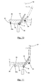
- Figs 7-9 show the hinge device H of Figs 3 and 4 applied to adjustably connect a seat 29 forming a first of said two articulated objects, and a centre column 30 of a carrier frame carrying the seat in a first embodiment of a working chair or a swivel chair according to the invention.
- the carrier frame further comprises a foot 31 provided at the bottom end of the centre column 30 and a back rest 32 connected to the seat 29, the back rest 32 forming a second of said two articulated objects.
- the tubular enclosure 1 of the hinge device H is connected to the centre column 30 by means of an arm 33.
- the arm 33 engages the tubular enclosure 1 on the splinings 3b, 5b to provide a stronger rotational lock of the arm 33 to the tubular enclosure 1.
- the tubular enclosure 1 of the hinge device H abuts on the central part of the seat 29 and, by means of arms 13, 14, is connected to the backward part of the seat 29.
- the user may thus shift his position forwards or backwards while at all times being supported by the spring force exerted on the seat. Further, the maximum angle between the seat 29 and the back rest 32 may be adjusted by rotating the handle 16 as described in the above such that the tilting back of the back rest 32 may be delimited or extended.
- preloading of the spring to fit users of different weights or with different preferences can be achieved by use of the preloading means 24, 25 and the abutment member 10 activated by the handle 17.
- Figs 10 and 11 show a second embodiment of a working chair according to the invention with a hinge device H according to Figs 1 and 2.
- the foot of the chair is not shown.
- the hinge device H is mounted in proximity of the centre column 30 and connected to a back seat 32 via two arms, of which only one arm 13 is shown, the arm 13 forming a first of said two articulated objects, and the not shown arm forming a third object equivalent to said first object.
- the arms are provided on each side of a seat 29 of the chair.
- a first joint 34 connects the seat 29 and the back rest 32.
- the arm 13 is connected to the back rest 32 at a point near or right beneath a horizontal centre line through the back ret 32.
- the hinge device is further connected via an arm 33, forming a second of said two articulated objects, and a second joint 35, which constitutes the fulcrum for tilting the seat, near the front part of the seat 29 to the seat 29.
- the position of said fulcrum thus causes that the user's feet are not raised very much when the user leans backwards.
- Fig. 10 shows the chair in the unlocked position of the locking means 18, 19 of the hinge device H as described in the above.
- This provides a dynamic adjustment of the seat and back rest allowing the user to dynamically change his seating position between an upward position and a backward position, the difference between these being about 25° as shown.
- the seat 29 is also tilted backwards along with the back rest 32, albeit with a smaller angle of about 6.8°.
- preferred seating positions involve a larger angle of the back rest 32 than of the seat 29.
- power transmission may be varied by increasing the diameters of the threaded rods 2, 4 and the threaded tubes 3, 5 allowing for a longer spring deformation of the spring element.
- the length of the spring member 7 and the tubular enclosure may be varied to a high degree to correspond to different designs of the chair.
- the position of the hinge device H in the plane of the drawing may also be varied in order to change the geometrical relationship between the angle of the seat 29 and the angle of the back rest 32. If, as an example, the hinge device H is moved to the left in the figure, the back rest 32 will move relatively more than the seat 29.
- Fig. 11 the locking means 18, 19 of the hinge device H are in the locked position, and the joint 35 may slide up and down in rail 35a.
- This allows for a forward tilt of the seat 29 of about 5° in the embodiment shown, the corresponding movement angle of the back rest being about 2° as shown. Adjusting the position and rotation of rail 35a may vary the relationship between these angles.
- the angle adjustment of the back rest may, when adjusting the position of the joint 35, be entirely eliminated with proper arrangement of the rail 35a.
- Figs 12 and 13 show a third embodiment of a working chair according to the invention applying a hinge device H according to Figs 1 and 2.
- the third embodiment corresponds essentially to the second embodiment, the description of the second embodiment applying also to the third (Fig. 12 corresponding to Fig. 10, and Fig. 13 corresponding to Fig. 11).
- the arm 13 of the chair of the third embodiment has been given a backwardly curved shape in order to avoid disturbance of the user of the chair.
- the foot 31 of the chair is shown.
- a working chair described in the above may be provided with other adjustment means than the ones described, such as means for sliding the seat 29 forwards and backwards and means for independent adjustment of the seat 29 and the back rest 32.
- Such further adjustment means are well known to the person skilled in the art.
- a chair applying a hinge device H according to the invention may be constructed differently from the embodiments described in the above.
- the hinge device H may for example provide adjustment of the seat 29 alone, the back rest 32 being directly connected to the rod 30 of the chair, or the back rest 32 may be left out entirely.
- tubular enclosure 1 and the threaded rod 2 in the spring-loading of the seat 29 and the back rest 32 may be inverted; in the first embodiment (Figs 7-9), e.g., the tubular enclosure 1 may be connected to the seat 29 while the threaded rod 2 of the hinge device H is connected to the carrier frame instead. Also, more than one hinge device may be applied to a single chair.
- the hinge device H may comprise more than one, preferably two, hinge devices according to the invention.
- One or more hinge devices according to the invention may also, preferably positioned with its axis in a horizontal position, be applied to a luggage trunk of a car, preferably being positioned near the roof of the car, connecting a door of the trunk with a doorframe.
- electric motors are preferably provided for opening and closing the door. If the spring means of the hinge device are adjusted such that the door is "weightless", very small motors may be applied for this purpose.
- the motors may be placed inside or outside the hinge device.
- One or more hinge devices according to the invention may also, as a further example, be applied to a desk comprising a desktop and a carrier frame for carrying said desktop.
- a weightless adjustment of the spring means is very useful for providing a desktop, which may be readily raised and lowered by a user.
Priority Applications (2)
| Application Number | Priority Date | Filing Date | Title |
|---|---|---|---|
| EP06388011A EP1825780A1 (de) | 2006-02-24 | 2006-02-24 | Eine Scharniervorrichtung zur gelenkigen, federbelasteten Verbindung von zwei Gegenständen |
| PCT/DK2007/050025 WO2007095960A1 (en) | 2006-02-24 | 2007-02-26 | Hinge device for office chairs and an office chair |
Applications Claiming Priority (1)
| Application Number | Priority Date | Filing Date | Title |
|---|---|---|---|
| EP06388011A EP1825780A1 (de) | 2006-02-24 | 2006-02-24 | Eine Scharniervorrichtung zur gelenkigen, federbelasteten Verbindung von zwei Gegenständen |
Publications (1)
| Publication Number | Publication Date |
|---|---|
| EP1825780A1 true EP1825780A1 (de) | 2007-08-29 |
Family
ID=37057132
Family Applications (1)
| Application Number | Title | Priority Date | Filing Date |
|---|---|---|---|
| EP06388011A Withdrawn EP1825780A1 (de) | 2006-02-24 | 2006-02-24 | Eine Scharniervorrichtung zur gelenkigen, federbelasteten Verbindung von zwei Gegenständen |
Country Status (2)
| Country | Link |
|---|---|
| EP (1) | EP1825780A1 (de) |
| WO (1) | WO2007095960A1 (de) |
Cited By (3)
| Publication number | Priority date | Publication date | Assignee | Title |
|---|---|---|---|---|
| CN102247060A (zh) * | 2011-04-08 | 2011-11-23 | 谭干荣 | 一种新型结构椅座滑行驱动靠背倾斜的座椅 |
| CN102371044A (zh) * | 2011-11-17 | 2012-03-14 | 广西大学 | 一种户内外两用多功能健身椅 |
| IT202000031124A1 (it) * | 2020-12-16 | 2022-06-16 | Nuova Star Spa | Cerniera per coperchi di elettrodomestici |
Families Citing this family (4)
| Publication number | Priority date | Publication date | Assignee | Title |
|---|---|---|---|---|
| US11109683B2 (en) | 2019-02-21 | 2021-09-07 | Steelcase Inc. | Body support assembly and method for the use and assembly thereof |
| US11357329B2 (en) | 2019-12-13 | 2022-06-14 | Steelcase Inc. | Body support assembly and methods for the use and assembly thereof |
| WO2021178206A1 (en) | 2020-03-02 | 2021-09-10 | Steelcase Inc. | Body support assembly and methods for the use and assembly thereof |
| WO2022173799A1 (en) | 2021-02-10 | 2022-08-18 | Steelcase Inc. | Body support structure |
Citations (5)
| Publication number | Priority date | Publication date | Assignee | Title |
|---|---|---|---|---|
| GB2141171A (en) * | 1983-06-08 | 1984-12-12 | Chen Liang Erh | Automatic-return hinge |
| EP0460717A2 (de) * | 1987-09-30 | 1991-12-11 | Davis Furniture Industries Incorporated | Riegelvorrichtung fÀ¼r einen Bürostuhl |
| EP0582818A1 (de) * | 1992-07-16 | 1994-02-16 | Giroflex-Entwicklungs AG | Stuhl, insbesondere Bürostuhl |
| DE4424096A1 (de) * | 1994-07-12 | 1996-01-18 | Gotthard Bresch | Stuhl |
| US20050204508A1 (en) * | 2004-03-19 | 2005-09-22 | Fih Co., Ltd. | Hinge mechanism with single hand operation |
Family Cites Families (3)
| Publication number | Priority date | Publication date | Assignee | Title |
|---|---|---|---|---|
| US4818019A (en) * | 1987-02-09 | 1989-04-04 | Haworth, Inc. | Tilt control mechanism, particularly for knee-tilt chair |
| US5682644A (en) * | 1996-02-06 | 1997-11-04 | Component Hardware Group, Inc. | Hinge assembly |
| DE10126000A1 (de) * | 2001-05-18 | 2002-11-21 | Bock 1 Gmbh & Co | Synchronmechanik für die simultane Sitzflächen- und Rückenlehnen-Schwenkbewegung bei Bürostühlen |
-
2006
- 2006-02-24 EP EP06388011A patent/EP1825780A1/de not_active Withdrawn
-
2007
- 2007-02-26 WO PCT/DK2007/050025 patent/WO2007095960A1/en active Application Filing
Patent Citations (5)
| Publication number | Priority date | Publication date | Assignee | Title |
|---|---|---|---|---|
| GB2141171A (en) * | 1983-06-08 | 1984-12-12 | Chen Liang Erh | Automatic-return hinge |
| EP0460717A2 (de) * | 1987-09-30 | 1991-12-11 | Davis Furniture Industries Incorporated | Riegelvorrichtung fÀ¼r einen Bürostuhl |
| EP0582818A1 (de) * | 1992-07-16 | 1994-02-16 | Giroflex-Entwicklungs AG | Stuhl, insbesondere Bürostuhl |
| DE4424096A1 (de) * | 1994-07-12 | 1996-01-18 | Gotthard Bresch | Stuhl |
| US20050204508A1 (en) * | 2004-03-19 | 2005-09-22 | Fih Co., Ltd. | Hinge mechanism with single hand operation |
Cited By (3)
| Publication number | Priority date | Publication date | Assignee | Title |
|---|---|---|---|---|
| CN102247060A (zh) * | 2011-04-08 | 2011-11-23 | 谭干荣 | 一种新型结构椅座滑行驱动靠背倾斜的座椅 |
| CN102371044A (zh) * | 2011-11-17 | 2012-03-14 | 广西大学 | 一种户内外两用多功能健身椅 |
| IT202000031124A1 (it) * | 2020-12-16 | 2022-06-16 | Nuova Star Spa | Cerniera per coperchi di elettrodomestici |
Also Published As
| Publication number | Publication date |
|---|---|
| WO2007095960A1 (en) | 2007-08-30 |
Similar Documents
| Publication | Publication Date | Title |
|---|---|---|
| EP1825780A1 (de) | Eine Scharniervorrichtung zur gelenkigen, federbelasteten Verbindung von zwei Gegenständen | |
| US5931537A (en) | Adjustable chair arm assembly | |
| US5026117A (en) | Controller for seating and the like | |
| US9044094B2 (en) | Chair chassis | |
| CA2837363C (en) | Tilt mechanism for a chair and chair | |
| US20200196748A1 (en) | Hand-operated Worm Gear Height Adjustable Table | |
| CN102472071A (zh) | 门窗开闭系统和门窗开闭系统用承座 | |
| EP3616983B2 (de) | Anpassungsvorrichtung für eine kopfstütze | |
| JP5180964B2 (ja) | オフィス椅子の同期デバイス | |
| US20230075814A1 (en) | Adjustable desk chair | |
| WO2001097657A1 (de) | Ergonomischer büro-stuhl mit ausleger-fuss | |
| EP3262983B1 (de) | Sitzkippmechanismus mit zwei federn | |
| KR200471108Y1 (ko) | 좌판의 틸팅 강도 조절장치 | |
| CN201761398U (zh) | 一种座椅靠背的侧夹装置 | |
| CN104309499B (zh) | 一种车辆座椅倾斜机构及车辆座椅 | |
| US11647838B2 (en) | Tilting mounting apparatus | |
| WO1990015554A1 (en) | Linear actuator control system | |
| CN113080643B (zh) | 一种休闲椅 | |
| US11160377B2 (en) | Synchronous chair mechanism and chair having same | |
| KR102318357B1 (ko) | 등받이 틸팅 단계별 조절구조를 갖는 프레임 의자 | |
| CN219515751U (zh) | 腰靠调节机构及转椅 | |
| CN220735646U (zh) | 一种轮椅脚踏角度调节装置 | |
| JP3140382B2 (ja) | 椅 子 | |
| CN219021993U (zh) | 一种角度可调的扶手及具有其的轮椅 | |
| JPH0451621Y2 (de) |
Legal Events
| Date | Code | Title | Description |
|---|---|---|---|
| PUAI | Public reference made under article 153(3) epc to a published international application that has entered the european phase |
Free format text: ORIGINAL CODE: 0009012 |
|
| AK | Designated contracting states |
Kind code of ref document: A1 Designated state(s): AT BE BG CH CY CZ DE DK EE ES FI FR GB GR HU IE IS IT LI LT LU LV MC NL PL PT RO SE SI SK TR |
|
| AX | Request for extension of the european patent |
Extension state: AL BA HR MK YU |
|
| AKX | Designation fees paid | ||
| REG | Reference to a national code |
Ref country code: DE Ref legal event code: 8566 |
|
| STAA | Information on the status of an ep patent application or granted ep patent |
Free format text: STATUS: THE APPLICATION IS DEEMED TO BE WITHDRAWN |
|
| 18D | Application deemed to be withdrawn |
Effective date: 20080301 |