EP1825552B1 - Pile a combustible a oxyde solide equipee de collecteurs externes - Google Patents
Pile a combustible a oxyde solide equipee de collecteurs externes Download PDFInfo
- Publication number
- EP1825552B1 EP1825552B1 EP05803467A EP05803467A EP1825552B1 EP 1825552 B1 EP1825552 B1 EP 1825552B1 EP 05803467 A EP05803467 A EP 05803467A EP 05803467 A EP05803467 A EP 05803467A EP 1825552 B1 EP1825552 B1 EP 1825552B1
- Authority
- EP
- European Patent Office
- Prior art keywords
- manifold
- fuel cell
- plate
- extensions
- stack
- Prior art date
- Legal status (The legal status is an assumption and is not a legal conclusion. Google has not performed a legal analysis and makes no representation as to the accuracy of the status listed.)
- Expired - Lifetime
Links
Images
Classifications
-
- H—ELECTRICITY
- H01—ELECTRIC ELEMENTS
- H01M—PROCESSES OR MEANS, e.g. BATTERIES, FOR THE DIRECT CONVERSION OF CHEMICAL ENERGY INTO ELECTRICAL ENERGY
- H01M8/00—Fuel cells; Manufacture thereof
- H01M8/24—Grouping of fuel cells, e.g. stacking of fuel cells
- H01M8/2465—Details of groupings of fuel cells
- H01M8/2484—Details of groupings of fuel cells characterised by external manifolds
- H01M8/2485—Arrangements for sealing external manifolds; Arrangements for mounting external manifolds around a stack
-
- H—ELECTRICITY
- H01—ELECTRIC ELEMENTS
- H01M—PROCESSES OR MEANS, e.g. BATTERIES, FOR THE DIRECT CONVERSION OF CHEMICAL ENERGY INTO ELECTRICAL ENERGY
- H01M8/00—Fuel cells; Manufacture thereof
- H01M8/02—Details
- H01M8/0271—Sealing or supporting means around electrodes, matrices or membranes
-
- H—ELECTRICITY
- H01—ELECTRIC ELEMENTS
- H01M—PROCESSES OR MEANS, e.g. BATTERIES, FOR THE DIRECT CONVERSION OF CHEMICAL ENERGY INTO ELECTRICAL ENERGY
- H01M8/00—Fuel cells; Manufacture thereof
- H01M8/24—Grouping of fuel cells, e.g. stacking of fuel cells
- H01M8/241—Grouping of fuel cells, e.g. stacking of fuel cells with solid or matrix-supported electrolytes
- H01M8/2425—High-temperature cells with solid electrolytes
- H01M8/2432—Grouping of unit cells of planar configuration
-
- H—ELECTRICITY
- H01—ELECTRIC ELEMENTS
- H01M—PROCESSES OR MEANS, e.g. BATTERIES, FOR THE DIRECT CONVERSION OF CHEMICAL ENERGY INTO ELECTRICAL ENERGY
- H01M8/00—Fuel cells; Manufacture thereof
- H01M8/24—Grouping of fuel cells, e.g. stacking of fuel cells
- H01M8/2465—Details of groupings of fuel cells
- H01M8/2484—Details of groupings of fuel cells characterised by external manifolds
-
- H—ELECTRICITY
- H01—ELECTRIC ELEMENTS
- H01M—PROCESSES OR MEANS, e.g. BATTERIES, FOR THE DIRECT CONVERSION OF CHEMICAL ENERGY INTO ELECTRICAL ENERGY
- H01M8/00—Fuel cells; Manufacture thereof
- H01M8/02—Details
- H01M8/0271—Sealing or supporting means around electrodes, matrices or membranes
- H01M8/028—Sealing means characterised by their material
- H01M8/0282—Inorganic material
-
- Y—GENERAL TAGGING OF NEW TECHNOLOGICAL DEVELOPMENTS; GENERAL TAGGING OF CROSS-SECTIONAL TECHNOLOGIES SPANNING OVER SEVERAL SECTIONS OF THE IPC; TECHNICAL SUBJECTS COVERED BY FORMER USPC CROSS-REFERENCE ART COLLECTIONS [XRACs] AND DIGESTS
- Y02—TECHNOLOGIES OR APPLICATIONS FOR MITIGATION OR ADAPTATION AGAINST CLIMATE CHANGE
- Y02E—REDUCTION OF GREENHOUSE GAS [GHG] EMISSIONS, RELATED TO ENERGY GENERATION, TRANSMISSION OR DISTRIBUTION
- Y02E60/00—Enabling technologies; Technologies with a potential or indirect contribution to GHG emissions mitigation
- Y02E60/30—Hydrogen technology
- Y02E60/50—Fuel cells
Definitions
- the present invention relates to a solid oxide fuel cell with external manifolds.
- Conventional solid oxide fuel cell stacks are formed from stacked interconnect plates, also known as bipolar plates, fuel cells comprising membranes and electrodes, and seals.
- the interconnects and the fuel cells are typically planar and define air and fuel intake and exhaust openings. When stacked vertically, the openings define the intake and exhaust manifolds.
- the interconnect plates have internal passages on either side of a central barrier which directs air or fuel from its intake manifold, across the fuel cell electrode and into the exhaust manifold.
- the fuel cell is square and the fuel gas flows in a direction perpendicular to the direction of air flow across the cell.
- X-Y compression techniques include band clamps, and bolts with low thermal expansion but these techniques may suffer from material creep over time and eventually fail to hold the manifolds tightly to the stack.
- Document EP 130 2996 discloses a fuel cell stack which has manifold apertures sealed by gaskets, said gaskets having ribs that are pressed against the separator plates by clamping pressure of the stack to form gas sealing sections.
- the present invention relates to an externally manifolded fuel cell stack wherein each manifold is enclosed by a combination of vertical columns formed from extensions of the horizontal stack components and separate vertical manifold plates.
- the invention may comprise a fuel cell stack comprising a plurality of repeating horizontal fuel cell units and an external vertical fuel intake manifold, fuel exhaust manifold, oxidant intake manifold and oxidant exhaust manifold, each fuel cell unit comprising:
- each manifold plate is planar and bolted to or otherwise affixed to the exterior of the stack in a fluid tight manner.
- the anode manifold extensions, cathode manifold extensions and barrier plate manifold extensions define substantially vertical and opposing grooves and each manifold plate comprises vertical edges which fit within opposing grooves in a fluid tight manner. In operation, each manifold is pressurized so that the manifold plate is forced outward, sealing the manifold plate within the grooves.
- the invention may comprise a method of forming external manifolds on solid oxide fuel cell stack having four corners, comprising the steps of:
- the invention may comprise a planar solid oxide fuel cell stack comprising a plurality of vertically repeating fuel cell units comprising flow fields defined by sealing strips and planar barrier plates and vertical external manifolds, wherein each manifold is enclosed by a combination of:
- the present invention provides for a planar fuel cell stack with external manifolds.
- vertical or “vertically” shall refer to a direction perpendicular to the planar elements of the fuel cell stack. Accordingly, “horizontal” or “horizontally” shall refer to a direction parallel to the planar elements.
- Externally manifolded fuel cell stacks are distinguished from internally manifolded stacks.
- Internal manifold fuel cell stack designs incorporate holes or discrete openings through the interconnects that form vertical plenums that allow reactant gas distribution to and collection from the unit cells when stacked.
- internal manifolds are entirely enclosed by the vertically stacked elements which form the stack.
- External manifold fuel cell stacks do not typically have provisions built into the interconnect for gas distribution or collection in the vertical sense.
- External manifolds are typically attached to the stack once the stack of unit cells are assembled and provide a means to deliver and collect the reactant gases from the unit cells.
- the present invention relates to an externally manifolded fuel cell stack wherein each manifold is enclosed by a combination of vertical columns formed from extensions of the horizontal stack components and separate vertical manifold plates.
- the manifold plates cooperate or interface with the vertical columns to provide gas tight seals.
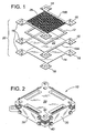
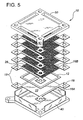
- a fuel cell stack (10) of the present invention comprises a repeating series of fuel cell units comprising a planar fuel cell (12), an interconnect (14) and sealing strips (16).
- the interconnects and sealing strips include horizontal extensions (18) which stack to form vertical columns (20) positioned on each corner of the stack (10). Therefore, the stack of the present invention preferably has a quadrilateral horizontal footprint and more preferably a square footprint.
- the stack itself comprises four vertical faces which are preferably, but not necessarily, substantially planar. The manifolds surround each stack face to supply and withdraw gas from the stack.
- Each fuel cell (12) comprises an anode side and a cathode side.
- An anode contact layer (22) directly contacts the anode and is positioned between opposing sealing strips (16A) which define an anode flow field between them.
- Fuel gases which enter the fuel intake manifold (24) flow between the opposing sealing strips, through the porous anode contact layer and exit to the fuel exhaust manifold (26) on the opposite stack face.
- a cathode contact layer (28) directly contacts the cathode and is positioned between opposing sealing strips (16B) which define the cathode flow field.
- the cathode sealing strips (16B) are positioned at right angles to the anode sealing strips (16A) if the fuel cell (12) is square or rectangular.
- Air or oxygen from the oxidant intake manifold (29) passes through the porous cathode contact layer (28), between the cathode sealing strips (16B) and passes into the oxidant exhaust manifold (32).
- each corner of the interconnects (14) and each end of each sealing strip ends in an extension (18) which extends beyond the fuel cells (12) and the flow fields.
- the extensions (18) stack on top of each to form a continuous vertical column (20).
- each corner of the stack comprises a vertical column (20) which forms one wall of the manifold on either side of the column.
- Each vertical column (20) may define a central opening through which a compression bolt (not shown) may pass.
- the compression bolt may form part of the means to compress the stack in the vertical dimension.
- the sealing strips (16) are preferably flexible and compressible. Suitable sealing strips may include mica or a ceramic material.
- a preferred seal material may include a ceramic felt or paper which is impregnated with small particles which may be metal, glass or ceramic.
- a preferred compressible seal material is described in Applicant's co-pending U.S. Patent Application No. 09/931,475 filed August 17, 2001 and titled "High Temperature Gas Seals.” Besides retaining gases within the flow fields, the seals serve to electrically insulate the stack and to provide a slip layer between adjacent fuel cell units to accommodate any differences in thermal expansion.
- the interconnects (14) may comprise simple planar barrier plates which are electrically conductive to act as current collectors.
- the area of the interconnect which faces the anode or cathode, as the case may be, may be rippled, corrugated, or otherwise textured, to facilitate or direct gas flow which maintaining electrical contact with the anode or cathode contact layer.
- Each of the anode and cathode contact layers are porous and electrically conductive.
- Suitable contact layer materials are well-known in the art and may include porous ceramic material, metallic foams such as nickel foam, or expanded metals.
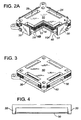
- Each manifold may then be enclosed with vertical manifold plates (30) as shown in Figure 2 .
- the manifold plates are preferably planar and may be bolted to upper and lower compression plates (40, 50) at the upper and lower ends of the stack.
- a seal material may be placed at the interface between the manifold plate and the columns.
- the attachment of the manifold plates (30) to the upper and lower compression plates maybe sufficient to provide a gas-tight seal along the edges of the manifold plate, particularly if a suitable sealing material is provided.
- outside gas pressure may be used to press the manifold plate against the stack.
- the stack may be contained within a hotbox (not shown) which is a substantially gas-tight enclosure.
- the hotbox may be pressurized such that the gas pressure inside the hotbox, which surrounds the stack, is higher than the manifold pressure inside the stack.
- a pressure differential may be about 5 psi.
- the attachment bolts may then be used primarily to locate the manifold plate against the stack, rather than provide any substantial compressive force.
- a vertical groove may be formed in each corner column (20) and the manifold plate fit within each groove.
- Horizontal grooves (not shown) in the top and bottom compression plates retain the top and bottom edges of the manifold plate.
- manifold gas pressure assists in sealing the manifold plate (30), eliminating or reducing the need to bolt or otherwise affixing the manifold plate to the stack.
- the manifold plate (30) floats within the grooves which retain each edge of the plate. Even a slight pressure differential will seal the mani fold plate (30) against the outer shoulder of each vertical and horizontal groove, thereby enclosing the manifold in a fluid tight manner.
- the term "floats" means the manifold plate is not affixed to any of the grooves by any mechanical or adhesive means.
- a thin seal or bedding element may be placed within each groove, or along the outer edges of the manifold plate, to help maintain fluid-tight contact between the manifold plate and each groove.
Landscapes
- Life Sciences & Earth Sciences (AREA)
- Engineering & Computer Science (AREA)
- Manufacturing & Machinery (AREA)
- Sustainable Development (AREA)
- Sustainable Energy (AREA)
- Chemical & Material Sciences (AREA)
- Chemical Kinetics & Catalysis (AREA)
- Electrochemistry (AREA)
- General Chemical & Material Sciences (AREA)
- Fuel Cell (AREA)
Claims (15)
- Bloc de piles à combustible (10) comprenant une pluralité d'unités de piles à combustible horizontales répétées et un collecteur d'admission de combustible (24) vertical externe, un collecteur d'évacuation de combustible (26), un collecteur d'admission d'oxydant (29) et un collecteur d'évacuation d'oxydant (32), chaque cellule de pile à combustible comprenant :(a) un élément de pile à combustible (12) comprenant une cathode, un électrolyte et une anode ;(b) une couche de champ d'écoulement cathodique comprenant un élément de contact cathodique poreux (28) et des bandes d'étanchéité opposées (16B) ayant des extensions de collecteur (18) s'étendant au-delà de l'élément de pile à combustible (12) ; et(c) une couche de champ d'écoulement anodique comprenant un élément de contact anodique poreux (22) et des bandes d'étanchéité opposées (16A) ayant des extensions de collecteur (18) s'étendant au-delà de l'élément de pile à combustible (12), dans lequel les bandes d'étanchéité anodiques (16A) sont essentiellement perpendiculaires aux bandes d'étanchéité cathodiques (16B), et dans lequel les extensions de collecteur anodiques (18) s'alignent verticalement avec les extensions de collecteur cathodiques (18) ;(d) une plaque barrière (14) comprenant quatre extensions de collecteur (18), chacune desquelles étant alignée verticalement avec les extensions de collecteur anodiques (18) et les extensions de collecteur cathodiques (18) ;où les extensions de collecteur cathodiques (18), les extensions de collecteur anodiques (18), les extensions de collecteur (18) de la plaque barrière de chaque unité de pile à combustible s'empilent verticalement pour former des colonnes (20) qui forment des parois latérales verticales des collecteurs et comprenant en outre une plaque de collecteur (30) qui renferme chacun des collecteurs en venant en butée contre deux colonnes adjacentes (20).
- Bloc de piles à combustible (10) de la revendication 1 dans lequel chaque plaque de collecteur (30) est boulonnée à l'extérieur du bloc (10), ou sinon fixée à ce dernier, de manière étanche aux fluides.
- Bloc de piles à combustible (10) de la revendication 1 dans lequel la plaque de collecteur (30) est quadrilatère et planaire.
- Bloc de piles à combustible (10) de la revendication 3 dans lequel les extensions de collecteur anodiques (18), les extensions de collecteur cathodiques (18) et les extensions de collecteur (18) de la plaque barrière définissent des rainures essentiellement verticales et opposées et où en outre chaque plaque de collecteur (30) comprend des bords verticaux qui s'ajustent dans des rainures opposées de manière étanche aux fluides.
- Bloc de piles à combustible (10) de la revendication 4 comprenant en outre une plaque de compression supérieure (40) et une plaque de compression inférieure (50), dans lequel la plaque de compression supérieure (40) définit une rainure pour recevoir un bord supérieur de la plaque de collecteur (30), et la plaque de compression inférieure (50) définit une rainure pour recevoir un bord inférieur de la plaque de collecteur (30).
- Bloc de piles à combustible (10) de la revendication 5 dans lequel la plaque de collecteur (30) flotte dans et est retenue par chacune des quatre rainures sur chacun des quatre bords de la plaque de collecteur (30).
- Bloc de piles à combustible (10) de la revendication 1 dans lequel chaque colonne (20) définit une ouverture verticale qui peut recevoir un boulon de compression.
- Bloc de piles à combustible (10) de la revendication 2 dans lequel la plaque de collecteur (30) est maintenue contre le bloc (10) au moins en partie par une pression de gaz externe.
- Procédé de formation de collecteurs externes sur un bloc de piles à combustible (10) à oxyde solide ayant quatre coins, comprenant les étapes consistant à :(a) former une colonne verticale (20) de matériau d'étanchéité et des extensions de plaque barrière (18) le long de chaque coin, dans lequel chaque couche de matériau d'étanchéité est une extension (18) d'une bande d'étanchéité anodique ou cathodique (16A, 16B) ; et(b) renfermer l'espace entre deux colonnes adjacentes (20) et le bloc (10) par une plaque de collecteur (30).
- Procédé de la revendication 9 dans lequel le bloc (10) comprend des plaques de compression inférieure et supérieure (50, 40), et comprenant en outre l'étape consistant à boulonner ou fixer chaque plaque de collecteur (30) aux plaques de compression inférieure et supérieure (50, 40), venant en butée contre au moins deux colonnes (20).
- Procédé de la revendication 9 dans lequel chaque colonne (20) définit deux rainures verticales, de sorte que deux colonnes adjacentes (20) définissent des rainures opposées, comprenant en outre l'étape consistant à insérer une plaque de collecteur (30) dans des rainures opposées pour renfermer le collecteur externe.
- Procédé de la revendication 9 dans lequel le bloc (10) comprend une plaque de compression supérieure (40) et une plaque de compression inférieure (50), où la plaque de compression supérieure (40) définit une rainure pour recevoir un bord supérieur de la plaque de collecteur (30), et la plaque de compression inférieure (0) définit une rainure pour recevoir un bord inférieur de la plaque de collecteur (30).
- Procédé de la revendication 10 comprenant en outre l'étape consistant à mettre sous pression une enceinte entourant le bloc (10) pour comprimer la plaque de collecteur (30) contre le bloc (10).
- Bloc de piles à combustible (10) de la revendication 1 dans lequel chaque unité de pile à combustible comprend des champs d'écoulement définis par des bandes d'étanchéité (16A, 16B) et des plaques barrière planaires (14) et des collecteurs externes verticaux, où chaque collecteur est renfermé par une combinaison :(a) de deux colonnes verticales (20) chacune formée à partir de couches alternées d'extensions de bandes d'étanchéité (18) et d'extensions de plaque barrière (18) ; et(b) d'une plaque de collecteur planaire verticale (30) s'étendant entre les deux colonnes verticales (20).
- Bloc de piles à combustible (10) de la revendication 14 dans lequel chaque plaque de collecteur (30) est essentiellement carrée ou rectangulaire et chaque colonne (20) définit une rainure essentiellement verticale pour recevoir un bord vertical de la plaque de collecteur (30).
Applications Claiming Priority (2)
| Application Number | Priority Date | Filing Date | Title |
|---|---|---|---|
| US10/904,692 US7291415B2 (en) | 2004-11-23 | 2004-11-23 | Solid oxide fuel cell with external manifolds |
| PCT/CA2005/001694 WO2006056044A1 (fr) | 2004-11-23 | 2005-11-04 | Pile a combustible a oxyde solide equipee de collecteurs externes |
Publications (3)
| Publication Number | Publication Date |
|---|---|
| EP1825552A1 EP1825552A1 (fr) | 2007-08-29 |
| EP1825552A4 EP1825552A4 (fr) | 2009-08-26 |
| EP1825552B1 true EP1825552B1 (fr) | 2010-08-11 |
Family
ID=36461293
Family Applications (1)
| Application Number | Title | Priority Date | Filing Date |
|---|---|---|---|
| EP05803467A Expired - Lifetime EP1825552B1 (fr) | 2004-11-23 | 2005-11-04 | Pile a combustible a oxyde solide equipee de collecteurs externes |
Country Status (8)
| Country | Link |
|---|---|
| US (1) | US7291415B2 (fr) |
| EP (1) | EP1825552B1 (fr) |
| JP (1) | JP5090921B2 (fr) |
| AT (1) | ATE477601T1 (fr) |
| AU (1) | AU2005309264B2 (fr) |
| CA (1) | CA2589520C (fr) |
| DE (1) | DE602005022925D1 (fr) |
| WO (1) | WO2006056044A1 (fr) |
Families Citing this family (16)
| Publication number | Priority date | Publication date | Assignee | Title |
|---|---|---|---|---|
| US7582378B2 (en) * | 2005-06-30 | 2009-09-01 | Freudenberg-Nok General Partnership | Fuel cell seal and plate features |
| US7740962B2 (en) | 2006-12-06 | 2010-06-22 | 3M Innovative Properties Company | Compact fuel cell stack with current shunt |
| US20080138667A1 (en) * | 2006-12-06 | 2008-06-12 | 3M Innovative Properties Company | Compact fuel cell stack with fastening member |
| US20080138670A1 (en) * | 2006-12-06 | 2008-06-12 | 3M Innovative Properties Company | Compact fuel cell stack with multiple plate arrangement |
| US20080138665A1 (en) * | 2006-12-06 | 2008-06-12 | 3M Innovative Properties Company | Compact fuel cell stack with gas ports |
| US20080138684A1 (en) * | 2006-12-06 | 2008-06-12 | 3M Innovative Properties Company | Compact fuel cell stack with uniform depth flow fields |
| US8288059B2 (en) * | 2006-12-15 | 2012-10-16 | 3M Innovative Properties Company | Processing methods and systems for assembling fuel cell perimeter gaskets |
| US8012284B2 (en) * | 2006-12-15 | 2011-09-06 | 3M Innovative Properties Company | Method and apparatus for fabricating roll good fuel cell subassemblies |
| US7732083B2 (en) * | 2006-12-15 | 2010-06-08 | 3M Innovative Properties Company | Gas diffusion layer incorporating a gasket |
| US8932738B2 (en) * | 2008-10-16 | 2015-01-13 | Institute Of Nuclear Energy Research | Fuel cell assembly structure |
| NL2002113C (nl) | 2008-10-20 | 2010-04-21 | Stichting Energie | Sofc-stack met gegolfde separatorplaat. |
| US9692079B2 (en) * | 2009-08-11 | 2017-06-27 | Delphi Technologies, Inc. | Laminated plate repeating fuel cell unit for an SOFC stack |
| CN102723507B (zh) * | 2012-05-22 | 2014-08-27 | 华中科技大学 | 一种外气道式平板型固体氧化物燃料电池堆及其装配方法 |
| US9812717B2 (en) | 2013-09-20 | 2017-11-07 | Delphi Technologies, Inc. | Fuel cell cassette with compliant seal |
| FR3045215B1 (fr) * | 2015-12-15 | 2023-03-03 | Commissariat Energie Atomique | Systeme de serrage autonome d'un empilement a oxydes solides de type soec/sofc a haute temperature |
| JP6890040B2 (ja) * | 2017-05-30 | 2021-06-18 | 森村Sofcテクノロジー株式会社 | 電気化学反応セルスタック |
Family Cites Families (8)
| Publication number | Priority date | Publication date | Assignee | Title |
|---|---|---|---|---|
| US4345009A (en) * | 1979-08-17 | 1982-08-17 | United Technologies Corporation | Fuel cell stack compressive loading system |
| US5514487A (en) * | 1994-12-27 | 1996-05-07 | Ballard Power Systems Inc. | Edge manifold assembly for an electrochemical fuel cell stack |
| GB9809372D0 (en) | 1998-05-02 | 1998-07-01 | British Gas Plc | Stack assembly primarily for an electrochemical fuel |
| US6461756B1 (en) * | 2000-08-11 | 2002-10-08 | Fuelcell Energy, Inc. | Retention system for fuel-cell stack manifolds |
| US20020022170A1 (en) * | 2000-08-18 | 2002-02-21 | Franklin Jerrold E. | Integrated and modular BSP/MEA/manifold plates for fuel cells |
| EP1302996A3 (fr) * | 2001-10-16 | 2006-04-19 | Matsushita Electric Industrial Co., Ltd. | Pile à combustible à électrolyte polymère |
| JP3608741B2 (ja) * | 2001-10-16 | 2005-01-12 | 松下電器産業株式会社 | 高分子電解質型燃料電池 |
| US20030091888A1 (en) * | 2001-11-15 | 2003-05-15 | Goggin Christopher M. | High-density, wireless fuel cell power unit |
-
2004
- 2004-11-23 US US10/904,692 patent/US7291415B2/en not_active Expired - Lifetime
-
2005
- 2005-11-04 AU AU2005309264A patent/AU2005309264B2/en not_active Ceased
- 2005-11-04 EP EP05803467A patent/EP1825552B1/fr not_active Expired - Lifetime
- 2005-11-04 AT AT05803467T patent/ATE477601T1/de not_active IP Right Cessation
- 2005-11-04 JP JP2007541596A patent/JP5090921B2/ja not_active Expired - Lifetime
- 2005-11-04 WO PCT/CA2005/001694 patent/WO2006056044A1/fr not_active Ceased
- 2005-11-04 DE DE602005022925T patent/DE602005022925D1/de not_active Expired - Lifetime
- 2005-11-04 CA CA2589520A patent/CA2589520C/fr not_active Expired - Lifetime
Also Published As
| Publication number | Publication date |
|---|---|
| US7291415B2 (en) | 2007-11-06 |
| ATE477601T1 (de) | 2010-08-15 |
| WO2006056044A1 (fr) | 2006-06-01 |
| JP5090921B2 (ja) | 2012-12-05 |
| US20060110647A1 (en) | 2006-05-25 |
| EP1825552A1 (fr) | 2007-08-29 |
| JP2008521178A (ja) | 2008-06-19 |
| EP1825552A4 (fr) | 2009-08-26 |
| CA2589520A1 (fr) | 2006-06-01 |
| AU2005309264B2 (en) | 2010-08-05 |
| AU2005309264A1 (en) | 2006-06-01 |
| CA2589520C (fr) | 2010-06-22 |
| DE602005022925D1 (de) | 2010-09-23 |
Similar Documents
| Publication | Publication Date | Title |
|---|---|---|
| EP1825552B1 (fr) | Pile a combustible a oxyde solide equipee de collecteurs externes | |
| CA2040344C (fr) | Ensemble de piles a combustible a raccordement et a reformage interne | |
| EP0405088B1 (fr) | Empilement de piles à combustible entièrement pourvu de canaux intérieurs | |
| AU2007203261B2 (en) | Compression assembly, solid oxide fuel cell stack, a process for compression of the solid oxide fuel cell stack and its use | |
| US4753857A (en) | Laminated fuel cell | |
| US5424144A (en) | One piece separator plate with insert ring step design | |
| US4963442A (en) | Internal manifolded molten carbonate fuel cell stack | |
| WO2013008655A1 (fr) | Empilement de piles sofc doté de moyens de force de compression adaptés en température | |
| US20040185321A1 (en) | Sofc with floating current collectors | |
| EP1932199B1 (fr) | Joint integre pour ensemble pile a combustible et assemblage de piles a combustible | |
| US5298342A (en) | Fuel cell crossover arrestor and pressure seal | |
| JP2002015751A (ja) | 燃料電池及びそのセパレータ | |
| US20040131915A1 (en) | Solid oxide fuel cell stack | |
| US20080014492A1 (en) | Compression assembly, solid oxide fuel cell stack, a process for compression of the solid oxide fuel cell stack and its use | |
| CN100492735C (zh) | 固体电解质燃料电池的电池单元 | |
| JP3995778B2 (ja) | 固体電解質型燃料電池および固体電解質型燃料電池のスタック構造 | |
| JP2569361Y2 (ja) | 燃料電池セパレータ | |
| JP6193780B2 (ja) | 燃料電池 | |
| JP2007207454A (ja) | 燃料電池スタック | |
| GB2617714A (en) | Gas diffusion method for use with fuel cell stack | |
| CA2453061A1 (fr) | Pile a combustible a oxyde solide munie de collecteurs externes | |
| JP2004363093A (ja) | 燃料電池およびその分解方法 | |
| IE61931B1 (en) | Fully internally manifolded fuel cell stack | |
| KR20080048639A (ko) | 골판지형 연료전지 | |
| JPH05307969A (ja) | 固体電解質型燃料電池 |
Legal Events
| Date | Code | Title | Description |
|---|---|---|---|
| PUAI | Public reference made under article 153(3) epc to a published international application that has entered the european phase |
Free format text: ORIGINAL CODE: 0009012 |
|
| 17P | Request for examination filed |
Effective date: 20070614 |
|
| AK | Designated contracting states |
Kind code of ref document: A1 Designated state(s): AT BE BG CH CY CZ DE DK EE ES FI FR GB GR HU IE IS IT LI LT LU LV MC NL PL PT RO SE SI SK TR |
|
| DAX | Request for extension of the european patent (deleted) | ||
| A4 | Supplementary search report drawn up and despatched |
Effective date: 20090723 |
|
| GRAP | Despatch of communication of intention to grant a patent |
Free format text: ORIGINAL CODE: EPIDOSNIGR1 |
|
| GRAS | Grant fee paid |
Free format text: ORIGINAL CODE: EPIDOSNIGR3 |
|
| GRAA | (expected) grant |
Free format text: ORIGINAL CODE: 0009210 |
|
| AK | Designated contracting states |
Kind code of ref document: B1 Designated state(s): AT BE BG CH CY CZ DE DK EE ES FI FR GB GR HU IE IS IT LI LT LU LV MC NL PL PT RO SE SI SK TR |
|
| REG | Reference to a national code |
Ref country code: GB Ref legal event code: FG4D |
|
| REG | Reference to a national code |
Ref country code: CH Ref legal event code: EP |
|
| REG | Reference to a national code |
Ref country code: IE Ref legal event code: FG4D |
|
| REF | Corresponds to: |
Ref document number: 602005022925 Country of ref document: DE Date of ref document: 20100923 Kind code of ref document: P |
|
| REG | Reference to a national code |
Ref country code: NL Ref legal event code: VDEP Effective date: 20100811 |
|
| LTIE | Lt: invalidation of european patent or patent extension |
Effective date: 20100811 |
|
| PG25 | Lapsed in a contracting state [announced via postgrant information from national office to epo] |
Ref country code: NL Free format text: LAPSE BECAUSE OF FAILURE TO SUBMIT A TRANSLATION OF THE DESCRIPTION OR TO PAY THE FEE WITHIN THE PRESCRIBED TIME-LIMIT Effective date: 20100811 Ref country code: LT Free format text: LAPSE BECAUSE OF FAILURE TO SUBMIT A TRANSLATION OF THE DESCRIPTION OR TO PAY THE FEE WITHIN THE PRESCRIBED TIME-LIMIT Effective date: 20100811 Ref country code: FI Free format text: LAPSE BECAUSE OF FAILURE TO SUBMIT A TRANSLATION OF THE DESCRIPTION OR TO PAY THE FEE WITHIN THE PRESCRIBED TIME-LIMIT Effective date: 20100811 Ref country code: AT Free format text: LAPSE BECAUSE OF FAILURE TO SUBMIT A TRANSLATION OF THE DESCRIPTION OR TO PAY THE FEE WITHIN THE PRESCRIBED TIME-LIMIT Effective date: 20100811 |
|
| PG25 | Lapsed in a contracting state [announced via postgrant information from national office to epo] |
Ref country code: SI Free format text: LAPSE BECAUSE OF FAILURE TO SUBMIT A TRANSLATION OF THE DESCRIPTION OR TO PAY THE FEE WITHIN THE PRESCRIBED TIME-LIMIT Effective date: 20100811 Ref country code: CY Free format text: LAPSE BECAUSE OF FAILURE TO SUBMIT A TRANSLATION OF THE DESCRIPTION OR TO PAY THE FEE WITHIN THE PRESCRIBED TIME-LIMIT Effective date: 20100811 Ref country code: PT Free format text: LAPSE BECAUSE OF FAILURE TO SUBMIT A TRANSLATION OF THE DESCRIPTION OR TO PAY THE FEE WITHIN THE PRESCRIBED TIME-LIMIT Effective date: 20101213 Ref country code: PL Free format text: LAPSE BECAUSE OF FAILURE TO SUBMIT A TRANSLATION OF THE DESCRIPTION OR TO PAY THE FEE WITHIN THE PRESCRIBED TIME-LIMIT Effective date: 20100811 Ref country code: IS Free format text: LAPSE BECAUSE OF FAILURE TO SUBMIT A TRANSLATION OF THE DESCRIPTION OR TO PAY THE FEE WITHIN THE PRESCRIBED TIME-LIMIT Effective date: 20101211 Ref country code: BG Free format text: LAPSE BECAUSE OF FAILURE TO SUBMIT A TRANSLATION OF THE DESCRIPTION OR TO PAY THE FEE WITHIN THE PRESCRIBED TIME-LIMIT Effective date: 20101111 |
|
| PG25 | Lapsed in a contracting state [announced via postgrant information from national office to epo] |
Ref country code: LV Free format text: LAPSE BECAUSE OF FAILURE TO SUBMIT A TRANSLATION OF THE DESCRIPTION OR TO PAY THE FEE WITHIN THE PRESCRIBED TIME-LIMIT Effective date: 20100811 Ref country code: GR Free format text: LAPSE BECAUSE OF FAILURE TO SUBMIT A TRANSLATION OF THE DESCRIPTION OR TO PAY THE FEE WITHIN THE PRESCRIBED TIME-LIMIT Effective date: 20101112 Ref country code: BE Free format text: LAPSE BECAUSE OF FAILURE TO SUBMIT A TRANSLATION OF THE DESCRIPTION OR TO PAY THE FEE WITHIN THE PRESCRIBED TIME-LIMIT Effective date: 20100811 Ref country code: SE Free format text: LAPSE BECAUSE OF FAILURE TO SUBMIT A TRANSLATION OF THE DESCRIPTION OR TO PAY THE FEE WITHIN THE PRESCRIBED TIME-LIMIT Effective date: 20100811 |
|
| PG25 | Lapsed in a contracting state [announced via postgrant information from national office to epo] |
Ref country code: DK Free format text: LAPSE BECAUSE OF FAILURE TO SUBMIT A TRANSLATION OF THE DESCRIPTION OR TO PAY THE FEE WITHIN THE PRESCRIBED TIME-LIMIT Effective date: 20100811 |
|
| PG25 | Lapsed in a contracting state [announced via postgrant information from national office to epo] |
Ref country code: EE Free format text: LAPSE BECAUSE OF FAILURE TO SUBMIT A TRANSLATION OF THE DESCRIPTION OR TO PAY THE FEE WITHIN THE PRESCRIBED TIME-LIMIT Effective date: 20100811 Ref country code: IT Free format text: LAPSE BECAUSE OF FAILURE TO SUBMIT A TRANSLATION OF THE DESCRIPTION OR TO PAY THE FEE WITHIN THE PRESCRIBED TIME-LIMIT Effective date: 20100811 Ref country code: RO Free format text: LAPSE BECAUSE OF FAILURE TO SUBMIT A TRANSLATION OF THE DESCRIPTION OR TO PAY THE FEE WITHIN THE PRESCRIBED TIME-LIMIT Effective date: 20100811 Ref country code: CZ Free format text: LAPSE BECAUSE OF FAILURE TO SUBMIT A TRANSLATION OF THE DESCRIPTION OR TO PAY THE FEE WITHIN THE PRESCRIBED TIME-LIMIT Effective date: 20100811 Ref country code: SK Free format text: LAPSE BECAUSE OF FAILURE TO SUBMIT A TRANSLATION OF THE DESCRIPTION OR TO PAY THE FEE WITHIN THE PRESCRIBED TIME-LIMIT Effective date: 20100811 |
|
| PLBE | No opposition filed within time limit |
Free format text: ORIGINAL CODE: 0009261 |
|
| STAA | Information on the status of an ep patent application or granted ep patent |
Free format text: STATUS: NO OPPOSITION FILED WITHIN TIME LIMIT |
|
| PG25 | Lapsed in a contracting state [announced via postgrant information from national office to epo] |
Ref country code: ES Free format text: LAPSE BECAUSE OF FAILURE TO SUBMIT A TRANSLATION OF THE DESCRIPTION OR TO PAY THE FEE WITHIN THE PRESCRIBED TIME-LIMIT Effective date: 20101122 Ref country code: MC Free format text: LAPSE BECAUSE OF NON-PAYMENT OF DUE FEES Effective date: 20101130 |
|
| REG | Reference to a national code |
Ref country code: CH Ref legal event code: PL |
|
| 26N | No opposition filed |
Effective date: 20110512 |
|
| PG25 | Lapsed in a contracting state [announced via postgrant information from national office to epo] |
Ref country code: LI Free format text: LAPSE BECAUSE OF NON-PAYMENT OF DUE FEES Effective date: 20101130 Ref country code: CH Free format text: LAPSE BECAUSE OF NON-PAYMENT OF DUE FEES Effective date: 20101130 |
|
| REG | Reference to a national code |
Ref country code: DE Ref legal event code: R097 Ref document number: 602005022925 Country of ref document: DE Effective date: 20110512 |
|
| PG25 | Lapsed in a contracting state [announced via postgrant information from national office to epo] |
Ref country code: IE Free format text: LAPSE BECAUSE OF NON-PAYMENT OF DUE FEES Effective date: 20101104 |
|
| PG25 | Lapsed in a contracting state [announced via postgrant information from national office to epo] |
Ref country code: LU Free format text: LAPSE BECAUSE OF NON-PAYMENT OF DUE FEES Effective date: 20101104 Ref country code: HU Free format text: LAPSE BECAUSE OF FAILURE TO SUBMIT A TRANSLATION OF THE DESCRIPTION OR TO PAY THE FEE WITHIN THE PRESCRIBED TIME-LIMIT Effective date: 20110212 |
|
| PG25 | Lapsed in a contracting state [announced via postgrant information from national office to epo] |
Ref country code: TR Free format text: LAPSE BECAUSE OF FAILURE TO SUBMIT A TRANSLATION OF THE DESCRIPTION OR TO PAY THE FEE WITHIN THE PRESCRIBED TIME-LIMIT Effective date: 20100811 |
|
| REG | Reference to a national code |
Ref country code: FR Ref legal event code: PLFP Year of fee payment: 11 |
|
| REG | Reference to a national code |
Ref country code: FR Ref legal event code: PLFP Year of fee payment: 12 |
|
| REG | Reference to a national code |
Ref country code: FR Ref legal event code: PLFP Year of fee payment: 13 |
|
| REG | Reference to a national code |
Ref country code: FR Ref legal event code: PLFP Year of fee payment: 14 |
|
| PGFP | Annual fee paid to national office [announced via postgrant information from national office to epo] |
Ref country code: GB Payment date: 20240912 Year of fee payment: 20 |
|
| PGFP | Annual fee paid to national office [announced via postgrant information from national office to epo] |
Ref country code: FR Payment date: 20240909 Year of fee payment: 20 |
|
| PGFP | Annual fee paid to national office [announced via postgrant information from national office to epo] |
Ref country code: DE Payment date: 20240910 Year of fee payment: 20 |
|
| REG | Reference to a national code |
Ref country code: DE Ref legal event code: R071 Ref document number: 602005022925 Country of ref document: DE |
|
| REG | Reference to a national code |
Ref country code: GB Ref legal event code: PE20 Expiry date: 20251103 |