EP1825333B1 - Separating plate, fixing device having the separating plate, method for producing the separating plate and image forming apparatus - Google Patents
Separating plate, fixing device having the separating plate, method for producing the separating plate and image forming apparatus Download PDFInfo
- Publication number
- EP1825333B1 EP1825333B1 EP05819707.0A EP05819707A EP1825333B1 EP 1825333 B1 EP1825333 B1 EP 1825333B1 EP 05819707 A EP05819707 A EP 05819707A EP 1825333 B1 EP1825333 B1 EP 1825333B1
- Authority
- EP
- European Patent Office
- Prior art keywords
- edge part
- separating plate
- fixing member
- fixing
- transfer paper
- Prior art date
- Legal status (The legal status is an assumption and is not a legal conclusion. Google has not performed a legal analysis and makes no representation as to the accuracy of the status listed.)
- Expired - Lifetime
Links
Images




Classifications
-
- G—PHYSICS
- G03—PHOTOGRAPHY; CINEMATOGRAPHY; ANALOGOUS TECHNIQUES USING WAVES OTHER THAN OPTICAL WAVES; ELECTROGRAPHY; HOLOGRAPHY
- G03G—ELECTROGRAPHY; ELECTROPHOTOGRAPHY; MAGNETOGRAPHY
- G03G15/00—Apparatus for electrographic processes using a charge pattern
- G03G15/20—Apparatus for electrographic processes using a charge pattern for fixing, e.g. by using heat
- G03G15/2003—Apparatus for electrographic processes using a charge pattern for fixing, e.g. by using heat using heat
- G03G15/2014—Apparatus for electrographic processes using a charge pattern for fixing, e.g. by using heat using heat using contact heat
- G03G15/2017—Structural details of the fixing unit in general, e.g. cooling means, heat shielding means
- G03G15/2028—Structural details of the fixing unit in general, e.g. cooling means, heat shielding means with means for handling the copy material in the fixing nip, e.g. introduction guides, stripping means
-
- G—PHYSICS
- G03—PHOTOGRAPHY; CINEMATOGRAPHY; ANALOGOUS TECHNIQUES USING WAVES OTHER THAN OPTICAL WAVES; ELECTROGRAPHY; HOLOGRAPHY
- G03G—ELECTROGRAPHY; ELECTROPHOTOGRAPHY; MAGNETOGRAPHY
- G03G2215/00—Apparatus for electrophotographic processes
- G03G2215/20—Details of the fixing device or porcess
- G03G2215/2003—Structural features of the fixing device
- G03G2215/2016—Heating belt
-
- G—PHYSICS
- G03—PHOTOGRAPHY; CINEMATOGRAPHY; ANALOGOUS TECHNIQUES USING WAVES OTHER THAN OPTICAL WAVES; ELECTROGRAPHY; HOLOGRAPHY
- G03G—ELECTROGRAPHY; ELECTROPHOTOGRAPHY; MAGNETOGRAPHY
- G03G2215/00—Apparatus for electrophotographic processes
- G03G2215/20—Details of the fixing device or porcess
- G03G2215/2003—Structural features of the fixing device
- G03G2215/2016—Heating belt
- G03G2215/2025—Heating belt the fixing nip having a rotating belt support member opposing a pressure member
- G03G2215/2032—Heating belt the fixing nip having a rotating belt support member opposing a pressure member the belt further entrained around additional rotating belt support members
Definitions
- the present invention relates to a separating plate used to separate a transfer paper from a fixing member in an electro-photographic type-image forming apparatus such as copying machines, printers, facsimiles or the like, a fixing device having the separating plate, a method for producing the separating plate and an image forming apparatus including the separating plate or the fixing device.
- An apparatus using an electro-photographic type for example, a laser printer has a rotatable photoconductive drum and forms an electrostatic latent image by exposing a photoconductive layer on the photoconductive drum by a laser beam from a laser scanning unit after the photoconductive layer on the photoconductive drum is charged uniformly.
- the laser printer is configured to form a toner image by developing the electrostatic latent image by a toner, transfer the toner image on a transfer paper, and then fix the toner image thermally by passing the transfer paper through a thermal fixing device.
- Such a conventional thermal fixing device uses a fixing roller including an anti-sticky layer such as fluorine resin to prevent an adhesive of a toner on an outer peripheral surface of a cored bar of a hollow cylinder made of, for example, aluminum, or the like.
- an anti-sticky layer such as fluorine resin
- the fixing roller is configured to dispose a heater such as a halogen lamp in the hollow cored bar along a rotational central axis of the roller and heat the fixing roller from an inside thereof by radiant heat of the heater.
- a heater such as a halogen lamp
- a fixing roller and a pressure roller contacting with the fixing roller and passing a transfer paper between the fixing and pressure rollers, while melting a toner adhered on the transfer paper by heat of the fixing roller, the toner is transferred on the transfer paper by pressuring.
- a separating pawl made of a heat-resistant resin such as polyimide, polyamide-imide, PPS (polyphenylene sulfide), or the like is provided to abut with the fixing roller in order to separate the transfer paper from the fixing roller or fixing belt.
- a fixing belt including a belt made of a metal or polyimide, an elastic layer of silicon rubber formed on the belt, and an adhesion-preventing layer of a fluorine resin formed on the elastic layer to prevent the adhesion of the toner has been used.
- Japanese Patent Laid-Open No. 2001-83832 discloses a peeling sheet for peeling a recording paper ejected from a nipping part between a fixing roller and a pressure roller from the fixing roller.
- the peeling sheet is formed from a thin metallic plate and includes an edge having a continuous curvature, and the edge is covered with a coating layer of a fluorine resin having mold-releasing property.
- Japanese Patent Laid-Open No. 2002-91222 discloses a peeling member including a supporting member, a peeling sheet connected with the supporting member by a sheet laser spot welding, and a fluorine resin sheet attached to a portion of the peeling sheet close to the fixing roller.
- Japanese Patent Laid-Open No. 2004-109636 discloses a separating pawl configured to abut with a fixing roller for contacting with a pressure roller.
- the separating pawl is disposed so that an angle at which a line connecting centers of the fixing and pressure rollers and a line connecting the center of the fixing roller and a contacting point of the separating pawl with the fixing roller are disposed is set at 40° or less.
- Japanese Patent Laid-Open No. 2003-122175 discloses that when a leading end of a transfer paper passes a separating member contacting with a fixing member, the separating member is moved.
- US 2003/0081970 A1 relates to a fixing unit.
- An electrophotographic image recording apparatus incorporates a fixing unit in which a toner image deposited on a print medium is fused by heat under pressure.
- the fixing unit includes a fixing member and a separator plate.
- the fixing member is in pressure contact with a pressure member.
- the separator plate that is disposed close to the fixing member and has a longitudinal portion extending in a direction transverse to a transport path of the print medium.
- the separator plate has a mid portion of the longitudinal portion.
- the mid portion has resiliency to extend away from the transport path and a guide member that pushes the mid portion of the separator plate to maintain the entire longitudinal portion flat so that mid portion is prevented from extending away from the transport path.
- US 6,678,497 B1 relates to a fixing device.
- the fixing device comprises a fixing member to contact a developer image forming surface of a recording medium, a pressure member to press contact a recording medium and convey a recording medium by clamping it together with the fixing member, and a non-contact separation member to separate a recording medium from the fixing member after passing the nip area formed between the fixing member and the pressure member, characterized in that r/L ⁇ 1 where r is a distance from an exit of the nip area to the separation edge of the separation member and L is the minimum value of the edge margin of a recording medium.
- JP 07-181826 A relates to a fixing device.
- An angle formed by a straight line connecting the centers of a fixing roller and a pressure roller and a straight line connecting the top end part of the separation guide and the center of the fixing roller is a separation angle.
- the separation angle of the part letting the edge part of a paper sheet pass is set larger than the separation angle of the part letting the central part of the paper pass by about 15°.
- the separation angle is set larger, the angle that the leading edge is wound on the fixing roller is made larger, so that the curling of the leading edge of the paper is increased.
- the separation angle is partially set larger to minimize influence on the curing of the leading edge of the paper.
- the separation conditions are made different between the edge and inside parts, to make the maintenance of conditions for designing and stable production easy and the curling of the leading edge smaller, even in a curvature separation system.
- JP 2003-316197 A relates to a fixing device and an image forming apparatus.
- a fixing device which has a fixing member and a pressure member and allows the recording material to pass a nip part between both members to fix a toner image on the recording material by actions of heat and pressure
- the surface hardness of the pressure member is made higher than that of the fixing member to form a projecting nip part
- a separation means for separating the recording material ejected from the projecting nip part from the surface of the pressure member is made to project between the surface of the pressure member and the front end of the recording material without coming into contact with them, and the front end of the separation means is placed on a line connecting the center of rotation of the pressure member and the front end of the recording material at the point when the rear end of a blank part on the front end side of the recording material reaches an exit of the projecting nip part.
- JP 2000-098791 A relates to a fixing device. Since a peeling aids member is arranged at a position where a distance from the exit of a nip part to a roll side end part is equal to or shorter than the feeding direction length of the non-image part of the top end part of the recording material, the non-image part of the recording material passes the exit of the nip part until the top end of the recording material is brought into contact with the roll side end part of the peeling aids member, and the top end of the recording material is brought into contact with the roll side end part of the peeling aids member.
- JP 2001-083832 A relates to a fixing device and peeling sheet used therefor.
- This fixing device is provided with a 1 st rotating body having a heat source and rotated in a specified direction and a 2nd rotating body which is rotated in contact with the body.
- the recording material carried with an unfixed image on its surface on the side in contact with the 1 st rotating body is conveyed to nip part where two rotating bodies are brought into contact with each other, and the recording material and the unfixed image are heated and pressurized to fix the unfixed image on the recording material.
- a peeling sheet for peeling of the recording material that is faced to a surface of the 1st rotating body is provided more downstream in the rotating direction of the 1 st rotating body than the nip part, the peeling sheet is provided with a continuous curvature part with no pointed part on its end edge on a side faced to the 1 st rotating body and at least the end edge of this continuous curvature part is coated with a releasing coating layer.
- a separating plate includes an edge part disposed close to the fixing member.
- the separating plate is disposed relative to the fixing member so that a sum of a thickness of the edge part of the separating plate and a gap formed between the edge part and the fixing member is lesser than a minimum floating amount of the transfer paper ejected from the nipping part.
- FIG.1 illustrates one embodiment of a fixing device according to the present invention.
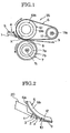
- the fixing device 55 includes a fixing roller 61, a heating roller 11, a fixing member, for example, a fixing belt 6 wound around the fixing roller 61 and the heating roller 11, a pressure member, for example, a pressure roller 7 for pressing the fixing belt 6 and a transfer paper 9 disposed on the fixing belt to the fixing roller 61, and a separating plate 1 for separating the transfer paper 9 from the fixing member or fixing belt 6.
- the fixing roller 61 and the pressure roller 7 hold the transfer paper 9 at a nipping part 8 formed between the fixing roller 61 and the pressure roller 7.
- the fixing roller 61 includes a cored bar 61a and an elastic layer 61b.
- the heating roller 11 has a heat source 11a such as a halogen heater or the like disposed therein.
- the fixing belt 6 includes a base member 6b and a mold releasing layer 6a (see FIG.2 ).
- the pressure roller 7 includes a cored bar 7a, an elastic layer 7b, and a heat source 7c disposed in the pressure roller 7.
- the fixing device 55 includes a separating plate 1 for peeling the transfer paper 9 closely fitted on the fixing belt 6 by the fixed toner on the transfer paper from the fixing belt when the fixed transfer paper 9 is ejected from the nipping part 8 formed by the fixing belt 6 and the pressure roller 7.
- the separating plate 1 has a structure shown in FIG.4E , for example.
- the separating plate 1 is integrally formed by a metallic plate such as iron, stainless steel and aluminum or the like by means of, for example, a rolling.
- the separating plate 1 has an elongate rectangular basic part 1a, an edge part 2 extending from one side edge of the basic part 1a, and supporting portions 22 provided to extend approximately perpendicularly to a surface of the basic part from opposite sides of the basic part.
- Mounting holes 22a passing through a mounting shaft 5 are provided in the supporting portions 22.
- the separating plate includes abutting parts 3 which are provided on areas where the transfer paper 9 does not pass, for example, opposite sides of the edge part 2 to contact with a surface of the fixing belt 6 (see FIG.4E ).
- the supporting parts 22 of the separating plate 1 are rotatably attached to a suitable mounting part (not shown) through the mounting shaft 5 so that the edge part 2 approaches to the fixing belt 6 and separates from the fixing belt 6.
- the separating plate 1 is rotated about the mounting shaft 5 so that the abutting parts 3 are contacted elastically with the surface of the fixing belt 6 by a biasing force of a spring 4 (see FIG.1 ).
- a thickness t (see FIG.2 ) of the edge part 2 is set to be a predetermined size, as described below.
- the transfer paper 9 is ejected from the nipping part 8 so that the leading end of the transfer paper 9 lifts from the surface of the fixing belt 6 slightly.
- FIG.3 illustrates a relationship of a length of blank space of the transfer paper 9 and a lift height of the leading end of the transfer paper 9.
- a relationship of a length of blank space at the leading end of each of three kinds of transfer papers 9 and a lift height 12 of the leading end of each transfer paper right after the transfer paper is ejected from the nipping part 8 is shown in FIG.3 .
- a tracing paper shown by a broken line a Ricoh 6200 type-paper shown by a solid line, and a postcard shown by a chain line are used.
- the lift height or amount is determined based on empirical rule from a kind of the transfer paper.
- a distance between the surface of the fixing belt 6 and the tip p of the edge part 2 of the separating plate 1 facing the fixing belt 6 is set to be lesser than a lift amount or lift height 12 of the transfer paper 9, which is obtained based on the kind and the blank space of the transfer paper 9 to be sent.
- the separating plate is disposed relative to the fixing member so that a sum of a thickness of the edge part 2 of the separating plate 1 and a gap formed between the edge part and the fixing member is lesser than a minimum lift height of the transfer paper 9 ejected from the nipping part 8.
- the gap 10 is set by suitably adjusting a thickness of the abutting pats 3 in accordance with the thickness of the edge part 2.
- the adjustment of thickness of the abutting parts can be achieved when a process for producing the separating plate is executed as described below.
- FIGs.4A to 4E illustrate one embodiment of a method for producing the separating plate according to the present invention
- FIG.5 illustrates one example of a rolling process in the producing method, as shown in FIGs.4A to 4E .
- the process for the producing method includes a slitting step as shown in FIG.4A , a rolling step as shown in FIG.4B , a step for forming an outer periphery of the separating plate as shown in FIG.4C , a punching step as shown in FIG.4D , and a bending step as shown in FIG.4E .
- the process for producing the separating plate first includes a step for forming a rectangular slit 21 close to a location of a blank 20 corresponding to the edge part 2 of the separating plate 1 (slitting step), as shown in FIG.4A .
- the blank 20 comprises a metallic plate made of iron, stainless steel, aluminum or the like.
- a rolling area 24 or location corresponding to the edge part 2 as shown in FIG.4A is rolled to form the edge part 2 and the abutting parts 3 (rolling step), as shown in FIG.4B .
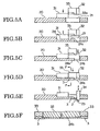
- the rolling area 24 is first rolled by a first press die 31 of a hydraulic pressing machine depending on a length and a thickness of the edge part 2, as shown in FIGs.5A and 5B .
- the hydraulic pressing machine includes the first pressing die 31, a second pressing die 32, a third pressing die 33, and a pressing die 34 for punching.
- the third pressing die 33 has a surface 33a for forming a semi-circular shape.
- the ability of the pressing machine is determined by a load for pressing.
- a load for pressing When the blank 20 of a metallic plate having the thickness of 16 mm is rolled into the edge part 2 having the thickness of 0.2 mm, a plurality of times of rolling steps are applied to the blank by use of a die in a pressing machine having the ability of 150 to 500 tons to form the edge part 2 having a predetermined thickness.
- the predetermined thickness of the edge part can be obtained with lesser times of rolling steps.
- a thickness of a rolled portion for forming the edge part, which is formed into the edge part 2 in an after step is rolled into a predetermined thickness by use of the second pressing die 32, thereafter, portions of the blank corresponding to the abutting parts 3 are rolled by use of the third pressing die 33, as shown in FIG.5D .
- the abutting parts 3 are set to have a thickness adding the gap 10 to the thickness of the edge part 2 by the rolling.
- abutting portions of the abutting parts with the surface of fixing belt 6 are configured to have curved surfaces, as shown in FIG.5D so that the abutting portions can be contacted with the surface of the moving fixing belt 6 without scratching on the surface of the fixing belt 6.
- the edge part 2 is formed by a pressing die 34 so as to punch out or remove an excess portion 23 of the edge portion 2 extended by the rolling from the edge part 2.
- a pressing die 34 it is possible to remove a burr tending to generate at the leading end of the edge part 2 by repeatedly upwardly and downwardly moving the punching die 34.
- the burr may be removed in an after step.
- an outer periphery of the supporting portions 22 for supporting the mounting shaft 5 and an engaging part 26 for supporting the spring 4 is punched out along a punching out line 25, and after punching out the outer periphery, then the supporting portions 22 are formed by approximately perpendicularly bending them through the bending step as shown in FIG.5E .
- the material and thickness of the blank 20 may be decided optionally based on a necessary stiffness depending on a moving speed and a passing width of the transfer paper 9. In particular, if the thickness of the edge part 2 is less than 0.1mm, a corrugation or crack may be generated at the tip of the edge part.
- the thickness of the edge part 2 exceeds 0.5 mm, there is a limitation that a blank space must be provided on the tracing paper as shown in FIG.3 . Therefore, a range of 0.1 to 0.5 mm as the thickness t of the edge part 2 is appropriate.
- a fluorine resin is covered on a surface of the separating plate 1 to prevent the attachment of a toner thereto right after fixation thereof.
- the separating plate 1 has no function for melting the toner and attaching the melted toner to the transfer paper 9 at the nipping part 8.
- a sufficient mold releasing force is not required for the separating plate 1 to achieve the function for preventing the adhesion of the toner, but it is preferable for the separating plate to form a more smoothly flat contacting surface to move smoothly the transfer paper 9 without generating orange peel or protrusions on a surface of the fluorine resin, which prevent the passing of the transfer paper.
- the mold releasing layer of the fixing belt or fixing roller which is made of a material including a fluorine resin of 50 to 70 weight percents is better than as in a material including a fluorine resin of 100 weight percents in mold-release property and heat-flowability.
- a primer layer is not required for the separating plate 1 by adding polyimide or polyamide-imide having an increased adhesiveness to the blank 20 to the material and a smoothly flat surface can be obtained for the separating plate 1.
- fluorine resin for the fluorine resin, PTFE (polytetrafluoroethylene), PFA (tetrafluoroethylene-perjluoroalkylvinylether-copolymer), FEP(tetraflu oroethylene-hexafluoroethylene-copolymer) or the like are listed as typical materials, while the fluorine resin has a high cohesive force and an insufficient dispersibility, therefore it requires a binder and occurs a spherical crystal when it is sintered, and hence has no a smooth surface.
- a fluorine resin layer is covered on the fixing roller, a finishing process such as a polishing or the like is required.
- a finishing process such as a polishing or the like is required.
- the coating of the fluorine resin is also formed on a surface where the transfer paper 9 passes.
- the surface where the transfer paper 9 passes means an outer corner portion or the tip p of the edge part 2, with which the transfer paper 9 ejected from the nipping part 8 contacts.
- a coating is formed on each of the curved surfaces of the abutting parts 3. That is to say, in the separating plate 1, the portions contacting with the fixing belt 6 and the transfer paper 9 are coated.
- the edge part 2 is processed by rolling, thereafter the abutting parts 3 are processed by rolling, the edge part 2 and the abutting parts 3 may be simultaneously roll-processed by a fourth pressing die 35 which is configured by integrating the second and third pressing dies 32 and 33 as shown in FIG.5 (see FIG.6 ).
- the edge part and the abutting parts can also be simultaneously processed by use of the fourth pressing die 35, similarly to the above-mentioned process.
- the edge part 2 may be processed by rolling.
- a hot dip galvanized steel plate (SGCD 1) having the thickness of 1.6mm and the size of 400mm by 200mm as the material of the separating plate 1 is first prepared.
- a rectangular slit 21 having the width of 5 mm is provided close to one side of the rolling area or location 24 corresponding to the edge part 2 in the steel plate by use of the high-flex press-NS2300tons made by Ida Engineering Co, Ltd, as shown in FIGs.4A and 5A .
- One portion of the location 24 throughout the width of about 3 mm from one edge of the slit 21 is then rolled to form the abutting parts 3 having the thickness of about 0.35mm (see FIGs.4B, 4C and 5B ).
- an area of the location 24 other than the abutting parts 3 is further rolled to form the edge part 2 having the thickness of 0.2 mm (see FIGs.4B, 4C , 5C and 5D ), and further the excess portion 23 of the edge part 2 is removed (see FIG.5E ), thereby the edge part 2 having the abutting parts 3 is completed.
- a fluorine-resinous paint including in solid content proportion, 60 weight percents of PTFE resin, 35 weight percents of polyimide resin, and 5 weight percents of a carbon black as an additive is sprayed on all surfaces of the separating plate where the transfer paper 9 passes, and the rolled part including the edge part 2 and the abutting parts 3 by a spray painting, after it is dried at 150°C, the separating plate is kept in an ambience of 360°C for 20 minutes, thereby a coating of fluorine resin is completed by such a baking.
- the separating plate 1 produced as the mentioned above was installed on a fixing unit in a color printer "IPSIO8000" made by Ricoh Co, Ltd, instead of a separating pawl (comparative example 1) which is mounted on the fixing unit and made of polyimide resin, and a test passing transfer papers was executed.
- the abutting parts 3 of the separating plate 1 were abutted with the both side areas of the fixing belt 6 where the transfer papers do not pass by pivoting the mounting shaft 5 having a diameter of 6mm on both side plates of the fixing unit and by providing the spring 4 while setting a force similar to the presently set contacting load 0.25 N of the conventional separating pawl.
- the thickness of the edge part 2 of the separating plate 1 was set to be 0.2 to 0.23 mm, and the gap was set to be 0.13 to 0.16 mm.
- a hot dip galvanized steel plate having the thickness of 1.6mm is first connected to a similar hot dip galvanized steel plate having the thickness of 0.2 mm by a laser spot welding, thereafter, a silicon system-primer agent is then sprayed to the connected member, after it is dried at 150°C, a fluorine resin tape is attached to a leading end of the edge part 2 to surround the leading end from a surface facing the transfer paper to the opposite back surface.
- the separating plate produced in this way is mounted on the fixing unit similarly as in the above, and a test for passing transfer papers was executed.
- the abutting parts 3 and the edge part 2 are formed by the rolling process to have a step between the abutting parts and the edge part.
- the leading ends of the abutting parts 3 may be provided by bending them to contact with the fixing belt 6 tangentially, as shown in FIG.7A or turning over the leading ends to face the fixing belt 6 or inwardly, as shown in FIG.7B , thereby the step between the edge part 2 and the abutting parts 3 is formed.
- the shape of the abutting parts may be selected optionally depending on a curvature of the fixing belt 6, a setting position of the separating plate 1, and a speed at which the transfer paper 9 is ejected.
- FIG.8 illustrates a full color laser printer which is a color image forming apparatus to which the fixing device according to the present invention is applied.
- the above-mentioned color laser printer has a structure in which upwardly and downwardly disposed paper feeders 42 are disposed downwardly of a main body 41 and an image forming part 43 is disposed above the feeders 42.
- a sheet-shaped medium any of a standard paper used for a usual copy or the like, and a special paper having a heat capacity greater than that of the standard paper and including an OHP sheet, a 90 K paper such as a card and a post card, a thick paper of basis weight, about 100g/m2 or more, and an envelope or the like.
- a transfer belt device which is disposed obliquely so that a feeding portion thereof is downwardly disposed and an ejecting portion thereof is upwardly disposed.
- the transfer belt device has an endless transfer belt 52 which is wound around a plurality of rollers 51, in the illustrated embodiment, four rollers 51 and rotated by driving one roller 51 by means of a drive source (not shown).
- a photoconductor 45 as an image carrier is provided on each of the image forming units 44M, 44C, 44Y and 44BK.
- the photoconductor 45 is configured to be rotated clockwise as viewed in FIG.8 by a drive device (not shown).
- a charging roller 46 as a charging device, a light writing section configured to achieve the writing of a laser beam by a light writing device 48, a developing device 50, and a cleaning device 49 are provided in a periphery of the photoconductor 45.
- Each of the developing devices 50 comprises a two ingredient developing device to which a toner is supplied by a toner supplying device which will be described below in accordance with a consumed amount of toner.
- a light image developed by a magenta toner is written on the photoconductor 45 charged by the charging roller 46 by means of the light writing device 48 which illuminates a laser beam to a polygon-miller 48a driving an LD (laser diode) (not shown) and guides light reflected on the polygon-miller through a cylindrical lens or the like to the photoconductor 45.
- an electrostatic latent image based on image data sent by a host machine such as a personal computer or the like is formed on the photoconductor 45 and the latent image becomes a visible image by the toner in the developing device 50.
- each of sheet-shaped media designated as transfer papers is supplied from each of the paper feeders 42, the supplied sheet-shaped medium is abutted once with a resist roller 53 provided at an upper stream in a direction of movement of the transfer belt 52, thereafter, it is supplied on the transfer belt 52 so as to synchronize with the visible image, and reaches a transfer position facing the photoconductor 45 by the movement of the transfer belt 52.
- the visible image of the magenta toner is transferred on the sheet-shaped medium by operation of the transfer roller 54 disposed to face a back side of the transfer belt 52.
- the visible image of each toner even in each of the other image forming units 44C, 44Y, and 44BK is formed on a surface of the respective photoconductor 45, these visible images are overlapped and transferred every the time that the sheet-shaped medium transported by the transfer belt 52 reaches each transfer position.
- the full color image is overlapped and transferred on the sheet-shaped medium in a short time, similarly to a mono-color image.
- the sheet-shaped medium after the transfer is separated from the transfer belt 52 and fixed by a fixing device 55. After the fixing is completed, the sheet-shaped medium is ejected out of the image forming apparatus usually directly, while, the sheet-shaped medium is then turned over and ejected on an ejected tray 56 provided on an upper surface of the main body 41.
- the fixing device 55 shown in FIG.8 has a thermal belt type, it may be structured to have a heating roller type.
- a mixing ratio of the toner and a carrier in the apparatus is monitored, if the toner is insufficient, an insufficient amount of the toner is supplemented.
- the supplementation of toner is accomplished by supplying the toner contained in a toner container 47 or toner containing device disposed at a position remote from the developing devices 50, in this embodiment, in a right and above position as shown in FIG.8 to the developing devices 50 through the toner supplying device.
- One toner container 47 is illustrated in FIG.8 , but actually four toner containers are provided according to the four developing devices, three toner containers are omitted in FIG.8 .
- the present invention is not limited to the above-mentioned embodiments.
- the fluorine resin coating is used as the mold-releasing material, but a fluorine resin sheet may be attached to the separating plate.
- the transfer paper can be separated from the fixing member efficiently without requiring a complicated process or assembly and damaging the fixing member such as the fixing roller or fixing belt, and hence jam or the like of the fixing member and so on can be prevented, and life duration of the fixing member can be increased.
- the separating plate according to the present invention is applied to the image forming apparatus such as the printer or the like, without being limited to this, for example, the separating plate may be used as a scraper aligning powder.
Landscapes
- Physics & Mathematics (AREA)
- General Physics & Mathematics (AREA)
- Fixing For Electrophotography (AREA)
- Separation, Sorting, Adjustment, Or Bending Of Sheets To Be Conveyed (AREA)
Description
- The present invention relates to a separating plate used to separate a transfer paper from a fixing member in an electro-photographic type-image forming apparatus such as copying machines, printers, facsimiles or the like, a fixing device having the separating plate, a method for producing the separating plate and an image forming apparatus including the separating plate or the fixing device.
- An apparatus using an electro-photographic type, for example, a laser printer has a rotatable photoconductive drum and forms an electrostatic latent image by exposing a photoconductive layer on the photoconductive drum by a laser beam from a laser scanning unit after the photoconductive layer on the photoconductive drum is charged uniformly.
- In addition, the laser printer is configured to form a toner image by developing the electrostatic latent image by a toner, transfer the toner image on a transfer paper, and then fix the toner image thermally by passing the transfer paper through a thermal fixing device.
- Such a conventional thermal fixing device uses a fixing roller including an anti-sticky layer such as fluorine resin to prevent an adhesive of a toner on an outer peripheral surface of a cored bar of a hollow cylinder made of, for example, aluminum, or the like.
- The fixing roller is configured to dispose a heater such as a halogen lamp in the hollow cored bar along a rotational central axis of the roller and heat the fixing roller from an inside thereof by radiant heat of the heater.
- Furthermore, by providing a fixing roller and a pressure roller contacting with the fixing roller and passing a transfer paper between the fixing and pressure rollers, while melting a toner adhered on the transfer paper by heat of the fixing roller, the toner is transferred on the transfer paper by pressuring. At this time, because the transfer paper is ejected in such a manner that the toner melts and fits closely to the fixing roller, a separating pawl made of a heat-resistant resin such as polyimide, polyamide-imide, PPS (polyphenylene sulfide), or the like is provided to abut with the fixing roller in order to separate the transfer paper from the fixing roller or fixing belt.
- In recent, with colorization of images, as a method of fixing a transfer paper in which several colored toners are laminated, a fixing belt including a belt made of a metal or polyimide, an elastic layer of silicon rubber formed on the belt, and an adhesion-preventing layer of a fluorine resin formed on the elastic layer to prevent the adhesion of the toner has been used.
- In a fixing belt or fixing roller using a color toner, when the separating pawl is abutted with the elastic layer, the separating pawl bites in the elastic layer there is a problem that the elastic layer, separating pawl or the like is damaged. Therefore, a peeling sheet pr separating plate which does not contact with the elastic layer has been used.
- Conventionally known are various technologies for separating a transfer paper from a fixing member such as a fixing roller or fixing belt.
- Japanese Patent Laid-Open No.
2001-83832 - Japanese Patent Laid-Open No.
2002-91222 - Japanese Patent Laid-Open No.
2004-109636 - In addition, Japanese Patent Laid-Open No.
2003-122175 - However, in the peeling sheet disclosed in Japanese Patent Laid-Open No.
2001-83832 - Also, in Japanese Patent Laid-Open No.
2002-91222 - Moreover, in Japanese Patent Laid-Open No.
2004-109636 - Furthermore, in Japanese Patent Laid-Open No.
2003-122175 -
US 2003/0081970 A1 relates to a fixing unit. An electrophotographic image recording apparatus incorporates a fixing unit in which a toner image deposited on a print medium is fused by heat under pressure. The fixing unit includes a fixing member and a separator plate. The fixing member is in pressure contact with a pressure member. The separator plate that is disposed close to the fixing member and has a longitudinal portion extending in a direction transverse to a transport path of the print medium. The separator plate has a mid portion of the longitudinal portion. The mid portion has resiliency to extend away from the transport path and a guide member that pushes the mid portion of the separator plate to maintain the entire longitudinal portion flat so that mid portion is prevented from extending away from the transport path. -
US 6,678,497 B1 relates to a fixing device. The fixing device comprises a fixing member to contact a developer image forming surface of a recording medium, a pressure member to press contact a recording medium and convey a recording medium by clamping it together with the fixing member, and a non-contact separation member to separate a recording medium from the fixing member after passing the nip area formed between the fixing member and the pressure member, characterized in that r/L≦1 where r is a distance from an exit of the nip area to the separation edge of the separation member and L is the minimum value of the edge margin of a recording medium. -
JP 07-181826 A -
JP 2003-316197 A -
JP 2000-098791 A -
JP 2001-083832 A - It is an object of the present invention to provide an improved and useful fixing device in which the above-mentioned problems are eliminated.
- In order to achieve the above-mentioned object, there is provided a fixing device according to
claim 1 and a method according toclaim 9. - Advantageous embodiments are defined by the dependent claims.
- Advantageously, a separating plate includes an edge part disposed close to the fixing member.
- The separating plate is disposed relative to the fixing member so that a sum of a thickness of the edge part of the separating plate and a gap formed between the edge part and the fixing member is lesser than a minimum floating amount of the transfer paper ejected from the nipping part.
-
-
FIG.1 is a side elevational view showing one embodiment of a fixing device according to the present invention. -
FIG.2 is an enlarged view of an X portion inFIG.1 . -
FIG.3 is a graph showing a relationship of a length of blank space of a transfer paper and a lift height of a leading end of the transfer paper. -
FIGs.4A to 4E are process views showing a method for producing a separating plate in the fixing device according to the present invention. -
FIGs.5A to 5F are process views showing one example of a rolling process in the producing method shown inFIGs.4A to 4E . -
FIGs.6A to 6E are process views showing another example of the rolling process in the producing method shown inFIGs.4A to 4E . -
FIG.7A is a partial side elevational view showing a modified example of abutting parts. -
FIG.7B is a partial side elevational view showing a further modified example of the abutting parts. -
FIG.8 is a schematic structural view of an image forming apparatus according to the present invention. - Hereinafter, a best mode for carrying out the present invention will be explained based on some embodiments with reference to the accompanying drawings.
-
FIG.1 illustrates one embodiment of a fixing device according to the present invention. As shown inFIG.1 , the fixingdevice 55 includes a fixingroller 61, a heating roller 11, a fixing member, for example, a fixingbelt 6 wound around the fixingroller 61 and the heating roller 11, a pressure member, for example, apressure roller 7 for pressing the fixingbelt 6 and atransfer paper 9 disposed on the fixing belt to the fixingroller 61, and aseparating plate 1 for separating thetransfer paper 9 from the fixing member or fixingbelt 6. - The fixing
roller 61 and thepressure roller 7 hold thetransfer paper 9 at a nippingpart 8 formed between the fixingroller 61 and thepressure roller 7. - The fixing
roller 61 includes a cored bar 61a and anelastic layer 61b. The heating roller 11 has aheat source 11a such as a halogen heater or the like disposed therein. The fixingbelt 6 includes abase member 6b and amold releasing layer 6a (seeFIG.2 ). Thepressure roller 7 includes a cored bar 7a, an elastic layer 7b, and aheat source 7c disposed in thepressure roller 7. - The fixing
device 55 includes a separatingplate 1 for peeling thetransfer paper 9 closely fitted on the fixingbelt 6 by the fixed toner on the transfer paper from the fixing belt when the fixedtransfer paper 9 is ejected from the nippingpart 8 formed by the fixingbelt 6 and thepressure roller 7. - The separating
plate 1 has a structure shown inFIG.4E , for example. In this embodiment, the separatingplate 1 is integrally formed by a metallic plate such as iron, stainless steel and aluminum or the like by means of, for example, a rolling. The separatingplate 1 has an elongate rectangularbasic part 1a, anedge part 2 extending from one side edge of thebasic part 1a, and supportingportions 22 provided to extend approximately perpendicularly to a surface of the basic part from opposite sides of the basic part. - Mounting
holes 22a passing through a mountingshaft 5 are provided in the supportingportions 22. - The separating plate includes abutting
parts 3 which are provided on areas where thetransfer paper 9 does not pass, for example, opposite sides of theedge part 2 to contact with a surface of the fixing belt 6 (seeFIG.4E ). - The supporting
parts 22 of the separatingplate 1 are rotatably attached to a suitable mounting part (not shown) through the mountingshaft 5 so that theedge part 2 approaches to the fixingbelt 6 and separates from the fixingbelt 6. - The separating
plate 1 is rotated about the mountingshaft 5 so that the abuttingparts 3 are contacted elastically with the surface of the fixingbelt 6 by a biasing force of a spring 4 (seeFIG.1 ). - When the abutting
parts 3 of the separatingplate 1 contact with the fixing belt, a gap having a predetermined dimension is established between the leading end, in other words, a tip p of theedge part 2 and the surface of the fixing belt (seeFIG.2 ). A thickness t (seeFIG.2 ) of theedge part 2 is set to be a predetermined size, as described below. - As shown in
FIG.2 , thetransfer paper 9 is ejected from the nippingpart 8 so that the leading end of thetransfer paper 9 lifts from the surface of the fixingbelt 6 slightly. -
FIG.3 illustrates a relationship of a length of blank space of thetransfer paper 9 and a lift height of the leading end of thetransfer paper 9. A relationship of a length of blank space at the leading end of each of three kinds oftransfer papers 9 and alift height 12 of the leading end of each transfer paper right after the transfer paper is ejected from the nippingpart 8 is shown inFIG.3 . - In this example, as the three kinds of transfer papers, a tracing paper shown by a broken line, a
Ricoh 6200 type-paper shown by a solid line, and a postcard shown by a chain line are used. - As is clear from
FIG.3 , a relatively thick paper tends to separate from the surface of the fixing belt, on the contrary, a thin paper is easy to closely fit to the surface of the fixing belt. This difference results from a hardness of a paper. - In this way, because the leading end of the
transfer paper 9 ejected from the nippingpart 8 lifts, if theedge part 2 of the separatingplate 1 gets enters a gap between a lifted part and the fixingbelt 6, it is possible to separate thetransfer paper 9 from the surface of the fixingbelt 6. - Here, as one example, the lift height or amount is determined based on empirical rule from a kind of the transfer paper.
- In order to achieve smoothly the movement of the
edge part 2 into the gap, a distance between the surface of the fixingbelt 6 and the tip p of theedge part 2 of the separatingplate 1 facing the fixingbelt 6 is set to be lesser than a lift amount orlift height 12 of thetransfer paper 9, which is obtained based on the kind and the blank space of thetransfer paper 9 to be sent. - In other words, the separating plate is disposed relative to the fixing member so that a sum of a thickness of the
edge part 2 of the separatingplate 1 and a gap formed between the edge part and the fixing member is lesser than a minimum lift height of thetransfer paper 9 ejected from the nippingpart 8. - The
gap 10 is set by suitably adjusting a thickness of the abuttingpats 3 in accordance with the thickness of theedge part 2. - The adjustment of thickness of the abutting parts can be achieved when a process for producing the separating plate is executed as described below.
-
FIGs.4A to 4E illustrate one embodiment of a method for producing the separating plate according to the present invention, andFIG.5 illustrates one example of a rolling process in the producing method, as shown inFIGs.4A to 4E . - The process for the producing method includes a slitting step as shown in
FIG.4A , a rolling step as shown inFIG.4B , a step for forming an outer periphery of the separating plate as shown inFIG.4C , a punching step as shown inFIG.4D , and a bending step as shown inFIG.4E . - More specifically, the process for producing the separating plate first includes a step for forming a
rectangular slit 21 close to a location of a blank 20 corresponding to theedge part 2 of the separating plate 1 (slitting step), as shown inFIG.4A . In one example, the blank 20 comprises a metallic plate made of iron, stainless steel, aluminum or the like. - Next, a rolling
area 24 or location corresponding to theedge part 2 as shown inFIG.4A is rolled to form theedge part 2 and the abutting parts 3 (rolling step), as shown inFIG.4B . - In the rolling step, the rolling
area 24 is first rolled by a first press die 31 of a hydraulic pressing machine depending on a length and a thickness of theedge part 2, as shown inFIGs.5A and 5B . - Meanwhile, the hydraulic pressing machine includes the first
pressing die 31, a secondpressing die 32, a thirdpressing die 33, and apressing die 34 for punching. The thirdpressing die 33 has asurface 33a for forming a semi-circular shape. - In general, the ability of the pressing machine is determined by a load for pressing. When the blank 20 of a metallic plate having the thickness of 16 mm is rolled into the
edge part 2 having the thickness of 0.2 mm, a plurality of times of rolling steps are applied to the blank by use of a die in a pressing machine having the ability of 150 to 500 tons to form theedge part 2 having a predetermined thickness. - If a pressure loading of the pressing machine is greater, the predetermined thickness of the edge part can be obtained with lesser times of rolling steps.
- Next, as shown in
FIG.5C , a thickness of a rolled portion for forming the edge part, which is formed into theedge part 2 in an after step is rolled into a predetermined thickness by use of the secondpressing die 32, thereafter, portions of the blank corresponding to the abuttingparts 3 are rolled by use of the thirdpressing die 33, as shown inFIG.5D . - At this time, the abutting
parts 3 are set to have a thickness adding thegap 10 to the thickness of theedge part 2 by the rolling. - In addition, abutting portions of the abutting parts with the surface of fixing
belt 6 are configured to have curved surfaces, as shown inFIG.5D so that the abutting portions can be contacted with the surface of the moving fixingbelt 6 without scratching on the surface of the fixingbelt 6. - Subsequently, as shown in
FIG.5E , theedge part 2 is formed by apressing die 34 so as to punch out or remove anexcess portion 23 of theedge portion 2 extended by the rolling from theedge part 2. In this formation, it is possible to remove a burr tending to generate at the leading end of theedge part 2 by repeatedly upwardly and downwardly moving the punching die 34. In addition, the burr may be removed in an after step. - Next, as shown in the outer peripheral processing step in
FIG.5C and the punching out step inFIG.5D , an outer periphery of the supportingportions 22 for supporting the mountingshaft 5 and anengaging part 26 for supporting thespring 4 is punched out along a punching outline 25, and after punching out the outer periphery, then the supportingportions 22 are formed by approximately perpendicularly bending them through the bending step as shown inFIG.5E . - The material and thickness of the blank 20 may be decided optionally based on a necessary stiffness depending on a moving speed and a passing width of the
transfer paper 9. In particular, if the thickness of theedge part 2 is less than 0.1mm, a corrugation or crack may be generated at the tip of the edge part. - If the thickness of the
edge part 2 exceeds 0.5 mm, there is a limitation that a blank space must be provided on the tracing paper as shown inFIG.3 . Therefore, a range of 0.1 to 0.5 mm as the thickness t of theedge part 2 is appropriate. - As mentioned above, after the separating
plate 1 is formed from the blank 20 by the pressing machine, a fluorine resin is covered on a surface of the separatingplate 1 to prevent the attachment of a toner thereto right after fixation thereof. - The separating
plate 1 has no function for melting the toner and attaching the melted toner to thetransfer paper 9 at the nippingpart 8. - A sufficient mold releasing force is not required for the separating
plate 1 to achieve the function for preventing the adhesion of the toner, but it is preferable for the separating plate to form a more smoothly flat contacting surface to move smoothly thetransfer paper 9 without generating orange peel or protrusions on a surface of the fluorine resin, which prevent the passing of the transfer paper. - As a result of reviewing the fluorine resin with a focus on the above, the mold releasing layer of the fixing belt or fixing roller, which is made of a material including a fluorine resin of 50 to 70 weight percents is better than as in a material including a fluorine resin of 100 weight percents in mold-release property and heat-flowability.
- In addition, a primer layer is not required for the separating
plate 1 by adding polyimide or polyamide-imide having an increased adhesiveness to the blank 20 to the material and a smoothly flat surface can be obtained for the separatingplate 1. - For the fluorine resin, PTFE (polytetrafluoroethylene), PFA (tetrafluoroethylene-perjluoroalkylvinylether-copolymer), FEP(tetraflu oroethylene-hexafluoroethylene-copolymer) or the like are listed as typical materials, while the fluorine resin has a high cohesive force and an insufficient dispersibility, therefore it requires a binder and occurs a spherical crystal when it is sintered, and hence has no a smooth surface.
- Generally, if a fluorine resin layer is covered on the fixing roller, a finishing process such as a polishing or the like is required. In view of the fact and the function of the separating
plate 1, it is possible to omit a primer or finishing process by suitably setting the mold releasing layer. - The coating of the fluorine resin is also formed on a surface where the
transfer paper 9 passes. The surface where thetransfer paper 9 passes means an outer corner portion or the tip p of theedge part 2, with which thetransfer paper 9 ejected from the nippingpart 8 contacts. Moreover, a coating is formed on each of the curved surfaces of the abuttingparts 3. That is to say, in the separatingplate 1, the portions contacting with the fixingbelt 6 and thetransfer paper 9 are coated. - In the rolling steps as shown in
FIGs.5A to 5F , although theedge part 2 is processed by rolling, thereafter the abuttingparts 3 are processed by rolling, theedge part 2 and the abuttingparts 3 may be simultaneously roll-processed by a fourthpressing die 35 which is configured by integrating the second and third pressing dies 32 and 33 as shown inFIG.5 (seeFIG.6 ). - In the rolling steps as shown in
FIGs.6A to 6E , the edge part and the abutting parts can also be simultaneously processed by use of the fourthpressing die 35, similarly to the above-mentioned process. - In addition, instead of the rolling process of the abutting
parts 3 after theedge part 2 is processed by rolling, after the abuttingparts 3 are processed by rolling, theedge part 2 may be processed by rolling. - Subsequently, a further detailed process for producing the separating
plate 1 is explained as follows. - A hot dip galvanized steel plate (SGCD 1) having the thickness of 1.6mm and the size of 400mm by 200mm as the material of the separating
plate 1 is first prepared. In the embodiment, arectangular slit 21 having the width of 5 mm is provided close to one side of the rolling area orlocation 24 corresponding to theedge part 2 in the steel plate by use of the high-flex press-NS2300tons made by Ida Engineering Co, Ltd, as shown inFIGs.4A and5A . - One portion of the
location 24 throughout the width of about 3 mm from one edge of theslit 21 is then rolled to form the abuttingparts 3 having the thickness of about 0.35mm (seeFIGs.4B, 4C and5B ). - Next, an area of the
location 24 other than the abuttingparts 3 is further rolled to form theedge part 2 having the thickness of 0.2 mm (seeFIGs.4B, 4C ,5C and 5D ), and further theexcess portion 23 of theedge part 2 is removed (seeFIG.5E ), thereby theedge part 2 having the abuttingparts 3 is completed. - Subsequently, the outer periphery of the supporting
portions 22 and theengaging part 26 is punched out along the punching out line 25 (seeFIGs.4C and 4D ), and then the supportingportions 22 are bent perpendicularly (seeFIG.4E ), thereby the separatingplate 1 is completed as shown inFIG.4E . - Next, a fluorine-resinous paint including in solid content proportion, 60 weight percents of PTFE resin, 35 weight percents of polyimide resin, and 5 weight percents of a carbon black as an additive is sprayed on all surfaces of the separating plate where the
transfer paper 9 passes, and the rolled part including theedge part 2 and the abuttingparts 3 by a spray painting, after it is dried at 150°C, the separating plate is kept in an ambience of 360°C for 20 minutes, thereby a coating of fluorine resin is completed by such a baking. - The separating
plate 1 produced as the mentioned above was installed on a fixing unit in a color printer "IPSIO8000" made by Ricoh Co, Ltd, instead of a separating pawl (comparative example 1) which is mounted on the fixing unit and made of polyimide resin, and a test passing transfer papers was executed. - In the installation of the separating
plate 1, the abuttingparts 3 of the separatingplate 1 were abutted with the both side areas of the fixingbelt 6 where the transfer papers do not pass by pivoting the mountingshaft 5 having a diameter of 6mm on both side plates of the fixing unit and by providing thespring 4 while setting a force similar to the presently set contacting load 0.25 N of the conventional separating pawl. - The thickness of the
edge part 2 of the separatingplate 1 was set to be 0.2 to 0.23 mm, and the gap was set to be 0.13 to 0.16 mm. - Moreover, as a comparative example 2, similarly to the method for producing the supporting member disclosed in Japanese Patent Laid-Open
2002-91222 edge part 2 to surround the leading end from a surface facing the transfer paper to the opposite back surface. - The separating plate produced in this way is mounted on the fixing unit similarly as in the above, and a test for passing transfer papers was executed.
- The results of the test are shown in a table 1 which is incorporated herein. As is clear from the table 1, various kinds of
transfer papers 9 can be separated without generating abnormal images and life duration of the fixingbelt 6 can be increased by the structure of the separatingplate 1 as shown in the above-mentioned embodiments according to the present invention, compared with the conventional contact-type separating pawl.[Table 1] separating type kind of transfer paper initial feeding quality number of occurrence of jam time lapse-image quality after feeding of five tenthousand Ricoh 6200 type-papers durability of fixing belt Ricoh 6200 type transfer paper determination embodiment tracing paper no occurrence good no occurrence ○ three times about continuous feed of one-hundred papers per one time Ricoh 6200 type no occurrence three times about continuous feed of one-hundred papers per one time break of surface and removal of film of fixing belt in continuous feed of fifteen tenthousand papers post card no occurrence three times about continuous feed of fifty papers per one time comparative example 1 tracing paper no occurrence occurrence of abnormal image by friction of fixing belt by separating pawl occurrence × three times about continuous feed of one-hundred papers per one time Ricoh 6200 type no occurrence separating pawl type three times about continuous feed of one-hundred papers per one time break of surface of fixing belt by separating pawl in continuous feed of one hundred-thousand papers post card no occurrence three times about continuous feed of fifty papers per one time comparative example 2 tracing paper no occurrence occurrence no occurrence × three times about continuous feed of one-hundred papers per one time Ricoh 6200 type no occurrence type of welding leading end to supporting member three times about continuous feed of one-hundred papers per one time lifting of fluorine resin sheet occurrence of abnormal image by fixing of toner at lifting part break of surface and removal of film of fixing belt in continuous feed of fifteen tenthousand papers post card no occurrence three times about continuous feed of fifty papers per one time - In the above-mentioned embodiments, the abutting
parts 3 and theedge part 2 are formed by the rolling process to have a step between the abutting parts and the edge part. However, the leading ends of the abuttingparts 3 may be provided by bending them to contact with the fixingbelt 6 tangentially, as shown inFIG.7A or turning over the leading ends to face the fixingbelt 6 or inwardly, as shown inFIG.7B , thereby the step between theedge part 2 and the abuttingparts 3 is formed. - The shape of the abutting parts may be selected optionally depending on a curvature of the fixing
belt 6, a setting position of the separatingplate 1, and a speed at which thetransfer paper 9 is ejected. -
FIG.8 illustrates a full color laser printer which is a color image forming apparatus to which the fixing device according to the present invention is applied. - The above-mentioned color laser printer has a structure in which upwardly and downwardly disposed
paper feeders 42 are disposed downwardly of amain body 41 and animage forming part 43 is disposed above thefeeders 42. In the printer, it is possible to use as a sheet-shaped medium any of a standard paper used for a usual copy or the like, and a special paper having a heat capacity greater than that of the standard paper and including an OHP sheet, a 90 K paper such as a card and a post card, a thick paper of basis weight, about 100g/m2 or more, and an envelope or the like. - In addition, provided in the
image forming part 43 is a transfer belt device which is disposed obliquely so that a feeding portion thereof is downwardly disposed and an ejecting portion thereof is upwardly disposed. The transfer belt device has anendless transfer belt 52 which is wound around a plurality ofrollers 51, in the illustrated embodiment, fourrollers 51 and rotated by driving oneroller 51 by means of a drive source (not shown). - Four
image forming units transfer belt 52 in sequence from below. - A
photoconductor 45 as an image carrier is provided on each of theimage forming units - The
photoconductor 45 is configured to be rotated clockwise as viewed inFIG.8 by a drive device (not shown). A chargingroller 46 as a charging device, a light writing section configured to achieve the writing of a laser beam by alight writing device 48, a developingdevice 50, and acleaning device 49 are provided in a periphery of thephotoconductor 45. - Each of the developing
devices 50 comprises a two ingredient developing device to which a toner is supplied by a toner supplying device which will be described below in accordance with a consumed amount of toner. - Next, an operation foe carrying out a full color print by the color printer having the structure as mentioned above is explained based on the
image forming unit 44 M for magenta. - A light image developed by a magenta toner is written on the
photoconductor 45 charged by the chargingroller 46 by means of thelight writing device 48 which illuminates a laser beam to a polygon-miller 48a driving an LD (laser diode) (not shown) and guides light reflected on the polygon-miller through a cylindrical lens or the like to thephotoconductor 45. By the light writing, an electrostatic latent image based on image data sent by a host machine such as a personal computer or the like is formed on thephotoconductor 45 and the latent image becomes a visible image by the toner in the developingdevice 50. - On the other hand, each of sheet-shaped media designated as transfer papers is supplied from each of the
paper feeders 42, the supplied sheet-shaped medium is abutted once with a resistroller 53 provided at an upper stream in a direction of movement of thetransfer belt 52, thereafter, it is supplied on thetransfer belt 52 so as to synchronize with the visible image, and reaches a transfer position facing thephotoconductor 45 by the movement of thetransfer belt 52. - In this transfer position, the visible image of the magenta toner is transferred on the sheet-shaped medium by operation of the
transfer roller 54 disposed to face a back side of thetransfer belt 52. - Similarly to the above, the visible image of each toner even in each of the other
image forming units respective photoconductor 45, these visible images are overlapped and transferred every the time that the sheet-shaped medium transported by thetransfer belt 52 reaches each transfer position. - Therefore, in the color printer, the full color image is overlapped and transferred on the sheet-shaped medium in a short time, similarly to a mono-color image. The sheet-shaped medium after the transfer is separated from the
transfer belt 52 and fixed by a fixingdevice 55. After the fixing is completed, the sheet-shaped medium is ejected out of the image forming apparatus usually directly, while, the sheet-shaped medium is then turned over and ejected on an ejectedtray 56 provided on an upper surface of themain body 41. - Meanwhile, although the fixing
device 55 shown inFIG.8 has a thermal belt type, it may be structured to have a heating roller type. - In each of the above-mentioned developing
devices 50, a mixing ratio of the toner and a carrier in the apparatus is monitored, if the toner is insufficient, an insufficient amount of the toner is supplemented. - The supplementation of toner is accomplished by supplying the toner contained in a
toner container 47 or toner containing device disposed at a position remote from the developingdevices 50, in this embodiment, in a right and above position as shown inFIG.8 to the developingdevices 50 through the toner supplying device. Onetoner container 47 is illustrated inFIG.8 , but actually four toner containers are provided according to the four developing devices, three toner containers are omitted inFIG.8 . - In addition, although the some embodiments have been described, the present invention is not limited to the above-mentioned embodiments. For example, the fluorine resin coating is used as the mold-releasing material, but a fluorine resin sheet may be attached to the separating plate.
- According to the present invention, the transfer paper can be separated from the fixing member efficiently without requiring a complicated process or assembly and damaging the fixing member such as the fixing roller or fixing belt, and hence jam or the like of the fixing member and so on can be prevented, and life duration of the fixing member can be increased.
- In the above-mentioned embodiments, although the separating plate according to the present invention is applied to the image forming apparatus such as the printer or the like, without being limited to this, for example, the separating plate may be used as a scraper aligning powder.
Claims (11)
- A fixing device (55), comprising:a fixing member (6);a pressure member (7) forcibly contacting with the fixing member (6); anda separating plate (1) for separating a transfer paper (9), ejected from a nipping part (8) formed by the fixing member (6) and the pressure member (7) contacting with the fixing member (6), from the fixing member (6),wherein the separating plate (1) includes an edge part (2) disposed close to the fixing member (6), characterized in thatabutting parts (3) are provided on areas of the edge part (2) where the transfer paper does not pass and configured to be in contact with the fixing member (6) to form a gap between the edge part (2) and the fixing member (6), wherein the abutting parts (3) are disposed downstream of the edge part (2) in a moving direction of the fixing member (6), wherein the abutting parts (3) include bent portions configured to contact with the fixing member (6) tangentially,the separating plate (1) is disposed relative to the fixing member (6) so that a sum of a thickness (t) of the edge part (2) of the separating plate (1) and a gap (10) formed between the edge part (2) and the fixing member (6) is lesser than a minimum lift height (12) of the leading end of the transfer paper (9) right after the transfer paper is ejected from the nipping part (8).
- The fixing device (55) according to claim 1,
wherein a thickness (t) of the edge part (2) is set to a range of 0.1 to 0.5mm. - The fixing device (55) according to claim 1,
wherein a mold-releasing member (6a) is provided on an area of the edge part (2) where the transfer paper (9) passes. - The fixing device (55) according to claim 3,
wherein the mold-releasing member (6a) comprises one layer formed from a mixing material of any fluorine resin of PTFE, PFA and FEP and polyimide resin or polyamide-imide resin. - The fixing device (55) according to claim 1,
wherein the gap (10) is formed by contacting the abutting parts (3) with both sides of an area of the fixing member (6) where transfer paper (9) passes. - The fixing device (55) according to claim 1,
wherein the abutting parts (3) have a height higher than that of the edge part (2) by the gap (10). - The fixing device (55) according to claim 1,
wherein the abutting parts (3) have leading ends formed by bending the leading ends to contact in a tangent direction with opposite portions of the fixing member (6) where the transfer paper (9) does not pass. - The fixing device (55) according to claim 1,
wherein the abutting parts (3) have leading ends formed by turning over the leading ends on a side of the fixing member (6) to contact with opposite portions of the fixing member (6) where the transfer paper (9) does not pass. - A method for producing a separating plate (1) by a rolling process, comprising the steps of:providing a slit (21) in one portion of a metallic plate to form a temporary edge part (2) of the separating plate (1);rolling the temporary edge part (2) to be a predetermined thickness based on the slit (21) by a press so as form a rolled edge part and abutting parts (3) provided at both sides at the rolled edge part (2); andcutting the rolled edge part (2) to be a predetermined length by the press.
- The method according to claim 9,
further comprising bending opposite sides of the edge part (2) to form supporting portions (22) used to mount the separating plate (1). - An image forming apparatus comprising the fixing device (55) as claimed in claims 1 to 8.
Applications Claiming Priority (2)
| Application Number | Priority Date | Filing Date | Title |
|---|---|---|---|
| JP2004366252A JP4092329B2 (en) | 2004-12-17 | 2004-12-17 | Fixing device, separation plate, manufacturing method thereof, and image forming apparatus |
| PCT/JP2005/023543 WO2006064969A1 (en) | 2004-12-17 | 2005-12-16 | Separating plate, fixing device having the separating plate, method for producing the separating plate and image forming apparatus |
Publications (3)
| Publication Number | Publication Date |
|---|---|
| EP1825333A1 EP1825333A1 (en) | 2007-08-29 |
| EP1825333A4 EP1825333A4 (en) | 2011-10-05 |
| EP1825333B1 true EP1825333B1 (en) | 2014-10-01 |
Family
ID=36588003
Family Applications (1)
| Application Number | Title | Priority Date | Filing Date |
|---|---|---|---|
| EP05819707.0A Expired - Lifetime EP1825333B1 (en) | 2004-12-17 | 2005-12-16 | Separating plate, fixing device having the separating plate, method for producing the separating plate and image forming apparatus |
Country Status (5)
| Country | Link |
|---|---|
| US (1) | US7937033B2 (en) |
| EP (1) | EP1825333B1 (en) |
| JP (1) | JP4092329B2 (en) |
| CN (1) | CN100445892C (en) |
| WO (1) | WO2006064969A1 (en) |
Families Citing this family (23)
| Publication number | Priority date | Publication date | Assignee | Title |
|---|---|---|---|---|
| JP5017006B2 (en) * | 2006-07-31 | 2012-09-05 | 京セラドキュメントソリューションズ株式会社 | Fixing apparatus, image forming apparatus, and sheet conveying apparatus |
| JP4839170B2 (en) * | 2006-09-28 | 2011-12-21 | 株式会社リコー | Fixing apparatus and image forming apparatus |
| JP2008122431A (en) | 2006-11-08 | 2008-05-29 | Ricoh Co Ltd | Fixing belt, fixing device having the fixing belt, and image forming apparatus |
| CN101192037B (en) * | 2006-11-29 | 2010-06-02 | 京瓷美达株式会社 | Fixing device, image forming device including same, and sheet processing device |
| JP4940929B2 (en) * | 2006-12-18 | 2012-05-30 | 富士ゼロックス株式会社 | Fixing device |
| JP5332310B2 (en) * | 2007-06-25 | 2013-11-06 | 株式会社リコー | Sheet separating member, fixing device and image forming apparatus |
| US8107864B2 (en) * | 2007-10-24 | 2012-01-31 | Ricoh Company, Limited | Separating member, fixing device, and image forming apparatus |
| JP5019531B2 (en) | 2007-10-26 | 2012-09-05 | 株式会社リコー | Fixing apparatus and image forming apparatus |
| JP5183391B2 (en) * | 2008-09-25 | 2013-04-17 | 京セラドキュメントソリューションズ株式会社 | Fixing apparatus and image forming apparatus having the same |
| JP5392475B2 (en) * | 2009-03-13 | 2014-01-22 | 株式会社リコー | Fixing apparatus and image forming apparatus |
| CN102033470A (en) * | 2009-09-29 | 2011-04-27 | 株式会社东芝 | Fixing device, image forming apparatus, and method of removing residual toner |
| CN104945795B (en) * | 2010-11-24 | 2019-05-21 | Agc株式会社 | Seals for motor vehicles or seals or sliding members for industrial gas compressors |
| JP5427837B2 (en) * | 2011-03-25 | 2014-02-26 | 京セラドキュメントソリューションズ株式会社 | Fixing device, image forming apparatus |
| JP5372111B2 (en) * | 2011-10-31 | 2013-12-18 | シャープ株式会社 | Paper peeling member and image forming apparatus |
| JP5608714B2 (en) * | 2012-07-30 | 2014-10-15 | 京セラドキュメントソリューションズ株式会社 | Fixing apparatus and image forming apparatus |
| JP6171382B2 (en) * | 2013-02-15 | 2017-08-02 | 株式会社リコー | Fixing apparatus and image forming apparatus |
| JP2015180906A (en) | 2014-03-07 | 2015-10-15 | 株式会社リコー | Fixing apparatus and image forming apparatus |
| JP6297875B2 (en) * | 2014-03-25 | 2018-03-20 | Ntn株式会社 | Peeling member |
| JP2016177085A (en) * | 2015-03-19 | 2016-10-06 | 株式会社リコー | Fixing device and image forming apparatus |
| US10459377B2 (en) * | 2015-09-15 | 2019-10-29 | Ntn Corporation | Peeling member and manufacturing method for the same |
| JP6789785B2 (en) | 2015-12-11 | 2020-11-25 | Ntn株式会社 | Peeling member and peeling device |
| JP6593458B2 (en) * | 2016-01-15 | 2019-10-23 | 株式会社リコー | Separating member, fixing device and image forming apparatus |
| US10295938B2 (en) | 2016-09-01 | 2019-05-21 | Ricoh Company, Ltd. | Separator, fixing device, and image forming apparatus |
Family Cites Families (29)
| Publication number | Priority date | Publication date | Assignee | Title |
|---|---|---|---|---|
| JPH02216171A (en) | 1989-02-17 | 1990-08-29 | Canon Inc | Fusing device |
| JP3315504B2 (en) * | 1993-12-22 | 2002-08-19 | キヤノン株式会社 | Fixing device |
| JP3622526B2 (en) | 1997-10-16 | 2005-02-23 | 富士ゼロックス株式会社 | Image recording device |
| JP2000098791A (en) * | 1998-09-17 | 2000-04-07 | Fuji Xerox Co Ltd | Fixing device |
| JP2001083832A (en) | 1999-09-10 | 2001-03-30 | Fuji Xerox Co Ltd | Fixing device and peeling sheet used therefor |
| JP4093697B2 (en) | 2000-02-25 | 2008-06-04 | Ntn株式会社 | Release sheet |
| JP2002014564A (en) | 2000-06-28 | 2002-01-18 | Ntn Corp | Peeling plate |
| JP4093711B2 (en) * | 2000-09-11 | 2008-06-04 | Ntn株式会社 | Peeling member |
| JP3788220B2 (en) | 2000-09-13 | 2006-06-21 | 富士ゼロックス株式会社 | Recording sheet peeling device |
| JP2002123089A (en) | 2000-10-13 | 2002-04-26 | Fuji Xerox Co Ltd | Image forming device |
| JP2002148984A (en) | 2000-11-10 | 2002-05-22 | Fuji Xerox Co Ltd | Fixing device |
| JP4353678B2 (en) | 2001-06-01 | 2009-10-28 | 株式会社リコー | Image forming apparatus |
| JP4813703B2 (en) | 2001-08-30 | 2011-11-09 | 株式会社リコー | Fixing apparatus and image forming apparatus |
| JP3844198B2 (en) | 2001-10-12 | 2006-11-08 | 株式会社リコー | Fixing apparatus and image forming apparatus |
| JP4055387B2 (en) | 2001-10-12 | 2008-03-05 | 富士ゼロックス株式会社 | Method for producing release sheet |
| JP2003122173A (en) | 2001-10-12 | 2003-04-25 | Ntn Corp | Peeling member |
| JP3979918B2 (en) * | 2001-11-01 | 2007-09-19 | 株式会社沖データ | Fixing device |
| JP2003186336A (en) | 2001-12-20 | 2003-07-04 | Ricoh Co Ltd | Fixing device and image forming device |
| JP2003263059A (en) | 2002-03-08 | 2003-09-19 | Ntn Corp | Release sheet for belt |
| JP2003263061A (en) | 2002-03-11 | 2003-09-19 | Seiko Epson Corp | Fixing device |
| JP2003316197A (en) * | 2002-04-22 | 2003-11-06 | Ricoh Co Ltd | Fixing device and image forming device |
| US6678497B1 (en) * | 2002-09-10 | 2004-01-13 | Kabushiki Kaisha Toshiba | Fixing device |
| JP3940654B2 (en) | 2002-09-19 | 2007-07-04 | 株式会社リコー | Fixing device and image forming apparatus |
| JP4390098B2 (en) * | 2002-10-28 | 2009-12-24 | シンジーテック株式会社 | Fixing device |
| JP4352845B2 (en) | 2003-01-10 | 2009-10-28 | セイコーエプソン株式会社 | Fixing device |
| JP2004184456A (en) | 2002-11-29 | 2004-07-02 | Seiko Epson Corp | Fixing device |
| JP4311012B2 (en) | 2002-12-25 | 2009-08-12 | セイコーエプソン株式会社 | Fixing device |
| JP2004191405A (en) | 2002-12-06 | 2004-07-08 | Ricoh Co Ltd | Fixing device and image forming device |
| JP4839170B2 (en) * | 2006-09-28 | 2011-12-21 | 株式会社リコー | Fixing apparatus and image forming apparatus |
-
2004
- 2004-12-17 JP JP2004366252A patent/JP4092329B2/en not_active Expired - Lifetime
-
2005
- 2005-12-16 WO PCT/JP2005/023543 patent/WO2006064969A1/en not_active Ceased
- 2005-12-16 EP EP05819707.0A patent/EP1825333B1/en not_active Expired - Lifetime
- 2005-12-16 US US11/721,255 patent/US7937033B2/en active Active
- 2005-12-16 CN CNB2005800434207A patent/CN100445892C/en not_active Expired - Lifetime
Also Published As
| Publication number | Publication date |
|---|---|
| CN101080679A (en) | 2007-11-28 |
| JP4092329B2 (en) | 2008-05-28 |
| WO2006064969A1 (en) | 2006-06-22 |
| US7937033B2 (en) | 2011-05-03 |
| EP1825333A4 (en) | 2011-10-05 |
| EP1825333A1 (en) | 2007-08-29 |
| CN100445892C (en) | 2008-12-24 |
| JP2006171551A (en) | 2006-06-29 |
| US20090238615A1 (en) | 2009-09-24 |
Similar Documents
| Publication | Publication Date | Title |
|---|---|---|
| US7937033B2 (en) | Separating plate, fixing device having the separating plate with an edge part that abuts with the fixing member, method for producing the separating plate and image forming apparatus | |
| CN100470400C (en) | Fixing device and image forming device | |
| US7643767B2 (en) | Transfer-fixing unit and image forming apparatus for enhanced image quality | |
| US8433228B2 (en) | Method and apparatus for stripping media from a surface in an apparatus useful for printing | |
| JP5347726B2 (en) | Fixing apparatus and image forming apparatus | |
| US8346149B2 (en) | Fixing device and image forming apparatus incorporating same | |
| JP4706395B2 (en) | Fixing apparatus and image forming apparatus | |
| US6839537B2 (en) | Fixing device | |
| US10481530B2 (en) | Separation member, separation device, fixing device, and image forming apparatus | |
| JP3780881B2 (en) | Image forming apparatus | |
| US20110182631A1 (en) | Fuser device and image forming device | |
| CN106569398B (en) | Fixing device | |
| CN114114869A (en) | Fixing device and image forming apparatus | |
| JP2007114698A (en) | Fixing device and image forming apparatus | |
| JP5332319B2 (en) | Thermal fixing device and image forming apparatus | |
| JP2007086543A (en) | Fixing device and image forming apparatus | |
| JP4857708B2 (en) | Fixing apparatus and image forming apparatus | |
| JP4792968B2 (en) | Fixing apparatus and image forming apparatus | |
| US20100119267A1 (en) | Fusers, printing apparatuses and methods, and methods of fusing toner on media | |
| JP2005266716A (en) | Fixing device and image forming apparatus | |
| JP2013156668A (en) | Fixing device and image forming apparatus | |
| US7787814B2 (en) | Edge wear reducing pressure roller and an electrostatographic reproduction machine having same | |
| JP2004109636A (en) | Fixing device and image forming device | |
| JP2005250275A (en) | Image forming apparatus | |
| US7734207B2 (en) | Turret fusing apparatus |
Legal Events
| Date | Code | Title | Description |
|---|---|---|---|
| PUAI | Public reference made under article 153(3) epc to a published international application that has entered the european phase |
Free format text: ORIGINAL CODE: 0009012 |
|
| 17P | Request for examination filed |
Effective date: 20070530 |
|
| AK | Designated contracting states |
Kind code of ref document: A1 Designated state(s): DE FR GB |
|
| DAX | Request for extension of the european patent (deleted) | ||
| RBV | Designated contracting states (corrected) |
Designated state(s): DE FR GB |
|
| A4 | Supplementary search report drawn up and despatched |
Effective date: 20110905 |
|
| RIC1 | Information provided on ipc code assigned before grant |
Ipc: G03G 15/20 20060101AFI20110830BHEP |
|
| 17Q | First examination report despatched |
Effective date: 20130913 |
|
| GRAP | Despatch of communication of intention to grant a patent |
Free format text: ORIGINAL CODE: EPIDOSNIGR1 |
|
| INTG | Intention to grant announced |
Effective date: 20140415 |
|
| GRAS | Grant fee paid |
Free format text: ORIGINAL CODE: EPIDOSNIGR3 |
|
| GRAA | (expected) grant |
Free format text: ORIGINAL CODE: 0009210 |
|
| AK | Designated contracting states |
Kind code of ref document: B1 Designated state(s): DE FR GB |
|
| REG | Reference to a national code |
Ref country code: GB Ref legal event code: FG4D |
|
| REG | Reference to a national code |
Ref country code: DE Ref legal event code: R096 Ref document number: 602005044838 Country of ref document: DE Effective date: 20141113 |
|
| REG | Reference to a national code |
Ref country code: DE Ref legal event code: R097 Ref document number: 602005044838 Country of ref document: DE |
|
| PLBE | No opposition filed within time limit |
Free format text: ORIGINAL CODE: 0009261 |
|
| STAA | Information on the status of an ep patent application or granted ep patent |
Free format text: STATUS: NO OPPOSITION FILED WITHIN TIME LIMIT |
|
| 26N | No opposition filed |
Effective date: 20150702 |
|
| REG | Reference to a national code |
Ref country code: FR Ref legal event code: PLFP Year of fee payment: 11 |
|
| REG | Reference to a national code |
Ref country code: FR Ref legal event code: PLFP Year of fee payment: 12 |
|
| REG | Reference to a national code |
Ref country code: FR Ref legal event code: PLFP Year of fee payment: 13 |
|
| P01 | Opt-out of the competence of the unified patent court (upc) registered |
Effective date: 20230522 |
|
| PGFP | Annual fee paid to national office [announced via postgrant information from national office to epo] |
Ref country code: DE Payment date: 20241210 Year of fee payment: 20 |
|
| PGFP | Annual fee paid to national office [announced via postgrant information from national office to epo] |
Ref country code: GB Payment date: 20241224 Year of fee payment: 20 |
|
| PGFP | Annual fee paid to national office [announced via postgrant information from national office to epo] |
Ref country code: FR Payment date: 20241223 Year of fee payment: 20 |
|
| REG | Reference to a national code |
Ref country code: DE Ref legal event code: R071 Ref document number: 602005044838 Country of ref document: DE |
|
| REG | Reference to a national code |
Ref country code: GB Ref legal event code: PE20 Expiry date: 20251215 |