JP2005266716A - Fixing device and image forming apparatus - Google Patents
Fixing device and image forming apparatus Download PDFInfo
- Publication number
- JP2005266716A JP2005266716A JP2004083173A JP2004083173A JP2005266716A JP 2005266716 A JP2005266716 A JP 2005266716A JP 2004083173 A JP2004083173 A JP 2004083173A JP 2004083173 A JP2004083173 A JP 2004083173A JP 2005266716 A JP2005266716 A JP 2005266716A
- Authority
- JP
- Japan
- Prior art keywords
- endless belt
- belt
- fixing
- roll
- low friction
- Prior art date
- Legal status (The legal status is an assumption and is not a legal conclusion. Google has not performed a legal analysis and makes no representation as to the accuracy of the status listed.)
- Pending
Links
Images


Abstract
Description
本発明は、定着装置等に関し、より詳しくは例えば電子写真方式を利用した画像形成装置に用いられる定着装置等に関する。 The present invention relates to a fixing device and the like, and more particularly to a fixing device used in an image forming apparatus using an electrophotographic system.
電子写真方式を用いた複写機、プリンタ等の画像形成装置では、例えばドラム状に形成された感光体(感光体ドラム)を一様に帯電し、この感光体ドラムを画像情報に基づいて制御された光で露光して感光体ドラム上に静電潜像を形成する。そして、この静電潜像をトナーによって可視像(トナー像)とし、このトナー像を感光体ドラム上から記録紙に転写した後、定着装置によってこのトナー像を記録紙に定着している。 In an image forming apparatus such as a copying machine or a printer using an electrophotographic system, for example, a photosensitive member (photosensitive drum) formed in a drum shape is uniformly charged, and the photosensitive drum is controlled based on image information. An electrostatic latent image is formed on the photosensitive drum by exposure with the exposed light. The electrostatic latent image is converted into a visible image (toner image) with toner, and the toner image is transferred onto the recording paper from the photosensitive drum, and then the toner image is fixed on the recording paper with a fixing device.
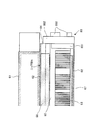
かかる画像形成装置に用いられる定着装置は、図11に示したように、円筒状の芯金111の内部に発熱源113を備え、その芯金111の外周面に離型層112が形成された定着ロール110と、この定着ロール110に対して圧接配置され、芯金121の外周面に耐熱性弾性体層122、および耐熱性樹脂被膜あるいは耐熱性ゴム被膜による離型層123が形成された加圧ロール120とで構成されている。そして、定着ロール110と加圧ロール120との間に、未定着トナー像を担持した記録紙を通過させて、未定着トナー像に対して加熱と加圧とを行うことによって、記録紙にトナー像を定着する。このような定着装置は、加熱ロール方式と呼ばれて、一般に広く利用されている。
As shown in FIG. 11, the fixing device used in such an image forming apparatus includes a
ところで、加熱ロール方式の定着装置において高速化を図ろうとする場合には、トナーと記録紙に充分な熱量が供給できるように、ニップ幅を定着速度に比例して広くすることが必要となる。ニップ幅を広くする方法として、定着ロールと加圧ロールとの間の荷重を大きくする方法や、弾性体層の厚さを厚くする方法、さらにはロール径を大きくする方法がある。
しかし、荷重を大きくする方法や、弾性体層の厚さを厚くする方法では、ロールの撓みに起因するニップ幅の形状がロール軸に沿って不均一になることから、定着むらや紙しわが生じる等といった画像品質上の問題が発生する。また、ロール径を大きくする方法では、装置の大型化を招くとともに、ロールを室温から定着可能温度に上昇させるまでの時間(ウォームアップタイム)が長くなるという問題がある。
By the way, in order to increase the speed of the heating roll type fixing device, it is necessary to increase the nip width in proportion to the fixing speed so that a sufficient amount of heat can be supplied to the toner and the recording paper. As a method of increasing the nip width, there are a method of increasing the load between the fixing roll and the pressure roll, a method of increasing the thickness of the elastic layer, and a method of increasing the roll diameter.
However, in the method of increasing the load or the method of increasing the thickness of the elastic layer, the shape of the nip width due to the deflection of the roll becomes non-uniform along the roll axis. This causes a problem in image quality such as occurrence. In addition, the method of increasing the roll diameter causes problems that the apparatus is increased in size and the time (warm-up time) until the roll is raised from room temperature to a fixable temperature is increased.
そこで、これらの問題を解消して、画像形成装置の高速化に対応した定着装置を実現するべく、本出願人は、表面が弾性変形する回転可能な定着ロールと、この定着ロールに接触したまま走行可能なエンドレスベルトと、このエンドレスベルトの内側に非回転状態で配置された圧力パッドとを具備し、圧力パッドによって、定着ロールとの接触面が形成されるようにエンドレスベルトを定着ロールに圧接させ、エンドレスベルトと定着ロールとの間にシートを通過させることができるようにベルトニップを設けるとともに、定着ロールの表面のうち、シートの出口側を局部的に弾性変形させるように構成した定着装置に関する技術を提案している(例えば、特許文献1参照)。 Therefore, in order to solve these problems and realize a fixing device corresponding to the speeding up of the image forming apparatus, the applicant of the present invention has a rotatable fixing roll whose surface is elastically deformed and remains in contact with the fixing roll. An endless belt capable of traveling and a pressure pad arranged in a non-rotating state inside the endless belt, and the endless belt is pressed against the fixing roll so that a contact surface with the fixing roll is formed by the pressure pad. And a belt nip so that the sheet can be passed between the endless belt and the fixing roll, and a fixing device configured to locally elastically deform the exit side of the sheet on the surface of the fixing roll. The technique regarding this is proposed (for example, refer patent document 1).
かかる特許文献1に記載した定着装置(「ベルトニップ方式」という。)では、従来の加熱ロール方式の定着装置における加圧ロールに代え、圧力部材である圧力パッドを用いてエンドレスベルトを定着ロールに圧接させている。このような構成を採用することにより、定着ロールとエンドレスベルトとによって形成されるベルトニップの幅が従来の定着ロールと加圧ロールとのロールニップの幅よりも容易に大きくすることができるとともに、ニップ部において均一で高いニップ圧を付与することができるので、高速化への対応が可能となり、しかも装置の小型化を図ることも容易である。 In the fixing device (referred to as “belt nip method”) described in Patent Document 1, an endless belt is used as a fixing roll by using a pressure pad as a pressure member instead of the pressure roll in the conventional heating roll type fixing device. Press contact. By adopting such a configuration, the width of the belt nip formed by the fixing roll and the endless belt can be easily made larger than the width of the conventional roll nip between the fixing roll and the pressure roll. Since a uniform and high nip pressure can be applied to the portion, it is possible to cope with a high speed, and it is easy to reduce the size of the apparatus.
さらには、定着ロールに圧接させるエンドレスベルトの熱容量は小さく、加えて圧力パッドが非回転状態で配置されているので、定着ロールから伝わる熱が外部に発散され難い構成を実現している。そのため、定着ロールの回転が開始されても、定着ロールからエンドレスベルト側に奪われる熱量は少なく、トナーの溶融に際しての熱効率を高めることができるとともに、ベルトニップでの温度低下も小さいことから、トナーの定着性の向上を図ることができるという利点も有している。 Furthermore, the heat capacity of the endless belt pressed against the fixing roll is small, and in addition, since the pressure pad is arranged in a non-rotating state, a configuration in which heat transmitted from the fixing roll is not easily dissipated to the outside is realized. Therefore, even when rotation of the fixing roll is started, the amount of heat taken from the fixing roll to the endless belt side is small, the thermal efficiency at the time of melting the toner can be increased, and the temperature drop at the belt nip is also small. There is also an advantage that the fixing property can be improved.
ところで、圧力部材によってエンドレスベルトを定着ロールに圧接させるベルトニップ方式の定着装置においては、エンドレスベルトの両端部に例えばフランジ状の規制部材を配置して、エンドレスベルトの幅方向への移動(ベルトウォーク)を制限し、エンドレスベルトに片寄りが生じることを抑制している。それによって、常に定着ロールとエンドレスベルトとが一定の長手領域で接触する状態を維持するように構成している。 By the way, in a belt nip type fixing device in which an endless belt is pressed against a fixing roll by a pressure member, for example, flange-shaped regulating members are arranged at both ends of the endless belt to move the endless belt in the width direction (belt walk). ) To prevent the endless belt from shifting. Thereby, the fixing roll and the endless belt are always kept in contact with each other in a certain longitudinal region.
しかしながら、画像形成装置が高速化するのに伴ってエンドレスベルトの回動速度も速くなると、エンドレスベルトを幅方向へ移動させる力(スラスト力)もそれに比例して大きくなる。そのため、エンドレスベルトのベルトウォークを規制して片寄りを抑える際に、エンドレスベルトの端部と規制部材との摩擦力も大きなものとなって、エンドレスベルトの両端部で折れや座屈、亀裂等の破損が生じ易くなるという新たな問題が生じる。特に、ベルトニップ方式の定着装置では、圧力部材上に配置された低摩擦部材とエンドレスベルトとの摺擦面に潤滑剤を介在させて、両者の滑り性の向上を図っているので、エンドレスベルトは幅方向へも移動し易くなり、エンドレスベルトの端部と規制部材との摩擦力も大きくなる傾向にある。
そして、かかるエンドレスベルトの両端部における折れや座屈、亀裂等の破損は、エンドレスベルトの円滑な回動を妨げて紙しわや画像不良を引き起こすばかりでなく、最終的にエンドレスベルト自体の破断を生じさせるおそれがある。
However, as the rotational speed of the endless belt increases as the speed of the image forming apparatus increases, the force (thrust force) for moving the endless belt in the width direction also increases proportionally. Therefore, when regulating the belt walk of the endless belt and suppressing the deviation, the frictional force between the end of the endless belt and the regulating member also becomes large, and bending, buckling, cracking, etc. at both ends of the endless belt A new problem arises that breakage tends to occur. In particular, in the belt nip type fixing device, since a lubricant is interposed between the friction surfaces of the low friction member disposed on the pressure member and the endless belt to improve the slipping property of the both, the endless belt Tends to move in the width direction, and the frictional force between the end of the endless belt and the regulating member tends to increase.
And damage such as folding, buckling, cracking, etc. at both ends of the endless belt not only prevents the endless belt from rotating smoothly but also causes paper wrinkles and image defects, but also eventually breaks the endless belt itself. May cause it.
そこで本発明は、以上のような技術的課題を解決するためになされたものであり、その目的とするところは、エンドレスベルトに働くスラスト力を抑えて、エンドレスベルトの両端部での破損の発生を抑制することにある。 Accordingly, the present invention has been made to solve the technical problems as described above, and the object of the present invention is to suppress the thrust force acting on the endless belt and to generate damage at both ends of the endless belt. It is to suppress.
かかる目的のもと、本発明の定着装置は、記録材に担持されたトナー像を定着する定着装置であって、回動可能な回動部材と、回動部材に接触しながら移動可能なエンドレスベルトと、エンドレスベルトの内側に配置され、エンドレスベルトを回動部材に圧接させて回動部材とエンドレスベルトとの間に記録材が通過するニップ部を形成する圧力部材とを備え、エンドレスベルトと圧力部材とは、エンドレスベルトと圧力部材との間の摩擦力が方向により異なるように構成されたことを特徴としている。
ここで、エンドレスベルトは、圧力部材との摩擦力によってエンドレスベルトのスラスト方向への移動が規制されることを特徴とすることもできる。また、圧力部材は、エンドレスベルトとの摺擦面に低摩擦部材が配設された構成とすることができる。
For this purpose, the fixing device of the present invention is a fixing device for fixing a toner image carried on a recording material, and is a rotatable rotating member and an endless movable member in contact with the rotating member. A belt, and a pressure member that is disposed inside the endless belt, presses the endless belt against the rotating member, and forms a nip portion through which the recording material passes between the rotating member and the endless belt. The pressure member is characterized in that the frictional force between the endless belt and the pressure member is different depending on the direction.
Here, the endless belt may be characterized in that movement of the endless belt in the thrust direction is restricted by a frictional force with the pressure member. Further, the pressure member may be configured such that a low friction member is disposed on a friction surface with the endless belt.
また、本発明の定着装置は、記録材に担持されたトナー像を定着する定着装置であって、記録材を搬送する回動可能な回動部材と、回動部材に接触しながら移動可能なエンドレスベルトと、エンドレスベルトの内側に配置され、エンドレスベルトを回動部材に圧接させて回動部材とエンドレスベルトとの間に記録材が通過するニップ部を形成する圧力部材と、エンドレスベルトと圧力部材との間の摺動方向に対する摺擦抵抗を低減する低摩擦部材とを備え、エンドレスベルトと低摩擦部材とは、エンドレスベルトの移動方向の摩擦力よりも移動方向と直交する方向の摩擦力が大きく構成されたことを特徴としている。 The fixing device of the present invention is a fixing device that fixes a toner image carried on a recording material, and is capable of moving while contacting a rotating member that can rotate the recording material and a rotating member that conveys the recording material. An endless belt, a pressure member disposed inside the endless belt, press-contacting the endless belt to the rotating member to form a nip portion through which the recording material passes between the rotating member and the endless belt, and the endless belt and pressure A low friction member that reduces frictional resistance with respect to the sliding direction between the endless belt and the endless belt. The endless belt and the low friction member have a frictional force in a direction perpendicular to the moving direction rather than a frictional force in the moving direction of the endless belt. Is characterized by a large construction.
ここで、エンドレスベルトは、内周面にエンドレスベルトの移動方向に向けて溝または凸部が形成され、低摩擦部材は、エンドレスベルトとの摺擦面に、エンドレスベルトの移動方向に向けて、エンドレスベルトの溝または凸部と嵌合する凸部または溝が形成された構成とすることができる。特に、エンドレスベルトに形成された溝または凸部は、低摩擦部材に形成された凸部または溝とは異なる断面形状を有することを特徴とすることができる。また、エンドレスベルトに形成された溝または凸部と、低摩擦部材に形成された凸部または溝とは、高さまたは深さが4〜20μmで形成することができる。さらには、エンドレスベルトに形成された溝または凸部と、低摩擦部材に形成された凸部または溝とは、幅が120μm以下で形成することもできる。
また、回動部材を加熱する加熱部材、またはエンドレスベルトを加熱する加熱部材をさらに備えたことを特徴とすることができる。
Here, the endless belt has grooves or projections formed on the inner peripheral surface thereof in the direction of movement of the endless belt, and the low friction member is formed on the sliding surface of the endless belt toward the direction of movement of the endless belt. It can be set as the structure in which the convex part or groove | channel which fits the groove | channel or convex part of an endless belt was formed. In particular, the grooves or protrusions formed on the endless belt may have a different cross-sectional shape from the protrusions or grooves formed on the low friction member. Moreover, the groove | channel or convex part formed in the endless belt, and the convex part or groove | channel formed in the low friction member can be formed in 4-20 micrometers in height or depth. Further, the groove or convex portion formed on the endless belt and the convex portion or groove formed on the low friction member can be formed with a width of 120 μm or less.
Moreover, the heating member which heats a rotation member, or the heating member which heats an endless belt can be further provided.
また、本発明を画像形成装置として捉え、本発明の画像形成装置は、トナー像を形成するトナー像形成手段と、トナー像形成手段によって形成されたトナー像を記録材上に転写する転写手段と、記録材上に転写されたトナー像を記録材に定着する定着手段とを含み、定着手段は、記録材を搬送する回動可能な回動部材と、回動部材に接触しながら移動可能なエンドレスベルトと、エンドレスベルトの内側に配置され、エンドレスベルトを回動部材に圧接させて回動部材とエンドレスベルトとの間に記録材が通過するニップ部を形成する圧力部材と、エンドレスベルトと圧力部材との間の摺動方向に対する摺擦抵抗を低減する低摩擦部材とを備え、エンドレスベルトは、内周面にエンドレスベルトの移動方向に向けて溝または凸部が形成され、低摩擦部材は、エンドレスベルトとの摺擦面に、エンドレスベルトの移動方向に向けて、エンドレスベルトの溝または凸部と嵌合する凸部または溝が形成されたことを特徴としている。
ここで、エンドレスベルトが低摩擦部材との摩擦力によってエンドレスベルトのスラスト方向への移動が規制されることを特徴とすることができる。
Further, the present invention is regarded as an image forming apparatus. The image forming apparatus of the present invention includes a toner image forming unit that forms a toner image, and a transfer unit that transfers a toner image formed by the toner image forming unit onto a recording material. A fixing unit that fixes the toner image transferred onto the recording material to the recording material, and the fixing unit is movable while contacting the rotating member and a rotatable rotating member that conveys the recording material. An endless belt, a pressure member disposed inside the endless belt, press-contacting the endless belt to the rotating member to form a nip portion through which the recording material passes between the rotating member and the endless belt, and the endless belt and pressure A low friction member that reduces the frictional resistance with respect to the sliding direction between the member, and the endless belt is formed with a groove or a convex portion on the inner peripheral surface in the moving direction of the endless belt, Friction member, the rubbing surface of an endless belt, toward the moving direction of the endless belt, is characterized in that projections or grooves that grooves or protrusions and the fitting of the endless belt is formed.
Here, the movement of the endless belt in the thrust direction is restricted by the frictional force with the low friction member.
本発明の効果として、エンドレスベルトの両端部での破損の発生を抑制して、長期に亘り紙しわや画像不良等の発生を抑えて高品質な画像を形成することが可能となった。 As an effect of the present invention, it is possible to suppress the occurrence of breakage at both ends of the endless belt and to form a high-quality image while suppressing the occurrence of paper wrinkles and image defects over a long period of time.
以下、添付図面を参照して、本発明の実施の形態について詳細に説明する。
[実施の形態1]
図1は本実施の形態が適用される画像形成装置を示した概略構成図である。図1に示す画像形成装置は、一般にタンデム型と呼ばれる中間転写方式の画像形成装置であって、電子写真方式により各色成分のトナー像が形成される複数の画像形成ユニット1Y,1M,1C,1K、各画像形成ユニット1Y,1M,1C,1Kにより形成された各色成分トナー像を中間転写ベルト15に順次転写(一次転写)させる一次転写部10、中間転写ベルト15上に転写された重畳トナー画像を記録材(記録紙)である用紙Pに一括転写(二次転写)させる二次転写部20、二次転写された画像を用紙P上に定着させる定着装置60を備えている。また、各装置(各部)の動作を制御する制御部40を有している。
Embodiments of the present invention will be described below in detail with reference to the accompanying drawings.
[Embodiment 1]
FIG. 1 is a schematic configuration diagram illustrating an image forming apparatus to which the exemplary embodiment is applied. The image forming apparatus shown in FIG. 1 is an intermediate transfer type image forming apparatus generally called a tandem type, and a plurality of
本実施の形態において、各画像形成ユニット1Y,1M,1C,1Kは、矢印A方向に回転する感光体ドラム11の周囲に、これらの感光体ドラム11を帯電する帯電器12、感光体ドラム11上に静電潜像を書込むレーザ露光器13(図中露光ビームを符号Bmで示す)、各色成分トナーが収容されて感光体ドラム11上の静電潜像をトナーにより可視像化する現像器14、感光体ドラム11上に形成された各色成分トナー像を一次転写部10にて中間転写ベルト15に転写する一次転写ロール16、感光体ドラム11上の残留トナーが除去されるドラムクリーナ17、等の電子写真用デバイスが順次配設されている。これらの画像形成ユニット1Y,1M,1C,1Kは、中間転写ベルト15の上流側から、イエロー(Y)、マゼンタ(M)、シアン(C)、ブラック(K)の順に、略直線状に配置されている。
In the present embodiment, each of the
中間転写体である中間転写ベルト15は、ポリイミドあるいはポリアミド等の樹脂をベース層としてカーボンブラック等の帯電防止剤を適当量含有させたフィルム状の無端ベルトで構成されている。そして、各種ロールによって図1に示すB方向に所定の速度で循環駆動(回動)されている。この各種ロールとして、定速性に優れたモータ(図示せず)により駆動されて中間転写ベルト15を回動させる駆動ロール31、各感光体ドラム11の配列方向に沿って略直線状に延びる中間転写ベルト15を支持する支持ロール32、中間転写ベルト15に対して一定の張力を与えると共に中間転写ベルト15の蛇行を防止する補正ロールとして機能するテンションロール33、二次転写部20に設けられるバックアップロール25、中間転写ベルト15上の残留トナーを掻き取るクリーニング部に設けられるクリーニングバックアップロール34を有している。
The
一次転写部10は、中間転写ベルト15を挟んで感光体ドラム11に対向して配置される一次転写ロール16で構成されている。そして、一次転写ロール16は中間転写ベルト15を挟んで感光体ドラム11に圧接配置され、さらに一次転写ロール16にはトナーの帯電極性(マイナス極性とする。以下同様。)と逆極性の電圧(一次転写バイアス)が印加されるようになっている。これにより、各々の感光体ドラム11上のトナー像が中間転写ベルト15に順次、静電吸引され、中間転写ベルト15上において重畳されたトナー像が形成されるようになっている。
二次転写部20は、中間転写ベルト15のトナー像担持面側に配置される二次転写ロール22と、バックアップロール25とによって構成される。このバックアップロール25は、中間転写ベルト15の裏面側に配置されて二次転写ロール22の対向電極を構成し、二次転写バイアスが安定的に印加される金属製の給電ロール26が当接配置されている。そして、二次転写ロール22は中間転写ベルト15を挟んでバックアップロール25に圧接配置され、さらに二次転写ロール22は接地されてバックアップロール25との間に二次転写バイアスが形成され、二次転写部20に搬送される用紙P上にトナー像を二次転写する。
The
The
また、中間転写ベルト15の二次転写部20の下流側には、二次転写後の中間転写ベルト15上の残留トナーや紙粉を除去し、中間転写ベルト15の表面をクリーニングする中間転写ベルトクリーナ35が接離自在に設けられている。一方、イエローの画像形成ユニット1Yの上流側には、各画像形成ユニット1Y,1M,1C,1Kにおける画像形成タイミングをとるための基準となる基準信号を発生する基準センサ(ホームポジションセンサ)42が配設されている。また、黒の画像形成ユニット1Kの下流側には、画質調整を行うための画像濃度センサ43が配設されている。この基準センサ42は、中間転写ベルト15の裏側に設けられた所定のマークを認識して基準信号を発生しており、この基準信号の認識に基づく制御部40からの指示により、各画像形成ユニット1Y,1M,1C,1Kは画像形成を開始するように構成されている。
Further, on the downstream side of the
さらに、本実施の形態の画像形成装置では、用紙搬送系として、用紙Pを収容する用紙トレイ50、この用紙トレイ50に集積された用紙Pを所定のタイミングで取り出して搬送するピックアップロール51、ピックアップロール51により繰り出された用紙Pを搬送する搬送ロール52、搬送ロール52により搬送された用紙Pを二次転写部20へと送り込む搬送シュート53、二次転写ロール22により二次転写された後に搬送される用紙Pを定着装置60へと搬送する搬送ベルト55、用紙Pを定着装置60に導く定着入口ガイド56を備えている。
Further, in the image forming apparatus according to the present embodiment, as a paper transport system, a
次に、本実施の形態に係る画像形成装置の基本的な作像プロセスについて説明する。図1に示すような画像形成装置では、図示しない画像読取装置(IIT)や図示しないパーソナルコンピュータ(PC)等から出力される画像データは、図示しない画像処理装置(IPS)により所定の画像処理が施された後、画像形成ユニット1Y,1M,1C,1Kによって作像作業が実行される。IPSでは、入力された反射率データに対して、シェーディング補正、位置ズレ補正、明度/色空間変換、ガンマ補正、枠消しや色編集、移動編集等の各種画像編集等の所定の画像処理が施される。画像処理が施された画像データは、Y、M、C、Kの4色の色材階調データに変換され、レーザ露光器13に出力される。
Next, a basic image forming process of the image forming apparatus according to the present embodiment will be described. In an image forming apparatus as shown in FIG. 1, image data output from an image reading device (IIT) not shown or a personal computer (PC) not shown is subjected to predetermined image processing by an image processing device (IPS) not shown. After being applied, the image forming operation is executed by the
レーザ露光器13では、入力された色材階調データに応じて、例えば半導体レーザから出射された露光ビームBmを画像形成ユニット1Y,1M,1C,1Kの各々の感光体ドラム11に照射している。画像形成ユニット1Y,1M,1C,1Kの各感光体ドラム11では、帯電器12によって表面が帯電された後、このレーザ露光器13によって表面が走査露光され、静電潜像が形成される。形成された静電潜像は、各々の画像形成ユニット1Y,1M,1C,1Kによって、Y、M、C、Kの各色のトナー像として現像される。
The
画像形成ユニット1Y,1M,1C,1Kの感光体ドラム11上に形成されたトナー像は、各感光体ドラム11と中間転写ベルト15とが当接する一次転写部10において、中間転写ベルト15上に転写される。より具体的には、一次転写部10において、一次転写ロール16により中間転写ベルト15の基材に対しトナーの帯電極性(マイナス極性)と逆極性の電圧(一次転写バイアス)が付加され、トナー像を中間転写ベルト15の表面に順次重ね合わせて一次転写が行われる。
The toner images formed on the
トナー像が中間転写ベルト15の表面に順次一次転写された後、中間転写ベルト15は移動してトナー像が二次転写部20に搬送される。トナー像が二次転写部20に搬送されると、用紙搬送系では、トナー像が二次転写部20に搬送されるタイミングに合わせてピックアップロール51が回転し、用紙トレイ50から所定サイズの用紙Pが供給される。ピックアップロール51により供給された用紙Pは、搬送ロール52により搬送され、搬送シュート53を経て二次転写部20に到達する。この二次転写部20に到達する前に、用紙Pは一旦停止され、トナー像が担持された中間転写ベルト15の移動タイミングに合わせてレジストロール(図示せず)が回転することで、用紙Pの位置とトナー像の位置との位置合わせがなされる。
After the toner images are sequentially primary transferred onto the surface of the
二次転写部20では、中間転写ベルト15を介して、二次転写ロール22がバックアップロール25に押圧される。このとき、タイミングを合わせて搬送された用紙Pは、中間転写ベルト15と二次転写ロール22との間に挟み込まれる。その際に、給電ロール26からトナーの帯電極性(マイナス極性)と同極性の電圧(二次転写バイアス)が印加されると、二次転写ロール22とバックアップロール25との間に転写電界が形成される。そして、中間転写ベルト15上に担持された未定着トナー像は、二次転写ロール22とバックアップロール25とによって押圧される二次転写部20において、用紙P上に一括して静電転写される。
In the
その後、トナー像が静電転写された用紙Pは、二次転写ロール22によって中間転写ベルト15から剥離された状態でそのまま搬送され、二次転写ロール22の用紙搬送方向下流側に設けられた搬送ベルト55へと搬送される。搬送ベルト55では、定着装置60における最適な搬送速度に合わせて、用紙Pを定着装置60まで搬送する。定着装置60に搬送された用紙P上の未定着トナー像は、定着装置60によって熱および圧力で定着処理を受けることで用紙P上に定着される。そして定着画像が形成された用紙Pは、画像形成装置の排出部に設けられた排紙載置部(不図示)に搬送される。
一方、用紙Pへの転写が終了した後、中間転写ベルト15上に残った残留トナーは、中間転写ベルト15の回動に伴ってクリーニング部まで搬送され、クリーニングバックアップロール34および中間転写ベルトクリーナ35によって中間転写ベルト15上から除去される。
Thereafter, the sheet P on which the toner image has been electrostatically transferred is transported as it is while being peeled off from the
On the other hand, after the transfer onto the paper P is completed, the residual toner remaining on the
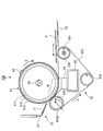
次に、本実施の形態の画像形成装置に用いられる定着装置60について説明する。図2は本実施の形態の定着装置60の構成を示す側断面図である。定着装置60は、回動部材の一例としての定着ロール61、エンドレスベルト62、およびエンドレスベルト62を介して定着ロール61から押圧される圧力部材の一例としての圧力パッド64により主要部が構成されている。
Next, the fixing
定着ロール61は、金属製のコア(円筒状芯金)611の周囲に耐熱性弾性体層612、および離型層613を積層して構成された円筒状ロールであり、回転自在に支持されている。
定着ロール61の内部には、発熱源としてのハロゲンヒータ66が配設されている。一方、定着ロール61の表面には温度センサ69が接触して配置されている。画像形成装置の制御部40は、この温度センサ69による温度計測値に基づいてハロゲンヒータ66の点灯を制御し、定着ロール61の表面温度が所定の設定温度(例えば、150℃)を維持するように調整している。
The fixing
Inside the fixing
エンドレスベルト62は、エンドレスベルト62の内部に配置された圧力パッド64とベルトガイド部材63、さらにはエンドレスベルト62の両端部に配置されたエッジガイド80(後段の図3参照)によって回動自在に支持されている。そして、ニップ部Nにおいて定着ロール61に対して圧接されるように配置されている。
ここで、図3はエンドレスベルト62が支持される構成を説明する断面構成図であり、用紙Pの搬送方向下流側から見た定着装置60の一方の端部領域を示している。
図3に示すように、エンドレスベルト62の内部に配置されたホルダ65の両端部にエッジガイド80が固設されている。エッジガイド80は、ニップ部Nとその近傍に対応する部分に切り欠きが形成された円筒状、すなわち断面がC形状のベルト走行ガイド部801、このベルト走行ガイド部801の外側に設けられ、エンドレスベルト62の内径よりも大きな外径で形成されたフランジ部802、さらにフランジ部802の外側に設けられ、エッジガイド80を定着装置60本体に位置決めして固定するための保持部803で構成されている。
The
Here, FIG. 3 is a cross-sectional configuration diagram illustrating a configuration in which the
As shown in FIG. 3, edge guides 80 are fixed to both end portions of the
そして、エンドレスベルト62は、ニップ部Nとその近傍を除いて、両側部の内周面がベルト走行ガイド部801の外周面に支持され、ベルト走行ガイド部801の外周面に沿って回動する。したがって、ベルト走行ガイド部801は、エンドレスベルト62がスムーズに回動することができるように摩擦係数の小さな材質で形成され、さらには、エンドレスベルト62から熱を奪い難いように熱伝導率の低い材質で形成されている。
また、フランジ部802は、ホルダ65の両端部において対向するように配置された両フランジ部802の内側面が、エンドレスベルト62の幅と略一致する間隔を持つように配置されている。そして、エンドレスベルト62が回動する際には、エンドレスベルト62の端部がフランジ部802の内側面に当接することによって、エンドレスベルト62の幅方向への移動(ベルトウォーク)が制限されている。このように、エンドレスベルト62は、エッジガイド80によって片寄りが規制されるように支持されている。
The
Further, the
また、エンドレスベルト62の両端部を除く長手方向の領域では、エンドレスベルト62は圧力パッド64とベルトガイド部材63とに支持されている(図2も参照)。そして、エンドレスベルト62の両端部を除く領域では、エンドレスベルト62の内周面が圧力パッド64とベルトガイド部材63とに摺擦しながら回動する。
ベルトガイド部材63は、エンドレスベルト62の内部に配置されたホルダ65に取り付けられ、エンドレスベルト62がスムーズに回動することができるように、摩擦係数の小さな材質で形成されている。また、エンドレスベルト62から熱を奪い難いように熱伝導率の低い材質で形成するのが好ましい。
Further, the
The
次に、圧力パッド64は、エンドレスベルト62の内側において、エンドレスベルト62を介して定着ロール61に押圧される状態で配置され、定着ロール61との間でニップ部Nを形成している。圧力パッド64は、幅の広いニップ部Nを確保するためのプレニップ部材64aをニップ部Nの入口側に配置し、定着ロール61に歪み(凹み)を与えるための剥離ニップ部材64bをニップ部Nの出口側に配置している。さらに、エンドレスベルト62の内周面と圧力パッド64との摺動抵抗を小さくするために、プレニップ部材64aおよび剥離ニップ部材64bのエンドレスベルト62と接する面に低摩擦部材の一例としての低摩擦シート68が設けられている。かかる圧力パッド64と低摩擦シート68とは、金属製のホルダ65に支持されている。
Next, the
そして定着ロール61は、図示しない駆動モータに連結されて矢印C方向に回転し、この回転に従動してエンドレスベルト62も定着ロール61と同じ方向に回動する。図1に示した画像形成装置の二次転写部20においてトナー像が静電転写された用紙Pは、定着入口ガイド56によって導かれて、ニップ部Nに搬送される。そして、用紙Pがニップ部Nを通過する際に、用紙P上のトナー像はニップ部Nに作用する圧力と、定着ロール61から供給される熱とによって定着される。本実施の形態の定着装置60では、ほぼ定着ロール61の外周面に倣う凹形状のプレニップ部材64aによりニップ部Nを広く構成することができるため、安定した定着性能を確保することができる。
The fixing
加えて、本実施の形態の定着装置60では、定着ロール61の外周面に対し突出させて剥離ニップ部材64bを配置することにより、ニップ部Nの出口領域(剥離ニップ部)において定着ロール61表面に配置された耐熱性弾性体層612および離型層613に歪み(凹み)が局所的に大きく形成されるように構成している。このように剥離ニップ部材64bを配置すれば、定着後の用紙Pは、剥離ニップ部を通過する際に、局所的に大きく形成された凹みを通過することになるので、この凹みによって用紙Pにはダウンカールが形成され、定着ロール61に巻き付くことのない用紙Pの剥離を効果的に行うことができる。
特に、定着ロール61の凹みを局所的に大きくすることによって、小さい凹み量で高い剥離性能を得ることが可能となる。そのため、定着ロール61の離型層613として、薄膜の耐熱性樹脂を用いた場合においても、用紙Pにおける紙しわの発生を抑制することができる。また、耐熱性弾性体層612と離型層613との間の剥がれ等も発生し難く、剥離性能の維持と併せて長期に亘る部品性能の信頼性を向上させることができる。
In addition, in the fixing
In particular, when the dent of the fixing
さらには、定着ロール61の凹みを局所的に大きくすることによって定着ロール61の凹み量を小さく形成できるので、定着ロール61の耐熱性弾性体層612を薄肉化することができる。そのため、定着ロール61の熱容量を小さく構成できるので、ウォームアップタイムを短くするとともに、消費電力の低減を図ることもできる。また、熱伝導率の低い耐熱性弾性体層612を薄肉化できるため、定着ロール61の内面と外面との間の熱抵抗が小さくなって熱応答性の向上を図れるため、画像形成装置の高速化にも適している。
また、ニップ部Nの下流側近傍には、剥離ニップ部材64bによって定着ロール61から剥離された用紙Pを完全に定着ロール61から分離し、画像形成装置の排出部へ向かう排紙通路に誘導するための剥離補助部材70が配設されている。剥離補助部材70は、剥離バッフル71が定着ロール61の回転方向と対向する向き(カウンタ方向)に定着ロール61と近接する状態でホルダ72によって保持されている。
Furthermore, since the dent amount of the fixing
Further, in the vicinity of the downstream side of the nip portion N, the paper P peeled off from the fixing
次に、定着装置60を構成する各部材について詳細に述べる。まず定着ロール61では、コア(基材)611は、鉄、アルミニウム、SUS等の熱伝導率の高い金属で形成された外径25mm、長さ350mmの円筒体で構成されている。
耐熱性弾性体層612は、耐熱性の高い弾性体で構成され、特に、硬度が15〜45°(JIS−A)程度のゴム、エラストマー等の弾性体を用いるのが好ましい。具体的には、シリコーンゴム、フッ素ゴム等を用いることができる。
Next, each member constituting the fixing
The heat resistant
離型層613には、例えばシリコーン樹脂、フッ素樹脂等の耐熱性樹脂が用いられるが、トナーに対する離型性や耐摩耗性の観点から、フッ素樹脂が適している。フッ素樹脂としては、PFA(テトラフルオロエチレン−パーフルオロアルキルビニルエーテル共重合体)、PTFE(ポリテトラフルオロエチレン)、FEP(テトラフルオロエチレン−ヘキサフルオロプロピレン共重合体)等が使用できる。離型層613の厚みは、好ましくは5〜30μm、より好ましくは10〜20μmに構成している。
For the
エンドレスベルト62は、出力画像に継ぎ目に起因する欠陥が生じないように、原形が直径30mmの円筒形状に形成された継ぎ目がない無端ベルトであり、ベース層と、このベース層の定着ロール61側の面または両面に被覆された離型層とから構成されている。
ベース層は、ポリイミド、ポリアミド、ポリイミドアミド、ポリベンゾイミダゾール等の耐熱性樹脂や、SUS、ニッケル等の金属により形成され、その厚みは、30〜200μm、好ましくは50〜125μm、より好ましくは75〜100μm程度である。また、上記した耐熱性樹脂同士を配合することにより、より強度の高いエンドレスベルト62を形成することも可能である。その場合には、ベース層の厚さを薄く構成できるので、エンドレスベルト62のさらなる低熱容量化が可能となる。
ベース層の表面に被覆される離型層としては、フッ素樹脂、例えばPFA、PTFE、FEPで形成され、その厚みは5〜100μm、好ましくは10〜30μm程度に形成される。離型層は、エンドレスベルト62の表面にトナーが固着することを防ぐために設けたものである。したがって、離型層はベース層の定着ロール61側の面のみに配置した構成とすることもできる。
The
The base layer is formed of a heat-resistant resin such as polyimide, polyamide, polyimide amide, or polybenzimidazole, or a metal such as SUS or nickel, and has a thickness of 30 to 200 μm, preferably 50 to 125 μm, more preferably 75 to It is about 100 μm. Moreover, it is also possible to form the
The release layer coated on the surface of the base layer is formed of a fluororesin such as PFA, PTFE, or FEP, and has a thickness of about 5 to 100 μm, preferably about 10 to 30 μm. The release layer is provided to prevent the toner from adhering to the surface of the
圧力パッド64は、上述したように、プレニップ部材64a、剥離ニップ部材64bで構成され、バネや弾性体によって定着ロール61を付勢するようにホルダ65に支持されている。プレニップ部材64aには、シリコーンゴムやフッ素ゴム等の弾性体や板バネ等を用いることができ、定着ロール61側の面は、ほぼ定着ロール61の外周面に倣う凹形状で形成されている。
剥離ニップ部材64bは、PPS(ポリフェニレンサルファイド)、ポリイミド、ポリエステル、ポリアミド等の耐熱性を有する樹脂、または鉄、アルミニウム、SUS等の金属で形成されている。剥離ニップ部材64bの形状としては、ニップ部Nにおける外面形状が一定の曲率半径を有する凸曲面状に形成されている。
As described above, the
The peeling
低摩擦シート68は、エンドレスベルト62内周面と圧力パッド64との摺動抵抗(摩擦抵抗)を低減するために圧力パッド64のエンドレスベルト62内周面側に設けられ、摩擦係数が小さく、耐摩耗性・耐熱性に優れた材質が適している。具体的には、シンタード成型したPTFE樹脂シート、テフロン(登録商標)を含浸させたガラス繊維シート、またガラス繊維にフッ素樹脂からなるスカイブフィルムシートを加熱融着サンドした積層シート等を用いることができる。
ここで、低摩擦シート68は、圧力パッド64のエンドレスベルト62内周面側に配置される構成であれば、低摩擦シート68を圧力パッド64と別体に構成しても、圧力パッド64と一体的に構成しても、いずれでもよい。
The
Here, if the
また、ホルダ65に配設されたベルトガイド部材63は、上述したように、エンドレスベルト62の内周面と摺擦するため、摩擦係数が低く、かつ、エンドレスベルト62から熱を奪い難いように熱伝導率が低い材質が適しており、PFAやPPS等の耐熱性樹脂が用いられる。
さらに、ホルダ65には、定着装置60の長手方向に亘って潤滑剤塗布部材67が配設されている。潤滑剤塗布部材67は、エンドレスベルト62内周面に対して接触するように配置され、潤滑剤を適量供給する。これにより、エンドレスベルト62と低摩擦シート68との摺動部に潤滑剤を供給し、低摩擦シート68を介したエンドレスベルト62と圧力パッド64との摺動抵抗をさらに低減して、エンドレスベルト62の円滑な回動を図っている。また、エンドレスベルト62の内周面や低摩擦シート68表面の摩耗を防止する効果も有している。
Further, as described above, the
Further, the
ここで、潤滑剤としては、定着温度環境下での長期使用に対する耐久性を有し、かつ、エンドレスベルト62内周面との濡れ性を維持できるものが適している。例えば、シリコーンオイルやフッ素オイル等の液体状のオイルや、固形物質と液体とを混合させたグリース等、さらにはこれらを組み合わせたものを用いることができる。シリコーンオイルとしては、ジメチルシリコーンオイル、アミノ変性シリコーンオイル、カルボキシ変性シリコーンオイル、シラノール変性シリコーンオイル、スルホン酸変性シリコーンオイル等が挙げられるが、摺動抵抗を低減させる効果や取り扱い性の観点から、アミノ変性シリコーンオイルが好適である。
Here, as the lubricant, a lubricant having durability against long-term use under a fixing temperature environment and capable of maintaining wettability with the inner peripheral surface of the
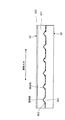
続いて、本実施の形態のエンドレスベルト62の内周面の形状について説明する。図4は、エンドレスベルト62の内周面の形状を説明する図であり、図4(a)にはエンドレスベルト62の内周面の一部を示す平面図、図4(b)、(c)にはエンドレスベルト62の断面形状の例を示している。特に、図4(b)は、図4(a)に示したエンドレスベルト62のXX断面図である。図4に示したように、本実施の形態のエンドレスベルト62は、ベース層621と、このベース層621の外周面に被覆された離型層622とから構成されている。そして、本実施の形態のエンドレスベルト62では、内周面において円周方向(回動方向)に向けて互いに等間隔で平行に、多数の溝623が形成されている。溝623の形状としては、例えば、図4(b)に示したような三角波形状や、図4(c)に示したような矩形波形状等を用いることができる。さらには半円形状等の曲面形状も用いることできる。
Next, the shape of the inner peripheral surface of the
溝623の深さは、エンドレスベルト62の厚さにも拠るが、上記したように、通常エンドレスベルト62の厚さは100μm程度が好適であるため、20μm以下で形成されている。これは、溝623の深さが20μmを超えると、溝623が配設された部分(溝部)のエンドレスベルト62の厚さが薄くなり、エンドレスベルト62の幅方向に関する強度が低下するからである。エンドレスベルト62の幅方向の強度が低下すると、エンドレスベルト62の回動中に溝部で座屈を起こし、用紙Pに紙しわや定着不良等を生じさせたり、さらには、例えば用紙ジャムが発生した場合等においてエンドレスベルト62に外力が加わった際には、エンドレスベルト62が溝部で破断する可能性もある。そのため、エンドレスベルト62の幅方向に関する強度を維持するため、溝623の深さは20μm以下に構成するのが好ましい。なお、溝623はエンドレスベルト62の円周方向(回動方向)に向けて形成されているため、溝623によるエンドレスベルト62の回動方向の強度に対する影響は殆どない。
また、溝623の幅は、120μm以下に設定することが好ましい。溝623の幅を120μmよりも大きく形成すると、後段で説明する低摩擦シート68の表面に設けられた凸部との嵌合によるかみ合わせ効果が低下するからである。
さらに、溝623同士の間隔は、数10〜数100μmに設定されている。
The depth of the
The width of the
Further, the interval between the
ところで、エンドレスベルト62の製造方法としては、エンドレスベルト62をポリイミドのような耐熱性樹脂で形成する場合には、円筒状金属金型の表面に、耐熱性樹脂溶解液(樹脂ワニス)を塗布して耐熱性樹脂塗膜を形成し、これを乾燥させ、乾燥された耐熱性樹脂塗膜に離型層を塗布した後に、この耐熱性樹脂塗膜を焼成する。そして、焼成された耐熱性樹脂皮膜を円筒状金属金型から剥離させる。このようにしてエンドレスベルト62を製造するのが一般的である。したがって、円筒状金属金型の表面に、所望の高さ・形状の凸部または溝を形成することによって、エンドレスベルト62の内周面に溝623を形成することができる。
また、エンドレスベルト62をSUSのような金属で形成する場合には、パイプ状からしごき加工によってベルト状に形成する際に、エンドレスベルト62の内周面に溝623を形成することができる。
By the way, as a manufacturing method of the
Further, when the
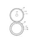
次に、本実施の形態の低摩擦シート68の外表面の形状について説明する。図5は、低摩擦シート68の外表面の形状を説明する図であり、図5(a)には低摩擦シート68の外表面の一部を示す平面図、図5(b)、(c)には低摩擦シート68の断面形状の例を示している。特に、図5(b)は、図5(a)の低摩擦シート68のYY断面図である。図5に示したように、本実施の形態の低摩擦シート68には、エンドレスベルト62の内周面に形成された溝623に対応させて、外表面において用紙P搬送方向(エンドレスベルト62の回動方向)に向けて互いに等間隔で平行に、多数の凸部681が形成されている。凸部681の形状としては、エンドレスベルト62の溝623に対応した、例えば、図5(b)に示したような三角波形状や、図5(c)に示したような台形状等を用いることができる。さらには半円形状等の曲面形状も用いることができる。
Next, the shape of the outer surface of the
ここで、低摩擦シート68の凸部681がエンドレスベルト62の溝623に対し、高さ方向または幅方向の少なくともいずれかに隙間をもって嵌合することができるように、低摩擦シート68の凸部681の断面形状と、エンドレスベルト62の溝623の断面形状とは異なる形状で形成されている。
具体的には、第1のケースとして、凸部681の高さが、エンドレスベルト62の溝623の深さとは異なり(凸部681の高さがエンドレスベルト62の溝623の深さよりも高いか、または低い)、凸部681の幅は、エンドレスベルト62の溝623の幅と同じか、または異なって形成されている場合である。
第2のケースとして、凸部681の幅がエンドレスベルト62の溝623の幅と異なって形成され、凸部681の高さが、エンドレスベルト62の溝623の深さと同じか、または異なるように形成されている場合である。ただし、後段で説明する凸部681と溝623とのかみ合わせ効果を大きくするためには、エンドレスベルト62の溝623の幅は、低摩擦シート68の凸部681の幅よりも大きいほうが好ましい。
その場合に、低摩擦シート68の凸部681とエンドレスベルト62の溝623の一方が三角波形状であって、他方が矩形波形状、台形状、半円形等であるように、両者の形が異なって形成されてもよい。
なお、凸部681同士の幅方向の間隔は、溝623同士の幅方向の間隔と同様に形成されている。
Here, the convex portion of the
Specifically, as a first case, the height of the
As a second case, the width of the
In that case, the shape of the
The interval in the width direction between the
ここで、低摩擦シート68の凸部681の形成方法としては、樹脂シートを成型する際に型によって形成する方法や、また繊維シートを基材とする場合には、繊維の方向をエンドレスベルト62の回動方向に一致させるようにして形成する方法を採用することができる。
また、樹脂シートに型を押圧することによって凸部681を形成することもできる。その際に、樹脂シートを同時に加熱しておくこともできる。
Here, as a method of forming the
Moreover, the
このように、外表面に凸部681が形成された低摩擦シート68と、内周面に溝623が形成されたエンドレスベルト62とは、ニップ部Nにおいて互いに摺動する際に、凸部681と溝623とが嵌合するように位置する。すなわち、溝623(凸部681)同士の間隔は、数10〜数100μmに設定されているため、エンドレスベルト62の回動中の僅かな幅方向への移動(数10〜数100μmの移動)によって凸部681と溝623とは容易に嵌合する。そして、図6に示したように、一旦凸部681と溝623とが嵌合すると、ニップ部Nは押圧されているため、エンドレスベルト62の溝623が低摩擦シート68の凸部681を乗り越えて幅方向へ移動するには大きな幅方向への力が必要となることから、エンドレスベルト62は幅方向への移動が生じ難くなる(「かみ合わせ効果」ともいう。)。その結果、エンドレスベルト62と低摩擦シート68とのスラスト方向(幅方向)の摩擦力が大きく構成されることとなる。
Thus, when the
ところで、エンドレスベルト62は、ニップ部Nにおいて定着ロール61から摩擦力を受けることで駆動力が伝達され、定着ロール61に従動して回動している。ニップ部Nに用紙Pが搬送されている場合にも、用紙Pを介して定着ロール61から摩擦力を受けることで駆動力が伝達される。その際の定着ロール61からエンドレスベルト62への摩擦力は、ニップ部Nにおける定着ロール61と圧力パッド64との間の押圧力(ニップ圧)によって発生することから、エンドレスベルト62が受ける駆動力は、ニップ部Nにおける定着ロール61と圧力パッド64との間のニップ圧によって変動する。すなわち、ニップ部Nにおける幅方向の微小なニップ圧のばらつきや、ニップ部Nに通紙される用紙Pのサイズ、紙厚、紙質等の要因によって、エンドレスベルト62の幅方向にニップ圧分布が生じるために、エンドレスベルト62が定着ロール61から受ける駆動力には、エンドレスベルト62の幅方向に駆動力分布が生じている。そのため、エンドレスベルト62は幅方向における駆動力の不均一性を有しながら、全体として均衡を保って一定の方向に一定の速度で回動している。しかしながら、上記したニップ圧の変動要因等によって、時には相対的にリア側の駆動力が大きくなったり、時には相対的にフロント側の駆動力が大きくなることで、エンドレスベルト62を幅方向へ移動(ベルトウォーク)させる力(「スラスト力」という。)が生じる。そのために、エンドレスベルト62には、リア側またはフロント側への片寄りが発生する場合がある。
By the way, the
これに対し、本実施の形態の定着装置60では、低摩擦シート68とエンドレスベルト62とは、凸部681と溝623とが嵌合しているため、エンドレスベルト62と低摩擦シート68とのスラスト方向(幅方向)の摩擦力が大きくなるように構成されている。そのため、エンドレスベルト62はリア側またはフロント側への片寄りが抑制されることとなる。すなわち、エンドレスベルト62がスラスト力を受けてスラスト方向に移動しようとするのに対して、低摩擦シート68とエンドレスベルト62との間の摩擦力がスラスト方向に対する「ブレーキ」として機能し、エンドレスベルト62のベルトウォークを抑制することができる。そのため、エンドレスベルト62の端部がフランジ部802の内側面に当接するとしても、エンドレスベルト62の端部がフランジ部802の内側面に対して大きなスラスト力で押し付けられことが抑制されるので、両者間の摩擦力は低減され、エンドレスベルト62の両端部における折れや座屈、亀裂等の破損の発生を抑えることが可能となる。
On the other hand, in the fixing
なお、溝623(凸部681)の幅が大きく形成されると、エンドレスベルト62の溝623が低摩擦シート68の凸部681を乗り越え易くなって、エンドレスベルト62が幅方向へ移動し易くなるので、エンドレスベルト62と低摩擦シート68とのスラスト方向の摩擦力を大きく構成することが難しくなる。そのため、上述したように、エンドレスベルト62の溝623と低摩擦シート68の凸部681とのかみ合わせ効果を効果的に作用させるために、溝623(凸部681)の幅は、所定値(120μm)以下に設定するのが好ましい。
また、凸部681の高さが3μm以下と低い場合には、エンドレスベルト62に形成した溝623とのかみ合わせ効果による摩擦力が充分に働かず、エンドレスベルト62と低摩擦シート68とのスラスト方向(幅方向)の摩擦力を大きく構成することが困難となる。そのため、凸部681の高さは4μm以上に形成するのが好ましい。それに対応して、エンドレスベルト62の溝623も、4μm以上に形成するのが好ましい。したがって、上述した条件と合わせて、エンドレスベルト62の溝623の深さは、4〜20μmが好適である。低摩擦シート68の凸部681の高さに関しても、同様に4〜20μmが好適である。
If the width of the groove 623 (the convex portion 681) is formed large, the
When the height of the
さらには、本実施の形態の定着装置60では、エンドレスベルト62の溝623と低摩擦シート68の凸部681とが嵌合している場合を例に説明したが、図7に示したように、エンドレスベルト62の内周面と低摩擦シート68の外表面とを、例えばそれぞれ幅が同じで、深さ/高さが異なる三角波形状の溝および凸部が連続して形成された断面形状とし、それぞれの溝と凸部とを嵌合させた構成とすることもできる。
Furthermore, in the fixing
本実施の形態の定着装置60では、エンドレスベルト62と低摩擦シート68とのスラスト方向(幅方向)の摩擦力が大きく構成されるのに対し、エンドレスベルト62の回動方向においては、低摩擦シート68の凸部681とエンドレスベルト62の溝623とは、回動方向に向けて形成されているため、エンドレスベルト62の回動を妨げる方向の摩擦力は極めて小さく構成されている。
しかも、低摩擦シート68の凸部681がエンドレスベルト62の溝623に対し、高さ方向または幅方向の少なくともいずれかに隙間をもって嵌合するように構成されている。そのため、例えば図6に示したように、低摩擦シート68の凸部681とエンドレスベルト62の溝623とは密着することがなく、接触面積が小さくなるように設定することができる。さらには、両者の隙間には潤滑剤を充分に保持することも可能となる。それによって、エンドレスベルト62の摺動性をさらに向上させる効果が得られ、回動方向の摺動抵抗を低く維持することができる。特に、ニップ圧が印加されたニップ部Nにおいても、潤滑剤を確実に保持することが可能となる。
In the fixing
Moreover, the
その結果、エンドレスベルト62の回動方向における摺動抵抗は極めて低い状態に維持できることから、エンドレスベルト62は円滑に回動することが可能である。そのため、定着ロール61によって搬送される用紙Pがエンドレスベルト62から受ける摺動抵抗は極めて小さいので、用紙Pにおいては、定着ロール61の回転に対応した定着ロール61との等速での搬送が維持され、用紙Pと定着ロール61との間でのスリップの発生を抑制することも可能となる。
As a result, since the sliding resistance in the rotation direction of the
このように、エンドレスベルト62と低摩擦シート68とのスラスト方向(幅方向)の摩擦力が大きくなるように構成することによって、エンドレスベルト62がスラスト力を受けてスラスト方向に移動しようとするのに対して、低摩擦シート68とエンドレスベルト62との間の摩擦力がスラスト力に対する「ブレーキ」として機能し、エンドレスベルト62のベルトウォークを抑制することができる。そのため、エンドレスベルト62の端部がエッジガイド80のフランジ部802の内側面に当接して、エンドレスベルト62の幅方向へのベルトウォークが規制される際に、エンドレスベルト62の端部がフランジ部802の内側面に対して大きなスラスト力で接触することが抑制され、両者の摩擦力は低減される。その結果、エンドレスベルト62の両端部における折れや座屈、亀裂等の破損の発生を抑えることができるので、エンドレスベルト62の円滑な回動を維持することができ、紙しわや画像不良を抑制するばかりでなく、エンドレスベルト62自体の破断を防ぐことも可能となる。
In this way, by configuring the frictional force in the thrust direction (width direction) between the
さらには、低摩擦シート68とエンドレスベルト62とは、エンドレスベルト62の回動方向における摩擦力が極めて小さく構成されているので、エンドレスベルト62は円滑に回動することが可能である。そのため、定着ロール61によって搬送される用紙Pがエンドレスベルト62から受ける摺動抵抗は極めて小さいので、用紙Pにおいては、定着ロール61の回転に対応した定着ロール61との等速での搬送が維持される。その結果、用紙Pと定着ロール61との間でのスリップの発生を抑制して、長期に亘って用紙Pの紙しわや画像ずれのない高品質の画像を形成することも可能となる。
Further, since the
なお、本実施の形態の定着装置60では、外表面に凸部681が形成された低摩擦シート68と、内周面に溝623が形成されたエンドレスベルト62とを用いたが、低摩擦シート68の外表面に溝を形成し、エンドレスベルト62の内周面に凸部を形成した構成を用いることも可能である。
また、低摩擦シート68を用いない場合には、圧力パッド64の表面に直接的に凸部や溝を形成した構成とすることもできる。
In the fixing
Further, when the
以下、実施例およびこれに対する比較例に基づき、本実施の形態のエンドレスベルト62を具体的に説明する。なお、本実施の形態のエンドレスベルト62は実施例に限定されるものではない。
(実施例1)
円筒状金属金型として、切削により円周方向に三角波状の溝部を形成した長さ500mmのアルミニウム製円筒を用い、円筒状金属金型の表面にシリコーン系離型剤(信越化学(株)製:KS700)を塗布し、焼付け処理を行い、室温まで冷却させて、円筒状金属金型表面の離型処理を行った。次に、円筒状金属金型表面に、ポリイミド前駆体溶液(宇部興産(株)製:UワニスS)をフローコート塗布装置によって塗布し、焼成して、膜厚100μmのポリイミド樹脂基材を形成した。その結果、ポリイミド樹脂基材の内周面に、三角波状の凸部が、高さ18μm、幅116μmで形成された。このポリイミド樹脂基材の表面に、厚さ30μmのPFAチューブを、プライマーを介して接着して積層させ、エンドレスベルトを形成した。
低摩擦シートとしては、ガラス繊維基材上にPTFEシートを接着したものを用い、その表面に、深さ25μm、幅130μmの溝を、用紙搬送方向に平行に形成した。
Hereinafter, based on an Example and the comparative example with respect to this, the
(Example 1)
As the cylindrical metal mold, an aluminum cylinder having a length of 500 mm in which a triangular wave groove is formed in the circumferential direction by cutting, a silicone mold release agent (manufactured by Shin-Etsu Chemical Co., Ltd.) is used on the surface of the cylindrical metal mold. : KS700) was applied, baked, and cooled to room temperature, and the release treatment of the surface of the cylindrical metal mold was performed. Next, a polyimide precursor solution (manufactured by Ube Industries, Ltd .: U varnish S) is applied to the surface of the cylindrical metal mold by a flow coat coating apparatus and baked to form a polyimide resin substrate having a thickness of 100 μm. did. As a result, a triangular wave-shaped convex portion was formed with a height of 18 μm and a width of 116 μm on the inner peripheral surface of the polyimide resin substrate. A 30 μm-thick PFA tube was adhered and laminated on the surface of this polyimide resin substrate via a primer to form an endless belt.
As the low-friction sheet, a glass fiber base material bonded with a PTFE sheet was used, and a groove having a depth of 25 μm and a width of 130 μm was formed on the surface thereof in parallel with the paper conveyance direction.
このエンドレスベルトと低摩擦シートとを、エンドレスベルトの回転軸方向と低摩擦シートの幅方向とを一致させて、エンドレスベルトの回転軸方向(低摩擦シートの幅方向)、およびそれに直交する方向(エンドレスベルトの回動方向)の摩擦力を測定したところ、エンドレスベルトの回転軸方向の摩擦力をエンドレスベルトの回動方向の摩擦力よりも大きく構成することができた。
この場合、潤滑剤として、エンドレスベルトの内周面に粘度300csのアミノ変性シリコーンオイルを塗布した。
このポリイミド製エンドレスベルトと低摩擦シートとを、定着装置に搭載し、未定着トナー像を担持した富士ゼロックス(株)製JD紙(商品名)を通紙する試験を行ったところ、20万枚の通紙においても、エンドレスベルトに破断・座屈・割れ等は発生しなかった。また、用紙Pの紙しわや画像ずれの発生も認められなかった。
The endless belt and the low friction sheet are aligned with the rotation axis direction of the endless belt and the width direction of the low friction sheet, and the rotation axis direction of the endless belt (the width direction of the low friction sheet), and the direction orthogonal thereto ( When the frictional force in the direction of rotation of the endless belt was measured, the frictional force in the rotational axis direction of the endless belt could be configured to be greater than the frictional force in the rotational direction of the endless belt.
In this case, an amino-modified silicone oil having a viscosity of 300 cs was applied to the inner peripheral surface of the endless belt as a lubricant.
This polyimide endless belt and low-friction sheet were mounted on a fixing device and tested through Fuji Xerox Co., Ltd. JD paper (trade name) carrying an unfixed toner image. Even when the paper was passed through, the endless belt did not break, buckle or crack. In addition, no paper wrinkles or image misalignment of the paper P was observed.
(実施例2)
実施例1と同様にして、膜厚70μmのポリイミド樹脂基材を形成し、ポリイミド樹脂基材の内周面に、円周方向に高さ6μm、幅90μmの三角波状の凸部を形成した。
低摩擦シートとしては、ガラス繊維基材上にPTFEシートを接着したものを用い、その表面に、深さ15μm、幅100μmの溝を、用紙搬送方向に平行に形成した。
このように形成することによっても、エンドレスベルトの回転軸方向の摩擦力をエンドレスベルトの回動方向の摩擦力よりも大きく構成することができた。
この場合も、実施例1と同様の通紙試験において、20万枚の通紙においても、エンドレスベルトに破断・座屈・割れ等は発生しなかった。また、用紙Pの紙しわや画像ずれの発生も認められなかった。
(Example 2)
In the same manner as in Example 1, a polyimide resin base material having a film thickness of 70 μm was formed, and a triangular wave-shaped convex part having a height of 6 μm and a width of 90 μm was formed on the inner peripheral surface of the polyimide resin base material.
As the low friction sheet, a glass fiber base material bonded with a PTFE sheet was used, and a groove having a depth of 15 μm and a width of 100 μm was formed on the surface thereof in parallel with the paper conveyance direction.
By forming in this way, the frictional force in the rotational axis direction of the endless belt can be configured to be larger than the frictional force in the rotational direction of the endless belt.
In this case as well, in the same paper passing test as in Example 1, no breakage, buckling, cracking, or the like occurred in the endless belt even when 200,000 sheets were passed. In addition, no paper wrinkles or image misalignment of the paper P was observed.
(比較例1)
円筒状金属金型として、表面研磨により凹凸のない長さ500mmのアルミニウム製円筒を用い、円筒状金属金型の表面にシリコーン系離型剤(信越化学(株)製:KS700)を塗布し、焼付け処理を行い、室温まで冷却させて、円筒状金属金型表面の離型処理を行った。次に、円筒状金属金型表面に、ポリイミド前駆体溶液(宇部興産(株)製:UワニスS)をフローコート塗布装置によって塗布し、焼成して、膜厚100μmのポリイミド樹脂基材を形成した。このポリイミド樹脂基材の表面に、厚さ30μmのPFAチューブを、プライマーを介して接着して積層させ、エンドレスベルトを形成した。
低摩擦シートとしては、ガラス繊維基材上に平滑化処理を施したPTFEシートを接着したものを用いた。
(Comparative Example 1)
As the cylindrical metal mold, an aluminum cylinder having a length of 500 mm with no irregularities by surface polishing is used, and a silicone mold release agent (manufactured by Shin-Etsu Chemical Co., Ltd .: KS700) is applied to the surface of the cylindrical metal mold, Baking treatment was performed, and cooling to room temperature was performed to release the surface of the cylindrical metal mold. Next, a polyimide precursor solution (manufactured by Ube Industries, Ltd .: U varnish S) is applied to the surface of the cylindrical metal mold by a flow coat coating apparatus and baked to form a polyimide resin substrate having a thickness of 100 μm. did. A 30 μm-thick PFA tube was adhered and laminated on the surface of this polyimide resin substrate via a primer to form an endless belt.
As the low friction sheet, a glass fiber base material having a smoothed PTFE sheet adhered thereto was used.
このエンドレスベルトと低摩擦シートとを、エンドレスベルトの回転軸方向と低摩擦シートの幅方向とを一致させて、エンドレスベルトの回転軸方向(低摩擦シートの幅方向)、およびそれに直交する方向(エンドレスベルトの回動方向)の摩擦力を測定したところ、方向に拠らず摩擦力は略同等であった。
この場合、潤滑剤として、エンドレスベルトの内周面に粘度300csのアミノ変性シリコーンオイルを塗布した。
このポリイミド製エンドレスベルトと低摩擦シートとを、定着装置に搭載し、未定着トナー像を担持した富士ゼロックス(株)製JD紙(商品名)を通紙する試験を行ったところ、3万枚の通紙を行った時点において、エンドレスベルトの摺動性が悪化し、定着ロールを駆動するモータの駆動トルクが上昇して、定着画像に画像ずれや紙しわが発生した。さらに通紙試験を継続したところ、5万枚の通紙を行った時点で、エッジガイドとの接触部において、エンドレスベルトの端部に割れが生じた。
The endless belt and the low friction sheet are aligned with the rotation axis direction of the endless belt and the width direction of the low friction sheet, and the rotation axis direction of the endless belt (the width direction of the low friction sheet), and the direction orthogonal thereto ( When the frictional force in the rotation direction of the endless belt was measured, the frictional force was substantially the same regardless of the direction.
In this case, an amino-modified silicone oil having a viscosity of 300 cs was applied to the inner peripheral surface of the endless belt as a lubricant.
This polyimide endless belt and low-friction sheet were mounted on a fixing device and tested for passing through JD paper (trade name) manufactured by Fuji Xerox Co., Ltd. carrying an unfixed toner image. When the sheet was fed, the slidability of the endless belt deteriorated, the driving torque of the motor driving the fixing roll increased, and image misalignment and paper wrinkles occurred in the fixed image. Further, when the paper passing test was continued, when 50,000 sheets were passed, the end of the endless belt was cracked at the contact portion with the edge guide.
これは、エンドレスベルトの内周面および低摩擦シートの外表面の両方が平滑化されているため、互いの接触面積が大きくなった結果、エンドレスベルトと低摩擦シートとの摺動抵抗が上昇したことが原因と考えられる。さらに、ともに平滑な界面で、潤滑剤であるアミノ変性シリコーンオイルが、ニップ圧によってニップ部から押し出されたことで、潤滑剤の摺動抵抗軽減化効果が充分に得られなかったことも影響していると考えられる。 This is because both the inner peripheral surface of the endless belt and the outer surface of the low friction sheet are smoothed, and as a result, the contact area between the endless belt and the low friction sheet increases. This is thought to be the cause. Furthermore, both the smooth interface and the amino-modified silicone oil, which is a lubricant, were pushed out of the nip by the nip pressure, and the effect of reducing the sliding resistance of the lubricant was not fully obtained. It is thought that.
(比較例2)
円筒状金属金型として、サンドブラストによりランダムな形状の凹凸が形成された長さ500mmのアルミニウム製円筒を用い、円筒状金属金型の表面にシリコーン系離型剤(信越化学(株)製:KS700)を塗布し、焼付け処理を行い、室温まで冷却させて、円筒状金属金型表面の離型処理を行った。次に、円筒状金属金型表面に、ポリイミド前駆体溶液(宇部興産(株)製:UワニスS)をフローコート塗布装置によって塗布し、焼成して、膜厚70μmのポリイミド樹脂基材を形成した。その結果、ポリイミド樹脂基材の内周面にランダムな形状の凹凸が転写されて、内周面に粗面が形成された。このポリイミド樹脂基材の表面に、厚さ30μmのPFAチューブを、プライマーを介して接着して積層させ、エンドレスベルトを形成した。
低摩擦シートとしては、ガラス繊維基材上にあらかじめサンドブラストにより粗面化処理を施したPTFEシートを接着したものを用いた。
(Comparative Example 2)
As the cylindrical metal mold, an aluminum cylinder having a length of 500 mm on which irregularities of random shape were formed by sandblasting, a silicone mold release agent (manufactured by Shin-Etsu Chemical Co., Ltd .: KS700) was used on the surface of the cylindrical metal mold. ) Was applied, baked, and allowed to cool to room temperature to release the cylindrical metal mold surface. Next, a polyimide precursor solution (manufactured by Ube Industries, Ltd .: U varnish S) is applied to the surface of the cylindrical metal mold by a flow coat coating apparatus and baked to form a polyimide resin base material having a thickness of 70 μm. did. As a result, irregularities having a random shape were transferred to the inner peripheral surface of the polyimide resin base material, and a rough surface was formed on the inner peripheral surface. A 30 μm-thick PFA tube was adhered and laminated on the surface of this polyimide resin substrate via a primer to form an endless belt.
As the low friction sheet, a glass fiber base material bonded with a PTFE sheet that had been roughened by sandblasting in advance was used.
このエンドレスベルトと低摩擦シートとを、エンドレスベルトの回転軸方向と低摩擦シートの幅方向とを一致させて、エンドレスベルトの回転軸方向(低摩擦シートの幅方向)、およびそれに直交する方向(エンドレスベルトの回動方向)の摩擦力を測定したところ、方向に拠らず摩擦力は略同等であった。
この場合、潤滑剤として、エンドレスベルトの内周面に粘度300csのアミノ変性シリコーンオイルを塗布した。
このポリイミド製エンドレスベルトと低摩擦シートとを、定着装置に搭載し、未定着トナー像を担持した富士ゼロックス(株)製JD紙(商品名)を通紙する試験を行ったところ、6万枚の通紙を行った時点において、エンドレスベルトの中央部付近で座屈が発生し始め、さらに通紙試験を継続したところ、7万枚の通紙を行った時点で、エッジガイドとの接触部において、エンドレスベルトの端部に割れが生じた。
The endless belt and the low friction sheet are aligned with the rotation axis direction of the endless belt and the width direction of the low friction sheet, and the rotation axis direction of the endless belt (the width direction of the low friction sheet), and the direction orthogonal thereto ( When the frictional force in the rotation direction of the endless belt was measured, the frictional force was substantially the same regardless of the direction.
In this case, an amino-modified silicone oil having a viscosity of 300 cs was applied to the inner peripheral surface of the endless belt as a lubricant.
When this endless belt made of polyimide and a low friction sheet were mounted on a fixing device and tested through JD paper (trade name) manufactured by Fuji Xerox Co., Ltd. carrying an unfixed toner image, 60,000 sheets were tested. At the time when the paper was passed, buckling began to occur near the center of the endless belt, and when the paper passing test was continued, the contact portion with the edge guide was reached when 70,000 sheets were passed. , Cracks occurred at the end of the endless belt.
これは、エンドレスベルトの内周面と低摩擦シートの外表面とがともに粗面化されているため、潤滑剤の保持能力が大きくなった結果、エンドレスベルトと低摩擦シートとの摺動抵抗の上昇による画像ずれ等の発生はなかったが、エンドレスベルトの回転軸方向と、それに直交する方向(エンドレスベルトの回動方向)の滑り性が同等であるために、エンドレスベルトがスラスト方向に寄りを生じてしまい、エンドレスベルトの寄りを規制しているエッジガイドとの衝突回数が増加し、その際の衝撃によるダメージが最終的にエンドレスベルトの端部に割れを生じさせたものと推測できる。 This is because both the inner peripheral surface of the endless belt and the outer surface of the low friction sheet are roughened, and as a result, the holding capacity of the lubricant is increased, resulting in the sliding resistance between the endless belt and the low friction sheet. Although there was no image misalignment due to ascending, the endless belt moved closer to the thrust direction because the slipperiness in the direction of the axis of rotation of the endless belt and the direction perpendicular to it (the direction of rotation of the endless belt) were the same. It can be presumed that the number of collisions with the edge guide that regulates the deviation of the endless belt increases, and the damage caused by the impact at that time finally caused the end of the endless belt to crack.
(比較例3)
円筒状金属金型として、切削により円周方向に三角波状の溝部を形成した長さ500mmのアルミニウム製円筒を用い、円筒状金属金型の表面にシリコーン系離型剤(信越化学(株)製:KS700)を塗布し、焼付け処理を行い、室温まで冷却させて、円筒状金属金型表面の離型処理を行った。次に、円筒状金属金型表面に、ポリイミド前駆体溶液(宇部興産(株)製:UワニスS)をフローコート塗布装置によって塗布し、焼成して、膜厚70μmのポリイミド樹脂基材を形成した。その結果、ポリイミド樹脂基材の内周面に、三角波状の凸部が、高さ3μm、幅150μmで形成された。このポリイミド樹脂基材の表面に、厚さ30μmのPFAチューブを、プライマーを介して接着して積層させ、エンドレスベルトを形成した。
低摩擦シートとしては、ガラス繊維基材上にPTFEシートを接着したものを用い、その表面に、深さ15μm、幅100μmの溝を、用紙搬送方向に平行に形成した。
(Comparative Example 3)
As the cylindrical metal mold, an aluminum cylinder having a length of 500 mm in which a triangular wave groove is formed in the circumferential direction by cutting, a silicone mold release agent (manufactured by Shin-Etsu Chemical Co., Ltd.) is used on the surface of the cylindrical metal mold. : KS700) was applied, baked, and cooled to room temperature, and the release treatment of the surface of the cylindrical metal mold was performed. Next, a polyimide precursor solution (manufactured by Ube Industries, Ltd .: U varnish S) is applied to the surface of the cylindrical metal mold by a flow coat coating apparatus and baked to form a polyimide resin base material having a thickness of 70 μm. did. As a result, triangular wave-shaped convex portions were formed with a height of 3 μm and a width of 150 μm on the inner peripheral surface of the polyimide resin substrate. A 30 μm-thick PFA tube was adhered and laminated on the surface of this polyimide resin substrate via a primer to form an endless belt.
As the low friction sheet, a glass fiber base material bonded with a PTFE sheet was used, and a groove having a depth of 15 μm and a width of 100 μm was formed on the surface thereof in parallel with the paper conveyance direction.
このエンドレスベルトと低摩擦シートとを、エンドレスベルトの回転軸方向と低摩擦シートの幅方向とを一致させて、エンドレスベルトの回転軸方向(低摩擦シートの幅方向)、およびそれに直交する方向(エンドレスベルトの回動方向)の摩擦力を測定したところ、エンドレスベルトに形成した凸部の高さが低く、低摩擦シートに形成した溝とのかみ合わせによる摩擦力が充分に働かず、方向に拠らず摩擦力は略同等であった。
この場合、潤滑剤として、エンドレスベルトの内周面に粘度300csのアミノ変性シリコーンオイルを塗布した。
このポリイミド製エンドレスベルトと低摩擦シートとを、定着装置に搭載し、未定着トナー像を担持した富士ゼロックス(株)製JD紙(商品名)を通紙する試験を行ったところ、6万枚の通紙を行った時点において、エンドレスベルトの中央部付近で座屈が発生し始め、さらに通紙試験を継続したところ、7万枚の通紙を行った時点で、エッジガイドとの接触部において、エンドレスベルトの端部に割れが生じた。
The endless belt and the low friction sheet are aligned with the rotation axis direction of the endless belt and the width direction of the low friction sheet, and the rotation axis direction of the endless belt (the width direction of the low friction sheet), and the direction orthogonal thereto ( When measuring the frictional force in the direction of rotation of the endless belt, the height of the convex part formed on the endless belt is low, and the frictional force due to the engagement with the groove formed on the low friction sheet does not work sufficiently, depending on the direction. The frictional force was almost the same.
In this case, an amino-modified silicone oil having a viscosity of 300 cs was applied to the inner peripheral surface of the endless belt as a lubricant.
When this endless belt made of polyimide and a low friction sheet were mounted on a fixing device and tested through JD paper (trade name) manufactured by Fuji Xerox Co., Ltd. carrying an unfixed toner image, 60,000 sheets were tested. At the time when the paper was passed, buckling began to occur near the center of the endless belt, and when the paper passing test was continued, the contact portion with the edge guide was reached when 70,000 sheets were passed. , Cracks occurred at the end of the endless belt.
これは、エンドレスベルトの内周面と低摩擦シートの外表面とがともに凹凸を有するため、潤滑剤の保持能力が大きくなった結果、エンドレスベルトと低摩擦シートとの摺動抵抗の上昇による画像ずれ等の発生はなかったが、エンドレスベルトの回転軸方向と、それに直交する方向(エンドレスベルトの回動方向)の滑り性が同等であるために、エンドレスベルトがスラスト方向に寄りを生じてしまい、エンドレスベルトの寄りを規制しているエッジガイドとの衝突回数が増加し、その際の衝撃によるダメージが最終的にエンドレスベルトの端部に割れを生じさせたものと推測できる。 This is because the inner peripheral surface of the endless belt and the outer surface of the low-friction sheet have irregularities, and as a result, the retention capacity of the lubricant is increased, resulting in an increase in sliding resistance between the endless belt and the low-friction sheet. Although there was no deviation, the endless belt was shifted in the thrust direction because the slipperiness in the direction of the axis of rotation of the endless belt and the direction perpendicular to it (the direction of rotation of the endless belt) were equivalent. It can be presumed that the number of collisions with the edge guide that regulates the deviation of the endless belt increases, and the damage caused by the impact at that time finally caused the end of the endless belt to crack.
以上の実施例および比較例の結果をまとめたものが図8である。図8に示したように、本実施の形態のエンドレスベルト62と低摩擦シート68とを用いた定着装置60では、エンドレスベルト62と低摩擦シート68とのスラスト方向(幅方向)の摩擦力を大きく構成することによって、20万枚の通紙においても、エンドレスベルト62での破断・座屈・割れ等の発生を抑制することができる。また、エンドレスベルト62の回動方向における摩擦力が極めて小さく構成されているので、エンドレスベルト62は円滑に回動することが可能となり、紙しわや画像ずれ等の画像不良の発生を抑えることもできる。
かかる本実施の形態のエンドレスベルト62での効果は、比較例との対比によって明確である。
FIG. 8 summarizes the results of the above examples and comparative examples. As shown in FIG. 8, in the fixing
The effect of the
以上説明したように、本実施の形態の定着装置60によれば、エンドレスベルト62と低摩擦シート68とのスラスト方向(幅方向)の摩擦力が大きくなるように構成することによって、エンドレスベルト62の両端部における折れや座屈、亀裂等の破損の発生を抑えることができる。そのため、エンドレスベルト62の円滑な回動を維持することが可能となるばかりでなく、エンドレスベルト62自体が破断することを防ぐことができるので、定着装置60の信頼性をさらに向上させることができる。
さらには、低摩擦シート68とエンドレスベルト62とは、エンドレスベルト62の回動方向における摩擦力が極めて小さく構成されているので、エンドレスベルト62は円滑に回動することが可能である。そのため、用紙Pと定着ロール61との間でのスリップの発生を抑制して、長期に亘って高品質の画像を形成することも可能となる。
As described above, according to the fixing
Further, since the
[実施の形態2]
実施の形態1では、加熱手段として発熱源を有する定着ロール61を用い、加圧手段として圧力パッド64が押圧されたエンドレスベルト62を用いた定着装置60が搭載された画像形成装置について説明した。実施の形態2では、図1に示した画像形成装置に搭載する定着装置であって、加熱手段として発熱源が押圧された定着ベルトを用い、加圧手段として加圧ロールを用いた定着装置について説明する。尚、実施の形態1と同様な構成については同様な符号を用い、ここではその詳細な説明を省略する。
[Embodiment 2]
In the first embodiment, the image forming apparatus is described in which the fixing
図9は、本実施の形態における定着装置90の構成を示す側断面図である。図9に示すように、本実施の形態の定着装置90は、定着ベルト92、回動部材の一例としての加圧ロール91により主要部が構成されている。そして、定着ベルト92が用紙Pのトナー像担持面側に配置されるとともに、定着ベルト92の内側には発熱源の一例としての抵抗発熱体であるセラミックヒータ82が配設され、セラミックヒータ82からニップ部Nに熱を供給するように構成している。
FIG. 9 is a side sectional view showing the configuration of the fixing
セラミックヒータ82は、加圧ロール91側の面がほぼフラットに形成されている。そして、定着ベルト92を介して加圧ロール91に押圧される状態で配置され、ニップ部Nを形成している。したがって、セラミックヒータ82は圧力部材としても機能している。ニップ部Nを通過した用紙Pは、ニップ部Nの出口領域(剥離ニップ部)において定着ベルト92の曲率の変化によって定着ベルト92から剥離される。
さらに、定着ベルト92内周面とセラミックヒータ82との間には、定着ベルト92の内周面とセラミックヒータ82との摺動抵抗を小さくするため、低摩擦シート68が配設されている。この低摩擦シート68は、セラミックヒータ82と別体に構成しても、セラミックヒータ82と一体的に構成しても、いずれでもよい。
The
Further, a
一方、加圧ロール91は定着ベルト92に対向するように配置され、図示しない駆動モータにより矢印D方向に回転し、この回転に従動して定着ベルト92が回動するように構成されている。加圧ロール91は、コア (円柱状芯金)911と、コア911の外周面に被覆した耐熱性弾性体層912と、さらに耐熱性樹脂被覆または耐熱性ゴム被覆による離型層913とが積層されて構成されている。
さらに、本実施の形態の定着装置90では、定着ベルト92は、原形が円筒形状に形成された無端ベルトであり、ポリイミド、ポリアミド、ポリイミドアミド等の耐熱性樹脂やSUS、ニッケル等の金属で形成されたベース層921と、このベース層921の加圧ロール91側の面または両面に被覆されたフッ素樹脂等からなる離型層922とから構成されている。
また、剥離の補助手段として、定着ベルト92のニップ部Nの下流側に、剥離補助部材70を配設することもできる。剥離補助部材70は、剥離バッフル71が定着ベルト92の回転方向と対向する向き(カウンタ方向)に定着ベルト92と近接する状態でホルダ72によって保持されている。
On the other hand, the
Further, in the fixing
Further, as a peeling auxiliary means, a peeling
加えて、ホルダ65の両端部にはエッジガイド(不図示)が配設されている。エッジガイドは、ホルダ65の両端部において対向するように配置された両エッジガイドの内側面が、定着ベルト92の幅と略一致する間隔を持つように配置されている。そして、定着ベルト92が回動する際には、定着ベルト92の端部が両エッジガイドの内側面に当接することによって、定着ベルト92の幅方向への移動(ベルトウォーク)が規制されている。このように、定着ベルト92は、エッジガイドによって片寄りが規制されるように設定されている。
In addition, edge guides (not shown) are disposed at both ends of the
そして、図1に示した画像形成装置の二次転写部20においてトナー像が静電転写された用紙Pは、定着入口ガイド56によって定着装置90のニップ部Nに導かれる。用紙Pがニップ部Nを通過する際には、用紙P上のトナー像は、ニップ部Nに作用する圧力と、定着ベルト92側のセラミックヒータ82から供給される熱とによって定着される。本実施の形態の定着装置90でも、加圧ロール91とセラミックヒータ82との間でニップ部Nを広く構成することができるため、安定した定着性能を確保することができる。
The paper P on which the toner image has been electrostatically transferred in the
本実施の形態の定着装置90では、定着ベルト92には、内周面において円周方向(回動方向)に向けて互いに等間隔で平行に、多数の溝が形成されている。さらに、低摩擦シート68には、定着ベルト92の内周面に形成された溝に対応させて、外表面において用紙P搬送方向(定着ベルト92の回動方向)に向けて互いに等間隔で平行に、多数の凸部が形成されている。このように構成することによって、定着ベルト92と低摩擦シート68とのスラスト方向(幅方向)の摩擦力が大きくなるように構成することができる。そのため、定着ベルト92がスラスト力を受けてスラスト方向に移動しようとするのに対して、低摩擦シート68と定着ベルト92との間の摩擦力がスラスト力に対する「ブレーキ」として機能し、定着ベルト92のベルトウォークを抑制することができる。それによって、定着ベルト92の端部がエッジガイドの内側面に当接して、定着ベルト92の幅方向へのベルトウォークが規制される際に、定着ベルト92の端部がエッジガイドの内側面に対して大きなスラスト力で接触することが抑制されて両者の摩擦力は低減され、定着ベルト92の両端部における折れや座屈、亀裂等の破損の発生を抑えることができる。その結果、定着ベルト92の円滑な回動を維持することができ、紙しわや画像不良を抑制するばかりでなく、定着ベルト92自体の破断を防ぐこともできる。
In the fixing
さらには、低摩擦シート68と定着ベルト92とは、定着ベルト92の回動方向における摩擦力が極めて小さく構成されているので、定着ベルト92は円滑に回動することが可能である。そのため、加圧ロール91によって搬送される用紙Pが定着ベルト92から受ける摺動抵抗は極めて小さいので、用紙Pにおいては、加圧ロール91の回転に対応した加圧ロール91との等速での搬送が維持される。その結果、用紙Pと加圧ロール91との間でのスリップの発生を抑制して、長期に亘って高品質の画像を形成することも可能となる。
Furthermore, since the
[実施の形態3]
実施の形態1では、加熱手段として発熱源を有する定着ロール61を用い、加圧手段として圧力パッド64が押圧されたエンドレスベルト62を用いた定着装置60が搭載された画像形成装置について説明した。実施の形態3では、図1に示した画像形成装置に搭載する定着装置であって、加熱手段として発熱源を有する定着ロールを用い、加圧手段として3本のロールにより張架された加圧ベルトを用いた定着装置について説明する。尚、実施の形態1と同様な構成については同様な符号を用い、ここではその詳細な説明を省略する。
[Embodiment 3]
In the first embodiment, the image forming apparatus is described in which the fixing
図10は本実施の形態の定着装置100の構成を示す側断面図である。この定着装置100は、回動部材の一例としての定着ロール61、加圧ベルト620、加圧ベルト620を介して定着ロール61から押圧される圧力部材の一例としての圧力パッド64により主要部が構成されている。
加圧ベルト620は、インレットロール631、圧力ロール632および張架ロール633の3本のロールにより張架されている。そして、加圧ベルト620は、定着ロール61が矢印E方向へ回転するのに伴い、定着ロール61に従動して矢印F方向に回動する。その進行速度は、定着ロール61の表面速度と同じである。
FIG. 10 is a side sectional view showing the configuration of the fixing
The
加圧ベルト620は、定着ロール61の外周面に当接してニップ部Nを形成しているが、このニップ部Nには、加圧ベルト620の内側に圧力パッド64が加圧ベルト620を介して定着ロール61に向けて付勢された状態で配置されている。したがって、ニップ部Nにおいては、高いニップ圧が均一に付与されている。
また、加圧ベルト620は、ベース層とその表面(定着ロール61側の面、または両面)に被覆された離型層とから構成されている。そして、ベース層としては、耐熱強度の高い樹脂で形成され、例えばポリイミド、ポリアミド、ポリアミドイミド等が適している。ベース層の厚さは、例えば50〜125μm程度に形成される。ベース層の表面に形成される離型層としては、フッ素樹脂、例えばPFA等が5〜20μmの厚さでコーティングされたものが好ましい。さらには、必要であればベース層と離型層との間に厚さ100〜200μmの弾性層を積層させた構成を採ることもできる。弾性層の材料としては、シリコーンゴム等を使用することができる。
The
Further, the
さらに、加圧ベルト620を張架する3個のロールは、ステンレス製のインレットロール631、スチールコアに弾性体層としてシリコーンゴムが被覆された圧力ロール632、およびステンレス製の張架ロール633であり、10kgの張力で加圧ベルト620を張架している。また、インレットロール631の内部には、加熱源としてハロゲンヒータ635が配設されている。そして、図示しない温度センサおよび制御部40(図1参照)によりその表面温度は120℃に制御され、加圧ベルト620に予熱を与えている。
また、圧力ロール632には、両端部にフランジ632aが配設され、圧力ロール632の両端部において対向するように配置された両フランジ632aの内側面が、加圧ベルト620の幅と略一致する間隔を持つように設定されている。そして、加圧ベルト620が回動する際には、加圧ベルト620の端部がフランジ632aの内側面に当接することによって、加圧ベルト620の幅方向への移動(ベルトウォーク)が規制されている。このように、加圧ベルト620は、圧力ロール632の両端部に配置された両フランジ632aによって片寄りが規制されるように設定されている。
なお、圧力ロール632のほか、インレットロール631および張架ロール633の両方、またはいずれか一方においても、ベルトウォークを規制するため、両端部にフランジを配設してもよい。
Further, the three rolls for stretching the
Further, the
In addition to the
次に、押圧部材としての圧力パッド64は、幅の広いニップ部Nを確保するための弾性体部材と、弾性体部材が加圧ベルト620の内周面と接触する面に設けられた低摩擦層とで構成され、金属等からなるホルダ65に保持されている。低摩擦層を表面に有する弾性体部材は、定着ロール61側がほぼ定着ロール61の外周面に倣う凹形状に形成され、定着ロール61に対して押圧されて配置され、ニップ部Nの入口側領域を形成している。弾性体部材としては、シリコーンゴム、フッ素ゴム等の耐熱性の高い弾性体や、板バネ等を用いることができる。弾性体部材上に形成された低摩擦層は、加圧ベルト620内周面と圧力パッド64との摺動抵抗を小さくするために設けられ、摩擦係数が小さく、耐摩耗性のある材質であることが望ましい。具体的には、テフロン(登録商標)を含浸させたガラス繊維シート、フッ素樹脂シート、フッ素樹脂塗膜等を用いることができる。
なお、圧力パッド64としては、本実施の形態のようにパッド状に成型されたものの他に、例えば、ロール状に成型されたものを用いることもでき、加圧ベルト620を介して定着ロール61表面に付勢させて従動回転させてもよい。ただし、本実施の形態のようにパッド状に成型された圧力パッド64の方が、当接するニップ部N全域に亘って、広く均一にニップ圧を付与することができる。
Next, the
The
このような構成により、本実施の形態の定着装置100においては、図1に示した画像形成装置の二次転写部20においてトナー像が静電転写された用紙Pは、定着入口ガイド56によって導かれて、ニップ部Nに搬送され、トナー像を担持した用紙Pは、このニップ部Nを通過する際に加熱および加圧されてトナー像が用紙Pに定着される。本実施の形態の定着装置100でも、ほぼ定着ロール61の外周面に倣う凹形状の圧力パッド64によりニップ部Nを広く構成することができるため、安定した定着性能を確保することができる。
With such a configuration, in the
また、圧力パッド64に対し用紙P搬送方向の下流側に配置された圧力ロール632は、加圧手段としての圧縮コイルスプリング(不図示)によって、加圧ベルト620を介して定着ロール61の中心軸に向けて付勢されており、定着ロール61の当接部に局所的な高圧を生じさせている。それによって、定着ロール61の表面の弾性層612は弾性変形してひずみが生じ、ニップ部Nの出口では、この定着ロール61のひずみにより、用紙Pが定着ロール61側から剥離される。ここで、この定着ロール61に対する局所的な高圧を低荷重で効率良く与えるために、圧力ロール632は定着ロール61より小径で、その表面は硬質に形成されていることが望ましい。
なお、剥離の補助手段として、定着ロール61のニップ部Nの下流側に、剥離補助部材70を配設することもできる。剥離補助部材70は、剥離バッフル71が定着ロール61の回転方向と対向する向き(カウンタ方向)に定着ロール61と近接する状態でホルダ72によって保持されている。
A
Note that, as an auxiliary means for peeling, a peeling
本実施の形態の定着装置100では、加圧ベルト620は、内周面において円周方向(回動方向)に向けて互いに等間隔で平行に、多数の溝が形成されている。さらに、圧力パッド64の低摩擦層には、加圧ベルト620の内周面に形成された溝に対応させて、外表面において用紙P搬送方向(加圧ベルト620の回動方向)に向けて互いに等間隔で平行に、多数の凸部が形成されている。このように構成することによって、加圧ベルト620と圧力パッド64とのスラスト方向(幅方向)の摩擦力が大きくなるように構成することができる。そのため、加圧ベルト620がスラスト力を受けてスラスト方向に移動しようとするのに対して、圧力パッド64と加圧ベルト620との間の摩擦力がスラスト力に対する「ブレーキ」として機能し、加圧ベルト620のベルトウォークを抑制することができる。それによって、加圧ベルト620の端部が圧力ロール632のフランジ632aの内側面に当接して、加圧ベルト620の幅方向へのベルトウォークが規制される際に、加圧ベルト620の端部がフランジ632aの内側面に対して大きなスラスト力で接触することが抑制されることで両者の摩擦力は低減され、加圧ベルト620の両端部における折れや座屈、亀裂等の破損の発生を抑えることができる。その結果、加圧ベルト620の円滑な回動を維持することができ、紙しわや画像不良を抑制するばかりでなく、加圧ベルト620自体の破断を防ぐこともできる。
In the
さらには、圧力パッド64と加圧ベルト620とは、加圧ベルト620の回動方向における摩擦力が極めて小さく構成されているので、加圧ベルト620は円滑に回動することが可能である。そのため、定着ロール61によって搬送される用紙Pが加圧ベルト620から受ける摺動抵抗は極めて小さいので、用紙Pにおいては、定着ロール61の回転に対応した定着ロール61との等速での搬送が維持される。その結果、用紙Pと定着ロール61との間でのスリップの発生を抑制して、長期に亘って高品質の画像を形成することも可能となる。
Furthermore, since the
本発明の活用例として、電子写真方式を用いた複写機、プリンタ等の画像形成装置への適用、例えば記録紙(用紙)上に担持された未定着トナー像を定着する定着装置への適用、さらには転写ベルト、感光体ベルト、帯電ベルトへの適用がある。また、インクジェト方式を用いた複写機、プリンタ等の画像形成装置への適用、例えば記録紙(用紙)上に担持された未乾燥インク像を乾燥する定着装置への適用がある。 As an application example of the present invention, it is applied to an image forming apparatus such as a copying machine or a printer using an electrophotographic method, for example, an application to a fixing device that fixes an unfixed toner image carried on a recording paper (paper), Furthermore, there are applications to transfer belts, photoreceptor belts, and charging belts. Further, there is application to an image forming apparatus such as a copying machine or a printer using an ink jet method, for example, to a fixing device that dries an undried ink image carried on a recording paper (paper).
1Y,1M,1C,1K…画像形成ユニット、11…感光体ドラム、12…帯電器、13…レーザ露光器、14…現像器、15…中間転写ベルト、16…一次転写ロール、17…ドラムクリーナ、20…二次転写部、60,90,100…定着装置、61…定着ロール、62…エンドレスベルト、623…溝、63…ベルトガイド部材、64…圧力パッド、64a…プレニップ部材、64b…剥離ニップ部材、65…ホルダ、66…ハロゲンヒータ、67…潤滑剤塗布部材、68…低摩擦シート、681…凸部、69…温度センサ、70…剥離補助部材、82…セラミックヒータ、91…加圧ロール、92…定着ベルト、620…加圧ベルト、631…インレットロール、632…圧力ロール、632a…フランジ、633…張架ロール 1Y, 1M, 1C, 1K ... image forming unit, 11 ... photosensitive drum, 12 ... charger, 13 ... laser exposure device, 14 ... developing device, 15 ... intermediate transfer belt, 16 ... primary transfer roll, 17 ... drum cleaner , 20 ... secondary transfer part, 60, 90, 100 ... fixing device, 61 ... fixing roll, 62 ... endless belt, 623 ... groove, 63 ... belt guide member, 64 ... pressure pad, 64a ... pre-nip member, 64b ... peeling Nip member, 65 ... Holder, 66 ... Halogen heater, 67 ... Lubricant application member, 68 ... Low friction sheet, 681 ... Projection, 69 ... Temperature sensor, 70 ... Peeling assisting member, 82 ... Ceramic heater, 91 ... Pressurization Roll, 92 ... Fusing belt, 620 ... Pressure belt, 631 ... Inlet roll, 632 ... Pressure roll, 632a ... Flange, 633 ... Stretching roll
Claims (11)
回動可能な回動部材と、
前記回動部材に接触しながら移動可能なエンドレスベルトと、
前記エンドレスベルトの内側に配置され、当該エンドレスベルトを前記回動部材に圧接させて当該回動部材と当該エンドレスベルトとの間に前記記録材が通過するニップ部を形成する圧力部材とを備え、
前記エンドレスベルトと前記圧力部材とは、当該エンドレスベルトと当該圧力部材との間の摩擦力が方向により異なるように構成されたことを特徴とする定着装置。 A fixing device for fixing a toner image carried on a recording material,
A pivotable pivot member;
An endless belt movable while contacting the rotating member;
A pressure member that is disposed inside the endless belt, presses the endless belt against the rotating member, and forms a nip portion through which the recording material passes between the rotating member and the endless belt;
The fixing device, wherein the endless belt and the pressure member are configured such that a frictional force between the endless belt and the pressure member varies depending on a direction.
前記記録材を搬送する回動可能な回動部材と、
前記回動部材に接触しながら移動可能なエンドレスベルトと、
前記エンドレスベルトの内側に配置され、当該エンドレスベルトを前記回動部材に圧接させて当該回動部材と当該エンドレスベルトとの間に前記記録材が通過するニップ部を形成する圧力部材と、
前記エンドレスベルトと前記圧力部材との間の摺動方向に対する摺擦抵抗を低減する低摩擦部材とを備え、
前記エンドレスベルトと前記低摩擦部材とは、当該エンドレスベルトの移動方向の摩擦力よりも当該移動方向と直交する方向の摩擦力が大きく構成されたことを特徴とする定着装置。 A fixing device for fixing a toner image carried on a recording material,
A rotatable turning member for conveying the recording material;
An endless belt movable while contacting the rotating member;
A pressure member that is disposed inside the endless belt, presses the endless belt against the rotating member, and forms a nip portion through which the recording material passes between the rotating member and the endless belt;
A low friction member that reduces the frictional resistance with respect to the sliding direction between the endless belt and the pressure member;
The fixing device, wherein the endless belt and the low friction member are configured such that a frictional force in a direction perpendicular to the moving direction is larger than a frictional force in the moving direction of the endless belt.
前記トナー像形成手段によって形成されたトナー像を記録材上に転写する転写手段と、
前記記録材上に転写されたトナー像を当該記録材に定着する定着手段とを含み、
前記定着手段は、
前記記録材を搬送する回動可能な回動部材と、
前記回動部材に接触しながら移動可能なエンドレスベルトと、
前記エンドレスベルトの内側に配置され、当該エンドレスベルトを前記回動部材に圧接させて当該回動部材と当該エンドレスベルトとの間に前記記録材が通過するニップ部を形成する圧力部材と、
前記エンドレスベルトと前記圧力部材との間の摺動方向に対する摺擦抵抗を低減する低摩擦部材とを備え、
前記エンドレスベルトは、内周面に当該エンドレスベルトの移動方向に向けて溝または凸部が形成され、前記低摩擦部材は、当該エンドレスベルトとの摺擦面に、当該エンドレスベルトの移動方向に向けて、前記エンドレスベルトの溝または凸部と嵌合する凸部または溝が形成されたことを特徴とする画像形成装置。 Toner image forming means for forming a toner image;
Transfer means for transferring the toner image formed by the toner image forming means onto a recording material;
Fixing means for fixing the toner image transferred onto the recording material to the recording material,
The fixing means is
A rotatable turning member for conveying the recording material;
An endless belt movable while contacting the rotating member;
A pressure member that is disposed inside the endless belt, presses the endless belt against the rotating member, and forms a nip portion through which the recording material passes between the rotating member and the endless belt;
A low friction member that reduces the frictional resistance with respect to the sliding direction between the endless belt and the pressure member;
The endless belt has a groove or a convex portion formed on an inner peripheral surface thereof in a moving direction of the endless belt, and the low friction member is directed on a sliding surface with the endless belt in a moving direction of the endless belt. An image forming apparatus characterized in that a convex portion or a groove that fits into the groove or convex portion of the endless belt is formed.
Priority Applications (1)
| Application Number | Priority Date | Filing Date | Title |
|---|---|---|---|
| JP2004083173A JP2005266716A (en) | 2004-03-22 | 2004-03-22 | Fixing device and image forming apparatus |
Applications Claiming Priority (1)
| Application Number | Priority Date | Filing Date | Title |
|---|---|---|---|
| JP2004083173A JP2005266716A (en) | 2004-03-22 | 2004-03-22 | Fixing device and image forming apparatus |
Publications (2)
| Publication Number | Publication Date |
|---|---|
| JP2005266716A true JP2005266716A (en) | 2005-09-29 |
| JP2005266716A5 JP2005266716A5 (en) | 2007-04-12 |
Family
ID=35091277
Family Applications (1)
| Application Number | Title | Priority Date | Filing Date |
|---|---|---|---|
| JP2004083173A Pending JP2005266716A (en) | 2004-03-22 | 2004-03-22 | Fixing device and image forming apparatus |
Country Status (1)
| Country | Link |
|---|---|
| JP (1) | JP2005266716A (en) |
Cited By (4)
| Publication number | Priority date | Publication date | Assignee | Title |
|---|---|---|---|---|
| CN102692856A (en) * | 2011-03-25 | 2012-09-26 | 富士施乐株式会社 | Fixing device and image forming apparatus |
| US8489009B2 (en) | 2010-01-29 | 2013-07-16 | Ricoh Company, Limited | Fixing device and image forming apparatus including same |
| JP2015118157A (en) * | 2013-12-17 | 2015-06-25 | 富士ゼロックス株式会社 | Fixing apparatus and image forming apparatus |
| JP7424022B2 (en) | 2019-12-11 | 2024-01-30 | コニカミノルタ株式会社 | Fixing device and image forming device |
-
2004
- 2004-03-22 JP JP2004083173A patent/JP2005266716A/en active Pending
Cited By (5)
| Publication number | Priority date | Publication date | Assignee | Title |
|---|---|---|---|---|
| US8489009B2 (en) | 2010-01-29 | 2013-07-16 | Ricoh Company, Limited | Fixing device and image forming apparatus including same |
| CN102692856A (en) * | 2011-03-25 | 2012-09-26 | 富士施乐株式会社 | Fixing device and image forming apparatus |
| CN102692856B (en) * | 2011-03-25 | 2015-11-04 | 富士施乐株式会社 | Fixing device and image forming apparatus |
| JP2015118157A (en) * | 2013-12-17 | 2015-06-25 | 富士ゼロックス株式会社 | Fixing apparatus and image forming apparatus |
| JP7424022B2 (en) | 2019-12-11 | 2024-01-30 | コニカミノルタ株式会社 | Fixing device and image forming device |
Similar Documents
| Publication | Publication Date | Title |
|---|---|---|
| US8472855B2 (en) | Fixing device and image forming apparatus incorporating same | |
| JP4951990B2 (en) | Elastic body roll and fixing device | |
| US7398045B2 (en) | Fixing unit and image forming apparatus | |
| JP4706395B2 (en) | Fixing apparatus and image forming apparatus | |
| JP4655822B2 (en) | Fixing apparatus and image forming apparatus | |
| JP4586392B2 (en) | Fixing apparatus and image forming apparatus | |
| JP4595447B2 (en) | Fixing device and image forming apparatus | |
| JP4539252B2 (en) | Fixing device and image forming apparatus | |
| JP5028838B2 (en) | Image fixing apparatus and image forming apparatus | |
| JP5040183B2 (en) | Image forming apparatus and fixing device | |
| JP2005084484A (en) | Fixing device and image forming apparatus | |
| JP6171563B2 (en) | Fixing apparatus and image forming apparatus | |
| JP2006235041A (en) | Fixing device and image forming apparatus | |
| JP2009251311A (en) | Fixing device and image forming apparatus having the same | |
| JP4244837B2 (en) | Image forming apparatus | |
| JP2006091182A (en) | Fixing device, belt tube and image forming apparatus | |
| JP2005266716A (en) | Fixing device and image forming apparatus | |
| JP2005257968A (en) | Fixing device and image forming apparatus | |
| JP2006126536A (en) | Fixing device and image forming apparatus | |
| JP2005249992A (en) | Fixing device and image forming apparatus | |
| JP2008241843A (en) | Fixing device and image forming apparatus | |
| JP2007086530A (en) | Fixing device and image forming apparatus | |
| JP2006126467A (en) | Fixing apparatus and image forming apparatus | |
| US9128436B2 (en) | Fixing device, and image forming apparatus | |
| US10520869B2 (en) | Fixing device and image forming apparatus |
Legal Events
| Date | Code | Title | Description |
|---|---|---|---|
| A521 | Written amendment |
Free format text: JAPANESE INTERMEDIATE CODE: A523 Effective date: 20070222 |
|
| A621 | Written request for application examination |
Free format text: JAPANESE INTERMEDIATE CODE: A621 Effective date: 20070222 |
|
| A131 | Notification of reasons for refusal |
Free format text: JAPANESE INTERMEDIATE CODE: A131 Effective date: 20080513 |
|
| A521 | Written amendment |
Free format text: JAPANESE INTERMEDIATE CODE: A523 Effective date: 20080714 |
|
| A02 | Decision of refusal |
Free format text: JAPANESE INTERMEDIATE CODE: A02 Effective date: 20080826 |