EP1820727B1 - Fahrzeugrad - Google Patents
Fahrzeugrad Download PDFInfo
- Publication number
- EP1820727B1 EP1820727B1 EP06425090A EP06425090A EP1820727B1 EP 1820727 B1 EP1820727 B1 EP 1820727B1 EP 06425090 A EP06425090 A EP 06425090A EP 06425090 A EP06425090 A EP 06425090A EP 1820727 B1 EP1820727 B1 EP 1820727B1
- Authority
- EP
- European Patent Office
- Prior art keywords
- wheel
- shaft
- electrical machine
- energy storage
- storage means
- Prior art date
- Legal status (The legal status is an assumption and is not a legal conclusion. Google has not performed a legal analysis and makes no representation as to the accuracy of the status listed.)
- Not-in-force
Links
Images


Classifications
-
- B—PERFORMING OPERATIONS; TRANSPORTING
- B62—LAND VEHICLES FOR TRAVELLING OTHERWISE THAN ON RAILS
- B62M—RIDER PROPULSION OF WHEELED VEHICLES OR SLEDGES; POWERED PROPULSION OF SLEDGES OR SINGLE-TRACK CYCLES; TRANSMISSIONS SPECIALLY ADAPTED FOR SUCH VEHICLES
- B62M6/00—Rider propulsion of wheeled vehicles with additional source of power, e.g. combustion engine or electric motor
- B62M6/40—Rider propelled cycles with auxiliary electric motor
-
- B—PERFORMING OPERATIONS; TRANSPORTING
- B60—VEHICLES IN GENERAL
- B60L—PROPULSION OF ELECTRICALLY-PROPELLED VEHICLES; SUPPLYING ELECTRIC POWER FOR AUXILIARY EQUIPMENT OF ELECTRICALLY-PROPELLED VEHICLES; ELECTRODYNAMIC BRAKE SYSTEMS FOR VEHICLES IN GENERAL; MAGNETIC SUSPENSION OR LEVITATION FOR VEHICLES; MONITORING OPERATING VARIABLES OF ELECTRICALLY-PROPELLED VEHICLES; ELECTRIC SAFETY DEVICES FOR ELECTRICALLY-PROPELLED VEHICLES
- B60L50/00—Electric propulsion with power supplied within the vehicle
- B60L50/50—Electric propulsion with power supplied within the vehicle using propulsion power supplied by batteries or fuel cells
- B60L50/53—Electric propulsion with power supplied within the vehicle using propulsion power supplied by batteries or fuel cells in combination with an external power supply, e.g. from overhead contact lines
-
- B—PERFORMING OPERATIONS; TRANSPORTING
- B60—VEHICLES IN GENERAL
- B60L—PROPULSION OF ELECTRICALLY-PROPELLED VEHICLES; SUPPLYING ELECTRIC POWER FOR AUXILIARY EQUIPMENT OF ELECTRICALLY-PROPELLED VEHICLES; ELECTRODYNAMIC BRAKE SYSTEMS FOR VEHICLES IN GENERAL; MAGNETIC SUSPENSION OR LEVITATION FOR VEHICLES; MONITORING OPERATING VARIABLES OF ELECTRICALLY-PROPELLED VEHICLES; ELECTRIC SAFETY DEVICES FOR ELECTRICALLY-PROPELLED VEHICLES
- B60L8/00—Electric propulsion with power supply from forces of nature, e.g. sun or wind
- B60L8/003—Converting light into electric energy, e.g. by using photo-voltaic systems
-
- B—PERFORMING OPERATIONS; TRANSPORTING
- B62—LAND VEHICLES FOR TRAVELLING OTHERWISE THAN ON RAILS
- B62M—RIDER PROPULSION OF WHEELED VEHICLES OR SLEDGES; POWERED PROPULSION OF SLEDGES OR SINGLE-TRACK CYCLES; TRANSMISSIONS SPECIALLY ADAPTED FOR SUCH VEHICLES
- B62M6/00—Rider propulsion of wheeled vehicles with additional source of power, e.g. combustion engine or electric motor
- B62M6/40—Rider propelled cycles with auxiliary electric motor
- B62M6/60—Rider propelled cycles with auxiliary electric motor power-driven at axle parts
- B62M6/65—Rider propelled cycles with auxiliary electric motor power-driven at axle parts with axle and driving shaft arranged coaxially
-
- B—PERFORMING OPERATIONS; TRANSPORTING
- B62—LAND VEHICLES FOR TRAVELLING OTHERWISE THAN ON RAILS
- B62M—RIDER PROPULSION OF WHEELED VEHICLES OR SLEDGES; POWERED PROPULSION OF SLEDGES OR SINGLE-TRACK CYCLES; TRANSMISSIONS SPECIALLY ADAPTED FOR SUCH VEHICLES
- B62M6/00—Rider propulsion of wheeled vehicles with additional source of power, e.g. combustion engine or electric motor
- B62M6/80—Accessories, e.g. power sources; Arrangements thereof
- B62M6/85—Solar cells
-
- B—PERFORMING OPERATIONS; TRANSPORTING
- B62—LAND VEHICLES FOR TRAVELLING OTHERWISE THAN ON RAILS
- B62M—RIDER PROPULSION OF WHEELED VEHICLES OR SLEDGES; POWERED PROPULSION OF SLEDGES OR SINGLE-TRACK CYCLES; TRANSMISSIONS SPECIALLY ADAPTED FOR SUCH VEHICLES
- B62M6/00—Rider propulsion of wheeled vehicles with additional source of power, e.g. combustion engine or electric motor
- B62M6/80—Accessories, e.g. power sources; Arrangements thereof
- B62M6/90—Batteries
-
- F—MECHANICAL ENGINEERING; LIGHTING; HEATING; WEAPONS; BLASTING
- F03—MACHINES OR ENGINES FOR LIQUIDS; WIND, SPRING, OR WEIGHT MOTORS; PRODUCING MECHANICAL POWER OR A REACTIVE PROPULSIVE THRUST, NOT OTHERWISE PROVIDED FOR
- F03G—SPRING, WEIGHT, INERTIA OR LIKE MOTORS; MECHANICAL-POWER PRODUCING DEVICES OR MECHANISMS, NOT OTHERWISE PROVIDED FOR OR USING ENERGY SOURCES NOT OTHERWISE PROVIDED FOR
- F03G7/00—Mechanical-power-producing mechanisms, not otherwise provided for or using energy sources not otherwise provided for
- F03G7/08—Mechanical-power-producing mechanisms, not otherwise provided for or using energy sources not otherwise provided for recovering energy derived from swinging, rolling, pitching or like movements, e.g. from the vibrations of a machine
-
- B—PERFORMING OPERATIONS; TRANSPORTING
- B60—VEHICLES IN GENERAL
- B60L—PROPULSION OF ELECTRICALLY-PROPELLED VEHICLES; SUPPLYING ELECTRIC POWER FOR AUXILIARY EQUIPMENT OF ELECTRICALLY-PROPELLED VEHICLES; ELECTRODYNAMIC BRAKE SYSTEMS FOR VEHICLES IN GENERAL; MAGNETIC SUSPENSION OR LEVITATION FOR VEHICLES; MONITORING OPERATING VARIABLES OF ELECTRICALLY-PROPELLED VEHICLES; ELECTRIC SAFETY DEVICES FOR ELECTRICALLY-PROPELLED VEHICLES
- B60L2200/00—Type of vehicles
- B60L2200/12—Bikes
-
- Y—GENERAL TAGGING OF NEW TECHNOLOGICAL DEVELOPMENTS; GENERAL TAGGING OF CROSS-SECTIONAL TECHNOLOGIES SPANNING OVER SEVERAL SECTIONS OF THE IPC; TECHNICAL SUBJECTS COVERED BY FORMER USPC CROSS-REFERENCE ART COLLECTIONS [XRACs] AND DIGESTS
- Y02—TECHNOLOGIES OR APPLICATIONS FOR MITIGATION OR ADAPTATION AGAINST CLIMATE CHANGE
- Y02T—CLIMATE CHANGE MITIGATION TECHNOLOGIES RELATED TO TRANSPORTATION
- Y02T10/00—Road transport of goods or passengers
- Y02T10/60—Other road transportation technologies with climate change mitigation effect
- Y02T10/70—Energy storage systems for electromobility, e.g. batteries
-
- Y—GENERAL TAGGING OF NEW TECHNOLOGICAL DEVELOPMENTS; GENERAL TAGGING OF CROSS-SECTIONAL TECHNOLOGIES SPANNING OVER SEVERAL SECTIONS OF THE IPC; TECHNICAL SUBJECTS COVERED BY FORMER USPC CROSS-REFERENCE ART COLLECTIONS [XRACs] AND DIGESTS
- Y02—TECHNOLOGIES OR APPLICATIONS FOR MITIGATION OR ADAPTATION AGAINST CLIMATE CHANGE
- Y02T—CLIMATE CHANGE MITIGATION TECHNOLOGIES RELATED TO TRANSPORTATION
- Y02T10/00—Road transport of goods or passengers
- Y02T10/60—Other road transportation technologies with climate change mitigation effect
- Y02T10/7072—Electromobility specific charging systems or methods for batteries, ultracapacitors, supercapacitors or double-layer capacitors
Definitions
- the present invention relates to a vehicle wheel of the kind defined in the preamble of claim 1.
- a wheel of this type for a vehicle, in particular for a bicycle, is known from US-B1-6 270 103 .
- This document discloses, inter alia, a bicycle provided with front and rear disk-shaped wheels whose hubs contain an electrical machine adapted to selectively operate as a motor or as a generator.
- the outer surfaces of the wheels carry photovoltaic cells, and a plurality of rechargeable batteries.
- German Utility Model DE 201 18 397 U discloses and illustrates a wheel in which panels of solar cells are mounted to convert solar energy into electrical energy which may be supplied to an electric hub motor under the control of an electronic unit integrated in the wheel hub.
- US Patent Specification 5 316 101 discloses a bicycle in which solar panels are applied to the lateral surfaces of the front wheel in order to recharge banks of batteries secured to the frame and/or to supply an electrical motor which is also secured to the frame and which is friction-coupled to the tyre of the rear wheel.
- An object of the present invention is to provide a wheel of the type specified above, which enables more advanced integration of the components needed to carry out electrical traction and recover kinetic energy and which also enables a drastic simplification of the structure and therefore of the operations for the assembly of the vehicle for which it is intended.
- the at least one rechargeable battery may be a Ni-Cd battery, or a Ni-MH, Li-ion or Li-Pol battery,
- Rechargeable batteries in the form of thin film are disclosed, for instance, in document US-B1 6 982 132 .
- the at least one battery may comprise a planar supercapacitor.
- a vehicle wheel according to the present invention in particular for a bicycle, is shown overall by 1.
- the wheel 1 of Figs. 1, 2 and 4 is in particular adapted to be used as the front wheel of a bicycle.
- this wheel 1 comprises a shaft 2, which is stationary in operation, adapted to be secured to a bearing structure of a vehicle, for instance to the arms 3 of a front fork of a bicycle ( Fig. 1 ) possibly provided with damping means 4.
- the shaft 2 is connected to the arms or branches 3 of the fork by means, for instance, of a known rapid fastening device 5.
- the wheel 1 comprises a rim 6, for instance of light metal alloy, with which a tyre 7, possibly provided internally with an air chamber 8, is associated in a known manner.
- the wheel 1 is of the type with a so-called lenticular shape and comprises a pair of opposing lateral half-shells 9 and 10 whose peripheral portions are connected to the rim 6 and whose central portions extend about the shaft 2 with the interposition of respective rotational supports 11 and 12 such as ball bearings or the like.
- the wheel 1 comprises a reversible rotary electrical machine shown overall by 13. This machine is mounted coaxially about the shaft 2 and is adapted selectively to act as an electrical generator or as an electric motor actuating the wheel 1 to rotate about the shaft 2.
- the electrical machine 13 comprises a casing or carcase 14, substantially of cylindrical shape, mounted to rotate about the shaft 2 and is, for instance, connected to the rotational supports 11 and 12.
- a rotary armature 15 provided with windings 16 is secured inside the carcase 14.
- This armature is substantially annular in shape and extends about a static inductor 17, also of annular shape, secured about the shaft 2.
- This stationary inductor is produced for instance using permanent magnets.
- the wheel 1 is associated with means adapted to convert the solar energy incident on the outer surface of the wheel 1 into electrical energy.
- These converter means may be selected from among the various known types, for instance monocrystalline-silicon, multicrystalline-silicon, string ribbon, thin film, amorphous silicon, cadmium telluride or copper-indium diselenide converters, or converters with an electrochemical junction of dye-sensitised type (Graetzel cell) or polymer or photosynthetic converters.
- these photovoltaic conversion means comprise thin photovoltaic panels applied to the outer lateral surfaces of the half-shells 9 and 10.
- such a photovoltaic panel of annular shape 18 is applied to the outer surface or face of the half-shell 10 about the central portion of the latter surrounding the stationary shaft 2.
- a similar annular panel is advantageously applied to the outer surface or face of the half-shell 9.
- the electrical machine 13 is also associated with electrical energy storage means, advantageously in the form of one or a plurality of planar or thin film batteries 19 applied to at least one lateral portion of the wheel 1 and rotating rigidly therewith.
- electrical energy storage means advantageously in the form of one or a plurality of planar or thin film batteries 19 applied to at least one lateral portion of the wheel 1 and rotating rigidly therewith.
- respective planar or film batteries 19, of substantially annular shape are applied to the inner surfaces of the half-shells 9 and 10.
- planar or film battery or batteries may be applied between the half-shells and the associated photovoltaic panels 18.
- planar or film batteries and thin photovoltaic panels may be applied to various portions of the same outer surface or face of the wheel.
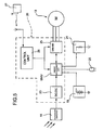
- the electrical machine 13 is also associated with an electronic drive and control unit 20 mounted inside the wheel.
- the components of the electronic drive and control unit 20 are housed in a housing 21 connected to an inner baffle or diaphragm 22 of the wheel.
- the drive and control unit 20 may be physically disposed in locations other than that shown in Figs. 1 and 2 .
- This unit may, for instance, be mounted inside and rigidly with the housing 14 of the electrical machine 13.
- the unit 20 may be mounted rigidly with the stationary shaft 2.
- the drive and control unit 20 comprises a dc/dc converter 23 interposed between the output of the photovoltaic converter(s) 18 and the input of an energy management unit EMU.
- planar or film battery or batteries 19 an energy dissipation device 24, for instance comprising a resistor, and a driver circuit 25 associated with the electrical machine 13 are also connected to the unit EMU.
- the unit EMU and the driver 25 are managed in turn by an electronic control unit 26.
- control signals transmitted by a control device 27, for instance mounted on the handlebars, which may be actuated by the vehicle user to request and control a traction or braking action by means of the machine 13, may be supplied to the control unit.
- control device 27 may be coupled to the control unit 26 in a wireless manner, for instance by radio or by magnetic induction.
- This solution makes it possible to avoid any need for cabling between the control device and the wheel of the invention.
- the wheel may therefore be simply interchanged with a conventional bicycle wheel and, for its use, the control device 27 merely needs to be attached to the handlebars or another part of the bearing frame of the bicycle. This device 27 could simply be worn by the user.
- the control device 27 may in particular be adapted to allow the control of the electromagnetic braking of the wheel in a mode in which the electrical machine 13 acts as an electrical generator with braking action. Similarly, the control device 27 may be adapted to enable the supply intensity of the energy storage system to be regulated.
- the energy management unit EMU is advantageously adapted to allow a flow of electrical energy from the dc/dc converter to the battery or batteries 19 and/or to the driver 25 when the electrical machine 13 is to function as a motor.
- the energy management unit EMU may also be adapted to allow a flow of electrical energy from the battery or batteries 19 to the driver 25 to enable the machine 13 functioning as a motor to be appropriately supplied.
- the unit EMU When the electrical machine 13 is functioning as an electrical generator, the unit EMU enables a flow of electrical energy from the driver 25 to the battery or batteries 19 and possibly to the dissipation device 24 when the battery or batteries 19 are already fully charged.
- the drive and control unit 20 may also be provided with an electrical connection device, such as a socket 28 ( Fig. 5 ), to enable electrical energy to be drawn from the battery or batteries 19 to supply devices external to the wheel 1, for instance lights, etc..
- an electrical connection device such as a socket 28 ( Fig. 5 ) to enable electrical energy to be drawn from the battery or batteries 19 to supply devices external to the wheel 1, for instance lights, etc.
- connection device may possibly be used to recharge the battery or batteries 19 with electrical energy from a source external to the wheel 1.
- FIGs. 6 and 7 show a further wheel of the present invention.
- parts and components already described bear the reference numerals previously used.
- the wheel of Figs. 6 and 7 is a rear bicycle wheel.
- the half-shell 9 is connected to a pack 30 of sprockets or toothed wheels, of different diameters, which cooperate in a known manner with a chain (not shown) and an associated derailer device (also not shown) and make it possible to apply a plurality of different discrete transmission ratios.
- the pack of sprockets 30 is mounted to rotate within the stationary shaft 2 with the interposition of an appropriate rotational support 11.
- the solar panel 18 applied to the outer surface of the half-shell 9 has an annular shape and an inner diameter at least slightly greater than the diameter of the largest of the sprockets of the pack 30.
- the wheel of Figs. 6 and 7 corresponds substantially to the wheel described above with reference to Figs. 1 to 4 .
- Fig. 8 shows a variant of a wheel of the invention, in which a plurality of individual photovoltaic solar panels 18 of standard type and format, readily available commercially, are applied to the lateral surfaces or faces of the wheel. These panels are interconnected with one another and with the drive and control unit 20 in a manner which is not shown.
- Fig. 9 shows a further variant of a wheel of the invention.
- parts and components already described again bear the reference numerals previously used.
- the wheel of Fig. 9 is not of the type with a lenticular shape, but of the type in which a plurality of spokes 31 extends between the hub and the rim.
- spokes are divided into two opposite lateral groups and the electrical machine 13 and the associated drive and control unit 20 are housed in the region comprised between these two groups of spokes.
- photovoltaic solar panels 18 and associated planar or film batteries 19 are advantageously secured to an intermediate structure 32, for instance a disc or a plurality of spokes or the like, which extends between the electrical machine 13 and the rim 6.
- the solar panel(s) 18 and the associated planar or film batteries 19 may be secured directly to the spokes 31.
- Fig. 10 shows a further variant.
- parts and components already described bear the reference numerals previously used.
- Fig. 10 relates to a rear bicycle wheel, but it will be appreciated by persons skilled in the art that such a wheel could also be a front wheel.
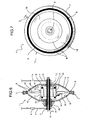
- the variant of Fig. 10 differs from the preceding variants largely in terms of the different configuration of the reversible electrical machine 13.
- the machine 13 comprises a rotor 15 supported by an annular disc 32 rigid with the rim 6 and supported in a rotary manner about the stationary shaft 2 by means of a support 33.
- the rotor 15 comprises two rings 15a and 15b applied to the two main surfaces of the disc 22 and provided with respective rotor windings 16a and 16b.
- the rotor rings 15a, 15b are faced at the front by corresponding permanent-magnet stator rings 17a, 17b secured to corresponding radial flanges 2a, 2b of the stationary shaft 2.
- the inductor or stator While in the embodiments described above the inductor or stator generates a primarily radial magnetic flux about the axis of the shaft 2 and radially faces the armature or rotor via a substantially cylindrical air gap, in the embodiment of Fig. 10 , the inductors 17a, 17b generate a primarily axial flow in operation, parallel to the axis of the shaft 2, and are faced at the front by the associated armatures 15a, 16a and 15b, 16b via air gaps substantially in the form of a thin circular crown.
- the inductor and the armature of the electrical machine 13 may be made from special materials (composite magnetic materials) adapted to enable the production of magnetic circuits in which the magnetic flux does not have a primary direction but is rather directed in different directions in the various sections of the magnetic circuit.
- Fig. 11 shows a further variant of a wheel of the invention for use as a rear bicycle wheel.
- parts and components already described bear the reference numerals previously used.
- Fig. 11 internally comprises a reversible electrical machine of special type adapted to form a transmission ratio system continuously variable in a predetermined range of values.
- Electrical machines of this type are known, for instance from International Patent Application WO 03/051660 in the name of the same applicant.
- the wheel 1 illustrated in Fig. 11 comprises a rim 6 on which two half-shells 9 and 10 are secured and provided, as described above, with outer photovoltaic solar panels 18 and inner planar or film batteries 19.
- the electrical machine 13 comprises a primary rotor 15 structurally similar to that of Fig. 10 and which is not therefore described in further detail.
- the primary rotor 15 faces on one side (the right-hand side when looking at Fig. 11 ) a permanent-magnet stator 17 supported by an annular flange 2b of the stationary shaft 2.
- the primary rotor 15 faces a secondary rotor shown overall by 115.
- This rotor comprises an annular disc 35 carrying a ring 36 with permanent magnets facing the ring 15a of the primary rotor 15.
- the ring 35 is mounted to rotate about the stationary shaft 2 with the interposition of a support 37.
- a tubular projection 35a extends from the disc 35 of the secondary rotor 115, about which projection, externally to the wheel 1, a toothed wheel 40, rigid with the shell 9 and therefore with the rim 6 of the wheel 1, is mounted to rotate.
- a bearing support 11 which also acts as a support between the shell 9 and the tubular projection, is interposed between the toothed wheel 40 and the tubular projection 35a of the secondary rotor 115.
- the special electrical machine 13 of the wheel 1 of Fig. 11 is associated with an electronic control unit (not shown) which is adapted to control this electrical machine so as to provide a continuously variable transmission ratio as a function of control signals supplied to this control unit, for instance by means of a remote control device such as the device 27 of Fig. 5 .
- the wheel 1 of Fig. 11 operates in a similar way to the wheels of the invention described with reference to the preceding Figures.
Claims (17)
- Fahrzeugrad (1), umfassend:eine Welle (2), eingerichtet, um an einer Lagerstruktur des Fahrzeugs gesichert zu werden, und um die das Rad (1) zum Drehen montiert ist,eine umschaltbar drehende elektrische Maschine (13), koaxial um die Welle (2) montiert und eingerichtet, um wahlweise als ein elektrischer Generator und als ein Elektromotor, der das Rad (1) antreibt, zu wirken,Energiespeichereinrichtungen (19), eingerichtet, um mit der elektrischen Maschine (13) gekoppelt zu werden, und wenigstens eine aufladbare im Wesentlichen planare oder Folienbatterie (19) umfassend, die an wenigstens einen Seitenteil des Rades (1) angelegt ist und die starr mit dem Rad (1) rotiert, undfotovoltaische Wandlereinrichtungen (18), mit wenigstens einem Seitenteil des Rades (1) verbunden und eingerichtet, um Sonnenenergieeinstrahlung in elektrische Energie umzuwandeln, die eingerichtet sind, um mit den Energiespeichereinrichtungen (19) gekoppelt zu werden,wobei das Rad (1) dadurch gekennzeichnet ist,dass es des Weiteren elektronische Steuerungseinrichtungen (20) umfasst, die eingerichtet sind, um die elektrische Maschine (13) und die Energiespeichereinrichtungen (13) vorgegebenen Verfahren entsprechend zu steuern, und dadurch, dassdie fotovoltaischen Wandlereinrichtungen (18) und die wenigstens eine planare oder Folienbatterie (19) auf gegenüberliegenden Flächen eines Trägersubstrats (9, 10, 22), das drehstarr mit dem Rad (1) ist, angelegt sind.
- Rad nach Anspruch 1, insbesondere ein linsenförmiges Rad, das ein Paar von gegenüberliegenden seitlichen Halbschalen (9, 10) umfasst und bei dem die fotovoltaischen Wandlereinrichtungen wenigstens einen Sonnenkollektor (18) umfassen, der an eine Fläche wenigstens einer der Halbschalen (9, 10) angelegt ist.
- Rad nach Anspruch 2, wobei die wenigstens eine Halbschale wenigstens teilweise lichtdurchlässig ist und die fotovoltaischen Wandlereinrichtungen an einer Innenfläche dieser wenigstens einen Halbschale angelegt sind.
- Rad nach Anspruch 2 oder 3, wobei der wenigstens eine Sonnenkollektor (19) im Wesentlichen ringförmig ist und in einer im Wesentlichen konzentrischen Anordnung mit der Welle (2) an einer Halbschale (9, 10) angelegt ist.
- Rad nach Anspruch 2 oder 3, das eine Vielzahl von fotovoltaischen Sonnenkollektoren (19), angelegt an einer Halbschale (9, 10) in einer im Wesentlichen konzentrischen Anordnung mit der Welle (2), umfasst.
- Rad nach einem der Ansprüche 2 bis 5, wobei die wenigstens eine planare oder Folienbatterie (19) an der Außen- oder Innenfläche wenigstens einer der Halbschalen (9, 10) angelegt ist.
- Rad nach Anspruch 1, das eine Vielzahl von Speichen (31) umfasst und bei dem die Solarenergiewandlereinrichtungen (18) und die wenigstens eine planare oder Folienbatterie (19) mit diesen Speichen (31) verbunden sind.
- Rad nach einem der vorhergehenden Ansprüche, wobei die elektrische Maschine (13) umfasst:einen feststehenden Induktor (17), starr mit der Welle (2), undeinen drehenden Anker (15), angebracht, um in Bezug auf den Induktor (17) um die Achse der Welle (2) zu drehen, und starr mit den Energiespeichereinrichtungen (19).
- Rad nach Anspruch 8, wobei der Induktor (17) eingerichtet ist, um einen radialen Magnetfluss um die Achse der Welle (2) zu erzeugen und dem Anker (15) über einen im Wesentlichen zylindrischen Luftspalt zugewandt ist.
- Rad nach Anspruch 8, wobei der Induktor (17a, 17b) eingerichtet ist, um einen axialen Magnetfluss, parallel zu der Achse der Welle (2), zu erzeugen und an der Vorderseite dem Anker (15) über einen Luftspalt, im Wesentlichen in Form eines kreisförmigen Kranzes, zugewandt ist.
- Rad nach Anspruch 10, wobei der Induktor einen ersten und einen zweiten ringförmigen Stator (2a, 17a, 2b, 17b) umfasst, die koaxial und starr mit der Welle (2) und parallel zu der Achse der Welle (2) voneinander beabstandet sind, und wobei der Anker (15) eine ringförmige Scheibe (22) umfasst, angeordnet zwischen dem ersten und dem zweiten Stator (2a, 17a, 2b, 17b) und mit einer ersten und einer zweiten Ankerwicklung (16a, 16b) versehen, die in Betrieb jeweils mit dem ersten und dem zweiten Stator (2a, 17a, 2b, 17b) zusammenwirken.
- Rad nach einem der Ansprüche 2 bis 6 und einem der Ansprüche 8 bis 11, wobei die elektrische Maschine (13) in dem Bereich montiert ist, der zwischen den Halbschalen (9, 10) enthalten ist.
- Rad nach Anspruch 7 und einem der Ansprüche 8 bis 11, wobei die elektrische Maschine (13) in einem Bereich montiert ist, der zwischen einer ersten und einer zweiten Seitengruppe von Speichen (31) enthalten ist.
- Rad nach einem der Ansprüche 1 bis 6, wobei die elektrische Maschine (13) einen Anker oder primären Rotor (15), drehstarr mit dem Rad (1), und einen sekundären Rotor (115) umfasst, wobei diese Rotoren (15, 115) in Bezug auf die Welle (2) drehen und die elektrische Maschine (13) des Weiteren einen Stator oder Induktor (17), starr mit der Welle (2), umfasst, wobei die elektrische Maschine (13) so angetrieben werden kann, um ein durchgängig regelbares Übersetzungsverhältnis zwischen einer Drehmomentquelle, die mit dem Rad (1) gekoppelt ist, und dem Rad (1) bereitzustellen.
- Rad nach einem der vorhergehenden Ansprüche, wobei die Sonnenenergieumwandlungseinrichtungen (18) aus Folgendem ausgewählt werden: monokristallines Silizium, multikristallines Silizium, String Ribbon, Dünnschicht, amorphes Silizium, Cadmiumtellurid, Kupfer-Indium-Diselenid-Wandler oder Wandler mit einer elektrochemischen Verbindung des farbstoffsensibilisierten Typs (Grätzel-Zelle) oder polymere fotovoltaische Wandler und fotosynthetische fotovoltaische Wandler.
- Rad nach einem der vorhergehenden Ansprüche, wobei die Elektroenergiespeichereinrichtungen (19) unter Ni-Cd-, Ni-MH-, Li-Ionen- und Li-Pol-Batterien ausgewählt werden.
- Rad nach einem der vorhergehenden Ansprüche 1 bis 15, wobei die Elektroenergiespeichereinrichtungen wenigstens einen Superkondensator umfassen.
Priority Applications (5)
| Application Number | Priority Date | Filing Date | Title |
|---|---|---|---|
| EP06425090A EP1820727B1 (de) | 2006-02-15 | 2006-02-15 | Fahrzeugrad |
| DE602006002717T DE602006002717D1 (de) | 2006-02-15 | 2006-02-15 | Fahrzeugrad |
| AT06425090T ATE407869T1 (de) | 2006-02-15 | 2006-02-15 | Fahrzeugrad |
| US11/673,882 US7495352B2 (en) | 2006-02-15 | 2007-02-12 | Vehicle wheel |
| CN2007100879945A CN101024379B (zh) | 2006-02-15 | 2007-02-15 | 车轮 |
Applications Claiming Priority (1)
| Application Number | Priority Date | Filing Date | Title |
|---|---|---|---|
| EP06425090A EP1820727B1 (de) | 2006-02-15 | 2006-02-15 | Fahrzeugrad |
Publications (2)
| Publication Number | Publication Date |
|---|---|
| EP1820727A1 EP1820727A1 (de) | 2007-08-22 |
| EP1820727B1 true EP1820727B1 (de) | 2008-09-10 |
Family
ID=36688158
Family Applications (1)
| Application Number | Title | Priority Date | Filing Date |
|---|---|---|---|
| EP06425090A Not-in-force EP1820727B1 (de) | 2006-02-15 | 2006-02-15 | Fahrzeugrad |
Country Status (5)
| Country | Link |
|---|---|
| US (1) | US7495352B2 (de) |
| EP (1) | EP1820727B1 (de) |
| CN (1) | CN101024379B (de) |
| AT (1) | ATE407869T1 (de) |
| DE (1) | DE602006002717D1 (de) |
Cited By (1)
| Publication number | Priority date | Publication date | Assignee | Title |
|---|---|---|---|---|
| CN102781768A (zh) * | 2009-12-04 | 2012-11-14 | 麻省理工学院 | 混合式传感器启动电动车轮和相关系统、多毂车轮辐条系统以及制造和安装车轮辐条的方法 |
Families Citing this family (35)
| Publication number | Priority date | Publication date | Assignee | Title |
|---|---|---|---|---|
| DE602006002717D1 (de) * | 2006-02-15 | 2008-10-23 | Fiat Ricerche | Fahrzeugrad |
| DE102007006167A1 (de) * | 2007-02-07 | 2008-08-14 | Ktm Sportmotorcycle Ag | Fahrzeug |
| CN101428674A (zh) * | 2007-11-07 | 2009-05-13 | 王�华 | 动力轮 |
| US8841785B2 (en) * | 2008-04-15 | 2014-09-23 | Infineon Technologies Ag | Energy harvester |
| WO2010091323A1 (en) * | 2009-02-06 | 2010-08-12 | Juan Bautista Belon | Smart electrical wheel for electrical bikes |
| US20120150377A1 (en) * | 2009-08-20 | 2012-06-14 | James Buchhem | Electric motorized bicycle components and a wireless control system including such |
| US20110174554A1 (en) * | 2010-01-18 | 2011-07-21 | William Edward Lee | Solar Powered Wheel Apparatus |
| TWI403426B (zh) * | 2010-08-31 | 2013-08-01 | Chiu Hsiang Lo | Electric car of the overall electric wheel |
| US8419581B2 (en) * | 2010-10-01 | 2013-04-16 | Chiu-Hsiang Lo | Hub motor for electric vehicles |
| US8419580B2 (en) * | 2010-10-01 | 2013-04-16 | Chiu-Hsiang Lo | Electric wheel for electric vehicles |
| TWM421293U (en) * | 2011-07-11 | 2012-01-21 | Fairly Bike Mfg Co Ltd | Assembling structure for bicycle frame and electric hub |
| KR20140038024A (ko) * | 2012-09-19 | 2014-03-28 | 주식회사 만도 | 전기 자전거 |
| DE102013206713A1 (de) * | 2013-04-15 | 2014-10-16 | Robert Bosch Gmbh | Motorisch und mit Muskelkraft betreibbares Fahrzeug |
| DE102013216723A1 (de) * | 2013-08-22 | 2015-02-26 | Robert Bosch Gmbh | Mit Muskelkraft und/oder Motorkraft betreibbares Fahrzeug sowie Verfahren zum Betreiben des Fahrzeugs |
| KR101530170B1 (ko) | 2013-09-17 | 2015-06-19 | 주식회사 만도 | 전기 자전거 |
| US20150203167A1 (en) * | 2014-01-17 | 2015-07-23 | Neal T. Saiki | Front Axle Retention for an Electric Cycle |
| WO2015110869A1 (en) * | 2014-01-24 | 2015-07-30 | Daymak Inc. | Daymak drive system |
| US10005317B2 (en) | 2014-04-04 | 2018-06-26 | Superpedestrian, Inc. | Devices and methods of thermal management for a motorized wheel |
| EP3650262A1 (de) | 2014-04-04 | 2020-05-13 | Superpedestrian, Inc. | Systeme, verfahren und vorrichtungen zum betrieb elektrisch motorisierter fahrzeuge |
| US10308065B2 (en) | 2014-04-04 | 2019-06-04 | Superpedestrian, Inc. | Devices and methods for connecting a spoke to a hub |
| NL2013273B1 (en) | 2014-07-29 | 2016-09-13 | Pip Capital B V | PV-wheel. |
| CN104354601A (zh) * | 2014-10-28 | 2015-02-18 | 刘芳 | 一种智能车轮、智能车轮系统以及轮式车辆 |
| JP2018502549A (ja) | 2014-11-24 | 2018-01-25 | スーパーペデストリアン インク | モータ付きホイールの装置および方法 |
| KR20160074765A (ko) * | 2014-12-18 | 2016-06-29 | 주식회사 만도 | 허브 모터 구조체 |
| CN104691697B (zh) * | 2015-03-18 | 2019-04-02 | 深圳前海零距物联网科技有限公司 | 可控自行车发电装置及发电自行车 |
| FR3036369B1 (fr) * | 2015-05-18 | 2018-08-24 | Rool'in | Roue de vehicule equipee de cellules solaires |
| GB2531623B (en) * | 2015-05-29 | 2017-11-29 | Artemev Timur | Hub motor design |
| US20170259663A1 (en) * | 2016-03-09 | 2017-09-14 | Foster Assets Corporation | Power Wheel and Bicycles Containing the Same |
| IT201600080022A1 (it) * | 2016-07-29 | 2018-01-29 | Zehus S P A | Dinamo per bicicletta |
| DE102017206609A1 (de) | 2017-04-19 | 2018-10-25 | Oliver Thomas Janowski | Energiespeichervorrichtung für ein Fahrzeug |
| CN107416080A (zh) * | 2017-06-15 | 2017-12-01 | 深圳市天克斯技术有限公司 | 具有展示功能的车轮及自行车 |
| DE102018002017B4 (de) * | 2018-03-13 | 2020-08-20 | Heinz Schäfer | Elektrischer Antrieb für zwei- oder mehrrädrige Fahrräder mit einem Pedalantrieb und einer direkt gekoppelten elektrischen Maschine in Schleifringbauweise sowie Verfahren |
| CN111469965B (zh) * | 2020-05-06 | 2020-12-25 | 徐州坤达电动车有限公司 | 一种带有动力回收功能的电动车辅助设备 |
| DE102020116490A1 (de) * | 2020-06-23 | 2021-12-23 | Stein Engineering & Consulting GmbH | Photovoltaikvorrichtung für ein Laufrad eines Fahrrads und Fahrrad |
| WO2022241564A1 (en) * | 2021-05-21 | 2022-11-24 | Transmission Cvtcorp Inc. | Continually variable transmission provided with an electric machine |
Family Cites Families (28)
| Publication number | Priority date | Publication date | Assignee | Title |
|---|---|---|---|---|
| IT7921055V0 (it) * | 1979-03-12 | 1979-03-12 | Catene Calibrate Regina | Gruppo motore per biciclette. |
| US4516647A (en) * | 1982-02-08 | 1985-05-14 | Thaddeus Novak | Solar powered vehicle |
| US5015918A (en) * | 1988-07-22 | 1991-05-14 | John Copeland | Bicycle single-wire lighting system with steady-flashing-reflector rear warning device |
| US4871042A (en) | 1988-09-01 | 1989-10-03 | Hsu Chi Chu | Electric bicycle |
| JPH02306888A (ja) * | 1989-05-22 | 1990-12-20 | Canon Inc | 自転車用太陽電池照明装置 |
| DE3918166A1 (de) * | 1989-06-03 | 1990-12-13 | Gerd Schlueter | Stromversorgungseinrichtung fuer fahrraeder oder dergleichen |
| DE4011565A1 (de) | 1990-04-10 | 1991-10-17 | Wenzel Juergen Michael Dipl Wi | Fahrzeug mit elektrischem antrieb und mit zusaetzlicher energiegewinnung mittels solarzellen an den radseitenflaechen |
| US5121305A (en) * | 1991-04-05 | 1992-06-09 | John Deed | Wheel light |
| US5237263A (en) | 1991-06-17 | 1993-08-17 | Gannon Henry M | Electric and pedal driven bicycle with solar charging |
| AT402281B (de) * | 1991-12-10 | 1997-03-25 | Preisler Erich | Solarantriebsrad |
| US5272938A (en) * | 1992-12-04 | 1993-12-28 | Hsu Chi Hsueh | Flat rim type motor drive mechanism for bicycles |
| US5450915A (en) * | 1993-12-20 | 1995-09-19 | Li; I-Ho | Electric motor-in-wheel |
| JP3480978B2 (ja) * | 1993-12-20 | 2003-12-22 | 輝和 服部 | 太陽電池駆動部付き自転車用車輪 |
| AU3542797A (en) * | 1996-07-09 | 1998-02-02 | Friedrich Grimm | Single track two-wheeled vehicle |
| US6982132B1 (en) | 1997-10-15 | 2006-01-03 | Trustees Of Tufts College | Rechargeable thin film battery and method for making the same |
| IT1297070B1 (it) * | 1997-11-21 | 1999-08-03 | Micronasa Di Patarchi Alberto | Macchina dinamoelettrica rotante a induzione elettromagnetica come agente in motori elettrici lineari. |
| US6064121A (en) * | 1998-02-27 | 2000-05-16 | Hamilton Sundstrand Corporation | Axially compact generator set and refrigeration system employing the same |
| CA2328969C (en) * | 1998-04-17 | 2008-07-22 | Arrowswift, Inc. | Human-powered energy generation and transmission system |
| US5977684A (en) * | 1998-06-12 | 1999-11-02 | Lin; Ted T. | Rotating machine configurable as true DC generator or motor |
| US6888280B2 (en) * | 1999-04-01 | 2005-05-03 | Jean-Yves Dubé | High performance brushless motor and drive for an electrical vehicle motorization |
| JP2000301903A (ja) * | 1999-04-20 | 2000-10-31 | Junji Okazaki | ホイール点灯装置 |
| CN2417054Y (zh) * | 2000-03-10 | 2001-01-31 | 孙玉武 | 太阳能电动助力车 |
| DE20118397U1 (de) * | 2001-11-08 | 2002-03-14 | Schminke Hary | Mit Solarstrom angetriebenes Rad (Fahrrad) |
| ITTO20011171A1 (it) | 2001-12-14 | 2003-06-16 | C R F Societa Con Sortile Per | Sistema di trasmissione a rapporto variabile in modo continuo. |
| US20040021437A1 (en) | 2002-07-31 | 2004-02-05 | Maslov Boris A. | Adaptive electric motors and generators providing improved performance and efficiency |
| DE20315750U1 (de) * | 2003-10-14 | 2003-12-24 | Mühlberger GmbH | Rad mit Elektromotor und Dynamo in der Nabe, wobei der Motor per Batterie oder Solarfläche betrieben wird |
| WO2005039917A1 (fr) | 2003-10-27 | 2005-05-06 | Hongfu Liu | Vélo électrique polyvalent pouvant produire de l'électricité |
| DE602006002717D1 (de) * | 2006-02-15 | 2008-10-23 | Fiat Ricerche | Fahrzeugrad |
-
2006
- 2006-02-15 DE DE602006002717T patent/DE602006002717D1/de active Active
- 2006-02-15 AT AT06425090T patent/ATE407869T1/de not_active IP Right Cessation
- 2006-02-15 EP EP06425090A patent/EP1820727B1/de not_active Not-in-force
-
2007
- 2007-02-12 US US11/673,882 patent/US7495352B2/en not_active Expired - Fee Related
- 2007-02-15 CN CN2007100879945A patent/CN101024379B/zh not_active Expired - Fee Related
Cited By (1)
| Publication number | Priority date | Publication date | Assignee | Title |
|---|---|---|---|---|
| CN102781768A (zh) * | 2009-12-04 | 2012-11-14 | 麻省理工学院 | 混合式传感器启动电动车轮和相关系统、多毂车轮辐条系统以及制造和安装车轮辐条的方法 |
Also Published As
| Publication number | Publication date |
|---|---|
| US7495352B2 (en) | 2009-02-24 |
| ATE407869T1 (de) | 2008-09-15 |
| DE602006002717D1 (de) | 2008-10-23 |
| CN101024379A (zh) | 2007-08-29 |
| US20070187952A1 (en) | 2007-08-16 |
| CN101024379B (zh) | 2011-01-26 |
| EP1820727A1 (de) | 2007-08-22 |
Similar Documents
| Publication | Publication Date | Title |
|---|---|---|
| EP1820727B1 (de) | Fahrzeugrad | |
| CN102317145B (zh) | 自行车传动系统 | |
| CN105656243B (zh) | 电机、电机系统及充电和刹车方法 | |
| CN105939924B (zh) | 电动齿轮马达系统和具有两个或三个轮的车辆 | |
| US5272938A (en) | Flat rim type motor drive mechanism for bicycles | |
| EP2921397B1 (de) | Radnabenmotor eines Elektrofahrrads und Elektrofahrrad mit diesem Radnabenmotor | |
| US8395291B2 (en) | Transverse and/or commutated flux systems for electric bicycles | |
| US9254741B2 (en) | In-wheel actuator and in-wheel assembly comprising the same | |
| CN104079116A (zh) | 电动自行车用可变减速比的轮毂电机 | |
| US20120306327A1 (en) | Electricity generating bicycle wheel assemblies | |
| CN112072840B (zh) | 一种飞轮集成式电动汽车48v机电耦合驱动装置 | |
| WO2012027870A1 (zh) | 永磁无铁芯电动轮毂 | |
| CN105059463A (zh) | 一种一体化轮及采用所述一体化轮的电动车 | |
| CN106956584A (zh) | 多电机多档轮毂动力装置 | |
| CN114475900B (zh) | 电动轮毂驱动总成 | |
| CN204937397U (zh) | 一种一体化轮及采用所述一体化轮的电动车 | |
| CN112644633B (zh) | 电动自行车用定子旋转式轮毂电机 | |
| JP3224745U (ja) | 車輪発電システム | |
| CN103001389A (zh) | 电动自行车用中置电机 | |
| CN220010026U (zh) | 一种混合动力驱动装置及电动自行车 | |
| CN216625548U (zh) | 一种储能轮毂电机 | |
| WO2018142437A1 (en) | Propulsion system for electric vehicles | |
| CN217705496U (zh) | 一种能量可回收的高速电机及电动助力自行车 | |
| CN207843208U (zh) | 一种新型轮毂动力装置及电动自行车 | |
| CN216185779U (zh) | 一种内变速电动双控马达 |
Legal Events
| Date | Code | Title | Description |
|---|---|---|---|
| PUAI | Public reference made under article 153(3) epc to a published international application that has entered the european phase |
Free format text: ORIGINAL CODE: 0009012 |
|
| 17P | Request for examination filed |
Effective date: 20061019 |
|
| AK | Designated contracting states |
Kind code of ref document: A1 Designated state(s): AT BE BG CH CY CZ DE DK EE ES FI FR GB GR HU IE IS IT LI LT LU LV MC NL PL PT RO SE SI SK TR |
|
| AX | Request for extension of the european patent |
Extension state: AL BA HR MK YU |
|
| GRAP | Despatch of communication of intention to grant a patent |
Free format text: ORIGINAL CODE: EPIDOSNIGR1 |
|
| AKX | Designation fees paid |
Designated state(s): AT BE BG CH CY CZ DE DK EE ES FI FR GB GR HU IE IS IT LI LT LU LV MC NL PL PT RO SE SI SK TR |
|
| GRAS | Grant fee paid |
Free format text: ORIGINAL CODE: EPIDOSNIGR3 |
|
| GRAA | (expected) grant |
Free format text: ORIGINAL CODE: 0009210 |
|
| AK | Designated contracting states |
Kind code of ref document: B1 Designated state(s): AT BE BG CH CY CZ DE DK EE ES FI FR GB GR HU IE IS IT LI LT LU LV MC NL PL PT RO SE SI SK TR |
|
| REG | Reference to a national code |
Ref country code: GB Ref legal event code: FG4D |
|
| REG | Reference to a national code |
Ref country code: CH Ref legal event code: EP |
|
| REG | Reference to a national code |
Ref country code: IE Ref legal event code: FG4D |
|
| REF | Corresponds to: |
Ref document number: 602006002717 Country of ref document: DE Date of ref document: 20081023 Kind code of ref document: P |
|
| PG25 | Lapsed in a contracting state [announced via postgrant information from national office to epo] |
Ref country code: LT Free format text: LAPSE BECAUSE OF FAILURE TO SUBMIT A TRANSLATION OF THE DESCRIPTION OR TO PAY THE FEE WITHIN THE PRESCRIBED TIME-LIMIT Effective date: 20080910 |
|
| PG25 | Lapsed in a contracting state [announced via postgrant information from national office to epo] |
Ref country code: SI Free format text: LAPSE BECAUSE OF FAILURE TO SUBMIT A TRANSLATION OF THE DESCRIPTION OR TO PAY THE FEE WITHIN THE PRESCRIBED TIME-LIMIT Effective date: 20080910 Ref country code: LV Free format text: LAPSE BECAUSE OF FAILURE TO SUBMIT A TRANSLATION OF THE DESCRIPTION OR TO PAY THE FEE WITHIN THE PRESCRIBED TIME-LIMIT Effective date: 20080910 Ref country code: AT Free format text: LAPSE BECAUSE OF FAILURE TO SUBMIT A TRANSLATION OF THE DESCRIPTION OR TO PAY THE FEE WITHIN THE PRESCRIBED TIME-LIMIT Effective date: 20080910 Ref country code: FI Free format text: LAPSE BECAUSE OF FAILURE TO SUBMIT A TRANSLATION OF THE DESCRIPTION OR TO PAY THE FEE WITHIN THE PRESCRIBED TIME-LIMIT Effective date: 20080910 |
|
| NLV1 | Nl: lapsed or annulled due to failure to fulfill the requirements of art. 29p and 29m of the patents act | ||
| PG25 | Lapsed in a contracting state [announced via postgrant information from national office to epo] |
Ref country code: BE Free format text: LAPSE BECAUSE OF FAILURE TO SUBMIT A TRANSLATION OF THE DESCRIPTION OR TO PAY THE FEE WITHIN THE PRESCRIBED TIME-LIMIT Effective date: 20080910 |
|
| PG25 | Lapsed in a contracting state [announced via postgrant information from national office to epo] |
Ref country code: BG Free format text: LAPSE BECAUSE OF FAILURE TO SUBMIT A TRANSLATION OF THE DESCRIPTION OR TO PAY THE FEE WITHIN THE PRESCRIBED TIME-LIMIT Effective date: 20081210 Ref country code: ES Free format text: LAPSE BECAUSE OF FAILURE TO SUBMIT A TRANSLATION OF THE DESCRIPTION OR TO PAY THE FEE WITHIN THE PRESCRIBED TIME-LIMIT Effective date: 20081221 |
|
| PG25 | Lapsed in a contracting state [announced via postgrant information from national office to epo] |
Ref country code: PT Free format text: LAPSE BECAUSE OF FAILURE TO SUBMIT A TRANSLATION OF THE DESCRIPTION OR TO PAY THE FEE WITHIN THE PRESCRIBED TIME-LIMIT Effective date: 20090210 Ref country code: CZ Free format text: LAPSE BECAUSE OF FAILURE TO SUBMIT A TRANSLATION OF THE DESCRIPTION OR TO PAY THE FEE WITHIN THE PRESCRIBED TIME-LIMIT Effective date: 20080910 Ref country code: NL Free format text: LAPSE BECAUSE OF FAILURE TO SUBMIT A TRANSLATION OF THE DESCRIPTION OR TO PAY THE FEE WITHIN THE PRESCRIBED TIME-LIMIT Effective date: 20080910 Ref country code: RO Free format text: LAPSE BECAUSE OF FAILURE TO SUBMIT A TRANSLATION OF THE DESCRIPTION OR TO PAY THE FEE WITHIN THE PRESCRIBED TIME-LIMIT Effective date: 20080910 Ref country code: IS Free format text: LAPSE BECAUSE OF FAILURE TO SUBMIT A TRANSLATION OF THE DESCRIPTION OR TO PAY THE FEE WITHIN THE PRESCRIBED TIME-LIMIT Effective date: 20090110 Ref country code: SK Free format text: LAPSE BECAUSE OF FAILURE TO SUBMIT A TRANSLATION OF THE DESCRIPTION OR TO PAY THE FEE WITHIN THE PRESCRIBED TIME-LIMIT Effective date: 20080910 |
|
| PLBE | No opposition filed within time limit |
Free format text: ORIGINAL CODE: 0009261 |
|
| STAA | Information on the status of an ep patent application or granted ep patent |
Free format text: STATUS: NO OPPOSITION FILED WITHIN TIME LIMIT |
|
| PG25 | Lapsed in a contracting state [announced via postgrant information from national office to epo] |
Ref country code: EE Free format text: LAPSE BECAUSE OF FAILURE TO SUBMIT A TRANSLATION OF THE DESCRIPTION OR TO PAY THE FEE WITHIN THE PRESCRIBED TIME-LIMIT Effective date: 20080910 Ref country code: DK Free format text: LAPSE BECAUSE OF FAILURE TO SUBMIT A TRANSLATION OF THE DESCRIPTION OR TO PAY THE FEE WITHIN THE PRESCRIBED TIME-LIMIT Effective date: 20080910 |
|
| 26N | No opposition filed |
Effective date: 20090611 |
|
| PG25 | Lapsed in a contracting state [announced via postgrant information from national office to epo] |
Ref country code: MC Free format text: LAPSE BECAUSE OF NON-PAYMENT OF DUE FEES Effective date: 20090228 |
|
| PG25 | Lapsed in a contracting state [announced via postgrant information from national office to epo] |
Ref country code: IE Free format text: LAPSE BECAUSE OF NON-PAYMENT OF DUE FEES Effective date: 20090215 Ref country code: SE Free format text: LAPSE BECAUSE OF FAILURE TO SUBMIT A TRANSLATION OF THE DESCRIPTION OR TO PAY THE FEE WITHIN THE PRESCRIBED TIME-LIMIT Effective date: 20081210 |
|
| PG25 | Lapsed in a contracting state [announced via postgrant information from national office to epo] |
Ref country code: PL Free format text: LAPSE BECAUSE OF FAILURE TO SUBMIT A TRANSLATION OF THE DESCRIPTION OR TO PAY THE FEE WITHIN THE PRESCRIBED TIME-LIMIT Effective date: 20080910 |
|
| REG | Reference to a national code |
Ref country code: CH Ref legal event code: PL |
|
| GBPC | Gb: european patent ceased through non-payment of renewal fee |
Effective date: 20100215 |
|
| PG25 | Lapsed in a contracting state [announced via postgrant information from national office to epo] |
Ref country code: CH Free format text: LAPSE BECAUSE OF NON-PAYMENT OF DUE FEES Effective date: 20100228 Ref country code: LI Free format text: LAPSE BECAUSE OF NON-PAYMENT OF DUE FEES Effective date: 20100228 Ref country code: GR Free format text: LAPSE BECAUSE OF FAILURE TO SUBMIT A TRANSLATION OF THE DESCRIPTION OR TO PAY THE FEE WITHIN THE PRESCRIBED TIME-LIMIT Effective date: 20081211 |
|
| PG25 | Lapsed in a contracting state [announced via postgrant information from national office to epo] |
Ref country code: GB Free format text: LAPSE BECAUSE OF NON-PAYMENT OF DUE FEES Effective date: 20100215 |
|
| PG25 | Lapsed in a contracting state [announced via postgrant information from national office to epo] |
Ref country code: LU Free format text: LAPSE BECAUSE OF NON-PAYMENT OF DUE FEES Effective date: 20090215 |
|
| PG25 | Lapsed in a contracting state [announced via postgrant information from national office to epo] |
Ref country code: HU Free format text: LAPSE BECAUSE OF FAILURE TO SUBMIT A TRANSLATION OF THE DESCRIPTION OR TO PAY THE FEE WITHIN THE PRESCRIBED TIME-LIMIT Effective date: 20090311 |
|
| PG25 | Lapsed in a contracting state [announced via postgrant information from national office to epo] |
Ref country code: TR Free format text: LAPSE BECAUSE OF FAILURE TO SUBMIT A TRANSLATION OF THE DESCRIPTION OR TO PAY THE FEE WITHIN THE PRESCRIBED TIME-LIMIT Effective date: 20080910 |
|
| PG25 | Lapsed in a contracting state [announced via postgrant information from national office to epo] |
Ref country code: CY Free format text: LAPSE BECAUSE OF FAILURE TO SUBMIT A TRANSLATION OF THE DESCRIPTION OR TO PAY THE FEE WITHIN THE PRESCRIBED TIME-LIMIT Effective date: 20080910 |
|
| REG | Reference to a national code |
Ref country code: FR Ref legal event code: PLFP Year of fee payment: 11 |
|
| REG | Reference to a national code |
Ref country code: FR Ref legal event code: PLFP Year of fee payment: 12 |
|
| REG | Reference to a national code |
Ref country code: FR Ref legal event code: PLFP Year of fee payment: 13 |
|
| PGFP | Annual fee paid to national office [announced via postgrant information from national office to epo] |
Ref country code: FR Payment date: 20180228 Year of fee payment: 13 Ref country code: IT Payment date: 20180209 Year of fee payment: 13 |
|
| PGFP | Annual fee paid to national office [announced via postgrant information from national office to epo] |
Ref country code: DE Payment date: 20180430 Year of fee payment: 13 |
|
| REG | Reference to a national code |
Ref country code: DE Ref legal event code: R119 Ref document number: 602006002717 Country of ref document: DE |
|
| PG25 | Lapsed in a contracting state [announced via postgrant information from national office to epo] |
Ref country code: DE Free format text: LAPSE BECAUSE OF NON-PAYMENT OF DUE FEES Effective date: 20190903 |
|
| PG25 | Lapsed in a contracting state [announced via postgrant information from national office to epo] |
Ref country code: FR Free format text: LAPSE BECAUSE OF NON-PAYMENT OF DUE FEES Effective date: 20190228 Ref country code: IT Free format text: LAPSE BECAUSE OF NON-PAYMENT OF DUE FEES Effective date: 20190215 |