EP1819899B1 - Systeme et procede destines a reguler les parametres de forage - Google Patents
Systeme et procede destines a reguler les parametres de forage Download PDFInfo
- Publication number
- EP1819899B1 EP1819899B1 EP05804656.6A EP05804656A EP1819899B1 EP 1819899 B1 EP1819899 B1 EP 1819899B1 EP 05804656 A EP05804656 A EP 05804656A EP 1819899 B1 EP1819899 B1 EP 1819899B1
- Authority
- EP
- European Patent Office
- Prior art keywords
- drilling
- pressure
- rotational speed
- drill tool
- drill
- Prior art date
- Legal status (The legal status is an assumption and is not a legal conclusion. Google has not performed a legal analysis and makes no representation as to the accuracy of the status listed.)
- Active
Links
- 238000005553 drilling Methods 0.000 title claims description 78
- 238000000034 method Methods 0.000 title claims description 9
- 239000011435 rock Substances 0.000 claims description 24
- 238000005259 measurement Methods 0.000 claims description 5
- 238000012544 monitoring process Methods 0.000 claims description 4
- 238000004364 calculation method Methods 0.000 claims description 3
- 238000009527 percussion Methods 0.000 description 10
- 230000003247 decreasing effect Effects 0.000 description 3
- 230000001419 dependent effect Effects 0.000 description 3
- 229910000831 Steel Inorganic materials 0.000 description 2
- 238000005422 blasting Methods 0.000 description 2
- 230000020169 heat generation Effects 0.000 description 2
- 239000010959 steel Substances 0.000 description 2
- 238000005452 bending Methods 0.000 description 1
- 229910052751 metal Inorganic materials 0.000 description 1
- 230000010355 oscillation Effects 0.000 description 1
- 230000035515 penetration Effects 0.000 description 1
- 230000011514 reflex Effects 0.000 description 1
- 230000007704 transition Effects 0.000 description 1
- WFKWXMTUELFFGS-UHFFFAOYSA-N tungsten Chemical compound [W] WFKWXMTUELFFGS-UHFFFAOYSA-N 0.000 description 1
Images

Classifications
-
- E—FIXED CONSTRUCTIONS
- E21—EARTH OR ROCK DRILLING; MINING
- E21B—EARTH OR ROCK DRILLING; OBTAINING OIL, GAS, WATER, SOLUBLE OR MELTABLE MATERIALS OR A SLURRY OF MINERALS FROM WELLS
- E21B44/00—Automatic control systems specially adapted for drilling operations, i.e. self-operating systems which function to carry out or modify a drilling operation without intervention of a human operator, e.g. computer-controlled drilling systems; Systems specially adapted for monitoring a plurality of drilling variables or conditions
- E21B44/02—Automatic control of the tool feed
- E21B44/04—Automatic control of the tool feed in response to the torque of the drive ; Measuring drilling torque
-
- E—FIXED CONSTRUCTIONS
- E21—EARTH OR ROCK DRILLING; MINING
- E21B—EARTH OR ROCK DRILLING; OBTAINING OIL, GAS, WATER, SOLUBLE OR MELTABLE MATERIALS OR A SLURRY OF MINERALS FROM WELLS
- E21B44/00—Automatic control systems specially adapted for drilling operations, i.e. self-operating systems which function to carry out or modify a drilling operation without intervention of a human operator, e.g. computer-controlled drilling systems; Systems specially adapted for monitoring a plurality of drilling variables or conditions
Definitions
- the invention relates to an arrangement and a method for controlling drilling parameters during rock drilling.
- a drill tool connected to a drilling machine by means of one or more drill string components is often used at rock drilling.
- the drilling may be performed in a number of ways, e.g., as rotational drilling, wherein the drill tool is pushed towards the rock using high pressure and then crushes the rock using hard metal elements, e.g., made from wolfram carbide.
- Another way of performing rock drilling is to use percussive drilling machines, wherein the drill string is provided with a drill steel shank at which a piston impacts to transfer impact pulses to the drill tool through the drill string and then further onto the rock.
- Percussive drilling is combined with a rotation of the drill string in order to achieve a drilling wherein the drill elements of the drill bit hits new rock at each impact, (e.g., does not hit a hole generated by the previous impact), which increases drilling efficiency.
- a problem using rotational drilling is that in certain conditions, the drill bit (the drill bit elements of the drill bit) may "get stuck" in the rock, whereby the rotation of the drill bit stops at the same time as the drill string continues to rotate due to system inertia. This results in a torsion oscillation in the drill string, which, in turn, is the source of a loosening (releasing) force, which tends to loosen (release) joints of the drill tool and/or drill string and or drilling machine, as these joints usually consist of threaded joints which may unthread by the loosening force. This loosening of joints causes damaging heat generation and damages threads.
- the above objects are accomplished by an arrangement for controlling drilling parameters during rock drilling, wherein the arrangement is arranged such that a drill tool is connectable to a drilling machine by one or more drill string components.
- the arrangement comprises means, e.g., a rotation motor, to rotate the drill tool during drilling and provide a tightening torque for tightening joints between one or more from the group: drill tool, one or more drill string components and a drilling machine.
- the arrangement is arranged to control the rotational speed of the drill tool based on available tightening torque.
- This has the advantage that, when the tightening torque that is required to keep the joints together is dependent on rotational speed, the rotational speed of the drill string may be lowered such that the available tightening torque also becomes a sufficient tightening torque for keeping the joints together.
- the present invention is well adapted for so called start-up drilling, or collaring. Since a reduced feed force is used during start-up drilling, this also affects the available tightening torque, since tightening torque is dependent of feed force.
- a rotational speed is set, which is adjusted to the percussion pressure during full drilling, which, in turn, usually is used together with the feed pressure used during full drilling.
- This rotational speed will thus be based on a determined available tightening torque that is considerably greater than during start-up drilling, which increases the risk that a loosening torque will occur according to the above, whereby damages on the drill string may occur.
- the rotational speed may be lowered and adjusted to an available tightening torque, which thus allows the avoidance of loosening and damages dependent thereon.
- the available tightening torque is obtained as a function of rotation pressure. This has the advantage that the available tightening torque may be obtained in a simple manner.
- the arrangement may further comprise feed means for pressing the drill tool against a surface, wherein the arrangement may further be arranged to increase/decrease available tightening torque by increasing/decreasing the feed pressure.
- the arrangement is arranged to obtain the rotation pressure continuously and/or at certain intervals by sensoring, monitoring, measurement or calculation, and compare the obtained rotation pressure with the rotation pressure that is required at the current rotational speed of the drill tool, and lower the rotational speed of the drill tool if the current pressure is lower than the required.
- the comparison may be performed using a relation between the required rotation pressure and the rotational speed of the drill tool and/or by a table look-up in a table comprising a relation between required rotation pressure and the rotational speed of the drill tool.
- the arrangement may further be arranged to use the feed pressure when controlling the rotational speed.
- the present invention further relates to a suchlike method, whereby advantages corresponding to the above described will be obtained.
- FIG. 1 an exemplary rock drilling apparatus 10 wherewith the present invention may be utilised.
- the arrangement comprises a drilling machine 1 which, in operation, is connected to a drill tool such as a drill bit 2 by means of a drill string 3 consisting of one or more drill string components 3a, 3b, wherein the drill string component closest to the drilling machine constitutes an adapter 4 arranged within the machine.
- the drilling machine further comprises a hammer piston 5 which is reciprocatable movable in the axial direction of the drill string 3. During drilling, energy is transferred from the hammer piston 5 to the drill string 3 via the adapter 4 and then from drill string component to drill string component and finally to the rock 6 by the drill bit 2.
- the drill bit 2 is rotated in order for the drill bit to always hit fresh rock, which increases the efficiency of the drilling.
- the drill bit 2 is rotated using the drill string 3, which in turn is rotated by a rotation motor 7.
- the rock drilling machine 1 is further movable along a feed beam 8 by means of a feeder motor or cylinder in a conventional manner using, e.g., a chain or wire in order to at all times press the drilling machine 1 towards the rock 6 at all times.
- the drilling machine 1 further comprises a bushing 11 that by means of a piston is pushed towards the adapter 4 and thereby the drill string 3 so that the drill bit will have a better contact with the rock 6 and, e.g., will not hang free in air when the percussion device impact occurs.
- the piston 12 may also be used to dampen reflexes from the drill bit 2 rock impacts.
- a rotation speed is set for the drill string 3, and thereby the drill bit 2. It is possible to adjust the rotation speed according to the percussion device frequency all the time, such that the drill bit elements of the drill bit end up at a desired position all the time irrespective of the percussion device frequency. For example, the drill bit may, at a next impact, at all times hit between the bit positions of a previous impact.
- the number of revolutions according to the equation may be reduced if the wear of the bit becomes too great.
- there is no speed change when changing the percussion pressure since the percussion frequency only depends on the square root of the percussion pressure. Instead, a number of revolutions according to the above equation is calculated for the highest percussion pressure that is used, and thereby associated percussion frequency.
- the size of the rotational torque of the drill string is decisive as to whether the drill string component joints will be tight enough or not.
- the rotation pressure is used to calculate the rotational torque.
- the feed force may be increased to obtain a sufficient torque.
- the required tightening torque is not sufficient to ensure that the drill string joints are tightened, and the joints therefore may loosen.
- this is solved by reducing the rotation speed such that it is adjusted to the available tightening torque.
- the feed pressure during start-up drilling may, e.g., start at 130 bars to increase to 200 bars during full drilling.
- start-up drilling is performed using a drill string rotation speed that is calculated on the basis of the highest feed pressure, and thereby high impact frequency, there is a substantial risk that the drill tool gets stuck and, due to the previously mentioned torsional rotation, a loosening torque that is greater than the available tightening torque arises, which may result in loosening of joints with damaging heat generation and damaged threads as a consequence.
- the rotational speed may be adjusted to the available tightening torque.
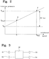
- a graph of the required rotation pressure increase as a function of the rotational speed is shown. As can be seen in the graph, there is a relationship between rotation pressure (and thereby rotational torque) and the rotational speed.
- p r0 denotes the no-load rotation pressure required to rotate the drill string when the drill bit is not in contact with the rock and is, among other, caused by friction in motor, gear box, etc.
- the point A denotes the rotation speed n full and rotation pressure p full that is determined for the exemplary drilling machine at the highest pressure used, e.g., 200 bar.
- this rotation pressure is greater than the rotation pressure p start that is available at start-up drilling, when the maximum feed pressure can not be used without risking that a problem with the direction/position of the hole arises. If thus n full is used during start-up drilling, there is a big risk that the joints are loosened with the above problem as result.
- the rotation speed is lowered to what is denoted by the point B in figure 2
- the drill string may be rotated using a rotation pressure/tightening torque that is sufficient to keep the joints together, since the required rotation pressure is lower than what is available.
- the difference between the no-load pressure and the rotation pressure at highest speed may be 20 bar. This pressure, however, is only exemplary and may, of course, be whatever is appropriate for the specific drilling equipment(s) wherein the present invention is to be implemented.
- the control system comprises a control unit 30 to which a sensor 31 for the rotation motor 7 pressure and a sensor for the drill string rotation speed may be connected.
- the rotation speed of the drill string may, e.g., be represented by the flow through the rotation motor or be obtained through direct measurement of the rotation of the drill string.
- the rotational speed may be represented by the voltage of the rotation motor.
- a certain voltage normally results in a certain rotational speed, which in turn results in a certain flow. By measuring the voltage the flow may thus be estimated, which has the advantage that a flow meter is not necessary for this purpose.
- the control unit 30 may further be arranged to control a number of valves 33, 34, which for example may control the flow through the rotation motor 7 and the feed pressure.
- the control unit may be arranged to provide values to a further control unit, which in turn controls various pressures.
- the control is performed by obtaining the current rotational speed and rotation pressure, e.g., by measurement, sensoring or monitoring.
- the measured rotation pressure is then compared with a predetermined relation between rotation pressure and rotational speed, as the one shown in the graph in figure 2 .
- the comparison may, e.g., be performed by a table look-up, in which is stored required rotation pressure for various rotational speeds. Based on the comparison, the flow through the rotation motor 7, and thereby rotational speed, may be controlled. Instead of using a table look-up, a mathematical relationship between rotational speed and required rotation pressure may be used to calculate required rotation pressure.
- control unit may increase the feed pressure to thereby increase the rotation pressure. If, on the other hand, the rotation pressure already is at a maximum, or if any feed pressure restriction is present, such as, e.g., during start-up drilling, the rotational speed may be lowered instead.
- the control unit may control the feed pressure either by directly controlling a valve 34 that controls flow and pressure to the feed motor/cylinder, or by providing values to a further control unit which in turn controls pressure/flow to the feed motor/cylinder.
- the available feed pressure is changing all the time, whereby the rotational speed may also be changing (increasing) all the time in accordance therewith.
- the present invention has been described above in connection with start-up drilling.
- the invention is also applicable at normal drilling. If, for example, the rock contains a lot of cracks or if the hardness of the rock varies substantially, situations may occur wherein the available tightening torque is not sufficient to ensure that the joints between drill bit/drill string components/drilling machine are kept together.
- the rotational speed is immediately decreased, so that the required tightening torque is decreased.
- the rotational speed may, at such an occasion, be reduced to precisely the rotational speed that corresponds to the available tightening torque.
- the present invention has been described above with reference to a specific kind of drilling machine.
- the invention may, of course, be used in other kinds of drilling machines, for example, drilling machines without damper and bushing.
Landscapes
- Life Sciences & Earth Sciences (AREA)
- Engineering & Computer Science (AREA)
- Geology (AREA)
- Mining & Mineral Resources (AREA)
- Physics & Mathematics (AREA)
- Environmental & Geological Engineering (AREA)
- Fluid Mechanics (AREA)
- General Life Sciences & Earth Sciences (AREA)
- Geochemistry & Mineralogy (AREA)
- Earth Drilling (AREA)
Claims (4)
- Agencement de régulation de paramètres de forage au cours d'un forage de roches, l'agencement étant conçu de sorte qu'un outil de forage (2) soit raccordable à une machine de forage (1) au moyen d'un ou de plusieurs composants de train de forage (3a, 3b), l'agencement comprenant des moyens d'entraînement en rotation de l'outil de forage (2) au cours du forage et de fourniture d'un couple de serrage destiné à serrer des raccords entre un ou plusieurs éléments dans le groupe constitué par : l'outil de forage (2), un ou plusieurs composants de train de forage (3a, 3b) et la machine de forage (1), l'agencement étant caractérisé en ce qu'il est conçu pour réguler la vitesse de rotation (n) de l'outil de forage (2) sur la base du couple de serrage disponible, lesdits moyens consistant en un moteur de rotation (7), l'agencement étant conçu en outre pour :- obtenir le couple de rotation disponible en fonction d'une pression de rotation,- obtenir, de façon continue et/ou à certains intervalles, la pression de rotation par utilisation de capteurs, par surveillance, par mesure ou par calcul, et- comparer la pression de rotation obtenue à la pression de rotation qui est exigée à la vitesse de rotation actuelle (n) de la machine de forage (1), et réduire la vitesse de rotation (n) de l'outil de forage (2) si la pression actuelle est inférieure à la pression exigée.
- Agencement selon la revendication 1, caractérisé en ce qu'il est conçu en outre pour réaliser la comparaison à l'aide d'une relation, par ex. mathématique, entre la pression de rotation exigée et la vitesse de rotation (n) de l'outil de forage (2) et/ou par consultation d'une table, ladite table comprenant une relation entre la pression de rotation exigée et la vitesse de rotation (n) de l'outil de forage (2).
- Procédé de régulation de paramètres de forage au cours d'un forage de roches, un outil de forage (2) étant raccordable à une machine de forage (1) au moyen d'un ou de plusieurs composants de train de forage (3a, 3b), l'outil de forage (2) étant entraîné en rotation au cours du forage et un couple de serrage étant fourni pour serrer des raccords entre un ou plusieurs éléments dans le groupe constitué par : l'outil de forage (2), un ou plusieurs composants de train de forage (3a, 3b) et la machine de forage (1), le procédé étant caractérisé par l'étape de régulation de la vitesse de rotation (n) de l'outil de forage (2) sur la base du couple de serrage disponible, le couple de rotation disponible étant obtenu en fonction d'une pression de rotation, le procédé comprenant en outre les étapes suivantes :- obtention, de façon continue et/ou à certains intervalles, de la pression de rotation par utilisation de capteurs, par surveillance, par mesure ou par calcul, et- comparaison de la pression de rotation obtenue à la pression de rotation qui est exigée à la vitesse de rotation actuelle (n) de la machine de forage (1), et réduction de la vitesse de rotation (n) de l'outil de forage (2) si la pression actuelle est inférieure à la pression exigée.
- Procédé selon la revendication 3, caractérisé par l'étape de réalisation de la comparaison à l'aide d'une relation, par ex. mathématique, entre la pression de rotation exigée et la vitesse de rotation (n) de l'outil de forage (2) et/ou par consultation d'une table comprenant une relation entre la pression de rotation exigée et la vitesse de rotation (n) de l'outil de forage (2).
Applications Claiming Priority (2)
| Application Number | Priority Date | Filing Date | Title |
|---|---|---|---|
| SE0403009A SE529230C2 (sv) | 2004-12-10 | 2004-12-10 | Anordning och metod vid borrning i berg |
| PCT/SE2005/001790 WO2006062460A1 (fr) | 2004-12-10 | 2005-11-29 | Systeme et procede destines a reguler les parametres de forage |
Publications (3)
| Publication Number | Publication Date |
|---|---|
| EP1819899A1 EP1819899A1 (fr) | 2007-08-22 |
| EP1819899A4 EP1819899A4 (fr) | 2014-11-19 |
| EP1819899B1 true EP1819899B1 (fr) | 2017-07-26 |
Family
ID=33550631
Family Applications (1)
| Application Number | Title | Priority Date | Filing Date |
|---|---|---|---|
| EP05804656.6A Active EP1819899B1 (fr) | 2004-12-10 | 2005-11-29 | Systeme et procede destines a reguler les parametres de forage |
Country Status (11)
| Country | Link |
|---|---|
| US (1) | US7762352B2 (fr) |
| EP (1) | EP1819899B1 (fr) |
| JP (1) | JP5011124B2 (fr) |
| CN (1) | CN101076654B (fr) |
| AU (1) | AU2005312383B2 (fr) |
| CA (1) | CA2583169C (fr) |
| ES (1) | ES2642092T3 (fr) |
| NO (1) | NO336944B1 (fr) |
| SE (1) | SE529230C2 (fr) |
| WO (1) | WO2006062460A1 (fr) |
| ZA (1) | ZA200704418B (fr) |
Families Citing this family (9)
| Publication number | Priority date | Publication date | Assignee | Title |
|---|---|---|---|---|
| FI123744B (fi) * | 2006-09-06 | 2013-10-15 | Sandvik Mining & Constr Oy | Menetelmä kallion poraamiseksi |
| SE532464C2 (sv) * | 2007-04-11 | 2010-01-26 | Atlas Copco Rock Drills Ab | Metod, anordning och bergborrningsrigg för styrning av åtminstone en borrparameter |
| SE532483C2 (sv) * | 2007-04-11 | 2010-02-02 | Atlas Copco Rock Drills Ab | Metod, anordning och bergborrningsrigg för styrning av åtminstone en borrparameter |
| SE533986C2 (sv) * | 2008-10-10 | 2011-03-22 | Atlas Copco Rock Drills Ab | Metod anordning och borrigg samt datoriserat styrsystem för att styra en bergborrmaskin vid borrning i berg |
| US8261855B2 (en) | 2009-11-11 | 2012-09-11 | Flanders Electric, Ltd. | Methods and systems for drilling boreholes |
| US20110108323A1 (en) * | 2009-11-11 | 2011-05-12 | Flanders Electric, Ltd. | Methods and systems for drilling boreholes |
| JP6438895B2 (ja) * | 2014-01-31 | 2018-12-19 | 古河ロックドリル株式会社 | さく孔機、及びオートスロットル制御用プログラム |
| US11448013B2 (en) * | 2018-12-05 | 2022-09-20 | Epiroc Drilling Solutions, Llc | Method and apparatus for percussion drilling |
| CN111636858A (zh) * | 2020-06-16 | 2020-09-08 | 中国铁建重工集团股份有限公司 | 一种防卡钎控制方法及系统 |
Family Cites Families (20)
| Publication number | Priority date | Publication date | Assignee | Title |
|---|---|---|---|---|
| US3581830A (en) * | 1969-09-03 | 1971-06-01 | Bucyrus Erie Co | Linear feed control for a rotary tool |
| US3670826A (en) * | 1970-09-11 | 1972-06-20 | Gardner Denver Co | Control system for drills |
| US4299294A (en) * | 1980-02-11 | 1981-11-10 | Aaa Products International, Inc. | Rotary tool with axial feed |
| SE8207405L (sv) * | 1982-12-27 | 1984-06-28 | Atlas Copco Ab | Bergborranordning och metod att optimera bergborrning |
| GB8411361D0 (en) * | 1984-05-03 | 1984-06-06 | Schlumberger Cambridge Researc | Assessment of drilling conditions |
| FI90276C (fi) | 1991-01-03 | 1994-01-10 | Tamrock Oy | Menetelmä reiän poraamiseksi kallioon |
| CN2122933U (zh) * | 1992-06-16 | 1992-11-25 | 华北石油管理局第二勘探公司 | 液压大钳扭矩控制器 |
| FR2713700B1 (fr) * | 1993-12-08 | 1996-03-15 | Inst Francais Du Petrole | Méthode et système de contrôle de la stabilité de la vitesse de rotation d'un outil de forage. |
| JP3447108B2 (ja) * | 1994-04-28 | 2003-09-16 | 古河機械金属株式会社 | さく孔機の回転制御装置 |
| US5449047A (en) * | 1994-09-07 | 1995-09-12 | Ingersoll-Rand Company | Automatic control of drilling system |
| WO1997049896A1 (fr) * | 1996-06-25 | 1997-12-31 | Tamrock Oy | Procede et dispositif servant a commander la perforation d'un rocher |
| FI105943B (fi) | 1996-06-25 | 2000-10-31 | Tamrock Oy | Menetelmä ja sovitelma kallioporakoneen syötön ohjaamiseksi |
| JPH10311193A (ja) * | 1997-05-09 | 1998-11-24 | Furukawa Co Ltd | さく孔制御装置 |
| FI105054B (fi) * | 1997-06-13 | 2000-05-31 | Tamrock Oy | Menetelmä kallionporauksen ohjaamiseksi |
| JP3488905B2 (ja) * | 1997-12-09 | 2004-01-19 | ヤマモトロックマシン株式会社 | 油圧式さく岩機の制御装置 |
| FI981707A0 (fi) * | 1998-08-06 | 1998-08-06 | Tamrock Oy | Sovitelma kallionporauksen ohjaamiseksi |
| JP2000119715A (ja) * | 1998-10-06 | 2000-04-25 | Yamamoto Lock Machine Kk | 油圧式開孔機 |
| SE515204C2 (sv) | 1999-11-03 | 2001-06-25 | Atlas Copco Rock Drills Ab | Förfarande och anordning för styrning av en bergborrmaskin |
| FI115553B (fi) * | 2001-05-15 | 2005-05-31 | Sandvik Tamrock Oy | Järjestely porauksen ohjaukseen |
| SE520421C2 (sv) | 2001-11-22 | 2003-07-08 | Atlas Copco Rock Drills Ab | Förfarande för bergborrning |
-
2004
- 2004-12-10 SE SE0403009A patent/SE529230C2/sv unknown
-
2005
- 2005-11-29 CA CA2583169A patent/CA2583169C/fr active Active
- 2005-11-29 WO PCT/SE2005/001790 patent/WO2006062460A1/fr active Application Filing
- 2005-11-29 ES ES05804656.6T patent/ES2642092T3/es active Active
- 2005-11-29 EP EP05804656.6A patent/EP1819899B1/fr active Active
- 2005-11-29 CN CN2005800394680A patent/CN101076654B/zh active Active
- 2005-11-29 ZA ZA200704418A patent/ZA200704418B/xx unknown
- 2005-11-29 JP JP2007545412A patent/JP5011124B2/ja active Active
- 2005-11-29 US US11/665,724 patent/US7762352B2/en active Active
- 2005-11-29 AU AU2005312383A patent/AU2005312383B2/en active Active
-
2007
- 2007-07-09 NO NO20073545A patent/NO336944B1/no not_active IP Right Cessation
Non-Patent Citations (1)
| Title |
|---|
| None * |
Also Published As
| Publication number | Publication date |
|---|---|
| CA2583169A1 (fr) | 2006-06-15 |
| CA2583169C (fr) | 2013-08-20 |
| AU2005312383A2 (en) | 2006-06-15 |
| EP1819899A1 (fr) | 2007-08-22 |
| US7762352B2 (en) | 2010-07-27 |
| WO2006062460A8 (fr) | 2007-05-03 |
| ES2642092T3 (es) | 2017-11-15 |
| EP1819899A4 (fr) | 2014-11-19 |
| ZA200704418B (en) | 2008-08-27 |
| AU2005312383A1 (en) | 2006-06-15 |
| SE0403009D0 (sv) | 2004-12-10 |
| JP2008523279A (ja) | 2008-07-03 |
| WO2006062460A1 (fr) | 2006-06-15 |
| CN101076654B (zh) | 2011-03-30 |
| SE0403009L (sv) | 2006-06-11 |
| AU2005312383B2 (en) | 2010-10-07 |
| NO20073545L (no) | 2007-09-06 |
| US20090044976A1 (en) | 2009-02-19 |
| CN101076654A (zh) | 2007-11-21 |
| NO336944B1 (no) | 2015-11-30 |
| JP5011124B2 (ja) | 2012-08-29 |
| SE529230C2 (sv) | 2007-06-05 |
Similar Documents
| Publication | Publication Date | Title |
|---|---|---|
| EP1819899B1 (fr) | Systeme et procede destines a reguler les parametres de forage | |
| EP2173959B1 (fr) | Procédé et dispositif de commande d'une installation de forage de roche | |
| EP2342421B1 (fr) | Procédé et disposition de commande de perforatrice | |
| JP4116565B2 (ja) | 削岩装置運転制御方法および運転制御機器 | |
| EP1436486B1 (fr) | Procede et agencement de commande du forage par percussion, se basant sur le degre de contrainte determine a partir de la mesure du taux d'entrainement | |
| SE532483C2 (sv) | Metod, anordning och bergborrningsrigg för styrning av åtminstone en borrparameter | |
| US7198117B2 (en) | Method and arrangement for controlling percussion rock drilling | |
| KR101834974B1 (ko) | 전동 공구의 제어 방법 | |
| IE914082A1 (en) | Drill steel | |
| JP2005113612A (ja) | 回転圧入鋼管杭の施工管理方法 | |
| AU2002333928B2 (en) | Method and arrangement of controlling of percussive drilling based on the stress level determined from the measured feed rate | |
| WO2023234819A1 (fr) | Procédé de réglage en temps réel d'au moins un paramètre de forage pendant un forage de roche par une machine de forage | |
| WO2002035062A1 (fr) | Procede de perforation au rocher | |
| AU2002333928A1 (en) | Method and arrangement of controlling of percussive drilling based on the stress level determined from the measured feed rate | |
| WO2002048505A1 (fr) | Dispositif et procede de forage presentant un taux de penetration optimise |
Legal Events
| Date | Code | Title | Description |
|---|---|---|---|
| PUAI | Public reference made under article 153(3) epc to a published international application that has entered the european phase |
Free format text: ORIGINAL CODE: 0009012 |
|
| 17P | Request for examination filed |
Effective date: 20070612 |
|
| AK | Designated contracting states |
Kind code of ref document: A1 Designated state(s): AT BE BG CH CY CZ DE DK EE ES FI FR GB GR HU IE IS IT LI LT LU LV MC NL PL PT RO SE SI SK TR |
|
| DAX | Request for extension of the european patent (deleted) | ||
| RIC1 | Information provided on ipc code assigned before grant |
Ipc: E21B 44/00 20060101AFI20141009BHEP |
|
| A4 | Supplementary search report drawn up and despatched |
Effective date: 20141017 |
|
| 17Q | First examination report despatched |
Effective date: 20150907 |
|
| GRAP | Despatch of communication of intention to grant a patent |
Free format text: ORIGINAL CODE: EPIDOSNIGR1 |
|
| INTG | Intention to grant announced |
Effective date: 20170413 |
|
| RIN1 | Information on inventor provided before grant (corrected) |
Inventor name: PETTERSSON, MARIA |
|
| GRAS | Grant fee paid |
Free format text: ORIGINAL CODE: EPIDOSNIGR3 |
|
| GRAA | (expected) grant |
Free format text: ORIGINAL CODE: 0009210 |
|
| AK | Designated contracting states |
Kind code of ref document: B1 Designated state(s): AT BE BG CH CY CZ DE DK EE ES FI FR GB GR HU IE IS IT LI LT LU LV MC NL PL PT RO SE SI SK TR |
|
| REG | Reference to a national code |
Ref country code: GB Ref legal event code: FG4D Ref country code: DE Ref legal event code: R081 Ref document number: 602005052419 Country of ref document: DE Owner name: EPIROC ROCK DRILLS AKTIEBOLAG, SE Free format text: FORMER OWNER: ATLAS COPCO ROCK DRILLS AB, OREBRO, SE |
|
| REG | Reference to a national code |
Ref country code: CH Ref legal event code: EP |
|
| REG | Reference to a national code |
Ref country code: AT Ref legal event code: REF Ref document number: 912567 Country of ref document: AT Kind code of ref document: T Effective date: 20170815 |
|
| REG | Reference to a national code |
Ref country code: IE Ref legal event code: FG4D |
|
| REG | Reference to a national code |
Ref country code: DE Ref legal event code: R096 Ref document number: 602005052419 Country of ref document: DE |
|
| REG | Reference to a national code |
Ref country code: ES Ref legal event code: FG2A Ref document number: 2642092 Country of ref document: ES Kind code of ref document: T3 Effective date: 20171115 |
|
| REG | Reference to a national code |
Ref country code: FR Ref legal event code: PLFP Year of fee payment: 13 |
|
| REG | Reference to a national code |
Ref country code: NL Ref legal event code: MP Effective date: 20170726 |
|
| REG | Reference to a national code |
Ref country code: LT Ref legal event code: MG4D |
|
| PG25 | Lapsed in a contracting state [announced via postgrant information from national office to epo] |
Ref country code: SE Free format text: LAPSE BECAUSE OF FAILURE TO SUBMIT A TRANSLATION OF THE DESCRIPTION OR TO PAY THE FEE WITHIN THE PRESCRIBED TIME-LIMIT Effective date: 20170726 Ref country code: LT Free format text: LAPSE BECAUSE OF FAILURE TO SUBMIT A TRANSLATION OF THE DESCRIPTION OR TO PAY THE FEE WITHIN THE PRESCRIBED TIME-LIMIT Effective date: 20170726 Ref country code: NL Free format text: LAPSE BECAUSE OF FAILURE TO SUBMIT A TRANSLATION OF THE DESCRIPTION OR TO PAY THE FEE WITHIN THE PRESCRIBED TIME-LIMIT Effective date: 20170726 |
|
| PG25 | Lapsed in a contracting state [announced via postgrant information from national office to epo] |
Ref country code: IS Free format text: LAPSE BECAUSE OF FAILURE TO SUBMIT A TRANSLATION OF THE DESCRIPTION OR TO PAY THE FEE WITHIN THE PRESCRIBED TIME-LIMIT Effective date: 20171126 Ref country code: GR Free format text: LAPSE BECAUSE OF FAILURE TO SUBMIT A TRANSLATION OF THE DESCRIPTION OR TO PAY THE FEE WITHIN THE PRESCRIBED TIME-LIMIT Effective date: 20171027 Ref country code: BG Free format text: LAPSE BECAUSE OF FAILURE TO SUBMIT A TRANSLATION OF THE DESCRIPTION OR TO PAY THE FEE WITHIN THE PRESCRIBED TIME-LIMIT Effective date: 20171026 Ref country code: PL Free format text: LAPSE BECAUSE OF FAILURE TO SUBMIT A TRANSLATION OF THE DESCRIPTION OR TO PAY THE FEE WITHIN THE PRESCRIBED TIME-LIMIT Effective date: 20170726 Ref country code: LV Free format text: LAPSE BECAUSE OF FAILURE TO SUBMIT A TRANSLATION OF THE DESCRIPTION OR TO PAY THE FEE WITHIN THE PRESCRIBED TIME-LIMIT Effective date: 20170726 |
|
| REG | Reference to a national code |
Ref country code: ES Ref legal event code: PC2A Owner name: EPIROC ROCK DRILLS AKTIEBOLAG Effective date: 20180319 |
|
| PG25 | Lapsed in a contracting state [announced via postgrant information from national office to epo] |
Ref country code: CZ Free format text: LAPSE BECAUSE OF FAILURE TO SUBMIT A TRANSLATION OF THE DESCRIPTION OR TO PAY THE FEE WITHIN THE PRESCRIBED TIME-LIMIT Effective date: 20170726 Ref country code: RO Free format text: LAPSE BECAUSE OF FAILURE TO SUBMIT A TRANSLATION OF THE DESCRIPTION OR TO PAY THE FEE WITHIN THE PRESCRIBED TIME-LIMIT Effective date: 20170726 Ref country code: DK Free format text: LAPSE BECAUSE OF FAILURE TO SUBMIT A TRANSLATION OF THE DESCRIPTION OR TO PAY THE FEE WITHIN THE PRESCRIBED TIME-LIMIT Effective date: 20170726 |
|
| REG | Reference to a national code |
Ref country code: DE Ref legal event code: R097 Ref document number: 602005052419 Country of ref document: DE |
|
| REG | Reference to a national code |
Ref country code: AT Ref legal event code: HC Ref document number: 912567 Country of ref document: AT Kind code of ref document: T Owner name: EPIROC ROCK DRILLS AKTIEBOLAG, SE Effective date: 20180326 |
|
| PG25 | Lapsed in a contracting state [announced via postgrant information from national office to epo] |
Ref country code: SK Free format text: LAPSE BECAUSE OF FAILURE TO SUBMIT A TRANSLATION OF THE DESCRIPTION OR TO PAY THE FEE WITHIN THE PRESCRIBED TIME-LIMIT Effective date: 20170726 Ref country code: EE Free format text: LAPSE BECAUSE OF FAILURE TO SUBMIT A TRANSLATION OF THE DESCRIPTION OR TO PAY THE FEE WITHIN THE PRESCRIBED TIME-LIMIT Effective date: 20170726 |
|
| PLBE | No opposition filed within time limit |
Free format text: ORIGINAL CODE: 0009261 |
|
| STAA | Information on the status of an ep patent application or granted ep patent |
Free format text: STATUS: NO OPPOSITION FILED WITHIN TIME LIMIT |
|
| PG25 | Lapsed in a contracting state [announced via postgrant information from national office to epo] |
Ref country code: MC Free format text: LAPSE BECAUSE OF FAILURE TO SUBMIT A TRANSLATION OF THE DESCRIPTION OR TO PAY THE FEE WITHIN THE PRESCRIBED TIME-LIMIT Effective date: 20170726 |
|
| 26N | No opposition filed |
Effective date: 20180430 |
|
| PG25 | Lapsed in a contracting state [announced via postgrant information from national office to epo] |
Ref country code: LI Free format text: LAPSE BECAUSE OF NON-PAYMENT OF DUE FEES Effective date: 20171130 Ref country code: CH Free format text: LAPSE BECAUSE OF NON-PAYMENT OF DUE FEES Effective date: 20171130 |
|
| PG25 | Lapsed in a contracting state [announced via postgrant information from national office to epo] |
Ref country code: SI Free format text: LAPSE BECAUSE OF FAILURE TO SUBMIT A TRANSLATION OF THE DESCRIPTION OR TO PAY THE FEE WITHIN THE PRESCRIBED TIME-LIMIT Effective date: 20170726 Ref country code: LU Free format text: LAPSE BECAUSE OF NON-PAYMENT OF DUE FEES Effective date: 20171129 |
|
| REG | Reference to a national code |
Ref country code: BE Ref legal event code: MM Effective date: 20171130 |
|
| REG | Reference to a national code |
Ref country code: DE Ref legal event code: R081 Ref document number: 602005052419 Country of ref document: DE Owner name: EPIROC ROCK DRILLS AKTIEBOLAG, SE Free format text: FORMER OWNER: ATLAS COPCO ROCK DRILLS AB, OEREBRO, SE |
|
| PG25 | Lapsed in a contracting state [announced via postgrant information from national office to epo] |
Ref country code: BE Free format text: LAPSE BECAUSE OF NON-PAYMENT OF DUE FEES Effective date: 20171130 |
|
| REG | Reference to a national code |
Ref country code: FR Ref legal event code: CD Owner name: EPIROC ROCK DRILLS AKTIEBOLAG, SE Effective date: 20181107 |
|
| PGFP | Annual fee paid to national office [announced via postgrant information from national office to epo] |
Ref country code: IE Payment date: 20181126 Year of fee payment: 14 |
|
| PGFP | Annual fee paid to national office [announced via postgrant information from national office to epo] |
Ref country code: ES Payment date: 20181203 Year of fee payment: 14 |
|
| PG25 | Lapsed in a contracting state [announced via postgrant information from national office to epo] |
Ref country code: HU Free format text: LAPSE BECAUSE OF FAILURE TO SUBMIT A TRANSLATION OF THE DESCRIPTION OR TO PAY THE FEE WITHIN THE PRESCRIBED TIME-LIMIT; INVALID AB INITIO Effective date: 20051129 |
|
| PG25 | Lapsed in a contracting state [announced via postgrant information from national office to epo] |
Ref country code: CY Free format text: LAPSE BECAUSE OF NON-PAYMENT OF DUE FEES Effective date: 20170726 |
|
| PGFP | Annual fee paid to national office [announced via postgrant information from national office to epo] |
Ref country code: IT Payment date: 20191125 Year of fee payment: 15 |
|
| PG25 | Lapsed in a contracting state [announced via postgrant information from national office to epo] |
Ref country code: TR Free format text: LAPSE BECAUSE OF FAILURE TO SUBMIT A TRANSLATION OF THE DESCRIPTION OR TO PAY THE FEE WITHIN THE PRESCRIBED TIME-LIMIT Effective date: 20170726 |
|
| PGFP | Annual fee paid to national office [announced via postgrant information from national office to epo] |
Ref country code: AT Payment date: 20191104 Year of fee payment: 15 |
|
| PG25 | Lapsed in a contracting state [announced via postgrant information from national office to epo] |
Ref country code: PT Free format text: LAPSE BECAUSE OF FAILURE TO SUBMIT A TRANSLATION OF THE DESCRIPTION OR TO PAY THE FEE WITHIN THE PRESCRIBED TIME-LIMIT Effective date: 20170726 |
|
| REG | Reference to a national code |
Ref country code: DE Ref legal event code: R119 Ref document number: 602005052419 Country of ref document: DE |
|
| GBPC | Gb: european patent ceased through non-payment of renewal fee |
Effective date: 20191129 |
|
| PG25 | Lapsed in a contracting state [announced via postgrant information from national office to epo] |
Ref country code: IE Free format text: LAPSE BECAUSE OF NON-PAYMENT OF DUE FEES Effective date: 20191129 Ref country code: GB Free format text: LAPSE BECAUSE OF NON-PAYMENT OF DUE FEES Effective date: 20191129 Ref country code: DE Free format text: LAPSE BECAUSE OF NON-PAYMENT OF DUE FEES Effective date: 20200603 |
|
| REG | Reference to a national code |
Ref country code: ES Ref legal event code: FD2A Effective date: 20210527 |
|
| REG | Reference to a national code |
Ref country code: AT Ref legal event code: MM01 Ref document number: 912567 Country of ref document: AT Kind code of ref document: T Effective date: 20201129 |
|
| PG25 | Lapsed in a contracting state [announced via postgrant information from national office to epo] |
Ref country code: AT Free format text: LAPSE BECAUSE OF NON-PAYMENT OF DUE FEES Effective date: 20201129 Ref country code: ES Free format text: LAPSE BECAUSE OF NON-PAYMENT OF DUE FEES Effective date: 20191130 |
|
| PG25 | Lapsed in a contracting state [announced via postgrant information from national office to epo] |
Ref country code: IT Free format text: LAPSE BECAUSE OF NON-PAYMENT OF DUE FEES Effective date: 20201129 |
|
| PGFP | Annual fee paid to national office [announced via postgrant information from national office to epo] |
Ref country code: FR Payment date: 20221123 Year of fee payment: 18 |
|
| PGFP | Annual fee paid to national office [announced via postgrant information from national office to epo] |
Ref country code: FI Payment date: 20231019 Year of fee payment: 19 |