EP1818532B1 - Dispositif destiné à la réinjection de gaz d'échappement - Google Patents
Dispositif destiné à la réinjection de gaz d'échappement Download PDFInfo
- Publication number
- EP1818532B1 EP1818532B1 EP07000309A EP07000309A EP1818532B1 EP 1818532 B1 EP1818532 B1 EP 1818532B1 EP 07000309 A EP07000309 A EP 07000309A EP 07000309 A EP07000309 A EP 07000309A EP 1818532 B1 EP1818532 B1 EP 1818532B1
- Authority
- EP
- European Patent Office
- Prior art keywords
- air
- exhaust gas
- compressed
- gas recirculation
- charge
- Prior art date
- Legal status (The legal status is an assumption and is not a legal conclusion. Google has not performed a legal analysis and makes no representation as to the accuracy of the status listed.)
- Active
Links
- 238000002485 combustion reaction Methods 0.000 claims abstract description 31
- 238000000034 method Methods 0.000 description 3
- 230000000903 blocking effect Effects 0.000 description 2
- 238000010276 construction Methods 0.000 description 2
- 230000001276 controlling effect Effects 0.000 description 2
- 238000001816 cooling Methods 0.000 description 2
- 239000003344 environmental pollutant Substances 0.000 description 2
- 238000000605 extraction Methods 0.000 description 2
- 231100000719 pollutant Toxicity 0.000 description 2
- 230000001419 dependent effect Effects 0.000 description 1
- 238000011161 development Methods 0.000 description 1
- 230000018109 developmental process Effects 0.000 description 1
- 230000002349 favourable effect Effects 0.000 description 1
- 238000002156 mixing Methods 0.000 description 1
- 230000001105 regulatory effect Effects 0.000 description 1
Images
Classifications
-
- F—MECHANICAL ENGINEERING; LIGHTING; HEATING; WEAPONS; BLASTING
- F02—COMBUSTION ENGINES; HOT-GAS OR COMBUSTION-PRODUCT ENGINE PLANTS
- F02B—INTERNAL-COMBUSTION PISTON ENGINES; COMBUSTION ENGINES IN GENERAL
- F02B21/00—Engines characterised by air-storage chambers
-
- F—MECHANICAL ENGINEERING; LIGHTING; HEATING; WEAPONS; BLASTING
- F02—COMBUSTION ENGINES; HOT-GAS OR COMBUSTION-PRODUCT ENGINE PLANTS
- F02M—SUPPLYING COMBUSTION ENGINES IN GENERAL WITH COMBUSTIBLE MIXTURES OR CONSTITUENTS THEREOF
- F02M26/00—Engine-pertinent apparatus for adding exhaust gases to combustion-air, main fuel or fuel-air mixture, e.g. by exhaust gas recirculation [EGR] systems
- F02M26/02—EGR systems specially adapted for supercharged engines
- F02M26/04—EGR systems specially adapted for supercharged engines with a single turbocharger
- F02M26/05—High pressure loops, i.e. wherein recirculated exhaust gas is taken out from the exhaust system upstream of the turbine and reintroduced into the intake system downstream of the compressor
-
- F—MECHANICAL ENGINEERING; LIGHTING; HEATING; WEAPONS; BLASTING
- F02—COMBUSTION ENGINES; HOT-GAS OR COMBUSTION-PRODUCT ENGINE PLANTS
- F02M—SUPPLYING COMBUSTION ENGINES IN GENERAL WITH COMBUSTIBLE MIXTURES OR CONSTITUENTS THEREOF
- F02M26/00—Engine-pertinent apparatus for adding exhaust gases to combustion-air, main fuel or fuel-air mixture, e.g. by exhaust gas recirculation [EGR] systems
- F02M26/52—Systems for actuating EGR valves
- F02M26/59—Systems for actuating EGR valves using positive pressure actuators; Check valves therefor
- F02M26/60—Systems for actuating EGR valves using positive pressure actuators; Check valves therefor in response to air intake pressure
-
- F—MECHANICAL ENGINEERING; LIGHTING; HEATING; WEAPONS; BLASTING
- F02—COMBUSTION ENGINES; HOT-GAS OR COMBUSTION-PRODUCT ENGINE PLANTS
- F02B—INTERNAL-COMBUSTION PISTON ENGINES; COMBUSTION ENGINES IN GENERAL
- F02B29/00—Engines characterised by provision for charging or scavenging not provided for in groups F02B25/00, F02B27/00 or F02B33/00 - F02B39/00; Details thereof
- F02B29/04—Cooling of air intake supply
- F02B29/0406—Layout of the intake air cooling or coolant circuit
-
- F—MECHANICAL ENGINEERING; LIGHTING; HEATING; WEAPONS; BLASTING
- F02—COMBUSTION ENGINES; HOT-GAS OR COMBUSTION-PRODUCT ENGINE PLANTS
- F02B—INTERNAL-COMBUSTION PISTON ENGINES; COMBUSTION ENGINES IN GENERAL
- F02B37/00—Engines characterised by provision of pumps driven at least for part of the time by exhaust
-
- F—MECHANICAL ENGINEERING; LIGHTING; HEATING; WEAPONS; BLASTING
- F02—COMBUSTION ENGINES; HOT-GAS OR COMBUSTION-PRODUCT ENGINE PLANTS
- F02M—SUPPLYING COMBUSTION ENGINES IN GENERAL WITH COMBUSTIBLE MIXTURES OR CONSTITUENTS THEREOF
- F02M26/00—Engine-pertinent apparatus for adding exhaust gases to combustion-air, main fuel or fuel-air mixture, e.g. by exhaust gas recirculation [EGR] systems
- F02M26/02—EGR systems specially adapted for supercharged engines
- F02M26/08—EGR systems specially adapted for supercharged engines for engines having two or more intake charge compressors or exhaust gas turbines, e.g. a turbocharger combined with an additional compressor
-
- F—MECHANICAL ENGINEERING; LIGHTING; HEATING; WEAPONS; BLASTING
- F02—COMBUSTION ENGINES; HOT-GAS OR COMBUSTION-PRODUCT ENGINE PLANTS
- F02M—SUPPLYING COMBUSTION ENGINES IN GENERAL WITH COMBUSTIBLE MIXTURES OR CONSTITUENTS THEREOF
- F02M26/00—Engine-pertinent apparatus for adding exhaust gases to combustion-air, main fuel or fuel-air mixture, e.g. by exhaust gas recirculation [EGR] systems
- F02M26/13—Arrangement or layout of EGR passages, e.g. in relation to specific engine parts or for incorporation of accessories
- F02M26/22—Arrangement or layout of EGR passages, e.g. in relation to specific engine parts or for incorporation of accessories with coolers in the recirculation passage
- F02M26/23—Layout, e.g. schematics
Definitions
- the invention relates to an arrangement for exhaust gas recirculation in supercharged by exhaust gas turbocharged internal combustion engine according to the preamble of claim 1.
- turbocharger arrangements for increasing the power in order to supply the combustion chambers with compressed air in order to achieve better cylinder filling.
- JP 2004 011562 A It is proposed to provide downstream of a compressed air reservoir a connecting line to the intake manifold. However, this is only intended for feeding compressed air into the intake manifold and not for feeding the compressed air reservoir with compressed charge air.
- the invention is based on the consideration that with the device for charging the internal combustion engine, a source of compressed air is in principle present, it is therefore proposed to branch off from the compressed charge air stream by means of a Druck Kunststoffentglazed Gustav compressed air and a charge air check valve in a compressed air reservoir respectively.
- the output of the compressed air reservoir is connected to the input of a the compressed air switching power-driven control valve connected so that its switched output acts on the actuating cylinder of the Abgas Wegflihrventils with appropriate switching position and triggers switching operations of the exhaust gas recirculation valve.
- the actuating cylinder is designed for the comparatively low pressure which the compressor of the turbocharger is able to deliver.
- the branch of the charge air flow in the compressed air reservoir is advantageously arranged after the intercooler, so that already passes relatively cool air in the compressed air reservoir.
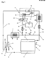
- FIG. 1 denotes a schematic representation of an exhaust gas turbocharger supercharged internal combustion engine with exhaust gas recirculation.
- an internal combustion engine 1 is acted upon by its exhaust gas flow 2, which flows out via the exhaust manifold 3, the turbine 4 of an exhaust gas turbocharger 5.
- the turbine 4 drives via a mechanical connection the compressor 6 of the exhaust gas turbocharger 5, which via an air filter (not shown) Fresh air sucks and compacts.
- the polluted air passes, as usual in such arrangements, via a charge air cooler 7 to the intake manifold 8 of the internal combustion engine 1.
- the exhaust gas stream at a point 9 which is downstream of the turbine 4 of the exhaust gas turbocharger, exhaust gas removed and by means of an exhaust gas recirculation line 10th , 10 'returned to the suction side of the internal combustion engine.
- the amount of exhaust gas to be recirculated is regulated by means of an exhaust gas recirculation valve 11, whose function will be discussed later, as a function of the operating parameters of the internal combustion engine 1.
- the exhaust gas that passes through the exhaust gas recirculation valve 11, passes through a so-called EGR cooler 12, which cools the recirculated exhaust gas strong, and a check valve 13, which is also referred to as flutter valve, at the mixing point 14 in the compressed charge air and from there together with this to the intake manifold 8 of the internal combustion engine.
- the object of the check valve 13 is to allow exhaust gas pressure peaks to pass when the exhaust gas recirculation valve is open, but to prevent overflow of the charge air into the exhaust gas tract when the pressure of the charge air is higher than the exhaust gas pressure in the exhaust gas recirculation line 10 '.
- an exhaust gas recirculation valve 11 is used, which, depending on the operating parameters of the internal combustion engine 1, exhaust gas through the exhaust gas recirculation line 10, 10 'happen.
- the actuating mechanism of the exhaust gas recirculation valve 11 consists of a pressurized air actuated actuator cylinder 15 which actuates a locking member 16 in the exhaust gas recirculation line 10 via a mechanical operative connection.
- the blocking member 16 may be an exhaust flap in the exhaust gas recirculation line 10, which is pivotable by means of the actuating cylinder 15 via a mechanical linkage along the arrows 17 and thus, depending on the actuation of the actuating cylinder 15, the exhaust gas recirculation line 10 opens or closes ,
- the exhaust gas recirculation valve 11 may be arranged in front of the EGR cooler 12, as is the case in the example. This arrangement requires that, due to the relatively high temperatures at this point of the exhaust gas recirculation line 10, for driving the exhaust gas recirculation valve 11, a cylinder subjected to compressed air is far more reliable than e.g. an electric or a hydraulic drive.
- a Druckluftentddling Arthur 19 is provided, which branches off from the compressed charge air leading charge air tube 18 and leads via a charge air check valve 20 to a compressed air reservoir 21.
- the output 22 of the compressed air reservoir 21 is connected to the input 23 of the control valve 24, which is designed as a solenoid valve, whose switched output 25 in turn acts on the actuating cylinder 15.
- the branch of the compressed air extraction line 19 is located downstream of the intercooler 7, because the discharged therefrom in the compressed air reservoir 21 compressed air is already cooled, whereby a pressure loss due to cooling in the compressed air reservoir is largely avoided.
- the pressure in the charge air pipe can be evaluated by means of a boost pressure sensor 26 of the engine control unit. If the charge pressure is too low, insufficient compressed air would be supplied, so that switching operations of the exhaust gas recirculation valve 11 below a predetermined pressure level in the charge air pipe 18 are to be suppressed. This procedure is favorable when a boost pressure sensor 26 in the charge air pipe 18 already exists for controlling other processes anyway.
- Another indirect way to ensure the presence of a sufficient pressure level in the compressed air reservoir 21 is to allow switching operations only from a predetermined, empirically determined engine speed at which the compressor 6 of the turbocharger 5 provides a corresponding pressure level.
- the speed is detected by an existing anyway in internal combustion engines of the type in question speed sensor 27 and evaluated by a likewise existing engine control unit (not shown), so that no additional effort is necessary.
- the advantage of the arrangement according to the invention described above consists primarily in the fact that on the one hand compressed air can be used as the drive medium for the exhaust gas recirculation valve 11, which improves the reliability especially when arranged on the hot side of the internal combustion engine exhaust gas recirculation valve.
- compressed air can be used as the drive medium for the exhaust gas recirculation valve 11, which improves the reliability especially when arranged on the hot side of the internal combustion engine exhaust gas recirculation valve.
- the compressed charge air as a drive medium for the exhaust gas recirculation valve, the use of an additional compressed air generating device unnecessary, so that even in those applications in which a compressed air system with its own pressure generator is not available, such.
- an operated by compressed air exhaust gas recirculation valve can be realized with minimal effort.
Landscapes
- Engineering & Computer Science (AREA)
- Chemical & Material Sciences (AREA)
- Combustion & Propulsion (AREA)
- Mechanical Engineering (AREA)
- General Engineering & Computer Science (AREA)
- Exhaust-Gas Circulating Devices (AREA)
- Supercharger (AREA)
Claims (6)
- Dispositif de recyclage des gaz d'échappement d'un moteur à combustion interne suralimenté par un turbocompresseur de gaz d'échappement dans lequel- la veine de gaz d'échappement (2) sortant du moteur à combustion interne (1) entraîne la turbine (4) du turbocompresseur de gaz d'échappement (5),- le compresseur (6) du turbocompresseur de gaz d'échappement (5) comprime l'air frais alimentant le moteur à combustion interne (1),- en amont de la turbine (5), une conduite de recyclage des gaz d'échappement (10) dérivant de la veine des gaz d'échappement (2) et comportant au moins un radiateur des gaz d'échappement (12) pour les gaz d'échappement à recycler et au moins une soupape de recyclage des gaz d'échappement (11) actionnée par de l'air comprimé et régulant la quantité de gaz d'échappement à recycler,- l'air frais comprimé par le compresseur (6) alimente le moteur à combustion interne en traversant au moins un radiateur d'air d'alimentation (7) avant d'arriver dans le collecteur d'admission (8),- la conduite de recyclage de gaz d'échappement (10') en aval de la soupape de recyclage de gaz d'échappement (11) débouche en aval du radiateur d'air d'alimentation (7) dans la veine d'air d'alimentation,dispositif caractérisé en ce que- une conduite de prélèvement d'air comprimé (19) dérive de la veine d'air d'alimentation, comprimé, cette conduite arrivant à travers un clapet anti-retour d'air d'alimentation (20) dans un réservoir d'air comprimé (21),- la sortie (22) du réservoir d'alimentation en air comprimé (21) est reliée à l'entrée (23) d'une soupape de commande (24) motorisée, commutant l'air comprimé,- la sortie commutée (25) de la soupape de commande (24) motorisée, sollicite avec de l'air comprimé la soupape (11), entraînée, de recyclage des gaz d'échappement.
- Dispositif selon la revendication 1,
caractérisé en ce que
le point où la conduite de prélèvement d'air comprimé (19) dérive de la conduite d'alimentation en air (18) pour la veine d'air d'alimentation se situe entre le radiateur d'air d'alimentation (7) et l'embouchure de la conduite de recyclage des gaz d'échappement (10') dans la veine d'air d'alimentation. - Dispositif selon l'une des revendications précédentes,
caractérisé par
un capteur qui détermine directement ou indirectement à l'aide d'une unité de commande de moteur, l'établissement d'un niveau de pression prédéterminé dans le réservoir d'alimentation en air comprimé (21). - Dispositif selon la revendication 3,
caractérisé en ce que
le capteur est un capteur de pression d'alimentation (26) installé dans la conduite d'alimentation en air. - Dispositif selon la revendication 3,
caractérisé en ce que
le capteur est un capteur de vitesse de rotation (27) détectant la vitesse de rotation (régime) du moteur à combustion interne (1). - Dispositif selon la revendication 3,
caractérisé en ce que
le capteur est un capteur de pression (28) installé dans le réservoir d'alimentation en air comprimé (21).
Priority Applications (1)
| Application Number | Priority Date | Filing Date | Title |
|---|---|---|---|
| PL07000309T PL1818532T3 (pl) | 2006-02-10 | 2007-01-09 | Układ do recyrkulacji spalin |
Applications Claiming Priority (1)
| Application Number | Priority Date | Filing Date | Title |
|---|---|---|---|
| DE102006006147A DE102006006147A1 (de) | 2006-02-10 | 2006-02-10 | Anordnung zur Abgasrückführung |
Publications (3)
| Publication Number | Publication Date |
|---|---|
| EP1818532A2 EP1818532A2 (fr) | 2007-08-15 |
| EP1818532A3 EP1818532A3 (fr) | 2010-05-26 |
| EP1818532B1 true EP1818532B1 (fr) | 2011-06-29 |
Family
ID=37890301
Family Applications (1)
| Application Number | Title | Priority Date | Filing Date |
|---|---|---|---|
| EP07000309A Active EP1818532B1 (fr) | 2006-02-10 | 2007-01-09 | Dispositif destiné à la réinjection de gaz d'échappement |
Country Status (4)
| Country | Link |
|---|---|
| EP (1) | EP1818532B1 (fr) |
| AT (1) | ATE514851T1 (fr) |
| DE (1) | DE102006006147A1 (fr) |
| PL (1) | PL1818532T3 (fr) |
Families Citing this family (2)
| Publication number | Priority date | Publication date | Assignee | Title |
|---|---|---|---|---|
| DE102010047821A1 (de) * | 2010-10-07 | 2012-04-12 | Daimler Ag | Luftverdichtungseinrichtung für einen Kraftwagen sowie Verfahren zum Betreiben einer solchen Luftverdichtungseinrichtung |
| CN111720841A (zh) * | 2020-06-24 | 2020-09-29 | 北京市环境保护科学研究院 | 高效净化烤鸭制作过程中产生的vocs的系统和方法 |
Family Cites Families (6)
| Publication number | Priority date | Publication date | Assignee | Title |
|---|---|---|---|---|
| JPH0417765A (ja) | 1990-05-08 | 1992-01-22 | Toyota Motor Corp | 直列2段過給内燃機関の排気ガス再循環装置 |
| JPH08240155A (ja) * | 1995-03-03 | 1996-09-17 | Hino Motors Ltd | Egr制御装置 |
| JP2000064912A (ja) * | 1998-08-24 | 2000-03-03 | Isuzu Motors Ltd | Egr装置 |
| JP2001329879A (ja) * | 2000-05-24 | 2001-11-30 | Nissan Diesel Motor Co Ltd | 内燃機関の排気還流装置 |
| US6598396B2 (en) * | 2001-11-16 | 2003-07-29 | Caterpillar Inc | Internal combustion engine EGR system utilizing stationary regenerators in a piston pumped boost cooled arrangement |
| JP4078125B2 (ja) | 2002-06-07 | 2008-04-23 | 三菱重工業株式会社 | 空気タービン装置を備えた内燃機関 |
-
2006
- 2006-02-10 DE DE102006006147A patent/DE102006006147A1/de not_active Withdrawn
-
2007
- 2007-01-09 AT AT07000309T patent/ATE514851T1/de active
- 2007-01-09 EP EP07000309A patent/EP1818532B1/fr active Active
- 2007-01-09 PL PL07000309T patent/PL1818532T3/pl unknown
Also Published As
| Publication number | Publication date |
|---|---|
| DE102006006147A1 (de) | 2007-08-16 |
| PL1818532T3 (pl) | 2011-11-30 |
| EP1818532A2 (fr) | 2007-08-15 |
| ATE514851T1 (de) | 2011-07-15 |
| EP1818532A3 (fr) | 2010-05-26 |
Similar Documents
| Publication | Publication Date | Title |
|---|---|---|
| AT510236B1 (de) | Verfahren zur motorbremsung | |
| EP1836381B1 (fr) | Procédé de fonctionnement en mode frein moteur d'un moteur à combustion interne comprenant un reservoir de pression gazeuse associé aux cylindres. | |
| DE102005008657A1 (de) | Motorbremsverfahren für eine Brennkraftmaschine mit zwei in Reihe geschalteten Abgasturboladern | |
| DE102010004657B4 (de) | Frischgasversorgungsvorrichtung für eine Verbrennungsmaschine und Verfahren zum Betrieb einer solchen Frischgasversorgungsvorrichtung | |
| EP2956657B1 (fr) | Moteur a combustion interne avec compresseur auxiliaire | |
| DE102005057207A1 (de) | Verfahren zur Reduktion des NOx-Ausstoßes bei einem Verbrennungsmotor und hierfür geeigneter Verbrennungsmotor | |
| EP3207231A1 (fr) | Dispositif de suralimentation pour moteur à combustion interne et procédé de fonctionnement du dispositif de suralimentation | |
| DE102006037396A1 (de) | Brennkraftmaschine | |
| EP2606213A1 (fr) | Procédé de réglage du fonctionnement stable d'un turbocompresseur à gaz d'échappement d'un moteur à combustion interne et dispositif correspondant | |
| DE102012009315A1 (de) | Verbrennungsmotor | |
| EP1818532B1 (fr) | Dispositif destiné à la réinjection de gaz d'échappement | |
| DE102007060218A1 (de) | Verfahren zum Betreiben eines Verdichters | |
| DE102008048035A1 (de) | Brennkraftmaschine mit Abgasrückführung | |
| EP1619366B1 (fr) | Commutation d'un turbocompresseur à plusieurs étages | |
| DE102008020049B4 (de) | Brennkraftmaschine mit mehrstufiger Aufladung | |
| EP1777388A1 (fr) | Moteur à deux temps | |
| EP1746263A2 (fr) | Système de soupape pour un échangeur de chaleur | |
| WO2011045272A1 (fr) | Moteur à combustion interne avec dispositif à suralimentation et procédé pour faire fonctionner un moteur à combustion | |
| DE102010038201A1 (de) | Brennkraftmaschine und Verfahren zum Betreiben einer Brennkraftmaschine | |
| DE102009033868A1 (de) | Verbrennungskraftmaschine | |
| DE102011107120A1 (de) | Aufladeeinrichtung für eine Verbrennungskraftmaschine | |
| EP2405111A1 (fr) | Moteur à combustion interne doté d'un dispositif de chargement pour comprimer un gaz de fonctionnement | |
| DE102007039209A1 (de) | Verfahren zum Betreiben einer Brennkraftmaschine | |
| DE102013021402A1 (de) | Turbine für einen Abgasturbolader | |
| DE102014012859B3 (de) | Vorrichtung zur Versorgung einer Brennkraftmaschine mit einem Verbrennungsluftstrom und Verfahren zum Betreiben einer solchen |
Legal Events
| Date | Code | Title | Description |
|---|---|---|---|
| PUAI | Public reference made under article 153(3) epc to a published international application that has entered the european phase |
Free format text: ORIGINAL CODE: 0009012 |
|
| AK | Designated contracting states |
Kind code of ref document: A2 Designated state(s): AT BE BG CH CY CZ DE DK EE ES FI FR GB GR HU IE IS IT LI LT LU LV MC NL PL PT RO SE SI SK TR |
|
| AX | Request for extension of the european patent |
Extension state: AL BA HR MK YU |
|
| PUAL | Search report despatched |
Free format text: ORIGINAL CODE: 0009013 |
|
| AK | Designated contracting states |
Kind code of ref document: A3 Designated state(s): AT BE BG CH CY CZ DE DK EE ES FI FR GB GR HU IE IS IT LI LT LU LV MC NL PL PT RO SE SI SK TR |
|
| AX | Request for extension of the european patent |
Extension state: AL BA HR MK RS |
|
| 17P | Request for examination filed |
Effective date: 20100506 |
|
| AKX | Designation fees paid |
Designated state(s): AT BE BG CH CY CZ DE DK EE ES FI FR GB GR HU IE IS IT LI LT LU LV MC NL PL PT RO SE SI SK TR |
|
| GRAP | Despatch of communication of intention to grant a patent |
Free format text: ORIGINAL CODE: EPIDOSNIGR1 |
|
| RAP1 | Party data changed (applicant data changed or rights of an application transferred) |
Owner name: MAN TRUCK & BUS AG |
|
| RIC1 | Information provided on ipc code assigned before grant |
Ipc: F02M 25/07 20060101AFI20110225BHEP Ipc: F02B 37/10 20060101ALI20110225BHEP |
|
| GRAS | Grant fee paid |
Free format text: ORIGINAL CODE: EPIDOSNIGR3 |
|
| GRAA | (expected) grant |
Free format text: ORIGINAL CODE: 0009210 |
|
| AK | Designated contracting states |
Kind code of ref document: B1 Designated state(s): AT BE BG CH CY CZ DE DK EE ES FI FR GB GR HU IE IS IT LI LT LU LV MC NL PL PT RO SE SI SK TR |
|
| REG | Reference to a national code |
Ref country code: GB Ref legal event code: FG4D Free format text: NOT ENGLISH |
|
| REG | Reference to a national code |
Ref country code: CH Ref legal event code: EP Ref country code: CH Ref legal event code: NV Representative=s name: ISLER & PEDRAZZINI AG |
|
| REG | Reference to a national code |
Ref country code: IE Ref legal event code: FG4D Free format text: LANGUAGE OF EP DOCUMENT: GERMAN |
|
| REG | Reference to a national code |
Ref country code: DE Ref legal event code: R096 Ref document number: 502007007524 Country of ref document: DE Effective date: 20110818 |
|
| REG | Reference to a national code |
Ref country code: NL Ref legal event code: T3 |
|
| REG | Reference to a national code |
Ref country code: SE Ref legal event code: TRGR |
|
| PG25 | Lapsed in a contracting state [announced via postgrant information from national office to epo] |
Ref country code: LT Free format text: LAPSE BECAUSE OF FAILURE TO SUBMIT A TRANSLATION OF THE DESCRIPTION OR TO PAY THE FEE WITHIN THE PRESCRIBED TIME-LIMIT Effective date: 20110629 |
|
| PG25 | Lapsed in a contracting state [announced via postgrant information from national office to epo] |
Ref country code: LV Free format text: LAPSE BECAUSE OF FAILURE TO SUBMIT A TRANSLATION OF THE DESCRIPTION OR TO PAY THE FEE WITHIN THE PRESCRIBED TIME-LIMIT Effective date: 20110629 Ref country code: GR Free format text: LAPSE BECAUSE OF FAILURE TO SUBMIT A TRANSLATION OF THE DESCRIPTION OR TO PAY THE FEE WITHIN THE PRESCRIBED TIME-LIMIT Effective date: 20110930 Ref country code: FI Free format text: LAPSE BECAUSE OF FAILURE TO SUBMIT A TRANSLATION OF THE DESCRIPTION OR TO PAY THE FEE WITHIN THE PRESCRIBED TIME-LIMIT Effective date: 20110629 Ref country code: SI Free format text: LAPSE BECAUSE OF FAILURE TO SUBMIT A TRANSLATION OF THE DESCRIPTION OR TO PAY THE FEE WITHIN THE PRESCRIBED TIME-LIMIT Effective date: 20110629 |
|
| REG | Reference to a national code |
Ref country code: PL Ref legal event code: T3 |
|
| REG | Reference to a national code |
Ref country code: IE Ref legal event code: FD4D |
|
| PG25 | Lapsed in a contracting state [announced via postgrant information from national office to epo] |
Ref country code: EE Free format text: LAPSE BECAUSE OF FAILURE TO SUBMIT A TRANSLATION OF THE DESCRIPTION OR TO PAY THE FEE WITHIN THE PRESCRIBED TIME-LIMIT Effective date: 20110629 Ref country code: PT Free format text: LAPSE BECAUSE OF FAILURE TO SUBMIT A TRANSLATION OF THE DESCRIPTION OR TO PAY THE FEE WITHIN THE PRESCRIBED TIME-LIMIT Effective date: 20111031 Ref country code: IE Free format text: LAPSE BECAUSE OF FAILURE TO SUBMIT A TRANSLATION OF THE DESCRIPTION OR TO PAY THE FEE WITHIN THE PRESCRIBED TIME-LIMIT Effective date: 20110629 Ref country code: CZ Free format text: LAPSE BECAUSE OF FAILURE TO SUBMIT A TRANSLATION OF THE DESCRIPTION OR TO PAY THE FEE WITHIN THE PRESCRIBED TIME-LIMIT Effective date: 20110629 Ref country code: IS Free format text: LAPSE BECAUSE OF FAILURE TO SUBMIT A TRANSLATION OF THE DESCRIPTION OR TO PAY THE FEE WITHIN THE PRESCRIBED TIME-LIMIT Effective date: 20111029 |
|
| PG25 | Lapsed in a contracting state [announced via postgrant information from national office to epo] |
Ref country code: CY Free format text: LAPSE BECAUSE OF FAILURE TO SUBMIT A TRANSLATION OF THE DESCRIPTION OR TO PAY THE FEE WITHIN THE PRESCRIBED TIME-LIMIT Effective date: 20110629 Ref country code: RO Free format text: LAPSE BECAUSE OF FAILURE TO SUBMIT A TRANSLATION OF THE DESCRIPTION OR TO PAY THE FEE WITHIN THE PRESCRIBED TIME-LIMIT Effective date: 20110629 Ref country code: SK Free format text: LAPSE BECAUSE OF FAILURE TO SUBMIT A TRANSLATION OF THE DESCRIPTION OR TO PAY THE FEE WITHIN THE PRESCRIBED TIME-LIMIT Effective date: 20110629 |
|
| PLBE | No opposition filed within time limit |
Free format text: ORIGINAL CODE: 0009261 |
|
| STAA | Information on the status of an ep patent application or granted ep patent |
Free format text: STATUS: NO OPPOSITION FILED WITHIN TIME LIMIT |
|
| 26N | No opposition filed |
Effective date: 20120330 |
|
| PG25 | Lapsed in a contracting state [announced via postgrant information from national office to epo] |
Ref country code: DK Free format text: LAPSE BECAUSE OF FAILURE TO SUBMIT A TRANSLATION OF THE DESCRIPTION OR TO PAY THE FEE WITHIN THE PRESCRIBED TIME-LIMIT Effective date: 20110629 |
|
| BERE | Be: lapsed |
Owner name: MAN TRUCK & BUS A.G. Effective date: 20120131 |
|
| REG | Reference to a national code |
Ref country code: DE Ref legal event code: R097 Ref document number: 502007007524 Country of ref document: DE Effective date: 20120330 |
|
| PG25 | Lapsed in a contracting state [announced via postgrant information from national office to epo] |
Ref country code: MC Free format text: LAPSE BECAUSE OF NON-PAYMENT OF DUE FEES Effective date: 20120131 |
|
| GBPC | Gb: european patent ceased through non-payment of renewal fee |
Effective date: 20120109 |
|
| PG25 | Lapsed in a contracting state [announced via postgrant information from national office to epo] |
Ref country code: GB Free format text: LAPSE BECAUSE OF NON-PAYMENT OF DUE FEES Effective date: 20120109 |
|
| PG25 | Lapsed in a contracting state [announced via postgrant information from national office to epo] |
Ref country code: BE Free format text: LAPSE BECAUSE OF NON-PAYMENT OF DUE FEES Effective date: 20120131 |
|
| PG25 | Lapsed in a contracting state [announced via postgrant information from national office to epo] |
Ref country code: ES Free format text: LAPSE BECAUSE OF FAILURE TO SUBMIT A TRANSLATION OF THE DESCRIPTION OR TO PAY THE FEE WITHIN THE PRESCRIBED TIME-LIMIT Effective date: 20111010 |
|
| PG25 | Lapsed in a contracting state [announced via postgrant information from national office to epo] |
Ref country code: BG Free format text: LAPSE BECAUSE OF FAILURE TO SUBMIT A TRANSLATION OF THE DESCRIPTION OR TO PAY THE FEE WITHIN THE PRESCRIBED TIME-LIMIT Effective date: 20110929 |
|
| PG25 | Lapsed in a contracting state [announced via postgrant information from national office to epo] |
Ref country code: TR Free format text: LAPSE BECAUSE OF FAILURE TO SUBMIT A TRANSLATION OF THE DESCRIPTION OR TO PAY THE FEE WITHIN THE PRESCRIBED TIME-LIMIT Effective date: 20110629 |
|
| PG25 | Lapsed in a contracting state [announced via postgrant information from national office to epo] |
Ref country code: LU Free format text: LAPSE BECAUSE OF NON-PAYMENT OF DUE FEES Effective date: 20120109 |
|
| PG25 | Lapsed in a contracting state [announced via postgrant information from national office to epo] |
Ref country code: HU Free format text: LAPSE BECAUSE OF FAILURE TO SUBMIT A TRANSLATION OF THE DESCRIPTION OR TO PAY THE FEE WITHIN THE PRESCRIBED TIME-LIMIT Effective date: 20070109 |
|
| REG | Reference to a national code |
Ref country code: FR Ref legal event code: PLFP Year of fee payment: 10 |
|
| REG | Reference to a national code |
Ref country code: FR Ref legal event code: PLFP Year of fee payment: 11 |
|
| REG | Reference to a national code |
Ref country code: FR Ref legal event code: PLFP Year of fee payment: 12 |
|
| REG | Reference to a national code |
Ref country code: DE Ref legal event code: R081 Ref document number: 502007007524 Country of ref document: DE Owner name: MAN TRUCK & BUS SE, DE Free format text: FORMER OWNER: MAN TRUCK & BUS AG, 80995 MUENCHEN, DE |
|
| PGFP | Annual fee paid to national office [announced via postgrant information from national office to epo] |
Ref country code: FR Payment date: 20230124 Year of fee payment: 17 Ref country code: CH Payment date: 20230125 Year of fee payment: 17 Ref country code: AT Payment date: 20230118 Year of fee payment: 17 |
|
| PGFP | Annual fee paid to national office [announced via postgrant information from national office to epo] |
Ref country code: SE Payment date: 20230124 Year of fee payment: 17 Ref country code: PL Payment date: 20230104 Year of fee payment: 17 Ref country code: IT Payment date: 20230120 Year of fee payment: 17 Ref country code: DE Payment date: 20230127 Year of fee payment: 17 |
|
| PGFP | Annual fee paid to national office [announced via postgrant information from national office to epo] |
Ref country code: NL Payment date: 20230124 Year of fee payment: 17 |
|
| PGFP | Annual fee paid to national office [announced via postgrant information from national office to epo] |
Ref country code: PL Payment date: 20231227 Year of fee payment: 18 Ref country code: NL Payment date: 20240125 Year of fee payment: 18 |
|
| PGFP | Annual fee paid to national office [announced via postgrant information from national office to epo] |
Ref country code: AT Payment date: 20240118 Year of fee payment: 18 |