EP1818507B1 - Roue de rotor de turbomachine - Google Patents
Roue de rotor de turbomachine Download PDFInfo
- Publication number
- EP1818507B1 EP1818507B1 EP07290123.4A EP07290123A EP1818507B1 EP 1818507 B1 EP1818507 B1 EP 1818507B1 EP 07290123 A EP07290123 A EP 07290123A EP 1818507 B1 EP1818507 B1 EP 1818507B1
- Authority
- EP
- European Patent Office
- Prior art keywords
- gasket
- annular
- groove
- blades
- wheel according
- Prior art date
- Legal status (The legal status is an assumption and is not a legal conclusion. Google has not performed a legal analysis and makes no representation as to the accuracy of the status listed.)
- Active
Links
Images


Classifications
-
- F—MECHANICAL ENGINEERING; LIGHTING; HEATING; WEAPONS; BLASTING
- F01—MACHINES OR ENGINES IN GENERAL; ENGINE PLANTS IN GENERAL; STEAM ENGINES
- F01D—NON-POSITIVE DISPLACEMENT MACHINES OR ENGINES, e.g. STEAM TURBINES
- F01D25/00—Component parts, details, or accessories, not provided for in, or of interest apart from, other groups
- F01D25/04—Antivibration arrangements
- F01D25/06—Antivibration arrangements for preventing blade vibration
-
- F—MECHANICAL ENGINEERING; LIGHTING; HEATING; WEAPONS; BLASTING
- F01—MACHINES OR ENGINES IN GENERAL; ENGINE PLANTS IN GENERAL; STEAM ENGINES
- F01D—NON-POSITIVE DISPLACEMENT MACHINES OR ENGINES, e.g. STEAM TURBINES
- F01D11/00—Preventing or minimising internal leakage of working-fluid, e.g. between stages
- F01D11/005—Sealing means between non relatively rotating elements
- F01D11/006—Sealing the gap between rotor blades or blades and rotor
-
- F—MECHANICAL ENGINEERING; LIGHTING; HEATING; WEAPONS; BLASTING
- F01—MACHINES OR ENGINES IN GENERAL; ENGINE PLANTS IN GENERAL; STEAM ENGINES
- F01D—NON-POSITIVE DISPLACEMENT MACHINES OR ENGINES, e.g. STEAM TURBINES
- F01D5/00—Blades; Blade-carrying members; Heating, heat-insulating, cooling or antivibration means on the blades or the members
- F01D5/30—Fixing blades to rotors; Blade roots ; Blade spacers
- F01D5/3023—Fixing blades to rotors; Blade roots ; Blade spacers of radial insertion type, e.g. in individual recesses
- F01D5/303—Fixing blades to rotors; Blade roots ; Blade spacers of radial insertion type, e.g. in individual recesses in a circumferential slot
- F01D5/3038—Fixing blades to rotors; Blade roots ; Blade spacers of radial insertion type, e.g. in individual recesses in a circumferential slot the slot having inwardly directed abutment faces on both sides
-
- F—MECHANICAL ENGINEERING; LIGHTING; HEATING; WEAPONS; BLASTING
- F05—INDEXING SCHEMES RELATING TO ENGINES OR PUMPS IN VARIOUS SUBCLASSES OF CLASSES F01-F04
- F05D—INDEXING SCHEME FOR ASPECTS RELATING TO NON-POSITIVE-DISPLACEMENT MACHINES OR ENGINES, GAS-TURBINES OR JET-PROPULSION PLANTS
- F05D2230/00—Manufacture
- F05D2230/60—Assembly methods
- F05D2230/64—Assembly methods using positioning or alignment devices for aligning or centring, e.g. pins
-
- F—MECHANICAL ENGINEERING; LIGHTING; HEATING; WEAPONS; BLASTING
- F05—INDEXING SCHEMES RELATING TO ENGINES OR PUMPS IN VARIOUS SUBCLASSES OF CLASSES F01-F04
- F05D—INDEXING SCHEME FOR ASPECTS RELATING TO NON-POSITIVE-DISPLACEMENT MACHINES OR ENGINES, GAS-TURBINES OR JET-PROPULSION PLANTS
- F05D2250/00—Geometry
- F05D2250/70—Shape
Definitions
- the present invention relates to a turbomachine rotor wheel, comprising a disc carrying blades whose feet are mounted in an annular groove of an outer peripheral surface of the disc.
- the blade roots are introduced into this groove by a window of a side wall of the groove, and then circumferentially displaced in the groove to be retained radially and axially relative to the axis of the rotor by cooperation of shapes, the throat dovetail cross-section or the like and the blade roots having a shape conjugate with that of the groove (see for example the document US Patent 6,375,429 ).
- the blade roots are connected to the blades of the blades by platforms which, when the blades are mounted in the groove and juxtaposed circumferentially, surround the outer surface of the disk peripherally.
- the blades In operation, the blades, subjected to large centrifugal forces, adopt a correct angular position with respect to the axis of the rotor, in which the radial clearances between the outer ends of the blades and an outer annular casing are minimized to improve the performance of the rotor. the turbomachine.
- An annular elastomeric seal is generally mounted in an annular groove of the peripheral surface of the disk, upstream and / or downstream of the blades, under the platforms of the blades, and has in the free state a lower outer diameter or equal to that of its mounting groove to not interfere with the circumferential sliding of the blades in the annular groove of the disc.
- this seal expands radially outwards under the effect of the centrifugal forces and comes into contact with the platforms of the blades, to prevent an air passage between the platforms and the outer peripheral surface of the disk, which would reduce the performance of the turbomachine, and / or to dampen the vibrations of the blades.
- the vanes of the wheel can tilt more or less with respect to their operating position and their ends can come rub on the outer casing, which results in a deterioration of the blades and a reduced performance of the turbomachine.
- the document FR-A-2,504,975 discloses a rotor wheel having a disk bearing blades whose dovetail feet are mounted in an outer peripheral groove of the disk.
- the blades are held in operative position by means of a segmented rigid sealing plate mounted between an outer peripheral surface of the disk and the blade platforms.
- the invention aims in particular to provide a simple, economical and effective solution to the problem mentioned above.
- It relates to a rotor wheel whose blades are maintained, in operation and at the stop and start, substantially in the same position relative to the axis of the rotor.
- turbomachine rotor wheel according to claim 1 and comprising a disc carrying blades whose feet are engaged and retained in an annular groove of an outer peripheral surface of the disc, these feet being connected to platforms. forms externally surrounding the outer peripheral surface of the disc and intended to cooperate with an annular sealing gasket mounted in an annular groove of the outer peripheral surface of the disc, characterized in that, when stationary, the annular seal exerts on the plates -form vanes an elastic force maintaining the blades in a correct operating position, the annular seal having, in the free state, an outer diameter greater than that of its mounting groove, and its hardness being determined to ensure the return of the blades in their correct operating position and to allow the circumferential movement of the blades in their annular mounting groove.
- the annular seal damps the vibrations of the vanes and / or prevents the passage of air between the platforms of the vanes and the peripheral surface of the disc, and during the starting and stopping phases of the turbomachine, this same seal allows to position the vanes in a correct manner to prevent their ends from rubbing on the outer casing.
- the platform of this blade comes into contact with the annular seal and deforms it locally.
- the hardness of the elastic seal is determined so that the restoring force exerted by the seal on the blade is sufficiently small to allow the circumferential displacement of the blade in the groove and sufficiently large to ensure the correct positioning of the blade once. that it is mounted in the throat.
- the seal preferably has a symmetrical shape with respect to its median transverse plane, which makes it easier to manufacture and to avoid incorrect assembly of the seal in the annular groove of the disc.
- the seal comprises at least one outer peripheral lip intended to extend projecting outside the groove when the seal is mounted in the groove. This lip comes into contact with the platforms of the vanes mounted on the disc and ensures both the correct positioning of the blades, when stopping and starting the turbomachine, and the sealing between the platforms of the blades and the blade. peripheral surface of the disc and / or the damping of the vibrations of the blades, in operation of the turbomachine.
- the seal may also include at least one inner peripheral lip for pressing against the bottom of the groove when the seal is mounted in the groove.
- the annular seal has in cross section a substantially parallelogram or rhomboidal shape, an apex of which forms a radially inner or outer lip of the seal.
- the annular seal has a cross-section substantially in the form of X or H.
- the ring seal has a hardness Shore A between 50 and 100 and for example equal to 75. This seal is for example made in "VITON A” or "VITON B”.
- This annular seal may be a seal and / or a vibration damping seal.
- the invention also relates to a turbomachine compressor, comprising at least one rotor wheel as described above, and a turbomachine, such as an airplane turbojet or turboprop, characterized in that it comprises at least one rotor wheel as described above.
- the low-pressure compressor 10 of the figure 1 comprises three compression stages, each of these stages comprising an annular row of fixed vanes 12 of rectification, the radially outer ends of which are borne by an outer annular casing 14, and an annular array of mobile blades 16, arranged downstream of the annular row of vanes 12, and whose feet 18 are mounted in an annular groove 20 of an outer peripheral surface of a disk 24 of a rotor wheel.
- the disk 24 comprises a wall of revolution 22 which comprises external annular ribs 26 between which are delimited the annular grooves 20 for mounting the rows of blades 16, respectively.
- the disc 24 is connected to a shaft of the turbomachine, not shown, by means of a drive cone 28 fixed on an upstream annular flange 30 of the revolution wall 22 of the disc.
- Each groove 20 conventionally has a cross-section of the dovetail type or the like and comprises a non-visible window for introducing the feet 18 of the blades 16 which have a shape complementary to that of the groove 20.
- the groove 20 of the disc 24 comprises an annular bottom 31 extending between two side walls 32 each having an axial annular flange 34 oriented substantially towards the opposite side wall 32.
- the introduction window of the feet 18 of the blades is for example formed in a side wall 32 of the groove or by cutting the annular rims 34 of the groove.
- the feet 18 of the vanes comprise upstream and downstream flanges 42, circumferentially oriented around the axis of the rotor, intended to be housed between the bottom 31 of the groove and the annular rims 34 of the groove, respectively, and to cooperate by abutment with these so as to retain radially and axially the vanes 16 on the disk relative to the axis of the rotor.
- the blades 16 (for example 62 in number) are introduced into the annular groove 20 of the disk one after the other and are juxtaposed circumferentially around the axis of the rotor.
- the feet 18 of the blades are connected to the blade blades by platforms 44 which are circumferentially aligned with each other and surround the annular ribs 26 externally.
- the radial clearance between the radially outer end of a downstream rib 26 and the corresponding part of the blade root or the platform 44 can reach 0.15 mm in the case of a ring groove Having an outer diameter of about 1.20 m.
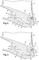
- the blades 16 are subjected to significant centrifugal forces and adopt a rectified angular position with respect to the axis of the rotor in which the downstream edges 42 of the blade roots abut on the rim 34 of the downstream wall.
- 32 of the throat ( figure 2 ) and the platforms 44 of the vanes are supported on the outer periphery of the upstream wall 32 of the groove and are spaced from the outer periphery of the downstream wall 32 of the groove, the radial clearances between the outer ends of the vanes 16 and the outer casing 14 are then minimized to improve the performance of the turbomachine.
- each blade has an annular rib 46 projecting towards the axis of the rotor which is hooked on the outer periphery of the upstream wall 32 of the groove, as shown in FIG. figure 2 .
- a one-piece annular seal 50 of elastomer and circular section is mounted in an annular groove 52 of the outer periphery of the downstream side wall 32 of the groove, this groove 52 opening radially outwardly under the downstream ends 48 of the platforms blades.
- the seal 50 has in the free state an outer diameter less than or equal to that of the groove 52 (as shown in dotted lines in FIG. figure 2 ) and is, when stopped, housed entirely in the groove.
- This seal 50 may be a seal and / or a vibration damping seal.
- the seal 50 expands radially outwards under the effect of centrifugal forces and is supported on internal downstream surfaces 48 of the blade platforms (as shown in solid lines), to prevent an air passage between the platforms of the blades and the outer periphery of the downstream wall 32 of the groove, and / or to exert pressure on the platforms and dampen the vibrations of the blades.
- the vanes 16 of the wheel swing slightly downstream and adopt another angular position with respect to the axis of the rotor, in which the downstream edges 42 of the blade roots come into contact with each other. support on the bottom 31 of the groove so that the radially outer ends of the blades 16 are likely to touch the outer casing 14, which may deteriorate the blades at startup and shutdown and thus reduce the performance of the turbomachine .
- the invention responds to this problem by means of an annular seal mounted in the groove 52 and which makes it possible, on stopping the turbomachine, to exert on the platforms 44 of the vanes an elastic force urging the blades 16 towards their position. operating in which the ends of the blades are spaced apart from the outer casing 14 and can not rub on it.
- the seal 54 has a substantially diamond-shaped section and comprises an outer peripheral lip 56 with a triangular section intended to protrude outside the groove 52 to bear against the internal downstream surfaces 48 of the platforms of the blades, and an inner peripheral lip 58 with a triangular section intended to rest on the bottom of the groove 52, when the seal 54 is mounted in the groove.
- the upstream and downstream edges 60 of the gasket 54 are intended to bear against the lateral walls of the groove 52.
- the dimensions and the hardness of the seal 54 have been determined so that on the one hand the vanes 16 of the wheel adopt substantially the same angular position when the turbine engine is stopped and in operation, and on the other hand, so that the seal 54 does not prevent the introduction of the blade roots 18 into the groove 20 of the disk and the circumferential displacement of the blades in this groove by friction of the surfaces 48 of the platforms on the seal 54.
- the seal 54 is elastically deformed between the platforms of the blades and the bottom of the groove 52 and exerts on these platforms a restoring force to ensure the correct positioning of the blades.
- the annular seal 54 has an outer diameter of approximately 1.20 meters, a Shore A hardness of between 50 and 100, for example approximately 75, and can withstand temperatures which can reach 150 ° C.
- This seal is for example made in "VITON A” or "VITON B”.
- the seal 62 has a section substantially X or H and comprises two outer peripheral lips 64 which protrude outside the groove 52 to bear on the inner surfaces downstream 48 platforms of the blades , and two inner peripheral lips 66 whose upstream and downstream lateral surfaces 68 are substantially flat and parallel and bear on the side walls of the groove 52, when the seal 62 is mounted in the groove 52.
- the seal 62 is elastically deformed between the platforms of the blades and the bottom of the groove 52 and exerts on the platforms a restoring force to ensure the correct positioning of the blades.
- the invention is not limited to the embodiments that have been described in the foregoing and represented in Figures 3 to 5 .
- the seal 54 or 62 which preferably has a shape symmetrical with respect to its median transverse plane, may have a shape in section different from those shown.
- the seal 54 or 62 could be mounted in an annular groove of the upstream side wall 32 of the groove, this groove opening under the upstream parts of the platforms 44 of the blades.
Landscapes
- Engineering & Computer Science (AREA)
- Mechanical Engineering (AREA)
- General Engineering & Computer Science (AREA)
- Structures Of Non-Positive Displacement Pumps (AREA)
- Turbine Rotor Nozzle Sealing (AREA)
Applications Claiming Priority (1)
| Application Number | Priority Date | Filing Date | Title |
|---|---|---|---|
| FR0601098A FR2897099B1 (fr) | 2006-02-08 | 2006-02-08 | Roue de rotor de turbomachine |
Publications (2)
| Publication Number | Publication Date |
|---|---|
| EP1818507A1 EP1818507A1 (fr) | 2007-08-15 |
| EP1818507B1 true EP1818507B1 (fr) | 2016-06-29 |
Family
ID=37075575
Family Applications (1)
| Application Number | Title | Priority Date | Filing Date |
|---|---|---|---|
| EP07290123.4A Active EP1818507B1 (fr) | 2006-02-08 | 2007-01-30 | Roue de rotor de turbomachine |
Country Status (5)
| Country | Link |
|---|---|
| US (1) | US8038403B2 (https=) |
| EP (1) | EP1818507B1 (https=) |
| JP (1) | JP4847887B2 (https=) |
| CA (1) | CA2577502C (https=) |
| FR (1) | FR2897099B1 (https=) |
Families Citing this family (4)
| Publication number | Priority date | Publication date | Assignee | Title |
|---|---|---|---|---|
| EP2157283A1 (de) * | 2008-08-18 | 2010-02-24 | Siemens Aktiengesellschaft | Schaufelbefestigung mit Dämpfungselement für eine Strömungsmaschine |
| FR2940350B1 (fr) | 2008-12-23 | 2011-03-18 | Snecma | Roue mobile de turbomachine a aubes en materiau composite munie d'un anneau ressort. |
| DE102009030397A1 (de) * | 2009-06-25 | 2010-12-30 | Mtu Aero Engines Gmbh | Befestigungsvorrichtung einer Turbinen- oder Verdichterschaufel |
| US9140136B2 (en) | 2012-05-31 | 2015-09-22 | United Technologies Corporation | Stress-relieved wire seal assembly for gas turbine engines |
Family Cites Families (15)
| Publication number | Priority date | Publication date | Assignee | Title |
|---|---|---|---|---|
| CH494341A (de) * | 1968-07-26 | 1970-07-31 | Sulzer Ag | Rotor für Turbomaschinen |
| GB2097480B (en) * | 1981-04-29 | 1984-06-06 | Rolls Royce | Rotor blade fixing in circumferential slot |
| JPS5857505A (ja) * | 1981-10-02 | 1983-04-05 | Hitachi Constr Mach Co Ltd | 電気油圧変換弁の制御装置 |
| JPS61132799A (ja) * | 1984-11-29 | 1986-06-20 | Toshiba Corp | 軸流圧縮機の羽根車 |
| US4767247A (en) * | 1987-02-24 | 1988-08-30 | Westinghouse Electric Corp. | Apparatus and method for preventing relative blade motion in steam turbine |
| US4878811A (en) * | 1988-11-14 | 1989-11-07 | United Technologies Corporation | Axial compressor blade assembly |
| GB2234299B (en) * | 1989-07-06 | 1994-01-05 | Rolls Royce Plc | Mounting system for engine components having dissimilar coefficients of thermal expansion |
| US5211536A (en) * | 1991-05-13 | 1993-05-18 | General Electric Company | Boltless turbine nozzle/stationary seal mounting |
| FR2700807B1 (fr) * | 1993-01-27 | 1995-03-03 | Snecma | Système de rétention et d'étanchéité d'aubes engagées dans des brochages axiaux d'un disque de rotor. |
| US6095750A (en) * | 1998-12-21 | 2000-08-01 | General Electric Company | Turbine nozzle assembly |
| EP1180196B1 (de) * | 1999-05-14 | 2005-02-16 | Siemens Aktiengesellschaft | Strömungsmaschine mit einem dichtsystem für einen rotor |
| US6375429B1 (en) * | 2001-02-05 | 2002-04-23 | General Electric Company | Turbomachine blade-to-rotor sealing arrangement |
| US6761538B2 (en) * | 2002-10-31 | 2004-07-13 | General Electric Company | Continual radial loading device for steam turbine reaction type buckets and related method |
| FR2856105B1 (fr) * | 2003-06-16 | 2007-05-25 | Snecma Moteurs | Amelioration de la capacite de retention d'une aube a attache marteau dissymetrique a l'aide des raidisseurs de plates-formes |
| US7334331B2 (en) * | 2003-12-18 | 2008-02-26 | General Electric Company | Methods and apparatus for machining components |
-
2006
- 2006-02-08 FR FR0601098A patent/FR2897099B1/fr not_active Expired - Lifetime
-
2007
- 2007-01-30 EP EP07290123.4A patent/EP1818507B1/fr active Active
- 2007-02-02 US US11/670,509 patent/US8038403B2/en active Active
- 2007-02-07 JP JP2007027909A patent/JP4847887B2/ja active Active
- 2007-02-08 CA CA2577502A patent/CA2577502C/fr active Active
Also Published As
| Publication number | Publication date |
|---|---|
| EP1818507A1 (fr) | 2007-08-15 |
| JP2007211777A (ja) | 2007-08-23 |
| JP4847887B2 (ja) | 2011-12-28 |
| CA2577502A1 (fr) | 2007-08-08 |
| FR2897099A1 (fr) | 2007-08-10 |
| US8038403B2 (en) | 2011-10-18 |
| US20070183894A1 (en) | 2007-08-09 |
| CA2577502C (fr) | 2014-08-19 |
| FR2897099B1 (fr) | 2012-08-17 |
Similar Documents
| Publication | Publication Date | Title |
|---|---|---|
| EP2060750B1 (fr) | Etage de turbine ou de compresseur, en particulier de turbomachine | |
| EP2780553B1 (fr) | Roue a aubes pour une turbomachine | |
| EP1811131B1 (fr) | Ensemble de redresseurs fixes sectorise pour un compresseur de turbomachine | |
| EP2582920B1 (fr) | Secteur angulaire de redresseur pour compresseur de turbomachine | |
| EP2366061B1 (fr) | Roue de turbine avec système de rétention axiale des aubes | |
| EP3679228A1 (fr) | Ensemble de turbine à secteurs d'anneau | |
| CA2647057C (fr) | Distributeur sectorise pour une turbomachine | |
| FR2980235A1 (fr) | Anneau pour une turbine de turbomachine | |
| FR2986836A1 (fr) | Tole annulaire anti-usure pour une turbomachine | |
| FR2972759A1 (fr) | Systeme d'etancheite et de retenue axiale des aubes pour une roue de turbine de turbomachine | |
| FR3099520A1 (fr) | Roue de turbomachine | |
| FR2971022A1 (fr) | Etage redresseur de compresseur pour une turbomachine | |
| FR3075869A1 (fr) | Roue mobile de turbine pour turbomachine d'aeronef, comprenant un anneau d'etancheite retenu radialement par des excroissances sur l'echasse des aubes | |
| EP1818507B1 (fr) | Roue de rotor de turbomachine | |
| FR2978793A1 (fr) | Rotor de turbine pour une turbomachine | |
| EP2060751A1 (fr) | Etage de turbine ou de compresseur d'un turboréacteur | |
| EP4544155B1 (fr) | Ensemble aubagé pour turbomachine, turbine pour turbomachine et turbomachine | |
| FR2965291A1 (fr) | Ensemble unitaire de disques de rotor pour une turbomachine | |
| WO2020021192A1 (fr) | Aube de turbine | |
| FR2710103A1 (fr) | Flasque de rotor de turbomachine et assemblage de ce flasque avec un rotor. | |
| FR3078740A1 (fr) | Joint d'etancheite dynamique a lechette comprenant une partie active en saillie circonferentiellement limitee | |
| FR3127524A1 (fr) | Partie statorique de turbomachine à anneau de maintien retenu tangentiellement | |
| FR3126447A1 (fr) | Roue mobile de turbomachine comprenant une pièce de butée axiale pour amortisseur |
Legal Events
| Date | Code | Title | Description |
|---|---|---|---|
| PUAI | Public reference made under article 153(3) epc to a published international application that has entered the european phase |
Free format text: ORIGINAL CODE: 0009012 |
|
| AK | Designated contracting states |
Kind code of ref document: A1 Designated state(s): AT BE BG CH CY CZ DE DK EE ES FI FR GB GR HU IE IS IT LI LT LU LV MC NL PL PT RO SE SI SK TR |
|
| AX | Request for extension of the european patent |
Extension state: AL BA HR MK YU |
|
| 17P | Request for examination filed |
Effective date: 20071103 |
|
| AKX | Designation fees paid |
Designated state(s): DE FR GB |
|
| GRAP | Despatch of communication of intention to grant a patent |
Free format text: ORIGINAL CODE: EPIDOSNIGR1 |
|
| INTG | Intention to grant announced |
Effective date: 20160204 |
|
| GRAS | Grant fee paid |
Free format text: ORIGINAL CODE: EPIDOSNIGR3 |
|
| GRAA | (expected) grant |
Free format text: ORIGINAL CODE: 0009210 |
|
| AK | Designated contracting states |
Kind code of ref document: B1 Designated state(s): DE FR GB |
|
| REG | Reference to a national code |
Ref country code: GB Ref legal event code: FG4D Free format text: NOT ENGLISH |
|
| REG | Reference to a national code |
Ref country code: DE Ref legal event code: R096 Ref document number: 602007046780 Country of ref document: DE |
|
| REG | Reference to a national code |
Ref country code: FR Ref legal event code: PLFP Year of fee payment: 11 |
|
| REG | Reference to a national code |
Ref country code: DE Ref legal event code: R097 Ref document number: 602007046780 Country of ref document: DE |
|
| PLBE | No opposition filed within time limit |
Free format text: ORIGINAL CODE: 0009261 |
|
| STAA | Information on the status of an ep patent application or granted ep patent |
Free format text: STATUS: NO OPPOSITION FILED WITHIN TIME LIMIT |
|
| 26N | No opposition filed |
Effective date: 20170330 |
|
| REG | Reference to a national code |
Ref country code: FR Ref legal event code: CD Owner name: SNECMA, FR Effective date: 20170713 |
|
| REG | Reference to a national code |
Ref country code: FR Ref legal event code: PLFP Year of fee payment: 12 |
|
| PGFP | Annual fee paid to national office [announced via postgrant information from national office to epo] |
Ref country code: GB Payment date: 20260122 Year of fee payment: 20 |
|
| PGFP | Annual fee paid to national office [announced via postgrant information from national office to epo] |
Ref country code: DE Payment date: 20260120 Year of fee payment: 20 |
|
| PGFP | Annual fee paid to national office [announced via postgrant information from national office to epo] |
Ref country code: FR Payment date: 20260128 Year of fee payment: 20 |