EP1818231B1 - Vehicle control system - Google Patents
Vehicle control system Download PDFInfo
- Publication number
- EP1818231B1 EP1818231B1 EP07002197A EP07002197A EP1818231B1 EP 1818231 B1 EP1818231 B1 EP 1818231B1 EP 07002197 A EP07002197 A EP 07002197A EP 07002197 A EP07002197 A EP 07002197A EP 1818231 B1 EP1818231 B1 EP 1818231B1
- Authority
- EP
- European Patent Office
- Prior art keywords
- vehicle
- target
- deceleration
- kdb
- evaluation index
- Prior art date
- Legal status (The legal status is an assumption and is not a legal conclusion. Google has not performed a legal analysis and makes no representation as to the accuracy of the status listed.)
- Active
Links
- 238000011156 evaluation Methods 0.000 claims description 179
- 230000001133 acceleration Effects 0.000 claims description 96
- 230000007423 decrease Effects 0.000 claims description 21
- 230000001276 controlling effect Effects 0.000 description 21
- 238000013459 approach Methods 0.000 description 14
- 238000012545 processing Methods 0.000 description 12
- 238000010586 diagram Methods 0.000 description 9
- 230000008859 change Effects 0.000 description 7
- 230000004048 modification Effects 0.000 description 6
- 238000012986 modification Methods 0.000 description 6
- 238000004364 calculation method Methods 0.000 description 4
- 238000013500 data storage Methods 0.000 description 4
- 238000001514 detection method Methods 0.000 description 4
- 239000012530 fluid Substances 0.000 description 4
- 238000000034 method Methods 0.000 description 4
- 230000009467 reduction Effects 0.000 description 4
- 210000001525 retina Anatomy 0.000 description 4
- 210000000695 crystalline len Anatomy 0.000 description 3
- 230000003247 decreasing effect Effects 0.000 description 3
- 230000000994 depressogenic effect Effects 0.000 description 3
- 239000004973 liquid crystal related substance Substances 0.000 description 2
- 230000004044 response Effects 0.000 description 2
- 230000003068 static effect Effects 0.000 description 2
- 230000000007 visual effect Effects 0.000 description 2
- 241000282326 Felis catus Species 0.000 description 1
- 230000005540 biological transmission Effects 0.000 description 1
- 238000002474 experimental method Methods 0.000 description 1
- 238000003825 pressing Methods 0.000 description 1
- 230000002265 prevention Effects 0.000 description 1
- 230000001105 regulatory effect Effects 0.000 description 1
- 238000005728 strengthening Methods 0.000 description 1
- 230000001131 transforming effect Effects 0.000 description 1
Images


Classifications
-
- B—PERFORMING OPERATIONS; TRANSPORTING
- B60—VEHICLES IN GENERAL
- B60T—VEHICLE BRAKE CONTROL SYSTEMS OR PARTS THEREOF; BRAKE CONTROL SYSTEMS OR PARTS THEREOF, IN GENERAL; ARRANGEMENT OF BRAKING ELEMENTS ON VEHICLES IN GENERAL; PORTABLE DEVICES FOR PREVENTING UNWANTED MOVEMENT OF VEHICLES; VEHICLE MODIFICATIONS TO FACILITATE COOLING OF BRAKES
- B60T8/00—Arrangements for adjusting wheel-braking force to meet varying vehicular or ground-surface conditions, e.g. limiting or varying distribution of braking force
- B60T8/17—Using electrical or electronic regulation means to control braking
- B60T8/1755—Brake regulation specially adapted to control the stability of the vehicle, e.g. taking into account yaw rate or transverse acceleration in a curve
-
- B—PERFORMING OPERATIONS; TRANSPORTING
- B60—VEHICLES IN GENERAL
- B60T—VEHICLE BRAKE CONTROL SYSTEMS OR PARTS THEREOF; BRAKE CONTROL SYSTEMS OR PARTS THEREOF, IN GENERAL; ARRANGEMENT OF BRAKING ELEMENTS ON VEHICLES IN GENERAL; PORTABLE DEVICES FOR PREVENTING UNWANTED MOVEMENT OF VEHICLES; VEHICLE MODIFICATIONS TO FACILITATE COOLING OF BRAKES
- B60T7/00—Brake-action initiating means
- B60T7/12—Brake-action initiating means for automatic initiation; for initiation not subject to will of driver or passenger
- B60T7/22—Brake-action initiating means for automatic initiation; for initiation not subject to will of driver or passenger initiated by contact of vehicle, e.g. bumper, with an external object, e.g. another vehicle, or by means of contactless obstacle detectors mounted on the vehicle
-
- B—PERFORMING OPERATIONS; TRANSPORTING
- B60—VEHICLES IN GENERAL
- B60W—CONJOINT CONTROL OF VEHICLE SUB-UNITS OF DIFFERENT TYPE OR DIFFERENT FUNCTION; CONTROL SYSTEMS SPECIALLY ADAPTED FOR HYBRID VEHICLES; ROAD VEHICLE DRIVE CONTROL SYSTEMS FOR PURPOSES NOT RELATED TO THE CONTROL OF A PARTICULAR SUB-UNIT
- B60W30/00—Purposes of road vehicle drive control systems not related to the control of a particular sub-unit, e.g. of systems using conjoint control of vehicle sub-units, or advanced driver assistance systems for ensuring comfort, stability and safety or drive control systems for propelling or retarding the vehicle
- B60W30/02—Control of vehicle driving stability
-
- B—PERFORMING OPERATIONS; TRANSPORTING
- B60—VEHICLES IN GENERAL
- B60W—CONJOINT CONTROL OF VEHICLE SUB-UNITS OF DIFFERENT TYPE OR DIFFERENT FUNCTION; CONTROL SYSTEMS SPECIALLY ADAPTED FOR HYBRID VEHICLES; ROAD VEHICLE DRIVE CONTROL SYSTEMS FOR PURPOSES NOT RELATED TO THE CONTROL OF A PARTICULAR SUB-UNIT
- B60W30/00—Purposes of road vehicle drive control systems not related to the control of a particular sub-unit, e.g. of systems using conjoint control of vehicle sub-units, or advanced driver assistance systems for ensuring comfort, stability and safety or drive control systems for propelling or retarding the vehicle
- B60W30/14—Adaptive cruise control
- B60W30/16—Control of distance between vehicles, e.g. keeping a distance to preceding vehicle
-
- B—PERFORMING OPERATIONS; TRANSPORTING
- B60—VEHICLES IN GENERAL
- B60W—CONJOINT CONTROL OF VEHICLE SUB-UNITS OF DIFFERENT TYPE OR DIFFERENT FUNCTION; CONTROL SYSTEMS SPECIALLY ADAPTED FOR HYBRID VEHICLES; ROAD VEHICLE DRIVE CONTROL SYSTEMS FOR PURPOSES NOT RELATED TO THE CONTROL OF A PARTICULAR SUB-UNIT
- B60W40/00—Estimation or calculation of non-directly measurable driving parameters for road vehicle drive control systems not related to the control of a particular sub unit, e.g. by using mathematical models
- B60W40/02—Estimation or calculation of non-directly measurable driving parameters for road vehicle drive control systems not related to the control of a particular sub unit, e.g. by using mathematical models related to ambient conditions
- B60W40/06—Road conditions
- B60W40/072—Curvature of the road
-
- B—PERFORMING OPERATIONS; TRANSPORTING
- B60—VEHICLES IN GENERAL
- B60W—CONJOINT CONTROL OF VEHICLE SUB-UNITS OF DIFFERENT TYPE OR DIFFERENT FUNCTION; CONTROL SYSTEMS SPECIALLY ADAPTED FOR HYBRID VEHICLES; ROAD VEHICLE DRIVE CONTROL SYSTEMS FOR PURPOSES NOT RELATED TO THE CONTROL OF A PARTICULAR SUB-UNIT
- B60W40/00—Estimation or calculation of non-directly measurable driving parameters for road vehicle drive control systems not related to the control of a particular sub unit, e.g. by using mathematical models
- B60W40/02—Estimation or calculation of non-directly measurable driving parameters for road vehicle drive control systems not related to the control of a particular sub unit, e.g. by using mathematical models related to ambient conditions
- B60W40/06—Road conditions
- B60W40/076—Slope angle of the road
-
- B—PERFORMING OPERATIONS; TRANSPORTING
- B60—VEHICLES IN GENERAL
- B60T—VEHICLE BRAKE CONTROL SYSTEMS OR PARTS THEREOF; BRAKE CONTROL SYSTEMS OR PARTS THEREOF, IN GENERAL; ARRANGEMENT OF BRAKING ELEMENTS ON VEHICLES IN GENERAL; PORTABLE DEVICES FOR PREVENTING UNWANTED MOVEMENT OF VEHICLES; VEHICLE MODIFICATIONS TO FACILITATE COOLING OF BRAKES
- B60T2201/00—Particular use of vehicle brake systems; Special systems using also the brakes; Special software modules within the brake system controller
- B60T2201/02—Active or adaptive cruise control system; Distance control
- B60T2201/022—Collision avoidance systems
-
- B—PERFORMING OPERATIONS; TRANSPORTING
- B60—VEHICLES IN GENERAL
- B60T—VEHICLE BRAKE CONTROL SYSTEMS OR PARTS THEREOF; BRAKE CONTROL SYSTEMS OR PARTS THEREOF, IN GENERAL; ARRANGEMENT OF BRAKING ELEMENTS ON VEHICLES IN GENERAL; PORTABLE DEVICES FOR PREVENTING UNWANTED MOVEMENT OF VEHICLES; VEHICLE MODIFICATIONS TO FACILITATE COOLING OF BRAKES
- B60T2201/00—Particular use of vehicle brake systems; Special systems using also the brakes; Special software modules within the brake system controller
- B60T2201/08—Lane monitoring; Lane Keeping Systems
- B60T2201/081—Lane monitoring; Lane Keeping Systems using distance control
-
- B—PERFORMING OPERATIONS; TRANSPORTING
- B60—VEHICLES IN GENERAL
- B60T—VEHICLE BRAKE CONTROL SYSTEMS OR PARTS THEREOF; BRAKE CONTROL SYSTEMS OR PARTS THEREOF, IN GENERAL; ARRANGEMENT OF BRAKING ELEMENTS ON VEHICLES IN GENERAL; PORTABLE DEVICES FOR PREVENTING UNWANTED MOVEMENT OF VEHICLES; VEHICLE MODIFICATIONS TO FACILITATE COOLING OF BRAKES
- B60T2201/00—Particular use of vehicle brake systems; Special systems using also the brakes; Special software modules within the brake system controller
- B60T2201/16—Curve braking control, e.g. turn control within ABS control algorithm
-
- B—PERFORMING OPERATIONS; TRANSPORTING
- B60—VEHICLES IN GENERAL
- B60T—VEHICLE BRAKE CONTROL SYSTEMS OR PARTS THEREOF; BRAKE CONTROL SYSTEMS OR PARTS THEREOF, IN GENERAL; ARRANGEMENT OF BRAKING ELEMENTS ON VEHICLES IN GENERAL; PORTABLE DEVICES FOR PREVENTING UNWANTED MOVEMENT OF VEHICLES; VEHICLE MODIFICATIONS TO FACILITATE COOLING OF BRAKES
- B60T2210/00—Detection or estimation of road or environment conditions; Detection or estimation of road shapes
- B60T2210/20—Road shapes
- B60T2210/24—Curve radius
-
- B—PERFORMING OPERATIONS; TRANSPORTING
- B60—VEHICLES IN GENERAL
- B60T—VEHICLE BRAKE CONTROL SYSTEMS OR PARTS THEREOF; BRAKE CONTROL SYSTEMS OR PARTS THEREOF, IN GENERAL; ARRANGEMENT OF BRAKING ELEMENTS ON VEHICLES IN GENERAL; PORTABLE DEVICES FOR PREVENTING UNWANTED MOVEMENT OF VEHICLES; VEHICLE MODIFICATIONS TO FACILITATE COOLING OF BRAKES
- B60T2210/00—Detection or estimation of road or environment conditions; Detection or estimation of road shapes
- B60T2210/30—Environment conditions or position therewithin
- B60T2210/32—Vehicle surroundings
-
- B60W2420/408—
-
- B—PERFORMING OPERATIONS; TRANSPORTING
- B60—VEHICLES IN GENERAL
- B60W—CONJOINT CONTROL OF VEHICLE SUB-UNITS OF DIFFERENT TYPE OR DIFFERENT FUNCTION; CONTROL SYSTEMS SPECIALLY ADAPTED FOR HYBRID VEHICLES; ROAD VEHICLE DRIVE CONTROL SYSTEMS FOR PURPOSES NOT RELATED TO THE CONTROL OF A PARTICULAR SUB-UNIT
- B60W2552/00—Input parameters relating to infrastructure
- B60W2552/20—Road profile
-
- B—PERFORMING OPERATIONS; TRANSPORTING
- B60—VEHICLES IN GENERAL
- B60W—CONJOINT CONTROL OF VEHICLE SUB-UNITS OF DIFFERENT TYPE OR DIFFERENT FUNCTION; CONTROL SYSTEMS SPECIALLY ADAPTED FOR HYBRID VEHICLES; ROAD VEHICLE DRIVE CONTROL SYSTEMS FOR PURPOSES NOT RELATED TO THE CONTROL OF A PARTICULAR SUB-UNIT
- B60W2552/00—Input parameters relating to infrastructure
- B60W2552/30—Road curve radius
-
- G—PHYSICS
- G08—SIGNALLING
- G08G—TRAFFIC CONTROL SYSTEMS
- G08G1/00—Traffic control systems for road vehicles
- G08G1/16—Anti-collision systems
- G08G1/166—Anti-collision systems for active traffic, e.g. moving vehicles, pedestrians, bikes
-
- G—PHYSICS
- G08—SIGNALLING
- G08G—TRAFFIC CONTROL SYSTEMS
- G08G1/00—Traffic control systems for road vehicles
- G08G1/16—Anti-collision systems
- G08G1/167—Driving aids for lane monitoring, lane changing, e.g. blind spot detection
Description
- The present invention relates to a vehicle control system.
- A vehicle control system, which determines a shape of a road that is ahead of a vehicle and controls a speed of the vehicle, is conventionally proposed (e.g.,
JP3432881 B2 JP3432881 B2 - However, when the vehicle speed V0 is larger than the possible traveling vehicle speed, the vehicle speed control means in the above vehicle control system does not set a target vehicle speed to automatically decelerate the vehicle such that the vehicle travels with the target vehicle speed. Therefore, there is a possibility that the vehicle is unduly decelerated by the automatic deceleration.
- Furthermore, the above vehicle speed control means does not automatically accelerate the vehicle when the vehicle speed V0 is smaller than the possible traveling vehicle speed. Hence, the vehicle speed control means cannot assist a driver of the vehicle with his/her drive operation of the vehicle in a comprehensive manner when the vehicle travels along the curve.
-
EP-A-0 941 902 relates to a vehicle dynamic control system which carries out warning and deceleration control in order to savely pass through a curve on a travelling road in front of a vehicle. The vehicle control system seems to comprise a distance obtaining means, a curvature radius obtaining means, a target vehicle speed setting means, a vehicle speed obtaining means, a target vehicle deceleration calculation means and a vehicle control means to carry out the above-mentioned warning and deceleration control. -
US 6 393 361 B1 relates to a dangerous approach prevention device for a vehicle and states that a braking force of the vehicle is adjusted based on an "approach index" indicating a level of dangerous approach to the preceding vehicle, and that said "approach index" is a time for colliding with said preceding vehicle. - The present invention addresses the above disadvantages. Thus, it is an objective of the present invention to provide a vehicle control system, which decelerates a vehicle such that the vehicle travels along a curve of a road with a vehicle speed, with which the vehicle can travel safely. It is another objective of the present invention to provide a vehicle control system, which assists a driver of the vehicle with his/her drive operation of the vehicle in a comprehensive manner when the vehicle travels along the curve.
- To achieve the objective of the present invention, there is provided a vehicle control system for controlling a vehicle as claimed in claims 1 and 2. The vehicle control system includes a distance obtaining means, an evaluation index calculating means, a curvature radius obtaining means, a target vehicle speed setting means, a vehicle speed obtaining means, a target vehicle deceleration calculating means, and a vehicle control means. The distance obtaining means is for obtaining a distance between the vehicle and a road associated object on a road. The road associated object is an object located along an extension line of a traveling direction of the vehicle, and at a boundary of a curve of the road or in a vicinity of the boundary, wherein the curve exists ahead of the vehicle. The evaluation index calculating means is for calculating an approaching/separating state evaluation index that indicates a positional relationship between the vehicle and the road associated object. The approaching/separating state evaluation index increases when a relative speed between the vehicle and the road associated object increases at a time of approaching of the vehicle to the road associated object. The approaching/separating state evaluation index for the relative speed increases at a faster rate as the distance decreases. The curvature radius obtaining means is for obtaining a curvature radius of the curve. The target vehicle speed setting means is for setting a target vehicle speed of the vehicle, with which the vehicle travels along the curve, based on the curvature radius of the curve. The vehicle speed obtaining means is for obtaining a current speed of the vehicle. The target vehicle deceleration calculating means is for calculating a target vehicle deceleration, with which the vehicle is controlled to travel so that the vehicle travels along the curve with the target vehicle speed, based on the approaching/separating state evaluation index, the distance, the current speed of the vehicle, and the target vehicle speed. The vehicle control means is for controlling the vehicle to decelerate such that a deceleration of the vehicle coincides with the target vehicle deceleration, when the speed of the vehicle is larger than the target vehicle speed.
- To achieve the objective of the present invention, there is also provided a vehicle control system for controlling a vehicle. The vehicle control system includes a distance obtaining means, an evaluation index calculating means, a curvature radius obtaining means, a target vehicle speed setting means, a vehicle speed obtaining means, a target vehicle acceleration/deceleration calculating means, and a vehicle control means. The distance obtaining means is for obtaining a distance between the vehicle and a road associated object on a road. The road associated object is an object located along an extension line of a traveling direction of the vehicle, and at a boundary of a curve of the road or in a vicinity of the boundary, wherein the curve exists ahead of the vehicle. The evaluation index calculating means is for calculating an approaching/separating state evaluation index that indicates a positional relationship between the vehicle and the road associated object. The approaching/separating state evaluation index increases when a relative speed between the vehicle and the road associated object increases at a time of approaching of the vehicle to the road associated object. The approaching/separating state evaluation index for the relative speed increases at a faster rate as the distance decreases. The curvature radius obtaining means is for obtaining a curvature radius of the curve. The target vehicle speed setting means is for setting a target vehicle speed of the vehicle, with which the vehicle travels along the curve, based on the curvature radius of the curve. The vehicle speed obtaining means is for obtaining a current speed of the vehicle. The target vehicle acceleration/deceleration calculating means is for calculating a target vehicle acceleration or deceleration, with which the vehicle is controlled to travel so that the vehicle travels along the curve with the target vehicle speed, based on the approaching/separating state evaluation index, the distance, the current speed of the vehicle, and the target vehicle speed. The vehicle control means is for controlling the vehicle such that an acceleration or deceleration of the vehicle coincides with the target vehicle acceleration or deceleration, respectively, based on a comparison between the current speed of the vehicle and the target vehicle speed.
- As well, to achieve the objective of the present invention, there is provided a vehicle control system for controlling a vehicle. The vehicle control system includes a distance obtaining means, a relative speed obtaining means, an evaluation index calculating means, a turning radius calculating means, a target lateral acceleration setting means, a target relative speed calculating means, a target relative deceleration calculating means, and a vehicle control means. The distance obtaining means is for obtaining a distance between the vehicle and an obstruction on a road. The obstruction exists on the road, which is ahead of the vehicle in a traveling direction of the vehicle. The relative speed obtaining means is for obtaining a relative speed between the vehicle and the obstruction. The evaluation index calculating means is for calculating an approaching/separating state evaluation index that indicates a positional relationship between the vehicle and the obstruction. The approaching/separating state evaluation index increases when the relative speed increases at a time of approaching of the vehicle to the obstruction. The approaching/separating state evaluation index for the relative speed increases at a faster rate as the distance decreases. The turning radius calculating means is for calculating a turning radius of the vehicle, which is necessary for the vehicle to avoid a collision with the obstruction, based on the distance. The target lateral acceleration setting means is for setting a target value of a lateral acceleration, which is generated in the vehicle in a lateral direction of the vehicle through a steering operation by a driver of the vehicle to avoid the collision. The target relative speed calculating means is for calculating a target relative speed between the vehicle and the obstruction based on the turning radius and the target value of the lateral acceleration. The target relative deceleration calculating means is for calculating a target relative deceleration between the vehicle and the obstruction based on the distance, the relative speed, and the approaching/separating state evaluation index. The vehicle control means is for controlling the vehicle to decelerate such that a relative deceleration between the vehicle and the obstruction coincides with the target relative deceleration when the relative speed is larger than the target relative speed. The vehicle is controlled to travel with the target relative deceleration by the vehicle control means so that the vehicle is decelerated to the target relative speed.
- Moreover, to achieve the objective of the present invention, there is also provided a vehicle control system for controlling a vehicle. The vehicle control system includes a distance obtaining means, an evaluation index calculating means, a curvature radius obtaining means, a target vehicle speed setting means, a vehicle speed obtaining means, a relative speed obtaining means, a turning radius calculating means, a target lateral acceleration setting means, a target relative speed calculating means, a target vehicle acceleration/deceleration calculating means, a target relative deceleration calculating means, and a vehicle control means. The distance obtaining means is for obtaining a distance between the vehicle and one of an obstruction and a road associated object. The vehicle travels along a road, and the obstruction exists on a curve of the road, wherein the curve exists ahead of the vehicle in a traveling direction of the vehicle. The road associated object is an object located at a boundary of the curve or in a vicinity of the boundary. The evaluation index calculating means is for calculating an approaching/separating state evaluation index that indicates a positional relationship between the vehicle and the one of the obstruction and the road associated object. The approaching/separating state evaluation index increases when a relative speed between the vehicle and the one of the obstruction and the road associated object increases at a time of approaching of the vehicle to the one of the obstruction and the road associated object. The approaching/separating state evaluation index for the relative speed increases at a faster rate as the distance decreases. The curvature radius obtaining means is for obtaining a curvature radius of the curve. The target vehicle speed setting means is for setting a target vehicle speed of the vehicle, with which the vehicle travels along the curve, based on the curvature radius of the curve. The vehicle speed obtaining means is for obtaining a current speed of the vehicle. The relative speed obtaining means is for obtaining the relative speed between the vehicle and the obstruction. The turning radius calculating means is for calculating a turning radius of the vehicle, which is necessary for the vehicle to avoid a collision with the obstruction, based on the distance between the vehicle and the obstruction. The target lateral acceleration setting means is for setting a target value of a lateral acceleration, which is generated in the vehicle in a lateral direction of the vehicle through a steering operation by a driver of the vehicle to avoid the collision. The target relative speed calculating means is for calculating a target relative speed between the vehicle and the obstruction based on the turning radius and the target value of the lateral acceleration. The target vehicle acceleration/deceleration calculating means is for calculating a target vehicle acceleration or deceleration, with which the vehicle is controlled to travel so that the vehicle travels along the curve with the target vehicle speed, based on the approaching/separating state evaluation index between the vehicle and the road associated object, the distance between the vehicle and the road associated object, the current speed of the vehicle, and the target vehicle speed. The target relative deceleration calculating means is for calculating a target relative deceleration between the vehicle and the obstruction based on the distance between the vehicle and the obstruction, the relative speed, and the approaching/separating state evaluation index between the vehicle and the obstruction. The vehicle control means is for controlling the vehicle to decelerate such that a relative deceleration between the vehicle and the obstruction coincides with the target relative deceleration when the obstruction exists on the curve and the relative speed is larger than the target relative speed, wherein the vehicle is controlled to travel with the target relative deceleration by the vehicle control means so that the vehicle is decelerated to the target relative speed. As well, the vehicle control means is for controlling the vehicle such that an acceleration or deceleration of the vehicle coincides with the target vehicle acceleration or deceleration, respectively, based on a comparison between the current speed of the vehicle and the target vehicle speed when the obstruction does not exist on the curve.
- Furthermore, to achieve the objective of the present invention, there is also provided a vehicle control system for controlling a vehicle. The vehicle control system includes a distance obtaining means, a relative speed detecting means, an evaluation index calculating means, a deceleration target calculating means, a deceleration target determining means, a target value setting means, a target vehicle deceleration calculating means, and a braking force control means. The distance obtaining means is for obtaining a distance between the vehicle and a road associated object on a road. The road associated object is an object located along an extension line of a traveling direction of the vehicle, and at a boundary of a curve of the road or in a vicinity of the boundary, wherein the curve exists ahead of the vehicle. The relative speed detecting means is for detecting a relative speed between the vehicle and the road associated object. The evaluation index calculating means is for calculating an approaching/separating state evaluation index that indicates a positional relationship between the vehicle and the road associated object. The approaching/separating state evaluation index increases when the relative speed increases, at a time of approaching of the vehicle to the road associated object. The approaching/separating state evaluation index for the relative speed increases at a faster rate as the distance decreases. The deceleration target calculating means is for calculating a deceleration target based on a normal deceleration of the vehicle, the distance, and the relative speed. The deceleration target indicates an index of a timing, with which braking force applied through a brake system of the vehicle when the vehicle proceeds into the curve or travels along the curve is controlled. The deceleration target determining means is for determining whether the approaching/separating state evaluation index is larger than the deceleration target. The target value setting means is for setting a target value of the approaching/separating state evaluation index, such that the target value of the approaching/separating state evaluation index increases linearly from an initial value at a constant slope when the distance decreases. The initial value is the approaching/separating state evaluation index at a time when the deceleration target determining means determines that the approaching/separating state evaluation index is larger than the deceleration target. The constant slope is a slope of the approaching/separating state evaluation index at the time when the deceleration target determining means determines that the approaching/separating state evaluation index is larger than the deceleration target. The target vehicle deceleration calculating means is for calculating a target vehicle deceleration based on a target relative speed between the vehicle and the road associated object, and a present relative speed between the vehicle and the road associated object, wherein the target relative speed is obtained based on the target value of the approaching/separating state evaluation index. The braking force control means is for controlling the braking force applied through the brake system such that a deceleration of the vehicle coincides with the target vehicle deceleration when the vehicle proceeds into the curve or travels along the curve.
- Lastly, to achieve the objective of the present invention, there is provided a vehicle control system for controlling a vehicle. The vehicle control system includes a distance obtaining means, a relative speed detecting means, an evaluation index calculating means, a target value setting means, a target vehicle deceleration calculating means, and a braking force control means. The distance obtaining means is for obtaining a distance between the vehicle and a road associated object on a road. The road associated object is an object located along an extension line of a traveling direction of the vehicle, and at a boundary of a curve of the road or in a vicinity of the boundary, wherein the curve exists ahead of the vehicle. The relative speed detecting means is for detecting a relative speed between the vehicle and the road associated object. The evaluation index calculating means is for calculating an approaching/separating state evaluation index that indicates a positional relationship between the vehicle and the road associated object. The approaching/separating state evaluation index increases when the relative speed increases at a time of approaching of the vehicle to the road associated object. The approaching/separating state evaluation index for the relative speed increases at a faster rate as the distance decreases. The target value setting means is for setting a target value of the approaching/separating state evaluation index, such that the target value of the approaching/separating state evaluation index increases linearly from an initial value at a constant slope when the distance decreases. The initial value is the approaching/separating state evaluation index at a time when a driver of the vehicle starts a drive operation to decelerate the vehicle when the vehicle proceeds into the curve or travels along the curve. The constant slope is a slope of the approaching/separating state evaluation index at the time when the driver starts the drive operation to decelerate the vehicle. The target vehicle deceleration calculating means is for calculating a target vehicle deceleration based on a target relative speed between the vehicle and the road associated object and a present relative speed between the vehicle and the road associated object, wherein the target relative speed is obtained based on the target value of the approaching/separating state evaluation index. The braking force control means is for controlling braking force, which is applied through a brake system of the vehicle, such that a deceleration of the vehicle coincides with the target vehicle deceleration, when the vehicle proceeds into the curve or travels along the curve.
- The invention, together with additional objectives, features and advantages thereof, will be best understood from the following description, the appended claims and the accompanying drawings in which:
-
FIG. 1 is a block diagram showing an overall configuration of a vehicle drive assist system according to a first embodiment of the present invention; -
FIG. 2 is an illustrative view illustrating a present approaching/separating state evaluation index between a vehicle and a road associated object; -
FIG. 3 is a functional block diagram of a vehicle control unit according to the first embodiment; -
FIG. 4 is an illustrative view illustrating a curvature radius of a curve of a road, a distance between the road associated object and a front end of the vehicle, a distance between the front end of the vehicle and a central axis of a front wheel of the vehicle, and a distance between a central point of width of the vehicle and the road associated object on the central axis of the front wheel according to the first embodiment; -
FIG. 5A is a schematic view showing examples of a lane marking, a reflective plate, a guardrail, and a curbstone according to the first embodiment; -
FIG. 5B is a schematic view showing examples of a pole and a delineator according to the first embodiment; -
FIG. 6 is a flowchart showing control processing performed in a curve travel ECU according to the first embodiment; -
FIG. 7 is a block diagram showing an overall configuration of a vehicle drive assist system according to a second embodiment of the present invention; -
FIG. 8 is an illustrative view illustrating the present approaching/separating state evaluation index between the vehicle and an obstruction such as a preceding vehicle; -
FIG. 9 is a functional block diagram of a vehicle control unit according to the second embodiment; -
FIG. 10A is an illustrative view illustrating a future locus of a projection plane of the vehicle; -
FIG. 10B is an illustrative view illustrating the projection plane of the vehicle; -
FIG. 11 is an illustrative view illustrating a turning radius that is necessary for the vehicle to avoid a collision with the preceding vehicle; -
FIG. 12 is a flowchart showing control processing performed in a curve travel ECU according to the second embodiment; -
FIG. 13 is a block diagram showing an overall configuration of a vehicle brake control system according to a third embodiment of the present invention; -
FIG. 14 is a diagram showing a variation characteristic of an approaching/separating state evaluation index; -
FIG. 15 is a flowchart showing assistive control of braking force; -
FIG. 16 is an illustrative diagram illustrating a method of calculating a target approaching/separating state evaluation index; and -
FIG. 17 is a flowchart showing control of the braking force according to a fourth embodiment of the present invention. - Embodiments of the present invention will be described below with reference to the accompanying drawings. The embodiments will be described with respect to an application of a vehicle control system of the present invention to a vehicle drive assist system.
-
FIG. 1 shows an overall configuration of a vehicle drive assist system according to a first embodiment. As shown inFIG. 1 , the vehicle drive assist system includes a VSC_ECU 10, arudder angle sensor 20, aG sensor 30, ayaw rate sensor 40, anENG_ECU 50, aCCD camera 60a, animage recognition processor 60b, aradar 70, anoperation switch 80, anavigation system 90, and acurve travel ECU 100. - The
VSC_ECU 10 controls a brake actuator (not shown) that applies braking force to a vehicle, and has a function of controlling a Vehicle Stability Control (VSC; a registered trademark) that controls skidding of the vehicle. TheVSC_ECU 10 receives information about target braking force from an in-vehicle LAN, and controls the brake actuator to generate the target braking force. Moreover, theVSC_ECU 10 transmits information about a speed (a vehicle speed) Vs0 of the vehicle and a brake pressure to the in-vehicle LAN. Therudder angle sensor 20 detects information about a steering angle of the vehicle, and transmits the detected information to the in-vehicle LAN. - The
G sensor 30 is an acceleration sensor that detects an acceleration (back-and-forth acceleration) that is generated in a back-and-forth direction of the vehicle, and transmits information about the detected back-and-forth acceleration to the in-vehicle LAN. Theyaw rate sensor 40 detects an angular speed (a yaw rate) around a vertical axis of the vehicle, and transmits information about the detected yaw rate to the in-vehicle LAN. - The
ENG_ECU 50 receives information about target driving force from the in-vehicle LAN, and controls a throttle actuator (not shown) to generate the target driving force. TheCCD camera 60a is an image taking means for taking an image, which captures a predetermined range ahead of the vehicle, and outputs the image to therecognition processor 60b. Therecognition processor 60b performs predetermined image recognition processing on the inputted image to recognize road associated objects, such as a lane marking M1, a pole M2, a guardrail M3, and a curbstone M4, for example. The road associated objects may be located at a boundary of a curve of the road ahead of the vehicle, or in its vicinity (FIGS. 5A, 5B ). Then, therecognition processor 60b obtains a relative position of the vehicle to the road associated object, and outputs information about a type of the road associated object and the relative position to thecurve travel ECU 100. - The
radar 70, for example, applies a laser light to a predetermined range ahead of the vehicle and receives a reflected light to detect distances to the road associated objects such as a reflective plate M5 and a delineator M6, deviation amounts (lateral deviation amounts) of central axes of the road associated objects from a widthwise central axis of the vehicle, and the like. The reflective plate M5 indicates reflected light intensity that is equal to or higher than predetermined intensity, and the road associated objects may be located at the boundary of the curve of the road or in its vicinity as shown inFIGS. 5A, 5B . Then, theradar 70 outputs information about the distances to the road associated objects, the lateral deviation amounts and the like to thecurve travel ECU 100. - The
operation switch 80 is a group of switches that a driver of the vehicle operates. Operational information that is inputted through the group of switches is outputted to thecurve travel ECU 100. Thenavigation system 90 includes a geomagnetic sensor, a gyroscope, a distance sensor, a position detector, a road map data storage, a color display, and a control circuit, which are all known. The position detector includes a GPS (global positioning system) receiver for a GPS that detects a position of the vehicle based on radio waves from GPS satellites, and the like. The road map data storage stores road map data. Liquid crystal or a CRT, for example, is employed in the color display. - The road map data includes link data and node data for expressing roads on a map using links and nodes, respectively. The link data and node data include information about coordinates of starting points and endpoints of the links, link length, passing division width, and curvature radiuses of the roads. The
navigation system 90 identifies a present position of the vehicle in response to a command from thecurve travel ECU 100, and outputs the link data and node data on the curve, which exists within the predetermined range ahead of the vehicle. - The
curve travel ECU 100 includes an approaching/separating state evaluationindex calculating unit 110 and avehicle control unit 120. Thecurve travel ECU 100 functions mainly as a microcomputer, and includes a known CPU, ROM, RAM, and I/O, and a bus that connects them. - When the curve exists ahead of the vehicle in its traveling direction, the
curve travel ECU 100 sets a target vehicle speed, with which the vehicle travels along the curve. Then, thecurve travel ECU 100 calculates a target vehicle acceleration/deceleration, which is used for accelerating/decelerating the vehicle to the target vehicle speed. Based on a comparison between the target vehicle speed and a vehicle speed of the vehicle, thecurve travel ECU 100 controls the vehicle to accelerate/decelerate so that the acceleration /deceleration of the vehicle reaches the target vehicle acceleration/deceleration. - Using the following equation (1), the evaluation
index calculating unit 110 calculates a present approaching/separating state evaluation index KdB_p between the vehicle and the road associated object, from a distance D between the vehicle and the road associated object located on the curve that exists ahead of the vehicle (i.e., a distance between the vehicle and a point at which the vehicle deviates from the curve), and the vehicle speed Vs0 using the following equation (1). In addition, |-2 × Vs0| in the equation (1) expresses an absolute value of (-2 × Vs0).
- As above, the road associated objects such as the lane marking M1, pole M2, guardrail M3, curbstone M4, reflective plate M5, and delineator M6 are located at the boundary of the curve, or in its vicinity. Thus, the distance D is obtained from positions of these road associated objects. Alternatively, the distance D may be obtained using the link data and node data in the road map data, and a detected result in the GPS receiver.
- An explanation as to the above equation (1) will be given below. When a static object (e.g., a stopped vehicle) exists ahead of the vehicle as shown in
FIG. 2 , an area (S) of an image of the stopped vehicle is expressed in the following equation (2), given actual height (H0) and width (W0) of the stopped vehicle, an area (So (=W0 × H0)), height (H) and width (W) of the image of the stopped vehicle, which is projected on (a retina of) an eye of the driver of the vehicle, the area (S (=W × H)), a distance (D, which equals a distance Do between the stopped vehicle and the vehicle for convenience sake) between the stopped vehicle and (a crystalline lens of) the eye of the driver, and a focal length (f) of the eye of the driver.
- A degree of variation in the area S of the image of the stopped vehicle per unit time dS/dt (i.e., area change of the image of the stopped vehicle) is expressed in the following equation (3). Additionally, a symbol "∝" in the equation (3) expresses a proportional relationship.

- The following equation (4) is derived by partially differentiating the above equation (3) with respect to the distance D.

- The area change dS/dt of the image of the stopped vehicle can be used as an evaluation index of an approaching/separating state between the vehicle and the stopped vehicle. Hence, the present evaluation index KdB_p between the vehicle and the road associated object as the static object is obtained as expressed in the above equation (1) by making the following calculation. That is, by expressing a result of multiplying the above equation (4) by a constant number in logarithm (decibel [dB]) and then further multiplying the result expressed in logarithm by a constant number, the present evaluation index KdB_p is obtained.
- Alternatively, since the present evaluation index KdB_p is obtained from the degree of variation in the area S of an image of the road associated object per unit time dS/dt, the present evaluation index KdB_p may be obtained from a degree of variation in a size of the road associated object in an image taken by the
CCD camera 60a per unit time. -
FIG. 3 shows a functional block diagram of thevehicle control unit 120. An approaching/separating state evaluationindex obtaining unit 201 obtains the present evaluation index KdB_p, which is calculated in the evaluationindex calculating unit 110. - A road surface µ obtaining
unit 202 determines a road surface friction coefficient µ from a road surface state of the road, along which the vehicle is traveling. The road surface state is detected by a road surface state detector (not shown). Alternatively, the road surface friction coefficient µ may be determined, for example, in the following manner. That is, the road surface states such as dryness, moistness, snow covering, and a freeze are related to the road surface friction coefficient µ beforehand, and the driver selects certain road surface states from the dryness, moistness, snow covering, freeze and the like. Then, the road surface friction coefficient µis determined from the road surface states selected by the driver. - In view of the road surface friction coefficient µ, a target lateral
acceleration setting unit 203 sets a target lateral acceleration Gy, at which the vehicle aims to travel along the curve. The target lateral acceleration Gy indicates a maximum value of a lateral acceleration, at which the vehicle can travel along the curve safely. - A road curvature
radius obtaining unit 204 obtains a curvature radius R of the curve ahead of the vehicle. With reference toFIG. 4 , an explanation as to the curvature radius R of the curve will be given below. In addition, in a common road, easement curve zones are formed before and after a circular curve zone as in, a straight road zone → the easement curve (e.g., clothoid, cubical parabola) zone → the circular curve zone -> the easement curve zone→ the straight road zone. However, in the first embodiment, for the purpose of simplifying the explanation, the curvature radius R of the curve, which consists of the circular curve zone alone as shown inFIG. 4 , will be described. - When the curve exists ahead of the vehicle, the curvature
radius obtaining unit 204 obtains a distance between a center (O) of a circular curve of the curve and a center line of a passing division of the vehicle as the curvature radius R of the curve. - Alternatively, the road curvature
radius obtaining unit 204 may obtain the curvature radius R based on the link data and node data in the road map data, which are outputted from thenavigation system 90. As well, the road curvatureradius obtaining unit 204 may estimate the curvature radius R of the curve from information about the road associated objects such as the lane marking M1, pole M2, guardrail M3, curbstone M4, reflective plate M5, and delineator M6. The information about the road associated objects is outputted from theradar 70 and therecognition processor 60b. In such a case, when the curvature radius R is estimated from the information about the pole M2, guardrail M3, curbstone M4, reflective plate M5, and delineator M6, an approximated curve may be obtained from the information, thereby obtaining the curvature radius R of the approximated curve. - In addition, as shown in
FIG. 4 , given the distance D between the vehicle and the road associated object (e.g., the lane marking M1, pole M2, guardrail M3, curbstone M4, reflective plate M5, and delineator M6) located in an extension line of the traveling direction of the vehicle, a distance (Y) between a front end of the vehicle and a central axis of a front wheel of the vehicle, and a distance (L) between a central point of width of the vehicle and the road associated object on the central axis of the front wheel, the following equation (5) is obtained.
- Thus, the curvature radius R of the curve may be obtained by calculating the following equation (6), which is obtained from the above equation (5).

- A target vehicle
speed setting unit 205 sets a target vehicle speed Vs0_t, with which the vehicle travels along the curve ahead of the vehicle by calculating the following equation (7) using the target lateral acceleration Gy and the curvature radius R of the curve.
- A target vehicle acceleration/
deceleration calculating unit 206 compares the present vehicle speed Vs0 with the target vehicle speed Vs0_t. If a difference between the present vehicle speed Vs0 and the target vehicle speed Vs0_t is smaller than a predetermined difference, the acceleration/deceleration calculating unit 206 calculates the target vehicle acceleration/deceleration to maintain the present vehicle speed Vs0. - On the other hand, if the above difference is larger than the predetermined difference, the acceleration/
deceleration calculating unit 206 obtains a target vehicle acceleration/deceleration dVs0/dt to accelerate or decelerate the vehicle to the target vehicle speed Vs0_t by calculating the following equation (8) using the present evaluation index KdB_p, the distance D between the vehicle and the road associated object located in the extension line of the traveling direction of the vehicle, the vehicle speed Vs0, and the target vehicle speed Vs0_t.
- The above equation (8), which is obtained from the above equation (1), expresses a target value of a vehicle acceleration/deceleration, which is used for accelerating/decelerating the vehicle to the target vehicle speed Vs0_t with the present evaluation index KdB_p maintained. The equation (8) is obtained in the following manner. First, the equation (1) is transformed into the following equations (9), (10).


- By differentiating the equation (10) with respect to time, the following equation (11) is obtained.

- The above equation (11) expresses the target value of the vehicle acceleration/deceleration to maintain the present evaluation index KdB_p. By taking the target vehicle speed Vs0_t into consideration in the equation (11), the target vehicle acceleration/deceleration dVs0/dt is expressed in the following equation (12).

- Lastly, the acceleration/
deceleration calculating unit 206 calculates a final value of the target vehicle acceleration/deceleration dVs0/dt in the above equation (8) by multiplying the equation (12) by gain, which is a positive value and is equal to or smaller than one. Additionally, the range of the gain will be examined below. When the vehicle, which is approaching the road associated object with the vehicle speed Vs0, starts to decelerate with a constant vehicle deceleration GG, for example, a travel distance DD, which is traveled by the vehicle until the vehicle stops at a position where the vehicle contacts the road associated object, is expressed in the following equation (13).
- Following this, a ratio is obtained by the following equation (14) between the vehicle deceleration GG, with which the vehicle travels until the vehicle stops at the position where the vehicle contacts the road associated object, and the target vehicle acceleration/deceleration dVs0/dt (gain=1.000) to maintain the present evaluation index KdB_p.

- By substituting the equation (10) for the vehicle speed Vs0 in the above equation (14), the following equation (15) is obtained.

- Therefore, by setting the gain at 0.167, the target vehicle acceleration/deceleration dVs0/dt, with which the vehicle travels in order that the vehicle stops at the position where the vehicle contacts the road associated object, can be calculated. Consequently, the gain covers a range of 0.167 to 1.000.
- When the difference between the present vehicle speed Vs0 and the target vehicle speed Vs0_t is larger than the predetermined difference, and the vehicle speed Vs0 is larger than the target vehicle speed Vs0_t, the target vehicle acceleration/deceleration dVs0/dt calculated by the above equation (8) expresses the deceleration (with a plus sign) with which the vehicle aims to travel. Accordingly, by controlling the vehicle to decelerate such that it travels with the target vehicle acceleration/deceleration dVs0/dt, the vehicle speed Vs0 can be decreased to the target vehicle speed Vs0_t with the present evaluation index KdB_p maintained.
- On the other hand, when the vehicle speed Vs0 is smaller than the target vehicle speed Vs0_t, the target vehicle acceleration/deceleration dVs0/dt calculated by the above equation (8) expresses the acceleration (with a minus sign) with which the vehicle aims to travel. Accordingly, by controlling the vehicle to accelerate such that it travels with the target vehicle acceleration/deceleration dVs0/dt, the vehicle speed Vs0 can be increased to the target vehicle speed Vs0_t with the present evaluation index KdB_p maintained.
- In addition, the acceleration/
deceleration calculating unit 206 may correct the target vehicle acceleration/deceleration dVs0/dt according to the road surface friction coefficient µ on the curve ahead of the vehicle. This is because the target braking force cannot sometimes be obtained due to the road surface friction coefficient µ. - A target driving/braking
force calculating unit 207 calculates target driving/braking force to be applied to the vehicle, such that the acceleration or deceleration of the vehicle reaches the target vehicle acceleration/deceleration dVs0/dt calculated by the acceleration/deceleration calculating unit 206, and transmits information about the target driving/braking force to the in-vehicle LAN. - Next, control processing performed in the
curve travel ECU 100 will be described with reference to a flowchart inFIG. 6 . To begin with, vehicle state quantity (e.g., the vehicle speed Vs0) is obtained at step 10 (S10). At step 20 (S20), the distance D between the vehicle and the road associated object located in the extension line of the traveling direction of the vehicle is obtained, and the present evaluation index KdB_p of the vehicle is calculated with respect to the road associated object using the distance D. At step 30 (S30), the target vehicle speed Vs0_t, with which the vehicle travels along the curve ahead of the vehicle, is calculated (is set). - At step 40 (S40), the present vehicle speed Vs0 is compared with the target vehicle speed Vs0_t that is set at S30, and it is determined whether the difference between the present vehicle speed Vs0 and the target vehicle speed Vs0_t is smaller than the predetermined difference. If it is determined that the difference is smaller than the predetermined difference (YES), control proceeds to step 60 (S60), whereas control proceeds to step 50 (S50) if it determined that the difference is not smaller than the predetermined difference (NO).
- At S50, if the present vehicle speed Vs0 is larger than the target vehicle speed Vs0_t, the target vehicle deceleration dVs0/dt that is used for decelerating the vehicle to the target vehicle speed Vs0_t is calculated. If the present vehicle speed Vs0 is smaller than the target vehicle speed Vs0_t the target vehicle acceleration dVs0/dt that is used for accelerating the vehicle to the target vehicle speed Vs0_t is calculated.
- The target vehicle acceleration/deceleration to maintain the present vehicle speed Vs0 is calculated at S60. At step 70 (S70), the target driving/braking force to be applied to the vehicle such that the acceleration or deceleration of the vehicle reaches the target vehicle acceleration/deceleration calculated at S50 or S60 is calculated, the information about the target driving/braking force is transmitted to the in-vehicle LAN.
- Accordingly, if the present vehicle speed Vs0 is larger than the target vehicle speed Vs0_t, the vehicle is controlled to decelerate, so that the deceleration of the vehicle reaches the target vehicle deceleration dVs0/dt. On the other hand, if the present vehicle speed Vs0 is smaller than the target vehicle speed Vs0_t, the vehicle is controlled to accelerate, so that the acceleration of the vehicle reaches the target vehicle acceleration dVs0/dt. As a result, the vehicle can be decelerated or accelerated based on the target vehicle speed Vs0_t, with which the vehicle travels along the curve ahead of the vehicle.
- When the difference between the present vehicle speed Vs0 and the target vehicle speed Vs0_t is smaller than the predetermined difference, the vehicle is controlled to maintain the present vehicle speed Vs0, thereby assisting the driver of the vehicle with his/her drive operation of the vehicle when the vehicle travels along the curve with a speed, which is possible to travel, being maintained.
- As described thus far, when the vehicle travels along the curve, the vehicle drive assist system of the first embodiment calculates the target vehicle acceleration/deceleration dVs0/dt that is used for accelerating or decelerating the vehicle to the target vehicle speed Vs0_t, which is set for the curve. Based on the comparison between the present vehicle speed Vs0 and the target vehicle speed Vs0_t, the vehicle is controlled, such that the acceleration/deceleration of the vehicle reaches the target vehicle acceleration/deceleration dVs0/dt.
- Consequently, when the vehicle travels along the curve of the road that exists ahead of the vehicle, the vehicle can be accelerated or decelerated to the speed possible to travel, thereby assisting the driver with his/her drive operation of the vehicle in a comprehensive manner when the vehicle travels along the curve.
- The target lateral acceleration Gy may be set differently according to a size of the curvature radius R of the curve. As a result, the driver can be assisted in performing the drive operation in a sporty manner.
- Moreover, when the driver keeps the steering of the vehicle at a constant steering angle, for example, the target vehicle speed Vs0_t may be set at 0 (zero) to control the vehicle to decelerate.
- In addition, although the vehicle drive assist system of the first embodiment controls a vehicle to accelerate or decelerate, it may control the vehicle only to accelerate, or only to decelerate.
- Because a second embodiment and the first embodiment have a number of common features, a detailed explanation as to the common features will be omitted, and the explanation will be given with emphasis on different features. The vehicle drive assist system of the first embodiment calculates the target vehicle acceleration/deceleration dVs0/dt that is used for accelerating or decelerating the vehicle, from the distance D between the vehicle and the road associated object located on the curve of the road, the target vehicle speed Vs0_t, which is set based on the curvature radius R of the curve, and the like, provided that an object, which creates an obstruction to travel of the vehicle, does not exist on the curve that exists ahead of the vehicle in its traveling direction. Then, the vehicle is controlled to accelerate or decelerate, such that the acceleration or deceleration of the vehicle reaches the target vehicle acceleration/deceleration dVs0/dt.
- On the other hand, the vehicle drive assist system of the second embodiment operates in the same manner as the vehicle drive assist system of the first embodiment if the obstruction does not exist on the curve. However, the system of the second embodiment differs from that of the first embodiment in that it controls the vehicle to decelerate to avoid a collision with the obstruction if the obstruction does exist on the curve.
-
FIG. 7 shows an overall configuration of the vehicle drive assist system of the second embodiment. Except for animage recognition processor 60b and aradar 70, components (i.e., aVSC_ECU 10, arudder angle sensor 20, aG sensor 30, ayaw rate sensor 40 anENG_ECU 50, aCCD camera 60a, anoperation switch 80, anavigation system 90, and a curve travel ECU 100) operate in the same manner as corresponding components indicated by the same numerals in the first embodiment. - As described in the first embodiment, the
recognition processor 60b performs predetermined image recognition processing on an image that is outputted from theCCD camera 60a to recognize the road associated object on the curve ahead of the vehicle, and recognizes the obstruction when it exists on the curve. Therecognition processor 60b outputs information about a type of the road associated object and a relative position of the road associated object to the vehicle to thecurve travel ECU 100. As well, when the obstruction exists on the curve, therecognition processor 60b outputs information about a size (i.e., width and height) of the obstruction and a relative position of the obstruction to the vehicle to thecurve travel ECU 100. In addition, by determining the size of the obstruction in combination with a result of detection by theradar 70, accuracy of the information about the size of the obstruction can be improved. - The
radar 70, for example, applies a laser light to a predetermined range ahead of the vehicle and receives a reflected light to detect a distance to the road associated object or the obstruction, a deviation amount (lateral deviation amount) of a central axis of the road associated object or the obstruction from a widthwise central axis of the vehicle, a relative speed of the vehicle to the road associated object or the obstruction, and the like, and outputs them to thecurve travel ECU 100. - The
curve travel ECU 100 includes an approaching/separating state evaluationindex calculating unit 110, avehicle control unit 120 and adistance obtaining unit 130. Thedistance obtaining unit 130 obtains the information about the road associated object or the obstruction from theimage recognition processor 60b and theradar 70. As well, thedistance obtaining unit 130 obtains information (e.g., the vehicle speed, relative speed, steering angle, back-and-forth acceleration, and yaw rate) about a traveling state of the vehicle via the in-vehicle LAN. - Based on the information about the traveling state of the vehicle, the
distance obtaining unit 130 estimates a future locus (a virtual track that would be left along the road if the vehicle travels with its present traveling state maintained) of the vehicle. As indicated by dashed lines inFIG. 10A , when the vehicle is in a state of traveling straight ahead, for example, thedistance obtaining unit 130 estimates the future locus of the vehicle that would be obtained if the vehicle travels with its state of traveling straight ahead maintained. In the second embodiment, as shown inFIG. 10B , the future locus of a projection plane (width Ws and height Hs) of the vehicle is estimated. That is, a three-dimensional (i.e., a traveling direction, width direction, and height direction of the vehicle) future locus is estimated. - If the obstruction (e.g., a vehicle traveling ahead of the vehicle (i.e., a preceding vehicle) in
FIG. 10A ), which overlaps with the estimated future locus of the projection plane of the vehicle, exists on the curve, thedistance obtaining unit 130 obtains a distance D between the obstruction and the vehicle. Accordingly, an obstruction that does not overlap with the future locus of the projection plane is excluded from obtainment of the distance D because of a small possibility of the collision with the vehicle, whereas the distance D to the obstruction that has a strong possibility of the collision with the vehicle can be obtained. Additionally, if there is a plurality of obstructions that overlap with the future locus of the projection plane, the distance to the obstruction that is located closest to the vehicle is obtained. - If the obstruction that overlaps with the future locus of the projection plane of the vehicle does not exist on the curve, on the other hand, the distance D between the vehicle and the road associated object located in the extension line of the traveling direction of the vehicle (i.e., in an extension line of a center line of the future locus of the projection plane of the vehicle) is obtained as described in the first embodiment with reference to
FIG. 4 . - In addition, when estimating the future locus of the projection plane of the vehicle, the
distance obtaining unit 130 may take into account a minimum ground clearance Hg of the vehicle as shown inFIG.10B . For example, since a cat's-eye that is laid on the road along its center line does not obstruct the way of the vehicle, it needs to be excluded from obtainment of the distance D. Accordingly, by taking into account the minimum ground clearance Hg, that is, by estimating the future locus of the projection plane, from which an area Sg under a floor of the vehicle is excluded, the object that does not obstruct the way of the vehicle can be excluded from obtainment of the distance D. - When the obstruction that overlaps with the future locus of the projection plane of the vehicle exists on the curve, the evaluation
index calculating unit 110 calculates the present evaluation index KdB_p between the vehicle and the obstruction by the following equation (16) using the distance D between the vehicle and the obstruction, which is obtained by thedistance obtaining unit 130, and a relative speed Vr of the vehicle to the obstruction. - Additionally, a sign | | in the equation (16) expresses an absolute value. The relative speed Vr is indicated with a minus sign (-) when the vehicle approaches the obstruction, and with a plus sign (+) when the vehicle travels away from the obstruction. As regards a sign (+, -) of the present evaluation index KdB_p, signs are assigned such that the present evaluation index KdB_p becomes larger than 0 (zero) (KdB_p >0) if the relative speed Vr is smaller than 0 (zero) (Vr <0, approaching), and that the present evaluation index KdB_p becomes smaller than 0 (zero) (KdB_p < 0) if the relative speed Vr is larger than 0 (zero) (Vr >0, separating).

- When the obstruction that overlaps with the future locus of the projection plane does not exist on the curve, the evaluation
index calculating unit 110 calculates the present evaluation index KdB_p between the vehicle and the road associated object by the following equation (17) (which is explained in the first embodiment) using the distance D between the vehicle and the road associated object, which is obtained by thedistance obtaining unit 130, and the vehicle speed Vs0.
- An explanation as to the above equation (16) will be given below. When the preceding vehicle exists ahead of the vehicle in its traveling direction as shown in
FIG. 8 , for example, an area (S) of an image of the preceding vehicle is expressed in the following equation (18), given actual height (H0) and width (W0) of the preceding vehicle, an area (So (=W0 × H0)), height (H) and width (W) of the image of the preceding vehicle, which is projected on (the retina of) the eye of the driver of the vehicle, the area (S (=W × H)), a distance (D, which equals a distance D0 between the preceding vehicle and the vehicle for convenience sake) between the preceding vehicle and (the crystalline lens of) the eye of the driver, and a focal length (f) of the eye of the driver.
- A degree of variation in the area S of the image of the preceding vehicle per unit time (i.e., area change of the image of the preceding vehicle: dS/dt) is expressed in the following equation (19). Additionally, a symbol "∝" in the equation (19) expresses a proportional relationship.

- The following equation (20) is derived by partially differentiating the above equation (19) with respect to the distance D. "Vr" in the equation (20) expresses a relative speed of the vehicle to the preceding vehicle.

- The area change dS/dt of the image of the preceding vehicle can be used as an evaluation index of an approaching or separating state between the vehicle and the preceding vehicle. Hence, the present evaluation index KdB_p between the vehicle and the obstruction is obtained as expressed in the above equation (16) by making the following calculation. That is, by expressing a result of multiplying the above equation (20) by a constant number in logarithm (decibel [dB]) and then further multiplying the result expressed in logarithm by a constant number, the present evaluation index KdB_p is obtained.
- Alternatively, since the present evaluation index KdB_p is obtained from the degree of variation in the area S of the image of the obstruction per unit time dS/dt, the present evaluation index KdB_p may be obtained from a degree of variation in a size of the obstruction in the image taken by the
CCD camera 60a per unit time. -
FIG. 9 shows a functional block diagram of thevehicle control unit 120. A road surface µ obtainingunit 202, a target lateralacceleration setting unit 203, a road curvatureradius obtaining unit 204, a target vehiclespeed setting unit 205, and a target vehicle acceleration/deceleration calculating unit 206 inFIG. 9 operate in the same manner as corresponding components indicated by the same numerals in the first embodiment. An approaching/separating state evaluationindex obtaining unit 201 obtains the present evaluation index KdB_p, which is calculated in the evaluationindex calculating unit 110. - A turning
radius calculating unit 208 calculates a turning radius R0 of the vehicle that is necessary for the vehicle to avoid the collision with the obstruction, based on the distance D between the vehicle and the obstruction, which is obtained by thedistance obtaining unit 130. As shown inFIG. 11 , when the preceding vehicle as the obstruction exists ahead of the vehicle with the distance D therebetween, for example, the following equation (21) is obtained given a distance (Y) between a front end of the vehicle and a central axis of a front wheel of the vehicle, and a distance (L) between a central point of width of the vehicle and a right rear end of the preceding vehicle.
- Therefore, the turning radius R0 is calculated by the following equation (22), which is obtained from the above equation (21).

- A steer target lateral
acceleration setting unit 209 sets a target value Gyo of the lateral acceleration, which is generated in a lateral direction of the vehicle as a result of a steering operation to avoid the collision by the driver of the vehicle. For example, the target lateral acceleration Gyo may be set at approximately 0.2 [G]. - A target relative
speed calculating unit 210 calculates a target relative speed Vr_t between the vehicle and the obstruction by the following equation (23), using the turning radius R0 calculated by the turningradius calculating unit 208 and the target lateral acceleration Gyo that is set by the steer target lateralacceleration setting unit 209.
- A target relative
deceleration calculating unit 211 obtains a target relative deceleration dVr/dt that is used for decelerating the vehicle to the target relative speed by the following equation (24), using the distance D between the vehicle and the obstruction, which is obtained by thedistance obtaining unit 130, the relative speed Vr between the vehicle and the obstruction, the present evaluation index KdB_p between the vehicle and the obstruction, and the target relative speed Vr_t.
- The above equation (24) is obtained from the equation (16). First, the equation (16) is transformed into the following equations (25), (26).


- Thus, the target relative deceleration dVr/dt between the vehicle and the obstruction is calculated by the following equation (27) using the distance D, the relative speed Vr, and the present evaluation index KdB_p.

- The target relative deceleration dVr /dt in the above equation (27) expresses a target relative deceleration that is used for decelerating the vehicle to the target relative speed Vr_t with the present evaluation index KdB_p maintained.
- Lastly, by taking into consideration the target relative speed Vr_t between the vehicle and the obstruction, a formula for computation of the target relative deceleration dVr/dt is expressed in the following equation (28).

- In the above equation (28), if the target relative speed Vr_t is smaller than 0 (zero) (Vr_t < 0), the target relative deceleration dVr/dt is smaller than the target relative deceleration dVr /dt that is calculated with the target relative speed Vr_t being 0 (zero). Hence, by controlling the vehicle such that it travels with the target relative deceleration dVr/dt, the present relative speed Vr can be decreased to the target relative speed Vr_t.
- On the other hand, if the target relative speed Vr_t is larger than 0 (zero) (Vr_t> 0), the target relative deceleration dVr/dt is larger than the target relative deceleration dVr/dt that is calculated with the target relative speed Vr_t being 0 (zero). Hence, by controlling the vehicle such that it travels with the target relative deceleration dVr /dt, the present relative speed Vr can be decreased to the target relative speed Vr_t in the separating state.
- In addition, by multiplying the above equation (28) by gain (a positive value that is equal to or smaller than one), the target relative
deceleration calculating unit 211 may calculate a final value of the target relative deceleration dVr/dt, which is expressed in the following equation (29).
- The range of the gain will be examined below. When the vehicle, which is approaching the stopped obstruction with the vehicle speed Vs0 (=Vr), starts to decelerate with a constant vehicle deceleration GG, a travel distance DD, which is traveled by the vehicle until the vehicle stops at a position where the vehicle contacts the obstruction, is expressed in the following equation (30).

- Following this, a ratio is obtained by the following equation (31) between the vehicle deceleration GG, with which the vehicle travels until the vehicle stops at the position where the vehicle contacts the obstruction, and the target relative deceleration dVr/dt (gain=1.000) to maintain the present evaluation index KdB_p.

- By substituting the equation (26) for the relative speed Vr in the above equation (31), the following equation (32) is obtained.

- Therefore, when the gain is set at 1.000, by controlling the vehicle such that it travels with the target relative deceleration of the moment, the vehicle can be decelerated with the present evaluation index KdB_p maintained. Furthermore, by setting the gain at 0.167, the target relative deceleration, which is used in order that the vehicle stops at the position where the vehicle contacts the obstruction, can be obtained. Accordingly, it is preferable that the gain should fall within the range of 0.167 to 1.000.
- In addition, the target relative
deceleration calculating unit 211 may calculate a maximum deceleration that can possibly be generated in the vehicle based on the road surface friction coefficient µ on the curve ahead of the vehicle. Then, the target relative deceleration may be corrected such that it becomes smaller than the maximum deceleration. - According to Coulomb's law of friction, it is known that lateral force F and braking force (or driving force) T that are applied to tires of the vehicle must satisfy the following equation (33) in under any circumstance. Signs "µ" and "Hw" in the equation (33) express the road surface friction coefficient and a vertical load of the tire, respectively.

- That is, the resultant of forces in all directions in a horizontal plane, which are applied between the tire and a road surface, cannot be equal to or more than a result of multiplying the vertical load (Hw) of the moment by the road surface friction coefficient µ. A vector of the resultant falls within a circle (which is generally referred to as a "friction circle") with radius (µ × Hw).
- Consequently, if the maximum deceleration, which is calculated based on the road surface friction coefficient µ, is generated in the vehicle, the lateral force F of the moment equals 0 (zero). As a result, the traveling direction of the vehicle cannot be changed despite the steering operation to avoid the collision by the driver of the vehicle, thereby making it impossible to avoid the collision with the obstruction.
- Therefore, by correcting the target relative deceleration such that a relative deceleration generated in the vehicle reaches, for example, 50-60% of the maximum deceleration, and controlling the vehicle according to the corrected target relative deceleration, the lateral force F during the steering operation is secured, thereby making it possible to avoid the collision with the obstruction.
- When the obstruction, which overlaps with the future locus of the projection plane of the vehicle, exists on the curve, and the relative speed Vr between the vehicle and the obstruction is larger than the target relative speed Vr_t, the target driving/braking
force calculating unit 207 calculates the target braking force, which is applied in order that the relative deceleration generated in the vehicle reaches the target relative deceleration dVr/dt, and transmits the information about the target braking force to the in-vehicle LAN. When the obstruction, which overlaps with the future locus of the projection plane of the vehicle, does not exist on the curve, on the other hand, the target driving/brakingforce calculating unit 207 calculates the target driving/braking force, which is applied in order that the acceleration or deceleration of the vehicle reaches the target vehicle acceleration/deceleration dVs0/dt calculated by the target vehicle acceleration/deceleration calculating unit 206, and transmits the information about the target driving/braking force to the in-vehicle LAN. - Next, control processing performed by the
curve travel ECU 100 will be described with reference to a flowchart inFIG. 12 . An explanation as to processing performed at step 30 (S30) to step 60 (S60) will be omitted, since it is similar to the processing described in the first embodiment. - At step 110 (S110), information (i.e., vehicle state quantity) about the traveling state of the vehicle such as the vehicle speed Vs0 and the relative speed Vr is obtained. At step 120 (S120), the distance D between the vehicle and the obstruction is obtained if the obstruction, which overlaps with the future locus of the projection plane of the vehicle, exists on the curve, whereas the distance D between the vehicle and the road associated object located in the extension line of the traveling direction of the vehicle is obtained if the obstruction, which overlaps with the future locus, does not exist on the curve. Then, the present evaluation index KdB_p between the vehicle and the obstruction or the road associated object is calculated using the distance D at S120.
- At step 130 (S130), it is determined whether the obstruction, which overlaps with the future locus of the projection plane of the vehicle, exists on the curve. If the obstruction exists (YES), control proceeds to step 140 (S140), whereas control proceeds to step 30 (S30) if the obstruction does not exist (NO).
- At S140, the target relative speed Vr_t between the vehicle and the obstruction is calculated from the turning radius R0 and the target lateral acceleration Gyo. At step 150 (S150), the target relative deceleration dVr/dt that is used for decelerating the vehicle to the target relative speed Vr_t is calculated. At step 160 (S160), the target braking force, which is applied in order that the relative deceleration generated in the vehicle reaches the target relative deceleration dVr/dt, is calculated and transmitted to the in-vehicle LAN. After this, each step described above is repeatedly executed with predetermined timing.
- As described thus far, when the obstruction exists on the road ahead of the vehicle in its traveling direction, the vehicle drive assist system of the second embodiment calculates the approaching/separating state evaluation index for the obstruction. At the same time, the vehicle drive assist system calculates the target relative speed between the vehicle and the obstruction from the target lateral acceleration and the turning radius of the vehicle, which is necessary for the vehicle to avoid the collision with the obstruction. If the relative speed between the vehicle and the obstruction is larger than the target relative speed, the vehicle drive assist system controls the vehicle to decelerate such that the relative deceleration generated in the vehicle reaches the target relative deceleration.
- Accordingly, even if the obstruction (e.g., a parked vehicle and a pedestrian) exists on the curve, the controlling of the vehicle such that the relative deceleration generated in the vehicle reaches the target relative deceleration can assist the driver of the vehicle with his/her drive operation of the vehicle in a comprehensive manner when the vehicle travels along the curve, thereby making it possible to avoid the collision with the obstruction.
- On the other hand, when the obstruction does not exist on the curve, the vehicle is controlled so that the acceleration/deceleration of the vehicle reaches the target vehicle acceleration/deceleration, based on the comparison between the target vehicle speed and the vehicle speed. Consequently, during the course of traveling along the curve, the vehicle can be decelerated or accelerated to the speed possible to travel, thereby assisting the driver with his/her drive operation of the vehicle in a comprehensive manner when the vehicle travels along the curve.
- Although the second embodiment is aimed at avoiding the collision with the obstruction on the curve, it may also be applied to the case where the collision with the obstruction on a straight road is avoided.
-
FIG. 13 shows an overall configuration of a vehicle drive assist system (vehicle brake control system), to which the vehicle control system of the present invention is applied. As shown inFIG. 13 , the present vehicle brake control system includes aradar 310, avehicle speed sensor 320, a brake switch (SW) 330, abraking pressure sensor 340, an operation switch (SW) 350, abrake ECU 360, abrake actuator 370, aCCD camera 380a, animage recognition processor 380b, and anavigation system 390. - The
radar 310, for example, applies a laser light to a predetermined range ahead of the vehicle and receives a reflected light to detect distances to the road associated objects such as the reflective plate M5 and the delineator M6, deviation amounts (lateral deviation amounts) of central axes of the road associated objects from the widthwise central axis of the vehicle, and the like. The reflective plate M5 indicates the reflected light intensity that is equal to or higher than the predetermined intensity, and the road associated objects are located at the boundary of the curve of the road or in its vicinity as shown inFIGS. 5A, 5B . Then, theradar 310 outputs information about the distances to the road associated objects, the lateral deviation amounts and the like to thebrake ECU 360. - The
vehicle speed sensor 320 detects a traveling speed of the vehicle. Since the road associated objects detected by theradar 310 are fixed on the road, the relative speed Vr between the vehicle and the road associated object equals the vehicle speed. In addition, in the third embodiment, a sign of the relative speed Vr is defined as a minus sign (-) when the vehicle approaches the road associated object, and as a plus sign (+) when the vehicle travels away from the road associated object. - The
brake SW 330 detects a brake operation by the driver of the vehicle. Thebrake SW 330 outputs an ON signal when a brake pedal is depressed, and outputs an OFF signal when the depression is released. - The
braking pressure sensor 340 detects a brake fluid pressure, which is generated in a brake system (not shown) when the brake pedal is depressed by the driver. The brake system generates the braking force to decelerate the vehicle by, for example, pressing disc pads against a disc rotor that is fixed to a wheel with force, which corresponds to the brake fluid pressure. Accordingly, from the brake fluid pressure, which is generated when the driver operates the brake pedal, a deceleration generated in the vehicle by that brake operation can be estimated. - The
operation SW 350 is operated by the driver, and an operation signal is inputted into thebrake ECU 360. In addition, when thebrake ECU 360 assistively controls the brake operation by the driver, theoperation SW 350 gives a command to regulate a degree of deceleration (e.g., to decelerate the vehicle gently or rapidly) to thebrake ECU 360. - The
brake actuator 370 arbitrarily regulates the brake fluid pressure in the brake system in accordance with a command signal from the brake ECU 360 (which will be described in detail below). - The
CCD camera 380a is an image taking means for taking an image of a predetermined range ahead of the vehicle, and outputs the image to theimage recognition processor 380b. Theimage recognition processor 380b performs predetermined image recognition processing on the inputted image to recognize, for example, the road associated object (e.g., the lane marking M1, pole M2, guardrail M3, and curbstone M4 as shown inFIGS. 5A, 5B ) that are located at the boundary of the curve ahead of the vehicle or in its vicinity. Subsequently, theimage recognition processor 380b obtains a relative position between the road associated object and the vehicle, and outputs information about a type and the relative position of the road associated object to thebrake ECU 360. - The
navigation system 390 includes the geomagnetic sensor, the gyroscope, the distance sensor, the position detector, the road map data storage, the color display, and the control circuit, which are all known. The position detector includes the GPS receiver for the GPS that detects a position of the vehicle based on radio waves from the GPS satellites, and the like. The road map data storage stores road map data. Liquid crystal or a CRT, for example, is employed in the color display. - The road map data includes link data and node data for expressing roads on a map using the links and nodes, respectively. The link data and node data include information about the coordinates of the starting points and endpoints of the links, the link length, the passing division width, and the curvature radiuses of the roads. The
navigation system 390 identifies the present position of the vehicle in response to a command from thebrake ECU 360, and outputs the link data and node data on the curve, which exists within the predetermined range ahead of the vehicle. - If the vehicle proceeds into the curve ahead of the vehicle in its traveling direction, or travels along the curve, the
brake ECU 360 assistively controls the braking force of the brake system based on input signals from various sensors and switches described above, upon the brake operation by the driver as the vehicle approaches the road associated object. Accordingly, the driver can feel a satisfactory sense of deceleration in avoiding a collision with the road associated object. - In the third embodiment, this assistive control is done using an approaching/separating state evaluation index KdB, which indicates an approaching/separating state between the vehicle and the road associated object. The evaluation index KdB will be described below.
- When the curve exists in the traveling direction of the vehicle, the driver determines whether the vehicle is approaching the road associated object or whether it is traveling away from the road associated object, usually from visual area change of the road associated object that exists on the curve, so that he/she regulates the acceleration or deceleration of the vehicle through an accelerator operation or the brake operation, respectively. Accordingly, an index of the visual area change of the road associated object to serve as a criterion for the driver's determination will be calculated as the evaluation index KdB.
- A specific method of calculating the evaluation index KdB will be described below. A seeming area (S) of the road associated object is expressed in the following equation (34), given actual height (H0) and width (W0) of the road associated object, an area (So (=H0 ×W0)), height (H) and width (W) of an image of the road associated object, which is projected on (the retina of) the eye of the driver, the area (S (=W × H)), a distance (D) between the road associated object and (the crystalline lens of) the eye of the driver, and the focal length (f) of the eye of the driver.

- Therefore, a changing rate dS/dt of the seeming area S of the image of the road associated object, which is projected on the retina of the eye of the driver, is expressed in the following equation (35).

- By partially differentiating the above equation (35) with respect to the distance D, the changing rate dS/dt (i.e., a changing rate K) is expressed in the following equation (36).

- In this manner, the changing rate K of the area of the road associated object is calculated using the distance D between the road associated object and the vehicle, and the relative speed Vr, which is a changing rate of the distance D.
- In addition, since the changing rate K expresses the changing rate dS/dt of the seeming area S of the road associated object, the changing rate K equals a changing rate (per unit time) of a size of the road associated object in the image taken by the
CCD camera 380a. Thus, the changing rate K may be calculated from the changing rate of the size of the road associated object in the image. - The changing rate K varies considerably, for example, on the order of 106 with the distance D in the range of 1 to 100 [m]. Accordingly, the changing rate K is expressed in decibel [dB].
- As regards the expression in decibel, when the vehicle approaches the road associated object that exists 100 [m] ahead of the vehicle with the relative speed Vr = -0.1 [km/h], a changing rate K0 of the area of the road associated object is assumed to be minimum area change that the driver can possibly realize, and is defined as 0 [dB]. The changing rate K0 is expressed in the following equation (37).

- That is, a decibel value when the changing rate K0 is 5 × 10⁻⁸ is defined as 0 [dB], and an index expressed in the following equation (38) is defined as the evaluation index KdB. Additionally, the evaluation index KdB is larger than 0 (zero) when the vehicle approaches the road associated object, and is smaller than 0 (zero) when the vehicle travels away from the road associated object.

-
FIG. 14 shows how the evaluation index KdB, which is defined by the above equation (38), varies according to the relative speed Vr and the distance D to the road associated object. As can be seen fromFIG. 14 , when the vehicle approaches the road associated object and the relative speed Vr increases, the evaluation index KdB increases, and for each relative speed Vr, when the distance D decreases, the evaluation index KdB increases at a steeper slope. - Next, the assistive control of the braking force by the
brake ECU 360 will be described with reference to a flowchart inFIG. 15 . This assistive control is done when the vehicle proceeds into the curve ahead of the vehicle in its traveling direction, or travels along the curve. It is determined based on output signals from theimage recognition processor 380b and thenavigation system 390 whether the vehicle proceeds into the curve ahead of the vehicle in its traveling direction, or whether the vehicle travels along the curve. - At step 200 (S200), the
brake ECU 360 takes in the input signals from various sensors and switches 310 to 350. At step 210 (S210), it is determined whether a detection signal of thebrake SW 330 has changed from OFF to ON. In other words, it is determined whether the driver has started the brake operation at S210. - If it is determined that the detection signal of the
brake SW 330 has changed to ON at S210, control proceeds to step 220 (S220) to calculate a present value KdB_p of the evaluation index KdB. More specifically, by substituting the distance D to the road associated object detected by theradar 310 and the relative speed Vr, which is the changing rate of the distance D, for the above equation (38), the present approaching/separating state evaluation index KdB_p is calculated. - At step 230 (S230), a target value KdB_t of the evaluation index KdB is calculated. With reference to
FIG. 16 , a method of calculating the target approaching/separating state evaluation index KdB_t will be described below. First, an initial value KdB0 is set to the present evaluation index KdB_p obtained at S220. As well, by differentiating the present evaluation index KdB_p with respect to the distance D, a slope S of the evaluation index KdB at the time of starting the deceleration of the vehicle through the brake operation is obtained. - As expressed in the following equation (39), the target evaluation index KdB_t is calculated using the initial value KdB0, the slope S, a distance Do at the time of starting the deceleration, gain that varies with an operation signal through the
brake SW 330, and a present value Dp of the distance to the road associated object.
- As shown in
FIG. 16 , when the present distance Dp to the road associated object decreases, the target evaluation index KdB_t increases linearly from the initial value KdB0 at the constant slope S of the approaching/separating state evaluation index KdB at the time of starting the deceleration through the brake operation. Lastly, by substituting the present distance Dp to the road associated object for the equation (39) for calculation of the target evaluation index KdB_t, the target evaluation index KdB_t with the distance D being the present distance Dp is calculated. - In addition, the gain that varies with the operation signal through the
brake SW 330 may take the value of, for example, 0.9, 1.0, or 1.1. In the case of 'gain=1.0', the slope S is not modified. In the case of 'gain=0.9', however, the slope S is modified to a smaller value. Hence, when the distance D to the road associated object decreases, the relative speed Vr with the vehicle approaching the road associated object decreases more rapidly, thereby strengthening the degree of deceleration of the vehicle. On the other hand, in the case of 'gain=1.1', the slope S is modified to a larger value, thereby lessening the degree of deceleration. In this manner, when the braking force of the vehicle is assistively controlled, the degree of deceleration through the assistive control can be regulated according to the driver's preference by multiplying the slope S by the gain indicated by the driver. - At step 240 (S240), the target relative speed Vr_t is calculated by the following equation (40) using the target evaluation index KdB_t calculated at S230.

- That is, a approaching/separating state evaluation index curve, which passes through the target evaluation index KdB_t with the distance D being the present distance Dp (
FIG. 16 ), is assumed. Then, a relative speed is obtained from the assumed curve as the target relative speed Vr_t. - At step 250 (S250), by differentiating the present distance Dp, a target relative deceleration dVr/dt_t is calculated by the following equation (41) using a present relative speed Vr_p) between the vehicle and the road associated object and the target relative speed Vr_t.

- Additionally, Δt is a divisor to convert a difference between the present relative speed Vr_p and the target relative speed Vr_t into the target relative deceleration dVr/dt_t, and is appropriately set.
- At step 260 (S260), it is determined whether a collision time allowance TTC that expresses a time allowance before the vehicle collides with the road associated object is shorter than a predetermined amount of time Tref. If it is determined that the collision time allowance TTC is shorter than the predetermined amount of time Tref (TTC < Tref) at S260, control proceeds to step 270 (S270), whereas control proceeds to step 300 (S300) if it is determined that the collision time allowance TTC is equal to or longer than the predetermined amount of time Tref (TTC ≥ Tref).
- In addition, if it is determined that the collision time allowance TTC is equal to or longer than the predetermined amount of time Tref (TTC ≥ Tref), there is an enough collision time allowance TTC at the time of the starting of the brake operation by the driver. Accordingly, it is considered that the collision with the road associated object can be readily avoided through the driver's own brake operation and the like. Thus, the assistive control of the braking force by the present vehicle brake control system is not carried out at S300.
- At S270, a deceleration dVr/ dt_dr generated in the vehicle is estimated based on the brake pressure that is generated through the brake operation by the driver. Then, at step 280 (S280), it is determined whether the estimated deceleration dVr/dt_dr is larger than the target relative deceleration dVr/dt_t. In addition, the decelerations are indicated with minus signs (-), and thus if "the estimated deceleration dVr / dt-dr is larger than the target relative deceleration dVr/dt_t", a sufficient degree of deceleration is not generated through the brake operation by the driver, so that the vehicle cannot be decelerated with the target relative deceleration dVr/dt_t.
- Accordingly, if it is determined that the estimated deceleration dVr/dt_dr is larger than the target relative deceleration dVr/dt_t(YES) at S280, control proceeds to step 290 (S290) to carry out the assistive control of the braking force. That is, the assistive control is carried out when the collision time allowance TTC before the vehicle collides with the road associated object is shorter than the predetermined amount of time Tref, and the vehicle cannot be decelerated with the target relative deceleration dVr /dt-t through the brake operation by the driver.
- The assistive control of the braking force at S290 may be carried out as follows. That is, the brake pressure to generate the target relative deceleration dVr/dt_t calculated at S250 is obtained from a prepared map, and the
brake actuator 370 is controlled to generate this brake pressure. Alternatively, an actual deceleration of the vehicle is detected, and thebrake actuator 370 regulates the brake pressure, such that this actual deceleration reaches the target relative deceleration dVr/dt_t. - On the other hand, if it is determined that the estimated deceleration dVr /dt_dr, which corresponds to the brake operation by the driver, is smaller than the target relative deceleration dVr /dt_t (NO) at S280, the vehicle can be decelerated with a more rapid deceleration than the target relative deceleration dVr/dt_t through the brake operation by the driver. Accordingly, it is considered that the sufficient degree of deceleration is generated through the brake operation by the driver, and thus the assistive control by the present vehicle brake control system does not need to be carried out. As a result, control proceeds to S300 not to carry out the assistive control of the braking force.
- At step 310 (S310), it is determined whether a condition for termination of the assistive control is met. This condition may be met, for example, when the vehicle is stopped, the collision time allowance TTC is longer than the predetermined amount of time Tref, or the evaluation index KdB is smaller than the target evaluation index KdB_t, by a designated value or more. If the condition is not met, the processing is repeatedly executed from S200.
- The vehicle brake control system of the third embodiment carries out the above assistive control. As described above, when the distance D to the road associated object decreases, the evaluation index KdB increases at a steeper slope if the relative speed Vr is constant (
FIG. 14 ). Therefore, by calculating the target evaluation index KdB_t, the vehicle can be decelerated such that a degree of reduction in the relative speed Vr between the vehicle and the road associated object increases when the vehicle approaches the road associated object. This is because the target evaluation index KdB_t increases linearly at the constant slope when the distance D decreases (FIG. 16 ). - Consequently, the driver can feel a satisfactory sense of deceleration. In actual fact, it is verified through an experiment that when a driver, who is skilled at his/her drive operation of a vehicle, decelerates the vehicle before a curve of a road, the driver performs the brake operation to nearly maintain the slope of the evaluation index KdB at the time of the starting of the brake operation.
- In addition, the constant slope S that is used for calculating the target evaluation index KdB_t varies according to the distance Do to the road associated object at the time of the starting of the brake operation by the driver. Thus, the target evaluation index KdB_t, which is appropriate for the distance D to the road associated object and the relative speed Vr between the vehicle and the road associated object, is set, thereby decelerating the vehicle to avoid the collision with the road associated object.
- In the third embodiment, if it is determined that the detection signal of the
brake SW 330 has changed to ON at S210 inFIG. 15 , that is, when the driver has started the brake operation, the present value KdB_p of the evaluation index KdB is calculated at S220. In addition to the brake operation whereby the brake pedal is depressed by the driver, an accelerator-off operation whereby a depression of an accelerator pedal is reduced or a shifting operation whereby a shift position of the vehicle is changed to generate engine braking, for example, may be employed for the drive operation by the driver to decelerate the vehicle. - Thus, at S210 in
FIG. 15 , the starting of the drive operation to decelerate the vehicle may be determined from whether the accelerator-off operation or shifting operation, in addition to the brake operation, has started. In such a case, the vehicle deceleration generated in the vehicle through the accelerator-off operation or shifting operation may be estimated based on the vehicle speed or the shift position (i.e., a reduction ratio of a transmission), respectively at S270 inFIG. 15 . - Because a fourth embodiment and the third embodiment have a number of common features, a detailed explanation as to the common features will be omitted, and the explanation will be given with emphasis on different features. In the third embodiment, when the vehicle proceeds into the curve ahead of the vehicle in its traveling direction or travels along the curve, the target value of the approaching/separating state evaluation index is set at the time of the starting of the brake operation by the driver. Based on the target relative speed that corresponds to this target value of the evaluation index and the actual relative speed, the target vehicle deceleration is calculated and the assistive control of the braking force is carried out, such that the vehicle deceleration reaches the target vehicle deceleration.
- On the other hand, the fourth embodiment is different from the third embodiment in that, when the vehicle proceeds into the curve ahead of the vehicle in its traveling direction or travels along the curve, a deceleration target that expresses a index of a timing, with which the control of the braking force of the brake system is carried out, is calculated from a normal vehicle deceleration, the distance to the road associated object, and the actual relative speed. The target value of the evaluation index is set at the time it is determined that the present value of the evaluation index is larger than the deceleration target. With reference to a flowchart in
FIG. 17 , the control of the braking force according to the fourth embodiment, which is carried out by thebrake ECU 360, will be described below. This control of the braking force is carried out when the vehicle proceeds into the curve ahead of the vehicle in its traveling direction or travels along the curve. Based on the output signals from theimage recognition processor 380b and thenavigation system 390, it is determined whether the vehicle proceeds into the curve or whether the vehicle travels along the curve. - At step 400 (S400), the
brake ECU 360 takes in the input signals from various sensors and switches 310 to 350. The present value KdB_p of the evaluation index KdB is calculated at step 410 (S410). More specifically, by substituting the distance D to the road associated object detected by theradar 310 and the relative speed Vr, which is the changing rate of the distance D, for the above equation (38), the present evaluation index KdB_p is calculated. - At step 420 (S420), a deceleration target KdB_ssdc that expresses an index of a timing, with which the control of the braking force of the brake system is carried out, is calculated from a normal vehicle deceleration Nd, the distance D to the road associated object, and the relative speed Vr. The deceleration target KdB_ssdc is obtained in the following manner. First, the equation (38) is transformed into the following equation (42).


- By differentiating the above equation (43), the following equation (44) is obtained.

- Since the above equation (44) expresses a deceleration, the normal vehicle deceleration Nd (e.g., a normal deceleration generated in the vehicle through the drive operation by the driver to decelerate the vehicle) and the corresponding deceleration target KdB_ssdc are expressed in the following equation (45).
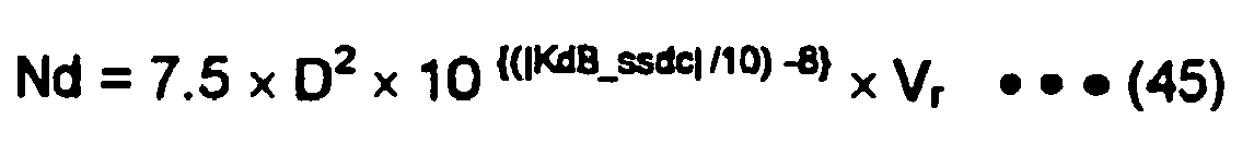
- The above equation (45) is transformed into the following equation (46).

- By transforming the above equation (46), the deceleration target KdB_ssdc is expressed in logarithm in the following equation (47).

- In the above equation (47), as described above, the normal vehicle deceleration Nd is defined as a normal deceleration generated in the vehicle through the drive operation by the driver to decelerate the vehicle. Alternatively, the normal vehicle deceleration Nd may be defined as a deceleration generated in the vehicle by the engine braking.
- At step 430 (S430), it is determined whether the present evaluation index KdB_p is larger than the deceleration target KdB_ssdc. If it is determined that the present evaluation index KdB_p is larger than the deceleration target KdB_ssdc (YES), the control of the braking force is considered to be started, and control proceeds to step 440 (S440). On the other hand, if it is determined that the present evaluation index KdB_p is not larger than the deceleration target KdB_ssdc (NO), control proceeds to S400 and the above processing is repeatedly executed.
- In this manner, the deceleration target KdB_ssdc is calculated based on the normal vehicle deceleration Nd, and the control of the braking force of the brake system is started at the time the present evaluation index KdB_p becomes larger than the deceleration target KdB_ssdc. Accordingly, when the vehicle approaches the road associated object, the control of the braking force of the brake system can be started with a timing, with which the driver normally starts the drive operation to decelerate the vehicle even if the driver does not start the drive operation to decelerate the vehicle.
- At S440, the target value KdB_t of the evaluation index KdB is calculated. The method of calculating the target evaluation index KdB_t has been described in the third embodiment with reference to
FIG. 16 . The target evaluation index KdB_t, which increases linearly at the constant slope when the distance to the road associated object decreases, is set at S440. Consequently, the vehicle can be decelerated such that the degree of reduction in the relative speed between the vehicle and the road associated object increases when the vehicle approaches the road associated object. As a result, the driver can feel a satisfactory sense of deceleration. - At step 450 (S450), the target relative speed Vr-t is calculated by the following equation (48) using the target evaluation index KdB_t, which is calculated at S440.

- That is, the approaching/separating state evaluation index curve, which passes through the target evaluation index KdB_t with the distance D being the present distance Dp to the road associated object (
FIG. 16 ), is assumed. Then, a relative speed is obtained from the assumed curve as the target relative speed Vr_t. - At step 460 (S460), by differentiating the present distance Dp, the target relative deceleration dVr/dt_t is calculated by the following equation (49) using the present relative speed Vr_p between the vehicle and the road associated object and the target relative speed Vr_t.

- Additionally, Δt is a divisor to convert a difference between the present relative speed Vr_p and the target relative speed Vr_t into the target relative deceleration dVr/dt_t, and is appropriately set.
- At step 470 (S470), it is determined whether the collision time allowance TTC that expresses a time allowance before the vehicle collides with the road associated object is shorter than the predetermined amount of time Tref. If it is determined that the collision time allowance TTC is shorter than the predetermined amount of time Tref (TTC < Tref) at S470, control proceeds to step 480 (S480), whereas control proceeds to step 490 (S490) if it is determined that the collision time allowance TTC is equal to or longer than the predetermined amount of time Tref (TTC ≥ Tref).
- In addition, if it is determined that the collision time allowance TTC is equal to or longer than the predetermined amount of time Tref (TTC ≥ Tref), there is an enough collision time allowance TTC at the time it is determined that the present evaluation index KdB_p is larger than the deceleration target KdB_ssdc. Accordingly, it is considered that the collision with the road associated object can be readily avoided through the driver's own drive operation. Thus, the control of the braking force by the present vehicle brake control system is not carried out at S490.
- At S480, the control of the braking force is carried out. That is, the control of the braking force is carried out when the collision time allowance TTC before the vehicle collides with the road associated object is shorter than the predetermined amount of time Tref, and the vehicle cannot be decelerated with the target relative deceleration dVr /dt_t through the driver's own drive operation.
- The control of the braking force at S480 may be carried out as follows. That is, the brake pressure to generate the target relative deceleration dVr/dt_t calculated at S460 is obtained from a prepared map, and the
brake actuator 370 is controlled to generate this brake pressure. Alternatively, the actual deceleration of the vehicle is detected, and thebrake actuator 370 regulates the brake pressure, such that this actual deceleration reaches the target relative deceleration dVr/dt_t. - At step 500 (S500), it is determined whether a condition for termination of the control of the braking force is met. This condition may be met, for example, when the vehicle is stopped, or the present evaluation index KdB_p is smaller than the target evaluation index KdB_t by a designated value or more. If the condition is not met, the processing is repeatedly executed from S400.
- The vehicle brake control system according to the fourth embodiment calculates the deceleration target based on the normal vehicle deceleration, and starts the control of the braking force of the brake system at the time the approaching/separating state evaluation index becomes larger than the deceleration target. Accordingly, when the vehicle proceeds into the curve or travels along the curve, the control of the braking force of the brake system can be started with a timing, with which the driver normally starts the drive operation to decelerate the vehicle even if the driver does not start the drive operation to decelerate the vehicle. As a result, the driver can be assisted with his/her drive operation of the vehicle in a comprehensive manner when the vehicle travels along the curve.
- When the control of the braking force of the brake system is started, the target approaching/separating state evaluation index, which increases linearly at the constant slope when the distance to the road associated object decreases, is set. When the distance to the road associated object decreases, the approaching/separating state evaluation index increases at a steeper slope if the relative speed is constant. Thus, by setting the target approaching/separating state evaluation index, which increases linearly at the constant slope when the distance to the road associated object decreases, the vehicle can be decelerated such that the degree of reduction in the relative speed between the vehicle and the road associated object increases when the vehicle approaches the road associated object.
- In addition, the constant slope that is used for calculating the target approaching/separating state evaluation index varies according to the distance to the road associated object at the time of the starting of the drive operation to decelerate the vehicle by the driver. Thus, the target approaching/separating state evaluation index, which is appropriate for the distance to the road associated object and the relative speed between the vehicle and the road associated object, can be set.
- Additional advantages and modifications will readily occur to those skilled in the art. The invention in its broader terms is therefore not limited to the specific details, representative apparatus, and illustrative examples shown and described.
Claims (20)
- A vehicle control system for controlling a vehicle, comprising:- a distance obtaining means (100) for obtaining a distance (D) between the vehicle and a road associated object (M1 to M6) on a road, wherein the road associated object (M1 to M6) is an object located along an extension line of a traveling direction of the vehicle, and at a boundary of a curve of the road or in a vicinity of the boundary, wherein the curve exists ahead of the vehicle;- an evaluation index calculating means (110) for calculating an approaching/separating state evaluation index (KdB) that indicates a positional relationship between the vehicle and the road associated object (M1 to M6), wherein:- the approaching/separating state evaluation index (KdB) increases when a relative speed. (Vr) between the vehicle and the road associated object (M1 to M6) increases at a time of approaching of the vehicle to the road associated object (M1 to M6);- the approaching/separating state evaluation index (KdB) for the relative speed (Vr) increases at a faster rate as the distance (D) decreases; and- the approaching/separating state evaluation index (KdB) is obtained based on a degree of variation per unit time (dS/dt) in an area (S) of an image of the road associated object (M1 to M6) projected on an eye of a driver of the vehicle;- a curvature radius obtaining means (204) for obtaining a curvature radius (R) of the curve;- a target vehicle speed setting means (100) for setting a target vehicle speed (Vs0_t) of the vehicle, with which the vehicle travels along the curve, based on the curvature radius (R) of the curve;- a vehicle speed obtaining means (100) for obtaining a current speed (Vs0) of the vehicle;- a target vehicle acceleration/deceleration calculating means (206) for calculating a target vehicle acceleration or deceleration (dVs0/dt), with which the vehicle is controlled to travel so that the vehicle travels along the curve with the target vehicle speed 0/s0_t), based on the approaching/separating state evaluation index (KdB), the distance (D), the current speed (Vs0) of the vehicle, and the target vehicle speed (Vs0_t); and- a vehicle control means (100) for controlling the vehicle such that an acceleration or deceleration of the vehicle coincides with the target vehicle acceleration or deceleration (dVs0/dt), respectively, based on a comparison between the current speed (Vs0) of the vehicle and the target vehicle speed (Vs0_t).
- A vehicle control system for controlling a vehicle, comprising:- a distance obtaining means (100) for obtaining a distance (D) between the vehicle and an obstruction on a road, wherein the obstruction exists on the road, which is ahead of the vehicle in a traveling direction of the vehicle;- a relative speed obtaining means (130) for obtaining a relative speed (Vr) between the vehicle and the obstruction;- an evaluation index calculating means (110) for calculating an approaching/separating state evaluation index (KdB) that indicates a positional relationship between the vehicle and the obstruction, wherein:- the approaching/separating state evaluation index (KdB) increases when the relative speed (Vr) increases at a time of approaching of the vehicle to the obstruction;- the approaching/separating state evaluation index (KdB) for the relative speed (Vr) increases at a faster rate as the distance (D) decreases; and- the approaching/separating state evaluation index (KdB) is obtained based on a degree of variation per unit time (dS/dt) in an area (S) of an image of the obstruction projected on an eye of a driver of the vehicle;- a turning radius calculating means (208) for calculating a turning radius (R0) of the vehicle, which is necessary for the vehicle to avoid a collision with the obstruction, based on the distance (D);- a target lateral acceleration setting means (209) for setting a target value (Gyo) of a lateral acceleration, which is generated in the vehicle in a lateral direction of the vehicle through a steering operation by a driver of the vehicle to avoid the collision;- a target relative speed calculating means (210) for calculating a target relative speed (Vr_t) between the vehicle and the obstruction based on the turning radius (R0) and the target value (Gyo) of the lateral acceleration;- a target relative deceleration calculating means (211) for calculating a target relative deceleration (dVr/dt) between the vehicle and the obstruction based on the distance (D), the relative speed (Vr), and the approaching/separating state evaluation index (KdB); and- a vehicle control means (100) for controlling the vehicle to decelerate such that a relative deceleration between the vehicle and the obstruction coincides with the target relative deceleration (dVr/dt) when the relative speed (Vr) is larger than the target relative speed Vr_t), wherein the vehicle is controlled to travel with the target relative deceleration (dVr/dt) by the vehicle control means (100) so that the vehicle is decelerated to the target relative speed (Vr_t).
- The vehicle control system according to claim 1 or 2, wherein the vehicle control means (100) controls the vehicle to decelerate such that the deceleration of the vehicle coincides with the target vehicle deceleration (dVs0/dt) when the current speed (Vs0) of the vehicle is larger than the target vehicle speed (Vs0_t), and controls the vehicle to accelerate such that the acceleration of the vehicle coincides with the target vehicle acceleration (dVs0/dt) when the current speed (Vs0) of the vehicle is smaller than the target vehicle speed (Vs0_t).
- The vehicle control system according to claim 1, 2 or 3, wherein the vehicle control means (100) controls the vehicle to maintain the current speed (Vs0) of the vehicle when a difference between the current speed (Vs0) of the vehicle and the target vehicle speed (Vs0_t) is smaller than a predetermined value.
- The vehicle control system according to any one of claims 1 to 4, wherein the evaluation index calculating means (110) calculates KdB_p, which is a present value (KdB_p) of the approaching/separating state evaluation index (KdB) between the vehicle and the road associated object (M1 to M6), using the following equation, given Vs0, which is the current speed (Vs0) of the vehicle, and D, which is the distance (D) between the vehicle and the road associated object (M1 to M6):

- The vehicle control system according to claim 5, wherein the target vehicle acceleration/deceleration calculating means (206) calculates dVs0/dt, which is the target vehicle acceleration or deceleration (dVs0/dt), using the following equation, given Vs0_t, which is the target vehicle speed (Vs0_t):

- The vehicle control system according to claim 6, wherein the target vehicle acceleration/deceteration calculating means (206) calculates a final value of the target vehicle acceleration or deceleration (dVs0/dt) by multiplying the target vehicle acceleration or deceleration (dVs0/dt) by gain, which is a positive value and is equal to or smaller than one.
- The vehicle control system according to any one of claims 1 and 3 to 7, wherein the distance obtaining means (100) obtains the distance (D) between the vehicle and the road associated object (M1 to M6), wherein the road associated object (M1 to M6) includes at least one of a lane marking (M1), a pole (M2), a guardrail (M3), a curbstone (M4), a reflective plate (M5), and a delineator (M6).
- The vehicle control system according to any one of claims 1 and 3 to 7, wherein the distance obtaining means (100) obtains the distance (D) between the vehicle and the road associated object (M1 to M6) using road map data and a position of the vehicle, which is detected by a global positioning system.
- The vehicle control system according to any one of claims 1 to 9, wherein the target relative deceleration calculating means (211) calculates a final value of the target relative deceleration (dVr/dt) by multiplying the target relative deceleration (dVr /dt) by gain, which is a positive value and is equal to or smaller than one.
- The vehicle control system according to any one of claims 1 to 10, further comprising:- a road surface friction coefficient determining means (202) for determining a friction coefficient (µ) between a tire of the vehicle and a surface of the road that is ahead of the vehicle in the traveling direction of the vehicle; and- a maximum deceleration calculating means (211) for calculating a maximum deceleration that is generable in the vehicle based on the friction coefficient (µ), wherein the vehicle control means (100) controls the vehicle such that the relative deceleration between the vehicle and the obstruction is smaller than the maximum deceleration.
- The vehicle control system according to any one of claims 1 to 11, further comprising a vehicle projection plane locus estimating means (130) for estimating a future locus of a projection plane of the vehicle based on a traveling state of the vehicle, wherein:- the projection plane of the vehicle is a plane that has an area of a width (Ws) and height (Hs) of the vehicle; and- the future locus of the projection plane is a virtual three-dimensional track left by the projection plane along the road when it is hypothesized that the projection plane travels with a present traveling state of the vehicle maintained, wherein the distance obtaining means (100) obtains the distance (D) between the vehicle and the obstruction, which overlaps with the future locus of the projection plane of the vehicle.
- The vehicle control system according to claim 12, wherein the vehicle projection plane locus estimating means (130) estimates the future locus of the projection
plane of the vehicle in view of a minimum ground clearance (hg) of the vehicle. - The vehicle control system according to any one of claims 1 to 13, wherein the evaluation index calculating means (110) calculates KdB_p, which is a present value (KdB_p) of the approaching/separating state evaluation index (KdB) between the vehicle and the obstruction, using the following equation, given Vr, which is the relative speed (Vr) between the vehicle and the obstruction, and D, which is the distance (D) between the vehicle and the obstruction:

- The vehicle control system according to claim 14, wherein the target relative deceleration calculating means (211) calculates dVr/dt, which is the target relative deceleration (dVr/dt), using the following equation, given Vr_t, which is the target relative speed (Vr_t):

- A vehicle control system according to claim 1 or 2, further comprising:- a deceleration target calculating means (360) for calculating a deceleration target (KdB_ssdc) based on a normal deceleration (Nd) of the vehicle, the distance (D), and the relative speed (Vr), wherein the deceleration target (KdB_ssdc) indicates an index of a timing, with which braking force applied through a brake system of the vehicle when the vehicle proceeds into the curve or travels along the curve is controlled;- a deceleration target determining means (360) for determining whether the approaching/separating state evaluation index (KdB) is larger than the deceleration target (KdB_ssdc);- a target value setting means (360) for setting a target value (KdB_t) of the approaching/separating state evaluation index (KdB), such that the target value (KdB_t) of the approaching/separating state evaluation index (KdB) increases linearly from an initial value (KdB0) at a constant slope (S) when the distance (D) decreases, wherein:- the initial value (KdB0) is the approaching/separating state evaluation index (KdB) at a time when the deceleration target determining means (360) determines that the approaching/separating state evaluation index (KdB) is larger than the deceleration target (KdB_ssdc); and- the constant slope (S) is a slope of the approaching/separating state evaluation index (KdB) at the time when the deceleration target determining means (360) determines that the approaching/separating state evaluation index (KdB) is larger than the deceleration target (KdB_ssdc);- a target vehicle deceleration calculating means (360) for calculating a target vehicle deceleration (dVr/dt_t) based on a target relative speed (Vr_t) between the vehicle and the road associated object (M1 to M6), and a present relative speed (Vr_p) between the vehicle and the road associated object (M1 to M6), wherein the target relative speed (Vr_j) is obtained based on the target value (KdB_t) of the approaching/separating state evaluation index (KdB); and- a braking force control means (360) for controlling the braking force applied through the brake system such that a deceleration (dVr/dt_dr) of the vehicle coincides with the target vehicle deceleration (dvr/dt_t) when the vehicle proceeds into the curve or travels along the curve.
- A vehicle control system according to any one of claims 1, 2 or 16, wherein:- the initial value (KdB0) is the approaching/separating state evaluation index (KdB) at a time when a driver of the vehicle starts a drive operation to decelerate the vehicle when the vehicle proceeds into the curve or travels along the curve; and- the constant slope (S) is a slope of the approaching/separating state evaluation index (KdB) at the time when the driver starts the drive operation to decelerate the vehicle;
- the vehicle control system according to claim 17, further comprising a deceleration estimating means (360) for estimating the deceleration (dVr/dt_dr) of the vehicle, which is generated through the drive operation by the driver to decelerate the vehicle, wherein the braking force control means (360) does not control the braking force when the deceleration (dVr/dt_dr) of the vehicle is larger than the target vehicle deceleration (dVr/dt_t).
- The vehicle control system according to any one of claims 16 to 18, further comprising a collision time allowance calculating means (360) for calculating a collision time allowance (TTC) that indicates a time allowance before the vehicle collides with the road associated object (M1 to M6), wherein the braking force control means (360) does not control the braking force when the collision time allowance (TTC) is equal to or longer than a predetermined amount of time.
- The vehicle control system according to any one of claims 16 to 19, wherein the target value setting means (360) multiplies the slope of the approaching/separating state evaluation index (KdB) by gain, which is determined by a driver of the vehicle, and sets the target value (KdB_t) of the approaching/separating state evaluation index (KdB) using the slope multiplied by the gain.
Applications Claiming Priority (3)
| Application Number | Priority Date | Filing Date | Title |
|---|---|---|---|
| JP2006035566 | 2006-02-13 | ||
| JP2006130631 | 2006-05-09 | ||
| JP2006228374A JP4169065B2 (en) | 2006-02-13 | 2006-08-24 | Vehicle control device |
Publications (3)
| Publication Number | Publication Date |
|---|---|
| EP1818231A2 EP1818231A2 (en) | 2007-08-15 |
| EP1818231A3 EP1818231A3 (en) | 2008-06-04 |
| EP1818231B1 true EP1818231B1 (en) | 2012-05-02 |
Family
ID=38036410
Family Applications (1)
| Application Number | Title | Priority Date | Filing Date |
|---|---|---|---|
| EP07002197A Active EP1818231B1 (en) | 2006-02-13 | 2007-02-01 | Vehicle control system |
Country Status (4)
| Country | Link |
|---|---|
| US (1) | US7433772B2 (en) |
| EP (1) | EP1818231B1 (en) |
| JP (1) | JP4169065B2 (en) |
| CN (1) | CN101020453B (en) |
Families Citing this family (90)
| Publication number | Priority date | Publication date | Assignee | Title |
|---|---|---|---|---|
| US7272482B2 (en) * | 2002-09-30 | 2007-09-18 | Nissan Motor Co., Ltd. | Preceding-vehicle following control system |
| JP4169065B2 (en) * | 2006-02-13 | 2008-10-22 | 株式会社デンソー | Vehicle control device |
| JP4912775B2 (en) * | 2006-07-14 | 2012-04-11 | 本田技研工業株式会社 | Vehicle travel safety device |
| DE102007040539B4 (en) * | 2006-09-04 | 2014-03-27 | Denso Corporation | Vehicle control system |
| EP1961639A1 (en) * | 2007-02-22 | 2008-08-27 | Nederlandse Organisatie voor toegepast- natuurwetenschappelijk onderzoek TNO | Vehicle driving assistance |
| JP4938542B2 (en) * | 2007-04-27 | 2012-05-23 | トヨタ自動車株式会社 | Vehicle speed control device for vehicle |
| JP4412356B2 (en) * | 2007-06-13 | 2010-02-10 | 株式会社デンソー | Vehicle collision mitigation device |
| JP4497231B2 (en) * | 2007-10-09 | 2010-07-07 | 株式会社デンソー | Vehicle speed control device |
| JP4995029B2 (en) * | 2007-10-18 | 2012-08-08 | 富士重工業株式会社 | Vehicle driving support device |
| US8126626B2 (en) * | 2008-01-30 | 2012-02-28 | GM Global Technology Operations LLC | Vehicle path control for autonomous braking system |
| US8457359B2 (en) | 2008-02-20 | 2013-06-04 | Continental Teves Ag & Co. Ohg | Method and assistance system for detecting objects in the surrounding area of a vehicle |
| JP2009286279A (en) * | 2008-05-29 | 2009-12-10 | Fuji Heavy Ind Ltd | Drive support device for vehicle |
| JP5206138B2 (en) * | 2008-06-12 | 2013-06-12 | 日産自動車株式会社 | Vehicle deceleration control device |
| JP4602444B2 (en) * | 2008-09-03 | 2010-12-22 | 株式会社日立製作所 | Driver driving skill support apparatus and driver driving skill support method |
| JP5139939B2 (en) * | 2008-09-25 | 2013-02-06 | 日立オートモティブシステムズ株式会社 | Vehicle deceleration support device |
| US8359149B2 (en) * | 2009-02-03 | 2013-01-22 | GM Global Technology Operations LLC | Method for integrating multiple feature adaptive cruise control |
| EP2404803A4 (en) * | 2009-03-06 | 2016-08-10 | Toyota Motor Co Ltd | Vehicle travel control device |
| JP5075152B2 (en) * | 2009-03-24 | 2012-11-14 | 日立オートモティブシステムズ株式会社 | Vehicle control device |
| JP5376223B2 (en) * | 2009-05-18 | 2013-12-25 | アイシン精機株式会社 | Driving assistance device |
| JP5363906B2 (en) * | 2009-08-05 | 2013-12-11 | 株式会社アドヴィックス | Vehicle speed control device |
| WO2011074115A1 (en) | 2009-12-18 | 2011-06-23 | トヨタ自動車株式会社 | Travel control device |
| DE102011014139B4 (en) * | 2010-03-17 | 2023-04-06 | Hl Klemove Corp. | METHOD AND SYSTEM FOR A LANE KEEPING CONTROL |
| US9156447B2 (en) | 2010-05-28 | 2015-10-13 | GM Global Technology Operations LLC | Methods and apparatus for a vehicle emergency control system |
| US9376095B2 (en) | 2010-07-22 | 2016-06-28 | GM Global Technology Operations LLC | Methods and apparatus for determining tire/road coefficient of friction |
| US9280711B2 (en) | 2010-09-21 | 2016-03-08 | Mobileye Vision Technologies Ltd. | Barrier and guardrail detection using a single camera |
| DE102010051203B4 (en) * | 2010-11-12 | 2022-07-28 | Zf Active Safety Gmbh | Method for detecting critical driving situations in trucks or passenger vehicles, in particular for avoiding collisions |
| DE102011017588A1 (en) * | 2011-04-27 | 2012-10-31 | Robert Bosch Gmbh | Method for automatically decelerating a vehicle |
| WO2013046299A1 (en) * | 2011-09-26 | 2013-04-04 | トヨタ自動車株式会社 | Vehicle driving assistance system |
| US9085237B2 (en) * | 2011-10-03 | 2015-07-21 | Fuji Jukogyo Kabushiki Kaisha | Speed limiter |
| DE102011085140A1 (en) | 2011-10-25 | 2013-04-25 | Robert Bosch Gmbh | Method and control unit for operating a vehicle dynamics control of a vehicle and control system for vehicle dynamics control of a vehicle using environmental sensing data |
| CN102568218B (en) * | 2011-12-09 | 2013-09-18 | 东南大学 | Method for determining safe running speed on expressway under crosswind |
| JP5923973B2 (en) * | 2011-12-26 | 2016-05-25 | 株式会社豊田中央研究所 | Route correction device |
| EP2618108B1 (en) * | 2012-01-19 | 2018-10-17 | Volvo Car Corporation | Driver assisting system |
| KR20140107605A (en) * | 2012-01-25 | 2014-09-04 | 도요타 지도샤(주) | Vehicle control device |
| JP5916444B2 (en) * | 2012-03-08 | 2016-05-11 | 日立建機株式会社 | Mining vehicle |
| CN104245462B (en) * | 2012-04-19 | 2016-10-05 | 丰田自动车株式会社 | The driving assist system of vehicle, pavement friction condition estimating system |
| DE102012209519B4 (en) * | 2012-06-06 | 2015-01-08 | Saf-Holland Gmbh | Method for ensuring the braking effect of a brake |
| JP5842740B2 (en) * | 2012-06-13 | 2016-01-13 | 株式会社アドヴィックス | Vehicle travel support device |
| JP5944781B2 (en) * | 2012-07-31 | 2016-07-05 | 株式会社デンソーアイティーラボラトリ | Mobile object recognition system, mobile object recognition program, and mobile object recognition method |
| GB201215963D0 (en) * | 2012-09-06 | 2012-10-24 | Jaguar Cars | Vehicle control system and method |
| CN104768822B (en) * | 2012-09-20 | 2017-04-19 | 谷歌公司 | method and system for detecting road weather conditions |
| JP5764111B2 (en) * | 2012-11-22 | 2015-08-12 | 富士重工業株式会社 | Brake pressure control device for vehicle |
| EP2927082B1 (en) * | 2012-11-27 | 2017-08-02 | Nissan Motor Co., Ltd | Vehicule acceleration suppression device and vehicle acceleration suppression method |
| US9776587B2 (en) * | 2012-11-29 | 2017-10-03 | Here Global B.V. | Method and apparatus for causing a change in an action of a vehicle for safety |
| US10908417B2 (en) * | 2013-09-19 | 2021-02-02 | Magna Electronics Inc. | Vehicle vision system with virtual retinal display |
| CN105593089B (en) * | 2013-09-30 | 2018-01-05 | 日立汽车系统株式会社 | The travel controlling system of vehicle |
| WO2015083009A1 (en) | 2013-12-04 | 2015-06-11 | Mobileye Vision Technologies Ltd. | Systems and methods for mimicking a leading vehicle |
| KR101534958B1 (en) * | 2013-12-09 | 2015-07-07 | 현대자동차주식회사 | Apparatus and Method for Controlling of Automatic Steering of Vehicle |
| JP5947279B2 (en) * | 2013-12-20 | 2016-07-06 | 株式会社デンソー | Course estimation device and program |
| JP6206258B2 (en) * | 2014-03-06 | 2017-10-04 | 富士通株式会社 | Trajectory estimation device, trajectory estimation method, and program |
| SE539599C2 (en) * | 2014-05-21 | 2017-10-17 | Scania Cv Ab | Method and system for adapting a vehicle's acceleration when driving the vehicle along a route |
| JP6183298B2 (en) * | 2014-06-10 | 2017-08-23 | 株式会社デンソー | Collision avoidance device |
| CN105444772A (en) * | 2014-08-22 | 2016-03-30 | 环达电脑(上海)有限公司 | Navigation apparatus and method thereof |
| CN105374231A (en) * | 2014-08-27 | 2016-03-02 | 中国移动通信集团公司 | Early warning method, device and system |
| DE102014225804A1 (en) * | 2014-12-15 | 2016-06-16 | Bayerische Motoren Werke Aktiengesellschaft | Assistance in driving a vehicle |
| JP6298772B2 (en) * | 2015-01-14 | 2018-03-20 | 日立オートモティブシステムズ株式会社 | In-vehicle control device, own vehicle position and orientation identification device, in-vehicle display device |
| JP6443063B2 (en) * | 2015-01-15 | 2018-12-26 | 株式会社デンソー | Road shape information generation apparatus, road shape information collection and delivery system, and road shape information generation program |
| JP6181678B2 (en) * | 2015-01-29 | 2017-08-16 | トヨタ自動車株式会社 | Vehicle braking control device |
| CN104670191B (en) * | 2015-02-09 | 2017-09-22 | 浙江吉利汽车研究院有限公司 | Automatic emergency brake method and apparatus |
| CN104751158A (en) * | 2015-03-11 | 2015-07-01 | 广西科技大学 | Visual identifying method for road barriers in surface mining area |
| US20160378112A1 (en) * | 2015-06-26 | 2016-12-29 | Intel Corporation | Autonomous vehicle safety systems and methods |
| CN105172791A (en) * | 2015-10-30 | 2015-12-23 | 东风汽车公司 | Smart self-adaptive cruise control method |
| JP2017100653A (en) * | 2015-12-04 | 2017-06-08 | 株式会社デンソー | Travel control device |
| CN108474848A (en) | 2015-12-10 | 2018-08-31 | 深圳市大疆创新科技有限公司 | system and method for mobile platform operation |
| JP6460033B2 (en) * | 2016-04-11 | 2019-01-30 | 株式会社デンソー | Vehicle control device |
| CN106114558B (en) * | 2016-06-29 | 2017-12-01 | 南京雅信科技集团有限公司 | Suitable for the preceding tail-light detection method of subway tunnel bending section |
| US10124802B2 (en) * | 2016-08-20 | 2018-11-13 | Toyota Motor Engineering & Manufacturing North America, Inc. | Controlled vehicle deceleration based on a selected vehicle driving mode |
| WO2018042671A1 (en) * | 2016-09-05 | 2018-03-08 | 日産自動車株式会社 | Vehicle travel control method and vehicle travel control device |
| CN107918113B (en) * | 2016-09-07 | 2020-03-20 | 清华大学 | Combined vehicle-mounted radar calibration method |
| JP6659513B2 (en) * | 2016-10-05 | 2020-03-04 | 本田技研工業株式会社 | Vehicle control device, vehicle control method, and vehicle control program |
| JP6848320B2 (en) * | 2016-10-06 | 2021-03-24 | 富士ゼロックス株式会社 | Underwater mobile |
| KR20180059224A (en) * | 2016-11-25 | 2018-06-04 | 현대자동차주식회사 | Apparatus for controlling stop of vehicle and method thereof |
| US11180141B2 (en) * | 2016-12-05 | 2021-11-23 | Mazda Motor Corporation | Vehicle control system |
| CN106945663B (en) * | 2017-04-13 | 2020-09-25 | 大陆投资(中国)有限公司 | Anti-collision method for turning vehicle |
| EP3413082B1 (en) * | 2017-06-09 | 2020-01-01 | Veoneer Sweden AB | A vehicle system for detection of oncoming vehicles |
| US10875530B2 (en) | 2017-08-30 | 2020-12-29 | Nissan Motor Co., Ltd. | Travel control method and travel control device for drive-assisted vehicle |
| JP6965739B2 (en) * | 2017-12-27 | 2021-11-10 | 株式会社デンソー | Vehicle control device |
| GB2572448B (en) * | 2018-03-30 | 2021-02-03 | Jaguar Land Rover Ltd | Vehicle control method and apparatus |
| WO2019195415A1 (en) * | 2018-04-03 | 2019-10-10 | Mobileye Vision Technologies Ltd. | Systems and methods for determining navigational parameters |
| US10678249B2 (en) | 2018-04-20 | 2020-06-09 | Honda Motor Co., Ltd. | System and method for controlling a vehicle at an uncontrolled intersection with curb detection |
| CN108549391B (en) * | 2018-05-25 | 2021-11-19 | 汇专科技集团股份有限公司 | AGV trolley control system and method |
| US10596959B1 (en) | 2018-10-04 | 2020-03-24 | Douglas Gary DeWalt | System and method for signaling vehicle speed and rapid deceleration utilizing tail lights |
| JP7127489B2 (en) | 2018-10-31 | 2022-08-30 | 株式会社デンソー | vehicle controller |
| CN112810610A (en) * | 2019-10-30 | 2021-05-18 | 北京新能源汽车股份有限公司 | Curve driving control method, device and equipment and automobile |
| KR20210062143A (en) * | 2019-11-20 | 2021-05-31 | 현대자동차주식회사 | Apparatus for displaying steering information of preceding vehicle and method thereof |
| CN110992710B (en) * | 2019-12-13 | 2021-03-16 | 潍柴动力股份有限公司 | Curve speed measurement early warning method and device, control equipment and readable storage medium |
| CN111332264B (en) * | 2020-03-18 | 2021-04-27 | 东风汽车集团有限公司 | Automatic emergency braking control method and system |
| CN113232648A (en) * | 2021-04-15 | 2021-08-10 | 江苏大学 | Automobile collision avoidance system for weak road users and control method thereof |
| CN113386793B (en) * | 2021-06-30 | 2022-06-03 | 重庆长安汽车股份有限公司 | Linear and nonlinear control combined low-speed steady-state control system |
| CN116620287B (en) * | 2023-06-30 | 2024-03-19 | 南京项尚车联网技术有限公司 | Intelligent driving method and system |
Family Cites Families (31)
| Publication number | Priority date | Publication date | Assignee | Title |
|---|---|---|---|---|
| US4366546A (en) * | 1979-09-07 | 1982-12-28 | Hitachi, Ltd. | Signal processor for skid control device |
| JPH0810027B2 (en) * | 1986-04-10 | 1996-01-31 | 本田技研工業株式会社 | Control method of clutch for fluid torque converter in vehicle transmission |
| DE4408745C2 (en) * | 1993-03-26 | 1997-02-27 | Honda Motor Co Ltd | Driving control device for vehicles |
| JP2799375B2 (en) * | 1993-09-30 | 1998-09-17 | 本田技研工業株式会社 | Anti-collision device |
| US5586028A (en) * | 1993-12-07 | 1996-12-17 | Honda Giken Kogyo Kabushiki Kaisha | Road surface condition-detecting system and anti-lock brake system employing same |
| US5661650A (en) * | 1994-02-23 | 1997-08-26 | Honda Giken Kogyo Kabushiki Kaisha | System for controlling a vehicle relative to a judged shape of a travel road |
| JP3432881B2 (en) * | 1994-02-23 | 2003-08-04 | 本田技研工業株式会社 | Vehicle control device |
| US5854987A (en) * | 1995-02-22 | 1998-12-29 | Honda Giken Kogyo Kabushiki Kaisha | Vehicle steering control system using navigation system |
| JPH08263793A (en) * | 1995-03-23 | 1996-10-11 | Honda Motor Co Ltd | Vehicle controller |
| EP0810363B1 (en) * | 1996-05-28 | 2004-07-28 | Matsushita Electric Industrial Co., Ltd. | Air/fuel ratio control apparatus that uses a neural network |
| JP3511844B2 (en) * | 1996-08-29 | 2004-03-29 | トヨタ自動車株式会社 | Vehicle running condition prediction device, alarm device using the same, and medium recording prediction data |
| US6003627A (en) * | 1996-08-08 | 1999-12-21 | Nabco Limited | Motor-driven vehicle control apparatus |
| JP4308927B2 (en) * | 1996-11-21 | 2009-08-05 | ナブテスコ株式会社 | Electric vehicle |
| JPH10238372A (en) * | 1997-02-27 | 1998-09-08 | Aisan Ind Co Ltd | Throttle valve controller |
| JP3388132B2 (en) * | 1997-04-09 | 2003-03-17 | 本田技研工業株式会社 | Vehicle control device |
| JPH1185719A (en) * | 1997-09-03 | 1999-03-30 | Matsushita Electric Ind Co Ltd | Parameter estimation device |
| US6138071A (en) * | 1997-09-16 | 2000-10-24 | Honda Giken Kogyo Kabushiki Kaisha | Cruising control apparatus |
| JP4037506B2 (en) * | 1998-03-12 | 2008-01-23 | 富士重工業株式会社 | Vehicle motion control device |
| JP3998855B2 (en) * | 1999-05-18 | 2007-10-31 | 三菱電機株式会社 | Dangerous approach prevention device |
| JP3391745B2 (en) | 1999-09-22 | 2003-03-31 | 富士重工業株式会社 | Curve approach control device |
| JP3783562B2 (en) * | 2000-12-28 | 2006-06-07 | 日産自動車株式会社 | Vehicle travel control device |
| JP4572469B2 (en) * | 2001-01-23 | 2010-11-04 | 株式会社アドヴィックス | Hydraulic brake device for vehicle |
| JP3793431B2 (en) | 2001-07-23 | 2006-07-05 | 本田技研工業株式会社 | Auto cruise control device |
| JP3912104B2 (en) * | 2001-12-25 | 2007-05-09 | 三菱自動車工業株式会社 | Engine cooling system |
| JP3986939B2 (en) * | 2002-10-25 | 2007-10-03 | 本田技研工業株式会社 | Brake device for vehicle |
| JP4267294B2 (en) * | 2002-11-05 | 2009-05-27 | トヨタ自動車株式会社 | Brake control device for vehicle |
| US6970779B2 (en) * | 2002-11-25 | 2005-11-29 | Denso Corporation | Vehicle speed control system and program |
| JP4425549B2 (en) | 2003-01-28 | 2010-03-03 | 日産自動車株式会社 | Deceleration control device |
| JP3890597B2 (en) | 2003-09-30 | 2007-03-07 | マツダ株式会社 | Vehicle information providing device |
| JP2006001369A (en) * | 2004-06-16 | 2006-01-05 | Denso Corp | Driving situation determination device |
| JP4169065B2 (en) * | 2006-02-13 | 2008-10-22 | 株式会社デンソー | Vehicle control device |
-
2006
- 2006-08-24 JP JP2006228374A patent/JP4169065B2/en active Active
-
2007
- 2007-02-01 EP EP07002197A patent/EP1818231B1/en active Active
- 2007-02-07 US US11/703,812 patent/US7433772B2/en active Active
- 2007-02-13 CN CN2007100057512A patent/CN101020453B/en active Active
Also Published As
| Publication number | Publication date |
|---|---|
| US20070191997A1 (en) | 2007-08-16 |
| CN101020453B (en) | 2010-05-19 |
| EP1818231A3 (en) | 2008-06-04 |
| CN101020453A (en) | 2007-08-22 |
| EP1818231A2 (en) | 2007-08-15 |
| US7433772B2 (en) | 2008-10-07 |
| JP2007326548A (en) | 2007-12-20 |
| JP4169065B2 (en) | 2008-10-22 |
Similar Documents
| Publication | Publication Date | Title |
|---|---|---|
| EP1818231B1 (en) | Vehicle control system | |
| US20210188356A1 (en) | Vehicle control device | |
| US20210188258A1 (en) | Vehicle control device | |
| US20210188262A1 (en) | Vehicle control device | |
| US20200238980A1 (en) | Vehicle control device | |
| EP3741639A1 (en) | Vehicle control device | |
| US8150591B2 (en) | Vehicle travel speed control method | |
| EP3539838A1 (en) | Vehicle control device | |
| US20200353918A1 (en) | Vehicle control device | |
| EP3715204A1 (en) | Vehicle control device | |
| US20090143951A1 (en) | Forward Collision Avoidance Assistance System | |
| US20130226409A1 (en) | Driving support apparatus and driving support method | |
| EP3741638A1 (en) | Vehicle control device | |
| JP6647361B2 (en) | Vehicle driving support device | |
| US8103424B2 (en) | Inter-vehicle distance control apparatus and method for controlling inter-vehicle distance | |
| US20200180614A1 (en) | Vehicle control device | |
| EP3738849A1 (en) | Vehicle control device | |
| JP3689065B2 (en) | Vehicle travel control device | |
| JP7409204B2 (en) | Vehicle control device | |
| JP4400501B2 (en) | Vehicle travel control device | |
| JP4576922B2 (en) | Vehicle travel control device | |
| US20220176922A1 (en) | Driving assistance system | |
| JP7397609B2 (en) | Driving environment recognition device | |
| US20220212669A1 (en) | Vehicle control device, operation method of vehicle control device, and storage medium |
Legal Events
| Date | Code | Title | Description |
|---|---|---|---|
| PUAI | Public reference made under article 153(3) epc to a published international application that has entered the european phase |
Free format text: ORIGINAL CODE: 0009012 |
|
| AK | Designated contracting states |
Kind code of ref document: A2 Designated state(s): AT BE BG CH CY CZ DE DK EE ES FI FR GB GR HU IE IS IT LI LT LU LV MC NL PL PT RO SE SI SK TR |
|
| AX | Request for extension of the european patent |
Extension state: AL BA HR MK YU |
|
| PUAL | Search report despatched |
Free format text: ORIGINAL CODE: 0009013 |
|
| AK | Designated contracting states |
Kind code of ref document: A3 Designated state(s): AT BE BG CH CY CZ DE DK EE ES FI FR GB GR HU IE IS IT LI LT LU LV MC NL PL PT RO SE SI SK TR |
|
| AX | Request for extension of the european patent |
Extension state: AL BA HR MK RS |
|
| RIC1 | Information provided on ipc code assigned before grant |
Ipc: G08G 1/16 20060101ALI20080430BHEP Ipc: B60K 31/00 20060101ALI20080430BHEP Ipc: B60T 8/1755 20060101AFI20070523BHEP Ipc: B60W 30/08 20060101ALI20080430BHEP Ipc: B60T 7/22 20060101ALI20080430BHEP |
|
| 17P | Request for examination filed |
Effective date: 20081204 |
|
| AKX | Designation fees paid |
Designated state(s): DE FR GB SE |
|
| 17Q | First examination report despatched |
Effective date: 20091008 |
|
| REG | Reference to a national code |
Ref country code: DE Ref legal event code: R079 Ref document number: 602007022339 Country of ref document: DE Free format text: PREVIOUS MAIN CLASS: B60T0008175500 Ipc: B60W0030160000 |
|
| GRAP | Despatch of communication of intention to grant a patent |
Free format text: ORIGINAL CODE: EPIDOSNIGR1 |
|
| RIC1 | Information provided on ipc code assigned before grant |
Ipc: B60W 30/08 20060101ALI20111020BHEP Ipc: B60W 30/16 20060101AFI20111020BHEP Ipc: G08G 1/16 20060101ALI20111020BHEP Ipc: B60T 8/1755 20060101ALI20111020BHEP Ipc: B60W 30/02 20060101ALI20111020BHEP Ipc: B60K 31/00 20060101ALI20111020BHEP Ipc: B60T 7/22 20060101ALI20111020BHEP Ipc: B60W 40/06 20060101ALI20111020BHEP |
|
| RIN1 | Information on inventor provided before grant (corrected) |
Inventor name: TSURU, NAOHIKO Inventor name: ISAJI, KAZUYOSHI |
|
| GRAS | Grant fee paid |
Free format text: ORIGINAL CODE: EPIDOSNIGR3 |
|
| GRAA | (expected) grant |
Free format text: ORIGINAL CODE: 0009210 |
|
| AK | Designated contracting states |
Kind code of ref document: B1 Designated state(s): DE FR GB SE |
|
| REG | Reference to a national code |
Ref country code: GB Ref legal event code: FG4D |
|
| REG | Reference to a national code |
Ref country code: SE Ref legal event code: TRGR |
|
| REG | Reference to a national code |
Ref country code: DE Ref legal event code: R096 Ref document number: 602007022339 Country of ref document: DE Effective date: 20120628 |
|
| REG | Reference to a national code |
Ref country code: GB Ref legal event code: 746 Effective date: 20121206 |
|
| REG | Reference to a national code |
Ref country code: DE Ref legal event code: R084 Ref document number: 602007022339 Country of ref document: DE Effective date: 20121212 |
|
| PLBE | No opposition filed within time limit |
Free format text: ORIGINAL CODE: 0009261 |
|
| STAA | Information on the status of an ep patent application or granted ep patent |
Free format text: STATUS: NO OPPOSITION FILED WITHIN TIME LIMIT |
|
| 26N | No opposition filed |
Effective date: 20130205 |
|
| REG | Reference to a national code |
Ref country code: DE Ref legal event code: R097 Ref document number: 602007022339 Country of ref document: DE Effective date: 20130205 |
|
| REG | Reference to a national code |
Ref country code: FR Ref legal event code: PLFP Year of fee payment: 9 |
|
| REG | Reference to a national code |
Ref country code: FR Ref legal event code: PLFP Year of fee payment: 10 |
|
| REG | Reference to a national code |
Ref country code: FR Ref legal event code: PLFP Year of fee payment: 11 |
|
| REG | Reference to a national code |
Ref country code: FR Ref legal event code: PLFP Year of fee payment: 12 |
|
| PGFP | Annual fee paid to national office [announced via postgrant information from national office to epo] |
Ref country code: FR Payment date: 20230220 Year of fee payment: 17 |
|
| PGFP | Annual fee paid to national office [announced via postgrant information from national office to epo] |
Ref country code: SE Payment date: 20230216 Year of fee payment: 17 Ref country code: GB Payment date: 20230221 Year of fee payment: 17 Ref country code: DE Payment date: 20230216 Year of fee payment: 17 |