EP1818130A1 - Verfahren zum Schneiden einer Öffnung in einer metallischen Platte mit einem Laserstrahl mit Hilfe einer eine Öffnung aufweisenden Schutzplatte - Google Patents
Verfahren zum Schneiden einer Öffnung in einer metallischen Platte mit einem Laserstrahl mit Hilfe einer eine Öffnung aufweisenden Schutzplatte Download PDFInfo
- Publication number
- EP1818130A1 EP1818130A1 EP07290161A EP07290161A EP1818130A1 EP 1818130 A1 EP1818130 A1 EP 1818130A1 EP 07290161 A EP07290161 A EP 07290161A EP 07290161 A EP07290161 A EP 07290161A EP 1818130 A1 EP1818130 A1 EP 1818130A1
- Authority
- EP
- European Patent Office
- Prior art keywords
- aperture
- plate
- contour
- opening
- openings
- Prior art date
- Legal status (The legal status is an assumption and is not a legal conclusion. Google has not performed a legal analysis and makes no representation as to the accuracy of the status listed.)
- Granted
Links
- 238000000034 method Methods 0.000 title claims description 17
- 238000003698 laser cutting Methods 0.000 title abstract description 3
- 229910052751 metal Inorganic materials 0.000 claims abstract description 17
- 239000002184 metal Substances 0.000 claims abstract description 17
- PXHVJJICTQNCMI-UHFFFAOYSA-N Nickel Chemical compound [Ni] PXHVJJICTQNCMI-UHFFFAOYSA-N 0.000 claims abstract description 6
- 230000001681 protective effect Effects 0.000 claims abstract description 6
- 239000000956 alloy Substances 0.000 claims abstract description 3
- 229910045601 alloy Inorganic materials 0.000 claims abstract description 3
- 229910052782 aluminium Inorganic materials 0.000 claims abstract description 3
- XAGFODPZIPBFFR-UHFFFAOYSA-N aluminium Chemical compound [Al] XAGFODPZIPBFFR-UHFFFAOYSA-N 0.000 claims abstract description 3
- 229910052759 nickel Inorganic materials 0.000 claims abstract description 3
- 238000005520 cutting process Methods 0.000 claims description 19
- 238000009826 distribution Methods 0.000 description 6
- 239000007789 gas Substances 0.000 description 4
- 238000004519 manufacturing process Methods 0.000 description 4
- 239000000567 combustion gas Substances 0.000 description 3
- 238000002485 combustion reaction Methods 0.000 description 3
- 230000001012 protector Effects 0.000 description 3
- 239000012530 fluid Substances 0.000 description 2
- 238000003754 machining Methods 0.000 description 2
- 239000000463 material Substances 0.000 description 2
- 230000006866 deterioration Effects 0.000 description 1
- 230000004927 fusion Effects 0.000 description 1
- 239000007788 liquid Substances 0.000 description 1
- 238000002844 melting Methods 0.000 description 1
- 230000008018 melting Effects 0.000 description 1
- 238000005272 metallurgy Methods 0.000 description 1
- 238000004080 punching Methods 0.000 description 1
- 239000007787 solid Substances 0.000 description 1
- 239000003351 stiffener Substances 0.000 description 1
- XLYOFNOQVPJJNP-UHFFFAOYSA-N water Substances O XLYOFNOQVPJJNP-UHFFFAOYSA-N 0.000 description 1
Images

Classifications
-
- F—MECHANICAL ENGINEERING; LIGHTING; HEATING; WEAPONS; BLASTING
- F01—MACHINES OR ENGINES IN GENERAL; ENGINE PLANTS IN GENERAL; STEAM ENGINES
- F01D—NON-POSITIVE DISPLACEMENT MACHINES OR ENGINES, e.g. STEAM TURBINES
- F01D25/00—Component parts, details, or accessories, not provided for in, or of interest apart from, other groups
- F01D25/24—Casings; Casing parts, e.g. diaphragms, casing fastenings
-
- B—PERFORMING OPERATIONS; TRANSPORTING
- B23—MACHINE TOOLS; METAL-WORKING NOT OTHERWISE PROVIDED FOR
- B23K—SOLDERING OR UNSOLDERING; WELDING; CLADDING OR PLATING BY SOLDERING OR WELDING; CUTTING BY APPLYING HEAT LOCALLY, e.g. FLAME CUTTING; WORKING BY LASER BEAM
- B23K26/00—Working by laser beam, e.g. welding, cutting or boring
- B23K26/18—Working by laser beam, e.g. welding, cutting or boring using absorbing layers on the workpiece, e.g. for marking or protecting purposes
-
- B—PERFORMING OPERATIONS; TRANSPORTING
- B23—MACHINE TOOLS; METAL-WORKING NOT OTHERWISE PROVIDED FOR
- B23K—SOLDERING OR UNSOLDERING; WELDING; CLADDING OR PLATING BY SOLDERING OR WELDING; CUTTING BY APPLYING HEAT LOCALLY, e.g. FLAME CUTTING; WORKING BY LASER BEAM
- B23K26/00—Working by laser beam, e.g. welding, cutting or boring
- B23K26/36—Removing material
- B23K26/38—Removing material by boring or cutting
-
- B—PERFORMING OPERATIONS; TRANSPORTING
- B23—MACHINE TOOLS; METAL-WORKING NOT OTHERWISE PROVIDED FOR
- B23K—SOLDERING OR UNSOLDERING; WELDING; CLADDING OR PLATING BY SOLDERING OR WELDING; CUTTING BY APPLYING HEAT LOCALLY, e.g. FLAME CUTTING; WORKING BY LASER BEAM
- B23K2101/00—Articles made by soldering, welding or cutting
- B23K2101/001—Turbines
-
- F—MECHANICAL ENGINEERING; LIGHTING; HEATING; WEAPONS; BLASTING
- F05—INDEXING SCHEMES RELATING TO ENGINES OR PUMPS IN VARIOUS SUBCLASSES OF CLASSES F01-F04
- F05D—INDEXING SCHEME FOR ASPECTS RELATING TO NON-POSITIVE-DISPLACEMENT MACHINES OR ENGINES, GAS-TURBINES OR JET-PROPULSION PLANTS
- F05D2230/00—Manufacture
- F05D2230/10—Manufacture by removing material
- F05D2230/13—Manufacture by removing material using lasers
Definitions
- the present invention relates to the field of cutting metal parts by means of a laser beam, CO2 for example.
- the casing in question is of frustoconical general shape on the inner face of which two coaxial ferrules are fixed whose diameters are not very different. Near the free edge of the outer shell on the one hand and the inner ferrule on the other hand, openings are cut to allow the mounting of fixed vanes fluid distribution. These openings are aligned radially in two.
- the problem is that of cutting the openings on the inner shell.
- the EDM process for example is long and generates a cost of the important piece. In addition, it poses metallurgy problems requiring a mandatory repackaging.
- Wire cutting by its size, is not adapted to the geometry of the part, and the duration generates a significant cost.
- the laser technique is advantageous because of its precision and speed of cutting, but there is the problem of avoiding deterioration of the outer shell when the beam, having passed through the wall of the inner shell is stopped by the wall of the outer shell.
- the outer shell is damaged by the impacts of the laser beam as well as by splashes of molten metal.
- the applicant has therefore set itself the goal of developing a cutting process that solves this problem.
- the cutting method of at least one first aperture by laser beam in a first metal plate in the presence of a second metal plate arranged in parallel, at a short distance from the first plate and having a second aperture whose the contour is at the right of the contour of the openwork to be cut, is characterized in that between the two plates, during the cutting, is provided a plate forming protection means of determined thickness and having a third contour aperture offset inward with respect to the contour of the second aperture.
- the invention eliminates backprojections molten metal because it is discharged through the openings of the protective plate and the second plate.
- the beam is stopped and its residual energy absorbed by the protector. It is also observed that the cutout does not show any burr at the exit of the beam. This process further limits the extent of the thermally affected area. It could be determined to be less than 0.05 mm.
- the method is particularly applicable to cutting a plate in an assembly whose first plate is nickel-based alloy.
- the protection plate is made of aluminum-based metal, and its thickness is between 0.5 and 1.5 mm, especially 1 mm.
- the offset between the contour of the third aperture on the protective plate relative to the contour of the second aperture on the second plate should be less than 0.5 mm, preferably between 0.2 and 0.3 mm., including 0.25 mm.
- the two plates are, first, an inner ferrule and the second, an outer ferrule mounted coaxially inside a turbomachine casing. More particularly, the openings formed on the ferrules form housings for distributor fins.
- the invention is applied to the assembly of the elements of a high pressure distribution casing of a gas turbine engine.
- This is the stator member disposed downstream of the combustion chamber of the engine, comprising an annular channel receiving combustion gases from the combustion chamber and guiding them so as to feed the high pressure turbine wheel disposed.
- the casing 1 during manufacture is fixed on a support S so as to allow the various machining and assembly operations.
- the casing comprises a generally frustoconical portion 3 of axis XX.
- the various elements which together form a part of the stator of the turbomachine are welded or machined thereon.
- the casing comprises in particular two ferrules 5 and 7 coaxial between them an annular channel of axis XX for the combustion gases from the combustion chamber.
- the annular channel communicates on one side with orifices 31 pierced in the wall of the frustoconical part 3.
- the channel is convergent on a certain length, between the portions 51 and 71 of the two rings, and then becomes cylindrical. This latter part is defined by two cylindrical portions 53 and 73.
- the two shells comprise transverse stiffeners, 55 and 75 respectively.
- the free edges 53L and 73L of the two cylindrical portions 53 and 73 are located in the same plane perpendicular to the axis XX.
- an HP turbine wheel is arranged facing the channel and receives the combustion gases that have passed through it.
- Distributor fins are mounted radially between the two cylindrical portions 53 and 73; they are housed between the openings formed in the two portions 53 and 73, and aligned radially in two.
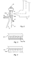
- openings 53a and 73a respectively, as seen in Figure 3, have a substantially rectangular shape with long straight edges inclined relative to the axis XX; connected by rounded edges.
- the ferrules are welded to the inner face of the frustoconical portion at 57 and 77 respectively.
- the crankcase assembly includes the following steps.
- the outer shell 7 is first attached to the housing and welded at 77 and the openings 73a are cut out are the pattern of Figure 3 by means of a laser beam cutting apparatus, this is a laser type CO2 but others are likely to agree.
- the laser cutting head L is shown in Figures 1 and 2. It is supported and controlled by means not shown but known per se.
- the ferrule 5 is welded on the housing along line 57. The relative position of the two ferrules is determined according to the considerations related to the manufacture of the engine and defined elsewhere.
- the difference in radius between the two rings at 53 and 73 is less than 15 mm; it is practically of the order of 4 to 5 mm.
- the cutting head L For the cutting of the openings 53a, one drives in the same way the cutting head L.
- This means is in the form of ferrule or plate depending on whether the elements 5 and 7 are ferrules or plates.
- the difference in diameter between the two rings is 4.1 mm.
- the thickness of the protector means 10 is 1 mm and is placed at a distance of 2.6 mm behind the first ferrule.
- This protection means 10 has the function of absorbing the residual energy of the beam at the cutting outlet of the inner ferrule to protect the openings of the outer shell 7 and also to prevent retroprojections of molten metal on the inner ferrule. This result is achieved by providing openings 10a which are aligned with the openings 73a, existing at the time of cutting, and 53a, to cut. These openings 10a visible in Figure 4, are distinguished by the fact that they are slightly smaller than the openings 53a and 73a, visible in Figure 3. Their contour is thus shifted inwards relative to the outline of the aperture 73a and hide it.
- the protection means are cleaned openings 27.4 mm long and 1.5 mm wide.
- the contour of the openings on the protection means is shifted by 0.25 mm +/- 0.05mm.
- the protection means is maintained between the two rings by pins 12, for example three distributed at 120 ° in the case of ferrules.
- the method allows an evacuation of the molten metal through the openings 10a of the protection means 10 through the openings 73a of the outer shell 7.
- a protective screen 14 is placed behind the second ferrule to protect the housing.
- the profile of the openings of the protection means makes it possible to protect the openings of the outer shell (no deposit of molten metal on the wafer or of a trace of beam melting), and to absorb the residual energy bound to the bundle.
- the thermally affected area is less than 0.05 mm. We do not perceive any burrs.
Applications Claiming Priority (1)
| Application Number | Priority Date | Filing Date | Title |
|---|---|---|---|
| FR0650460A FR2897006B1 (fr) | 2006-02-09 | 2006-02-09 | Procede de decoupe par faisceau laser |
Publications (2)
| Publication Number | Publication Date |
|---|---|
| EP1818130A1 true EP1818130A1 (de) | 2007-08-15 |
| EP1818130B1 EP1818130B1 (de) | 2009-07-22 |
Family
ID=37055137
Family Applications (1)
| Application Number | Title | Priority Date | Filing Date |
|---|---|---|---|
| EP07290161A Active EP1818130B1 (de) | 2006-02-09 | 2007-02-08 | Verfahren zum Schneiden einer Öffnung in einer metallischen Platte mit einem Laserstrahl mit Hilfe einer eine Öffnung aufweisenden Schutzplatte |
Country Status (7)
| Country | Link |
|---|---|
| US (1) | US7696451B2 (de) |
| EP (1) | EP1818130B1 (de) |
| CN (1) | CN101015882B (de) |
| CA (1) | CA2577591C (de) |
| DE (1) | DE602007001608D1 (de) |
| FR (1) | FR2897006B1 (de) |
| RU (1) | RU2425742C2 (de) |
Families Citing this family (10)
| Publication number | Priority date | Publication date | Assignee | Title |
|---|---|---|---|---|
| FR2991214B1 (fr) * | 2012-06-01 | 2014-06-13 | Snecma | Procede de percage d'une piece par impulsions laser |
| FR3046951B1 (fr) | 2016-01-21 | 2018-01-12 | Safran Aircraft Engines | Procede de fabrication d'une piece d'une turbomachine et piece ainsi realisee |
| WO2017203321A1 (en) * | 2016-05-23 | 2017-11-30 | Arcelormittal | Method for preparing a precoated sheet and associated installation |
| CN108515281A (zh) * | 2018-04-09 | 2018-09-11 | 福州鑫厦鑫计算机有限公司长乐区分公司 | 一种现代激光切割机器人装置 |
| US10919116B2 (en) * | 2018-06-14 | 2021-02-16 | Raytheon Technologies Corporation | Installation of laser vent holes into vertical walls of cavity-back airfoils |
| RU203178U1 (ru) * | 2020-11-20 | 2021-03-24 | Общество с ограниченной ответственностью "СПЕЦВЕНТРЕШЕНИЕ" | Станок лазерной резки с жестким закреплением защитного кожуха |
| WO2022108481A1 (ru) * | 2020-11-20 | 2022-05-27 | Общество с ограниченной ответственностью "СПЕЦВЕНТРЕШЕНИЕ" | Станок лазерной резки с пружинными демпферами |
| RU203177U1 (ru) * | 2020-11-20 | 2021-03-24 | Общество с ограниченной ответственностью "СПЕЦВЕНТРЕШЕНИЕ" | Станок лазерной резки с пружинными демпферами |
| RU203405U1 (ru) * | 2020-11-20 | 2021-04-02 | Общество с ограниченной ответственностью "СПЕЦВЕНТРЕШЕНИЕ" | Станок лазерной резки с защитой от излучения непосредственно в зоне реза |
| CN114619135A (zh) * | 2022-03-14 | 2022-06-14 | 东莞市舟拓电路科技有限公司 | 一种自动识别压合板尺寸并进行裁切的设备 |
Citations (5)
| Publication number | Priority date | Publication date | Assignee | Title |
|---|---|---|---|---|
| US4948331A (en) * | 1989-07-31 | 1990-08-14 | General Electric Company | High pressure industrial turbine casing |
| JPH07136792A (ja) * | 1993-11-19 | 1995-05-30 | Mitsubishi Heavy Ind Ltd | レーザ加工用バックプロテクタ |
| US5667708A (en) * | 1996-03-12 | 1997-09-16 | Caterpillar Inc. | Laser beam deflector for protection of underlying portions of an item during laser cutting of overlaying stock |
| JPH1043880A (ja) * | 1996-08-02 | 1998-02-17 | Ngk Spark Plug Co Ltd | レーザ加工方法 |
| JP2005177786A (ja) * | 2003-12-17 | 2005-07-07 | Denso Corp | 高密度エネルギビーム加工方法及びその装置、孔付き管の製造方法及びその装置 |
Family Cites Families (8)
| Publication number | Priority date | Publication date | Assignee | Title |
|---|---|---|---|---|
| JP2634732B2 (ja) * | 1992-06-24 | 1997-07-30 | ファナック株式会社 | レーザ加工装置 |
| JPH06277862A (ja) * | 1993-03-30 | 1994-10-04 | Toshiba Corp | レーザ加工装置 |
| FR2766116A1 (fr) * | 1997-07-16 | 1999-01-22 | Lasers Et Tech Avancees Bureau | Dispositif de protection pour percage par laser de trous debouchant sur des cavites |
| US5994667A (en) * | 1997-10-15 | 1999-11-30 | Scimed Life Systems, Inc. | Method and apparatus for laser cutting hollow workpieces |
| DE19832774B4 (de) * | 1998-07-22 | 2008-01-24 | Siemens Ag | Schutzvorrichtung zum Herstellen von Kleinstbohrungen in rohrartigen Bauteilen sowie Verfahren zum Herstellen von in einen Hohlraum mündenden Bohrungen |
| DE19908630A1 (de) * | 1999-02-27 | 2000-08-31 | Bosch Gmbh Robert | Abschirmung gegen Laserstrahlen |
| JP2002331377A (ja) * | 2001-05-08 | 2002-11-19 | Koike Sanso Kogyo Co Ltd | レーザピアシング方法 |
| FR2849794B1 (fr) * | 2003-01-09 | 2006-05-05 | S M T C | Latte pour table de machine de decouple laser |
-
2006
- 2006-02-09 FR FR0650460A patent/FR2897006B1/fr not_active Expired - Fee Related
-
2007
- 2007-02-08 EP EP07290161A patent/EP1818130B1/de active Active
- 2007-02-08 US US11/672,735 patent/US7696451B2/en active Active
- 2007-02-08 DE DE602007001608T patent/DE602007001608D1/de active Active
- 2007-02-08 CA CA2577591A patent/CA2577591C/fr active Active
- 2007-02-08 RU RU2007104919/02A patent/RU2425742C2/ru active
- 2007-02-09 CN CN2007100050104A patent/CN101015882B/zh active Active
Patent Citations (5)
| Publication number | Priority date | Publication date | Assignee | Title |
|---|---|---|---|---|
| US4948331A (en) * | 1989-07-31 | 1990-08-14 | General Electric Company | High pressure industrial turbine casing |
| JPH07136792A (ja) * | 1993-11-19 | 1995-05-30 | Mitsubishi Heavy Ind Ltd | レーザ加工用バックプロテクタ |
| US5667708A (en) * | 1996-03-12 | 1997-09-16 | Caterpillar Inc. | Laser beam deflector for protection of underlying portions of an item during laser cutting of overlaying stock |
| JPH1043880A (ja) * | 1996-08-02 | 1998-02-17 | Ngk Spark Plug Co Ltd | レーザ加工方法 |
| JP2005177786A (ja) * | 2003-12-17 | 2005-07-07 | Denso Corp | 高密度エネルギビーム加工方法及びその装置、孔付き管の製造方法及びその装置 |
Also Published As
| Publication number | Publication date |
|---|---|
| RU2425742C2 (ru) | 2011-08-10 |
| US20070184705A1 (en) | 2007-08-09 |
| FR2897006B1 (fr) | 2008-05-09 |
| DE602007001608D1 (de) | 2009-09-03 |
| CN101015882A (zh) | 2007-08-15 |
| CN101015882B (zh) | 2010-05-19 |
| CA2577591A1 (fr) | 2007-08-09 |
| EP1818130B1 (de) | 2009-07-22 |
| US7696451B2 (en) | 2010-04-13 |
| CA2577591C (fr) | 2014-05-20 |
| FR2897006A1 (fr) | 2007-08-10 |
| RU2007104919A (ru) | 2008-08-20 |
Similar Documents
| Publication | Publication Date | Title |
|---|---|---|
| EP1818130B1 (de) | Verfahren zum Schneiden einer Öffnung in einer metallischen Platte mit einem Laserstrahl mit Hilfe einer eine Öffnung aufweisenden Schutzplatte | |
| EP1649966B1 (de) | Anwendung einer Düse für einen Laserbohrkopf | |
| EP1931496B1 (de) | Verfahren und installation für laserschneiden/-schweissen | |
| EP1927426B1 (de) | Verfahren zum Laserbohren eines Werkstücks aus einem Verbundwerkstoff mit einer keramischen Matrix | |
| EP2709793B1 (de) | Laserdüse mit einem beweglichen element | |
| EP1873454B1 (de) | Anordnung mit Bajonettverschluss für Gasturbinenbrennkammer | |
| EP2916990B1 (de) | Laserdüse mit externem mobilen element | |
| FR2832337A1 (fr) | Dispositif et procede de soudage hybride | |
| FR2997883A1 (fr) | Buse laser avec element mobile interne et coiffe externe | |
| WO2015059384A1 (fr) | Buse laser a double flux gazeux | |
| EP2916991B1 (de) | Laserdüse mit einem mobilen modularen element aus einem elektrisch isolierenden material und einem einsatz aus einem elektrisch leitfähigen material | |
| EP0438940A2 (de) | Verfahren und Laserkopf zum Arbeiten in einem Rohr | |
| FR2901313A1 (fr) | Dispositif de degazage pour une turbomachine | |
| WO2003031109A1 (fr) | Procede et dispositif de decoupe laser | |
| WO2023233103A1 (fr) | Procédé d'assemblage de pièces métalliques de massivités différentes et diffuseur centrifuge réalisé avec ce procédé | |
| FR2982185A1 (fr) | Procede et installation de coupage laser avec jet de gaz incline | |
| CA2886729C (en) | Method of seamless bonding and device therefor | |
| WO2005040622A1 (fr) | Procede d'usinage laser pour la formation d'une zone d'amorce de rupture pour la separation par cassure d'un composant, en particulier d'une bielle pour moteur a combustion interne et installation laser pour un tel usinage |
Legal Events
| Date | Code | Title | Description |
|---|---|---|---|
| PUAI | Public reference made under article 153(3) epc to a published international application that has entered the european phase |
Free format text: ORIGINAL CODE: 0009012 |
|
| 17P | Request for examination filed |
Effective date: 20070208 |
|
| AK | Designated contracting states |
Kind code of ref document: A1 Designated state(s): AT BE BG CH CY CZ DE DK EE ES FI FR GB GR HU IE IS IT LI LT LU LV MC NL PL PT RO SE SI SK TR |
|
| AX | Request for extension of the european patent |
Extension state: AL BA HR MK YU |
|
| AKX | Designation fees paid |
Designated state(s): DE FR GB IT |
|
| GRAP | Despatch of communication of intention to grant a patent |
Free format text: ORIGINAL CODE: EPIDOSNIGR1 |
|
| GRAS | Grant fee paid |
Free format text: ORIGINAL CODE: EPIDOSNIGR3 |
|
| GRAA | (expected) grant |
Free format text: ORIGINAL CODE: 0009210 |
|
| AK | Designated contracting states |
Kind code of ref document: B1 Designated state(s): DE FR GB IT |
|
| REG | Reference to a national code |
Ref country code: GB Ref legal event code: FG4D Free format text: NOT ENGLISH |
|
| REF | Corresponds to: |
Ref document number: 602007001608 Country of ref document: DE Date of ref document: 20090903 Kind code of ref document: P |
|
| PLBE | No opposition filed within time limit |
Free format text: ORIGINAL CODE: 0009261 |
|
| STAA | Information on the status of an ep patent application or granted ep patent |
Free format text: STATUS: NO OPPOSITION FILED WITHIN TIME LIMIT |
|
| 26N | No opposition filed |
Effective date: 20100423 |
|
| PGRI | Patent reinstated in contracting state [announced from national office to epo] |
Ref country code: IT Effective date: 20110501 |
|
| REG | Reference to a national code |
Ref country code: FR Ref legal event code: PLFP Year of fee payment: 9 |
|
| REG | Reference to a national code |
Ref country code: FR Ref legal event code: PLFP Year of fee payment: 10 |
|
| REG | Reference to a national code |
Ref country code: FR Ref legal event code: PLFP Year of fee payment: 11 |
|
| REG | Reference to a national code |
Ref country code: FR Ref legal event code: PLFP Year of fee payment: 12 |
|
| PGFP | Annual fee paid to national office [announced via postgrant information from national office to epo] |
Ref country code: FR Payment date: 20230119 Year of fee payment: 17 |
|
| PGFP | Annual fee paid to national office [announced via postgrant information from national office to epo] |
Ref country code: IT Payment date: 20230120 Year of fee payment: 17 |
|
| PGFP | Annual fee paid to national office [announced via postgrant information from national office to epo] |
Ref country code: DE Payment date: 20240123 Year of fee payment: 18 Ref country code: GB Payment date: 20240123 Year of fee payment: 18 |