EP1817507B1 - Tiefbett-klemmkontur für schlauchrollbalg-luftfedern - Google Patents
Tiefbett-klemmkontur für schlauchrollbalg-luftfedern Download PDFInfo
- Publication number
- EP1817507B1 EP1817507B1 EP05795926A EP05795926A EP1817507B1 EP 1817507 B1 EP1817507 B1 EP 1817507B1 EP 05795926 A EP05795926 A EP 05795926A EP 05795926 A EP05795926 A EP 05795926A EP 1817507 B1 EP1817507 B1 EP 1817507B1
- Authority
- EP
- European Patent Office
- Prior art keywords
- groove
- bellows
- rolling
- clamping ring
- type pneumatic
- Prior art date
- Legal status (The legal status is an assumption and is not a legal conclusion. Google has not performed a legal analysis and makes no representation as to the accuracy of the status listed.)
- Revoked
Links
Images


Classifications
-
- F—MECHANICAL ENGINEERING; LIGHTING; HEATING; WEAPONS; BLASTING
- F16—ENGINEERING ELEMENTS AND UNITS; GENERAL MEASURES FOR PRODUCING AND MAINTAINING EFFECTIVE FUNCTIONING OF MACHINES OR INSTALLATIONS; THERMAL INSULATION IN GENERAL
- F16F—SPRINGS; SHOCK-ABSORBERS; MEANS FOR DAMPING VIBRATION
- F16F9/00—Springs, vibration-dampers, shock-absorbers, or similarly-constructed movement-dampers using a fluid or the equivalent as damping medium
- F16F9/02—Springs, vibration-dampers, shock-absorbers, or similarly-constructed movement-dampers using a fluid or the equivalent as damping medium using gas only or vacuum
- F16F9/04—Springs, vibration-dampers, shock-absorbers, or similarly-constructed movement-dampers using a fluid or the equivalent as damping medium using gas only or vacuum in a chamber with a flexible wall
- F16F9/0454—Springs, vibration-dampers, shock-absorbers, or similarly-constructed movement-dampers using a fluid or the equivalent as damping medium using gas only or vacuum in a chamber with a flexible wall characterised by the assembling method or by the mounting arrangement, e.g. mounting of the membrane
- F16F9/0463—Springs, vibration-dampers, shock-absorbers, or similarly-constructed movement-dampers using a fluid or the equivalent as damping medium using gas only or vacuum in a chamber with a flexible wall characterised by the assembling method or by the mounting arrangement, e.g. mounting of the membrane with separate crimping rings
Definitions
- the invention relates to a rolling bellows air spring and in particular the attachment of a flexible hose at one end of the bellows each positive fit tensile and pressure-tight to be attached connecting part (air spring cover and / or rolling piston).
- the European patent application 0 319 448 A2 deals with the end-side attachment of an air spring bellows on respective connecting parts.
- the local Fig. 4 shows all the essential details:
- the fastening part has a groove.
- This groove has a base surface which can be provided with circumferential grooves (24).
- the flanks of the groove are partly curved, partly at different angles ⁇ and ⁇ conically inclined.
- the clamping takes place by compression of the bellows over the entire height of a clamping ring.
- the DE 41 42 561 A1 not to press the end portion of the bellows over the entire height of the clamping ring but only at an upper and / or lower "bottleneck" in the region of at least one of the flanks of the mounting groove.
- the Fig. 4 shows at the lower groove flank (22) the "bottleneck” (21), while the bellows over the entire Clamping height of the clamping ring is practically not compressed. Because of the rectangular groove cross-section in this in Fig. 4 shown construction, the insertion of the clamping ring to be mounted does not appear readily possible. A lighter mounting option leaves the in Fig. 1 expect variant shown.
- the object of the present invention therefore consists in a reliable attachment of a hose rolling bellows on a connecting part, wherein a longitudinal displacement of elastomeric material against the integrated strength carrier is largely avoided.
- the plastically deformable clamping ring is radially compressed. Due to the conical design of the groove flanks results in a self-adjusting clamping of each located between the groove and clamping ring Schlauchbalbalgg-end. The located between the clamping ring inner surface and the groove bottom portion of the hose rolling end portion is there just barely clamped, ie only minimally compressed to the amount that allows the incompressibility of the bellows wall.
- the inner edges of the clamping ring are slightly rounded or if the inner edges are provided with a chamfer, a severing of the bellows in the clamping point is reliably avoided.
- the "upper" connection part 8 is in each case an air spring cover, while the “lower” connection part 10 is in each case a rolling piston.
- the connecting parts 8, 10 each have a specially shaped groove 12. In each of these grooves 12, an end portion 4a and 4b of a flexible hose 4 is given and clamped in each case by means of a clamping ring 6.
- By plastic deformation of the clamping ring 6 of the hose 4 is in the circumferential in the respective connection part 8 and / or 10, as a "Tiefbettkontur" trained groove 12 is pressed.
- the air spring 2 differs according to Fig. 2 in such a way that here the Schlauchrollbalg 4 has been "carded” for attachment to the rolling piston 10 first.
- the outside of the respective hose rolling-bellows end 4b comes to rest on the contact surface of the groove 12 of the rolling piston 10, while the inside of the hose-rolling-bellows end 4b bears against the inside of the clamping ring 6.
- connection part 8, 10 cover 8 and / or rolling piston 10) located groove 12 shows the Fig. 3 .
- the groove 12 has a frusto-conical cross-section with a rectilinear ground 14 of height H N and rectilinear bevelled side edges 16a, 16b.
- the two side flanks 16a, 16b are inclined relative to the perpendicular L by the angle ⁇ , so that the groove 12 is wider at its opening than at its base 14.
- the depth of the groove 12 is designated by "T”.
- the depth T of the groove 12 is greater than the thickness S of the flexible hose 4.
- the inside of the clamping ring 6 is below the upper edges of the groove flanks 16a, 16b to lie.
- the distance from the deep bed bottom 14 to the clamping ring 6 corresponds approximately to the wall thickness S of the flexible hose 4.
- the clamping ring 6 is provided at its peripheral edges with chamfers (0.5 x 45 °).
- the depth of the groove 12 should be approximately Balgwandher + 1 ⁇ 2 clamping ring width B.
- the reduction of the bellows wall thickness S in the Clamping ring edge can be varied.
- the optimum bellows wall thickness reduction can be between 30% and 75% bellows wall thickness S.
- the clamping according to the invention has two “bottlenecks", namely one between the upper and the lower inner edge of the clamping ring 6 on the one hand and the respective edge 16a and 16b of the groove 12 on the other.
- This results in a punctual compression of the bellows 4 to about 50% of its strength S.
- a two-fold "punctual" compression results only in the sectional image representation.
- a double- circular compression takes place along the inner upper and inner lower edge of the annular clamping ring 6.
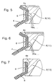
- FIGS. 5 to 7 show special embodiments of the invention Schlauchrollbalg-clamping:
- the groove base 14 has elevations 18a, 18b,..., which are arranged circumferentially on the cylindrical groove surface.
- Fig. 6 are in the groove base 14 circumferential recesses 20a, 20b, ... provided.
- Fig. 7 shows a "one-sided" entrapment of a hose bellows end 4a and 4b.
- D. h . The inventively provided groove flank bevel is formed only on a single groove flank 16 a, while the other groove flank 16 b is rectangular and does not contribute to the clamping of the hose rolling bellows end 4 a and 4 b.
Landscapes
- Engineering & Computer Science (AREA)
- General Engineering & Computer Science (AREA)
- Mechanical Engineering (AREA)
- Fluid-Damping Devices (AREA)
- Clamps And Clips (AREA)
- Rolls And Other Rotary Bodies (AREA)
Description
- Die Erfindung betrifft eine Rollbalg-Luftfeder und zwar insbesondere die Befestigung eines Schlauchrollbalges an einem endseitig am Balg jeweils formschlüssig zugfest und druckdicht anzubringenden Anschlussteil (Luftfederdeckel und/oder Abrollkolben).
- Die europäische Patentanmeldung
0 319 448 A2 beschäftigt sich mit der endseitigen Befestigung eines Luftfederbalges an jeweiligen Anschlussteilen. Die dortigeFig. 4 zeigt alle wesentlichen Details: Zur Befestigung eines Schlauchrollbalg-Endabschnittes weist das Befestigungsteil eine Nut auf. Diese Nut hat eine Grundfläche, die mit umlaufenden Rillen (24) versehen sein kann. Die Flanken der Nut sind teils gewölbt, teils unter verschiedenen Winkeln α und β konisch geneigt. Die Einspannung erfolgt durch Kompression des Balgs über die gesamte Höhe eines Spannringes. Da das Elastomermaterial des Balgs praktisch inkompressibel ist, hat die Einspannung über die gesamte Spannringhöhe hR zur Folge, dass in beträchtlichem Ausmaß Elastomermaterial zu beiden Seiten des Spannringes in Balg-Längsrichtung herausgequetscht wird. In Anbetracht der Tatsache, dass der Balg mit einem - gegenüber dem Gummi - gering dehnbaren Festigkeitsträger versehen ist, besteht die Befürchtung, dass die beträchtliche Längsverschiebung des Elastomermaterials zu unerwünscht überhöhten Längsspannungen innerhalb des Balgs und damit zu einer möglichen Ablösung des Elastomermaterials von dem nur gering dehnbaren Festigkeitsträger führen könnte. - Um im Einspannbereich des Balgs derartige interne Längsspannungen zu vermeiden, schlägt die
DE 41 42 561 A1 vor, den Endabschnitt des Balgs nicht über die gesamte Höhe des Spannringes einzupressen sondern lediglich an einem oberen und/oder unteren "Engpass" im Bereich mindestens einer der Flanken der Befestigungsnut. DieFig. 4 zeigt an der unteren Nutflanke (22) den "Engpass" (21), während der Balg über die gesamte Einspannhöhe des Spannringes praktisch nicht komprimiert ist. Wegen des rechteckigen Nutquerschnitts bei dieser inFig. 4 dargestellten Konstruktion erscheint das Einfügen des zu montierenden Spannringes nicht ohne weiteres möglich.
Eine leichtere Montagemöglichkeit lässt die inFig. 1 dargestellte Variante erwarten. Auch hier besteht die Grundidee der Balgbefestigung darin, dass über die Höhe der Einspannlänge keine Kompression und damit keine größere Materialverschiebung in Balg-Längsrichtung gegeben ist, sondern dass die Einspannung vielmehr lediglich an kurzen Engpässen (21) im Bereich der Nutflanken erfolgt. Die abgerundete Einspanngeometrie weist keine "Griffigkeit" auf. Damit scheint bei dieser inFig. 1 dargestellten Konstruktion die gewünschte Auszugsfestigkeit, insbesondere in dem Ausmaß, wie sie bei Nutzfahrzeugen zu fordern ist, nicht erfüllt zu sein. - Die Aufgabe der vorliegenden Erfindung besteht deshalb in einer zuverlässigen Befestigung eines Schlauchrollbalges an einem Anschlussteil, wobei eine Längsverschiebung von Elastomermaterial gegenüber dem darin integrierten Festigkeitsträger weitgehend vermieden wird.
- Gemäß Anspruch 1 besteht die Lösung dieser Aufgabe insbesondere in einer einerseits wirkungsvolleren und andererseits montagefreundlicheren Gestaltung des mindestens einen Einspann-"Engpasses".
- Der plastisch verformbare Spannring wird radial gestaucht. Aufgrund der konischen Ausbildung der Nutflanken ergibt sich eine selbstjustierende Einspannung des jeweils zwischen Nut und Spannring befindlichen Schlauchrollbalg-Endbereichs. Der zwischen der Spannringinnenfläche und dem Nutgrund befindliche Abschnitt des Schlauchrollbalg-Endbereichs ist dort nur knapp geklemmt, d.h. nur minimal gestaucht, um den Betrag, den die Inkompressibilität der Balgwand zulässt.
- Dabei wird der Schlauchrollbalg über die gesamte Spannring-Höhe, die etwa der Höhe des Nut-Grundes entspricht, praktisch nicht gestaucht, was zur Folge hat, dass kein Material in Schlauchrollbalg-Längsrichtung verschoben wird. Eine Trennung von dem in das Elastomermaterial des Balgs integrierten Festigkeitsträger ist deshalb nicht zu befürchten. Eine Einspannung ist lediglich "punktuell" gegeben, nämlich an einem oberen und einem unteren "Engpass". Die hier realisierte Einspannung ist deshalb so wirkungsvoll, weil sich eine geradlinige Fläche (Nutflanke) und eine keilförmige Kante (des Spannringes) als "Einspannbacken" gegenüberstehen. Wegen der Kürze des Engpasses gibt es keine nennenswerte Längsverschiebung von Elastomermaterial. Deshalb ist auch hier ein Ablösen des Elastomermaterials von dem in den Schlauchrollbalg integrierten Festigkeitsträger nicht zu befürchten.
Bei nicht so hoch beanspruchten Klemmungen kann eine einseitige Tiefbettkontur (Fig. 7 ) ausreichen, um den Balg zu halten. - Aufgrund der geometrischen Verhältnisse (Nutgrundhöhe≃ Spannringhöhe und Öffnungswinkel α zwischen Lot und Flankenrichtung α = 25° bis 35° (bei einfach konischer Flanke) bzw. 2α = 50° bis 70° (falls beide Flanken konisch geneigt sind) ergibt sich, dass der Balg im Einspannpunkt auf ca 45% bis 65% seiner Stärke komprimiert wird.
- Um höheren Dichtigkeitsanforderungen zu genügen und um eine weitere Erhöhung der Ausreißfestigkeit zu erreichen, kann es sinnvoll sein, den Tiefbettgrund mit einer zirkularen Profilierung (Vielzahnoberfläche,
Fig. 5 , oder einer Nutoberfläche,Fig. 6 ) zu versehen. Damit ergibt sich eine insgesamt höher belastbare Luftfedereinspannung. - Sind die Innenkanten des Spannringes leicht abgerundet oder sind die Innenkanten mit einer Fase versehen, so wird ein Durchtrennen des Balgs im Einspannpunkt zuverlässig vermieden.
- Die erfindungsgemäße Ausbildung der Tiefbettklemmung eignet sich auch problemlos für sogenannte "gekrempelte" Schlauchrollbälge bzw. Schlauchrollbalg-Enden.
- Da die erfindungsgemäße Tiefbettklemmung von Schlauchrollbälgen stark belastbar und äußerst zuverlässig ist, kann sie bevorzugt für Nutzfahrzeuge (Lkw und Busse) zum Einsatz gelangen.
Insgesamt stellen Schlauchrollbalgluftfedern mit der erfindungsgemäßen Tiefbettklemmung eine kostengünstigere Alternative zu Rollbalg-Luftfedern mit ringverstärkten Wülsten auf konischen Dichtflächen der Befestigungsteile dar. - Die wesentlichen Merkmale der erfindungsgemäßen Idee werden anhand der beigefügten Abbildungen erläutert. Es zeigt:
-
Fig. 1 den Längsschnitt (Axialschnitt) durch eine Schlauchrollbalg-Luftfeder mit erfindungsgemäß befestigten Rollbalg-Enden; -
Fig. 2 ebenfalls den Längsschnitt durch eine Schlauchrollbalg-Luftfeder, wobei das kolbenseitige Rollbalg-Ende vor der Montage gekrempelt wurde; -
Fig. 3 den sich auf die Befestigungs-Nut beziehenden Ausschnitt des Anschlussteils (im Längsschnitt); -
Fig. 4 den Ausschnitt: Anschlussteil/Rollbalg-Ende/Spannring (ebenfalls im Längsschnitt); und -
Fig. 5 bis 7 verschiedene Ausbildungen der erfindungsgemäßen Nut. - Die in den
Figuren 1 und2 dargestellten Luftfedern 2 bestehen im Wesentlichen aus einem Schlauchrollbalg 4, dessen Endabschnitte 4a, 4b formschlüssig, zugfest und druckdicht an jeweils einem Anschlussteil 8,10 angebracht sind. Das "obere" Anschlussteil 8 ist jeweils ein Luftfederdeckel, während das "untere" Anschlussteil 10 jeweils ein Abrollkolben ist. Zur Befestigung der Schlauchrollbalg-Enden 4a, 4b weisen die Anschlussteile 8, 10 jeweils eine speziell geformte Nut 12 auf. In diese Nuten 12 wird jeweils ein Endabschnitt 4a bzw. 4b eines Schlauchrollbalges 4 gegeben und jeweils mit Hilfe eines Spannringes 6 verklemmt. Durch plastisches Verformen des Spannringes 6 wird der Schlauchrollbalg 4 in die im jeweiligen Anschlussteil 8 und/oder 10 umlaufende, als "Tiefbettkontur" ausgebildete Nut 12 gedrückt. - Von der in
Fig. 1 dargestellten Luftfeder 2 unterscheidet sich die Luftfeder 2 gemäßFig. 2 in der Weise, dass hier der Schlauchrollbalg 4 zwecks Befestigung am Abrollkolben 10 zunächst "gekrempelt" worden ist. Hierdurch kommt die Außenseite des diesbezüglichen Schlauchrollbalg-Endes 4b an der Berührungsfläche der Nut 12 des Abrollkolbens 10 zu liegen, während die Innenseite des Schlauchrollbalg-Endes 4b an der Innenseite des Spannringes 6 anliegt. - Der Vorteil der Befestigung eines zuvor "gekrempelten" Schlauchrollbalges 4 bzw. Schlauchrollbalg-Endes 4a bzw. 4b besteht darin, dass ein Einfedern auch im völlig drucklosen Zustand der Luftfeder 2 problemlos möglich ist. Ein Einknicken und damit Beschädigen des Schlauchrollbalges 4 wird zuverlässig vermieden.
- Nähere Einzelheiten der sich im Anschlussteil 8, 10 (Deckel 8 und/oder Abrollkolben 10) befindlichen Nut 12 zeigt die
Fig. 3 . Die Nut 12 weist einen kegelstumpfförmigen Querschnitt auf mit einem geradlinigen Grund 14 der Höhe HN und geradlinig abgeschrägten Seitenflanken 16a, 16b. Die beiden Seitenflanken 16a, 16b sind gegenüber dem Lot L jeweils um den Winkel α geneigt, so dass die Nut 12 an ihrer Öffnung breiter ist als an ihrem Grund 14. Die Tiefe der Nut 12 ist mit "T" bezeichnet. - Wie aus
Fig. 4 ersichtlich, ist die Tiefe T der Nut 12 größer als die Stärke S des Schlauchrollbalges 4. Auf diese Weise kommt die Innenseite des Spannringes 6 unterhalb der Oberkanten der Nut-Flanken 16a, 16b zu liegen. Der Abstand vom Tiefbettgrund 14 zum Spannring 6 entspricht dabei ca. der Wandstärke S des Schlauchrollbalges 4.
Um Beschädigungen der Balgwand zu vermeiden, ist der Spannring 6 an seinen umlaufenden Kanten mit Fasen (0,5 x 45°) versehen. Um ein Abziehen des Spannringes 6 zu vermeiden, sollte die Tiefe der Nut 12 ca. Balgwandstärke +½ Spannringbreite B sein. Durch Einpresstiefe und Höhe des Spannringes 6 sowie Variation des Flankenwinkels α der Tiefbettkontur 12 kann die Verringerung der Balgwandstärke S im Bereich der Spannringkante variiert werden. Je nach Aufbau der Balgwand und Anforderung an die Klemmung kann die optimale Balgwandstärken-Reduzierung bei 30% bis 75% Balgwandstärke S liegen. - Darüber hinaus ist aus der
Fig. 4 zu entnehmen, dass die Spannring-Höhe HS ungefähr der Höhe HN des Nut-Grundes 14 entspricht. - Aus den dargestellten geometrischen Verhältnissen ergibt sich, dass die erfindungsgemäße Einspannung zwei "Engpässe" aufweist, nämlich jeweils einen zwischen der oberen und der unteren inneren Kante des Spannringes 6 einerseits und der jeweiligen Flanke 16a bzw. 16b der Nut 12 andererseits. Dabei ergibt sich eine punktuelle Kompression des Balgs 4 auf ca. 50% seiner Stärke S.
(Eine zweifach "punktuelle" Kompression ergibt sich lediglich in der Schnittbild-Darstellung. Tatsächlich erfolgt eine zweifach zirkulare Kompression entlang der inneren Ober- und der inneren Unterkante des kreisringförmigen Spannringes 6.) - Die
Figuren 5 bis 7 zeigen spezielle Ausführungsformen der erfindungsgemäßen Schlauchrollbalg-Einspannung:
GemäßFig. 5 weist der Nutgrund 14 Erhöhungen 18a, 18b, ... auf, die auf der zylindrischen Nutfläche umlaufend angeordnet sind.
GemäßFig. 6 sind im Nutgrund 14 umlaufende Vertiefungen 20a, 20b, ... vorgesehen.Fig. 7 zeigt eine "einseitige" Einklemmung eines Schlauchrollbalg-Endes 4a bzw. 4b. D. h.: Die erfindungsgemäß vorgesehene Nutflanken-Abschrägung ist lediglich an einer einzigen Nut-Flanke 16a ausgebildet, während die andere Nutflanke 16b rechtwinklig ist und nicht zur Einspannung des Schlauchrollbalg-Endes 4a bzw. 4b beiträgt. -
- 2
- Schlauchrollbalg-Luftfeder
- 4
- Schlauchrollbalg
- 4a, 4b
- Endabschnitt(e), Endbereich(e) des Schlauchrollbalgs
- 6
- Spannring
- 6a
- Innenseite des Rollbalgs 4
- 8,10
- Anschlussteil(e)
- 8
- Luftfederdeckel
- 10
- Abrollkolben
- 12
- Befestigungsnut im Anschlussteil 8 und/oder 10, Nut, "Tiefbettkontur"
- 14
- Grund, Tiefbettgrund, Boden der Nut
- 16a, 16b
- Flanke(n) der Nut
- α
- Öffnungswinkel einer Flanke
- L
- Lot
- HN
- Höhe der Nut
- T
- Tiefe der Nut
- HS
- Höhe des Spannringes
- B
- Spannringbreite
- S
- Stärke des Schlauchrollbalges
- 17
- Nutoberkante
- 18a, 18b, ...
- Erhöhungen im Grund der Nut
- 20a, 20b, ...
- Vertiefungen im Grund der Nut
- 22a, 22b
- Innenkanten des Spannringes
Claims (5)
- Schlauchrollbalg-Luftfeder (2),
wobei mindestens ein Endabschnitt (4a, 4b) des Schlauchrollbalgs (4) mittels eines Spannringes (6) an einem Anschlussteil (8, 10) formschlüssig zugfest und druckdicht befestigt ist, und
wobei das Anschlussteil (8, 10) eine Befestigungsnut (12) mit folgenden Merkmalen aufweist:(a) die Nut (12) hat einen kegelstumpfförmigen Querschnitt,(b) wobei der Grund (14) der Nut (12) zylindrisch, und(c) mindestens eine der Flanken (16a, 16b) der Nut (12) geradlinig konisch mit einem Öffnungswinkel (α) ausgebildet ist,(d) relativ zur Höhe (HS) des Spannringes (6) ist die Höhe (HN) der Grundfläche (14) der Nut (12) im Bereich von -15% bis +15%, d. h. 0,85≤ HN/HS≤ 1,15,(e) die Innenfläche (6a) des Spannringes (6) verläuft parallel zur Grundfläche (14) der im Anschlussteil (8, 10) befindlichen Nut (12),(f) im eingespannten Zustand ist der Innenradius des Spannringes (6) kleiner/gleich mindestens einer der Radien der Nut-Oberkanten (17),(g) der Abstand zwischen Grundfläche (14) der Nut (12) und Innenseite des Spannringes (6) entspricht im Wesentlichen der Wandstärke S des Schlauchrollbalges (4) reduziert um einen geringfügigen Betrag zur leichten Klemmung der Balgwand (4a, 4b),(h) der Spannring (6) bildet mit mindestens einer Nutflanke (16a und/oder 16b) einen die Balgwand des Endabschnittes (4a und/oder 4b) festklemmenden Engpass. - Schlauchrollbalg-Luftfeder nach Anspruch 1,
dadurch gekennzeichnet,
dass der Winkel (α) zwischen Luftfederradius und Richtung mindestens einer der Nut-Flanken (16a und/oder 16b) 25° bis 35° beträgt (25°≤ α≤ 35°). - Schlauchrollbalg-Luftfeder nach Anspruch 1 oder 2,
dadurch gekennzeichnet,
dass der Grund (14) der Nut (12) konzentrische Erhöhungen (18a, 18b, ...) oder Vertiefungen (20a, 20b, ...) aufweist. - Schlauchrollbalg-Luftfeder nach einem der Ansprüche 1 bis 3,
dadurch gekennzeichnet,
dass die Innenkanten (22a, 22b) des Spannringes (6) abgerundet sind und/oder mit einer Fase versehen sind. - Schlauchrollbalg-Luftfeder nach einem der Ansprüche 1 bis 4,
dadurch gekennzeichnet,
dass der Schlauchrollbalg (4) vor der Montage gekrempelt ist,
sodass im montierten Zustand seine Außenseite in Kontakt mit dem Grund (14) der Nut (12) steht, während seine Innenseite (6a) die Innenseite des Spannringes (6) berührt.
Applications Claiming Priority (2)
| Application Number | Priority Date | Filing Date | Title |
|---|---|---|---|
| DE102004056517A DE102004056517A1 (de) | 2004-11-24 | 2004-11-24 | Tiefbettklemmkontur für Schlauchrollbalg-Luftfedern |
| PCT/EP2005/010789 WO2006056267A1 (de) | 2004-11-24 | 2005-10-07 | Tiefbett-klemmkontur für schlauchrollbalg-luftfedern |
Publications (2)
| Publication Number | Publication Date |
|---|---|
| EP1817507A1 EP1817507A1 (de) | 2007-08-15 |
| EP1817507B1 true EP1817507B1 (de) | 2008-09-03 |
Family
ID=35229669
Family Applications (1)
| Application Number | Title | Priority Date | Filing Date |
|---|---|---|---|
| EP05795926A Revoked EP1817507B1 (de) | 2004-11-24 | 2005-10-07 | Tiefbett-klemmkontur für schlauchrollbalg-luftfedern |
Country Status (7)
| Country | Link |
|---|---|
| US (1) | US8220785B2 (de) |
| EP (1) | EP1817507B1 (de) |
| CN (1) | CN100549452C (de) |
| AT (1) | ATE407304T1 (de) |
| BR (1) | BRPI0512034A (de) |
| DE (2) | DE102004056517A1 (de) |
| WO (1) | WO2006056267A1 (de) |
Cited By (1)
| Publication number | Priority date | Publication date | Assignee | Title |
|---|---|---|---|---|
| EP2696095A1 (de) | 2012-08-07 | 2014-02-12 | Carl Freudenberg KG | Luftfeder mit Anschlüssen zur Befestigung der Enden eines Rollbalgs |
Families Citing this family (13)
| Publication number | Priority date | Publication date | Assignee | Title |
|---|---|---|---|---|
| DE10216750A1 (de) * | 2002-04-16 | 2003-10-30 | Contitech Luftfedersyst Gmbh | Schlauchrollbalg-Luftfeder |
| DE102005031477A1 (de) * | 2005-07-04 | 2007-01-11 | Continental Aktiengesellschaft | Luftfeder für Fahrzeuge |
| DE102006037664B4 (de) * | 2006-08-11 | 2022-01-05 | Continental Teves Ag & Co. Ohg | Verfahren zur Klemmung eines Schlauchrollbalgs einer Luftfeder |
| DE102007055077A1 (de) | 2007-11-16 | 2009-05-20 | Continental Aktiengesellschaft | Klemmkontur für ein druckbeaufschlagbares Bauteil und Spannmittel dafür |
| DE102009003822B4 (de) | 2009-04-24 | 2016-09-01 | Continental Teves Ag & Co. Ohg | Druckbeaufschlagbarer Bauteilverbund und Schlauchrollbalg-Luftfeder |
| DE102009052923A1 (de) * | 2009-11-12 | 2011-05-19 | Trw Automotive Gmbh | Kugelgelenk sowie Verfahren zum Befestigen eines Dichtungsbalgs an einem Kugelgelenk |
| US20120098173A1 (en) * | 2010-10-26 | 2012-04-26 | Vibracoustics North America, L.P. | Rebound Control Enhancement For Air Springs |
| US8733743B2 (en) * | 2010-12-23 | 2014-05-27 | Firestone Industrial Products Company, Llc | Gas spring piston, gas spring assembly and method |
| JP5912898B2 (ja) * | 2012-06-18 | 2016-04-27 | 川崎重工業株式会社 | 鉄道車両用台車 |
| JP5939065B2 (ja) * | 2012-07-19 | 2016-06-22 | 住友電気工業株式会社 | 空気ばね |
| US9387865B2 (en) * | 2013-02-18 | 2016-07-12 | Firestone Industrial Products Company, Llc | End member assemblies as well as gas spring assemblies and methods of manufacture including same |
| DE102016100939B4 (de) * | 2016-01-20 | 2023-08-10 | Vibracoustic Cv Air Springs Gmbh | Luftfeder |
| CN107906152A (zh) * | 2017-11-28 | 2018-04-13 | 东风商用车有限公司 | 一种小体积低刚度气囊弹簧 |
Family Cites Families (11)
| Publication number | Priority date | Publication date | Assignee | Title |
|---|---|---|---|---|
| JPS6044630A (ja) * | 1983-08-23 | 1985-03-09 | Sumitomo Electric Ind Ltd | 空気ばね |
| DE3346108A1 (de) * | 1983-12-21 | 1985-07-04 | Continental Gummi Werke Ag | Luftfederung insbesondere fuer strassenfahrzeuge |
| US4793598A (en) * | 1986-09-24 | 1988-12-27 | The Firestone Tire & Rubber Company | Air spring having internal sealing band and method of installing same |
| DE3643073A1 (de) * | 1986-12-17 | 1988-06-30 | Phoenix Ag | Luftfeder |
| US5005808A (en) * | 1987-12-01 | 1991-04-09 | The Goodyear Tire & Rubber Company | Airspring end member and airspring assembly |
| DE4142561C2 (de) * | 1991-12-21 | 1995-04-27 | Continental Ag | Luftfeder mit einem wulstlosen Luftfederbalg aus elastomerem Werkstoff |
| US5382006A (en) * | 1993-09-29 | 1995-01-17 | The Goodyear Tire & Rubber Company | Airspring piston and airspring assembly |
| DE4423601C2 (de) * | 1994-07-06 | 1997-08-21 | Continental Ag | Luftfederrollbalg aus elastomerem Werkstoff |
| CN2311654Y (zh) * | 1996-12-04 | 1999-03-24 | 铁道部四方车辆研究所 | 弹性支承可调阻尼式空气弹簧 |
| US6036180A (en) * | 1998-02-26 | 2000-03-14 | Bridgestone/Firestone, Inc. | Tear-drop shaped clamp assembly and tapered end cap for an air spring |
| ATE435380T1 (de) | 2003-04-03 | 2009-07-15 | Freudenberg Carl Kg | Luftfederanordnung |
-
2004
- 2004-11-24 DE DE102004056517A patent/DE102004056517A1/de not_active Withdrawn
-
2005
- 2005-10-07 BR BRPI0512034-9A patent/BRPI0512034A/pt not_active IP Right Cessation
- 2005-10-07 WO PCT/EP2005/010789 patent/WO2006056267A1/de active IP Right Grant
- 2005-10-07 AT AT05795926T patent/ATE407304T1/de not_active IP Right Cessation
- 2005-10-07 US US11/791,211 patent/US8220785B2/en active Active
- 2005-10-07 CN CNB2005800403463A patent/CN100549452C/zh not_active Expired - Fee Related
- 2005-10-07 EP EP05795926A patent/EP1817507B1/de not_active Revoked
- 2005-10-07 DE DE502005005289T patent/DE502005005289D1/de active Active
Cited By (2)
| Publication number | Priority date | Publication date | Assignee | Title |
|---|---|---|---|---|
| EP2696095A1 (de) | 2012-08-07 | 2014-02-12 | Carl Freudenberg KG | Luftfeder mit Anschlüssen zur Befestigung der Enden eines Rollbalgs |
| WO2014023461A1 (de) | 2012-08-07 | 2014-02-13 | Carl Freudenberg Kg | Luftfeder mit anschlüssen zur befestigung der enden eines rollbalgs |
Also Published As
| Publication number | Publication date |
|---|---|
| US20080290570A1 (en) | 2008-11-27 |
| DE102004056517A1 (de) | 2006-06-01 |
| US8220785B2 (en) | 2012-07-17 |
| DE502005005289D1 (de) | 2008-10-16 |
| EP1817507A1 (de) | 2007-08-15 |
| WO2006056267A1 (de) | 2006-06-01 |
| BRPI0512034A (pt) | 2008-02-06 |
| CN101065601A (zh) | 2007-10-31 |
| CN100549452C (zh) | 2009-10-14 |
| ATE407304T1 (de) | 2008-09-15 |
Similar Documents
| Publication | Publication Date | Title |
|---|---|---|
| EP1817507B1 (de) | Tiefbett-klemmkontur für schlauchrollbalg-luftfedern | |
| EP0520164B1 (de) | Schraubenverbindung | |
| DE102006021011B4 (de) | Buchsenlager mit axialseitig profiliertem Lagerkörper | |
| EP1233205A2 (de) | Federungsanordnung | |
| EP1778988B1 (de) | Kugelgelenk | |
| DE112008004188T5 (de) | Grommet | |
| EP1270987A2 (de) | Aggregatelager in Buchsenform | |
| EP0493731B1 (de) | Elastisches Lager | |
| EP0863334B1 (de) | Faltenbalg | |
| WO1998005520A1 (de) | Pendelstütze und verfahren zu deren herstellung | |
| EP0990811B1 (de) | Vormontierte balgartige Anordnung zum Ummanteln von Gelenkwellen | |
| DE4325576C2 (de) | Luftfeder für Fahrzeuge mit einem elastomeren, kernlosen Schlauchrollbalg | |
| EP0548581B1 (de) | Luftfeder mit einem wulstlosen Luftfederbalg aus elastomerem Werkstoff | |
| EP1128085A2 (de) | Federunterlage | |
| EP0734888A1 (de) | Oberes Federbeinstützlager für Radaufhängungen in einem Kraftfahrzeug | |
| DE10338065B4 (de) | Sicherheitsvorrichtung | |
| DE10247757B3 (de) | Drehmomentstütze, insbesondere zum Abstützen des Motors an der Karosserie eines Kraftfahrzeugs | |
| WO1999016648A1 (de) | Wischeranlage | |
| DE10213064A1 (de) | Elastomere Dichtung | |
| DE3030878A1 (de) | Kupplungsausruecklager | |
| DE4136598C2 (de) | Gummi-Metall-Federelement | |
| DE3824854A1 (de) | Verbindungselement fuer langgestreckte teile | |
| DE19928599C5 (de) | Elastisches Lager zum Abstützen eines Bauteils | |
| DE3610283A1 (de) | Gelenkverbindung | |
| DE19723739C2 (de) | Radführung für ein Kraftfahrzeug |
Legal Events
| Date | Code | Title | Description |
|---|---|---|---|
| PUAI | Public reference made under article 153(3) epc to a published international application that has entered the european phase |
Free format text: ORIGINAL CODE: 0009012 |
|
| 17P | Request for examination filed |
Effective date: 20070625 |
|
| AK | Designated contracting states |
Kind code of ref document: A1 Designated state(s): AT BE BG CH CY CZ DE DK EE ES FI FR GB GR HU IE IS IT LI LT LU LV MC NL PL PT RO SE SI SK TR |
|
| DAX | Request for extension of the european patent (deleted) | ||
| GRAP | Despatch of communication of intention to grant a patent |
Free format text: ORIGINAL CODE: EPIDOSNIGR1 |
|
| GRAS | Grant fee paid |
Free format text: ORIGINAL CODE: EPIDOSNIGR3 |
|
| GRAA | (expected) grant |
Free format text: ORIGINAL CODE: 0009210 |
|
| RTI1 | Title (correction) |
Free format text: DROP BASE RING CLAMPING CONTOUR FOR ROLLING-BELLOWS-TYPE PNEUMATIC SPRINGS |
|
| AK | Designated contracting states |
Kind code of ref document: B1 Designated state(s): AT BE BG CH CY CZ DE DK EE ES FI FR GB GR HU IE IS IT LI LT LU LV MC NL PL PT RO SE SI SK TR |
|
| REG | Reference to a national code |
Ref country code: GB Ref legal event code: FG4D Free format text: NOT ENGLISH |
|
| REG | Reference to a national code |
Ref country code: CH Ref legal event code: EP |
|
| REG | Reference to a national code |
Ref country code: IE Ref legal event code: FG4D Free format text: LANGUAGE OF EP DOCUMENT: GERMAN |
|
| REF | Corresponds to: |
Ref document number: 502005005289 Country of ref document: DE Date of ref document: 20081016 Kind code of ref document: P |
|
| REG | Reference to a national code |
Ref country code: SE Ref legal event code: TRGR |
|
| PG25 | Lapsed in a contracting state [announced via postgrant information from national office to epo] |
Ref country code: NL Free format text: LAPSE BECAUSE OF FAILURE TO SUBMIT A TRANSLATION OF THE DESCRIPTION OR TO PAY THE FEE WITHIN THE PRESCRIBED TIME-LIMIT Effective date: 20080903 Ref country code: LT Free format text: LAPSE BECAUSE OF FAILURE TO SUBMIT A TRANSLATION OF THE DESCRIPTION OR TO PAY THE FEE WITHIN THE PRESCRIBED TIME-LIMIT Effective date: 20080903 |
|
| PG25 | Lapsed in a contracting state [announced via postgrant information from national office to epo] |
Ref country code: ES Free format text: LAPSE BECAUSE OF FAILURE TO SUBMIT A TRANSLATION OF THE DESCRIPTION OR TO PAY THE FEE WITHIN THE PRESCRIBED TIME-LIMIT Effective date: 20081214 Ref country code: FI Free format text: LAPSE BECAUSE OF FAILURE TO SUBMIT A TRANSLATION OF THE DESCRIPTION OR TO PAY THE FEE WITHIN THE PRESCRIBED TIME-LIMIT Effective date: 20080903 Ref country code: SI Free format text: LAPSE BECAUSE OF FAILURE TO SUBMIT A TRANSLATION OF THE DESCRIPTION OR TO PAY THE FEE WITHIN THE PRESCRIBED TIME-LIMIT Effective date: 20080903 Ref country code: LV Free format text: LAPSE BECAUSE OF FAILURE TO SUBMIT A TRANSLATION OF THE DESCRIPTION OR TO PAY THE FEE WITHIN THE PRESCRIBED TIME-LIMIT Effective date: 20080903 |
|
| NLV1 | Nl: lapsed or annulled due to failure to fulfill the requirements of art. 29p and 29m of the patents act | ||
| REG | Reference to a national code |
Ref country code: IE Ref legal event code: FD4D |
|
| BERE | Be: lapsed |
Owner name: CONTITECH LUFTFEDERSYSTEME G.M.B.H. Effective date: 20081031 |
|
| PG25 | Lapsed in a contracting state [announced via postgrant information from national office to epo] |
Ref country code: BG Free format text: LAPSE BECAUSE OF FAILURE TO SUBMIT A TRANSLATION OF THE DESCRIPTION OR TO PAY THE FEE WITHIN THE PRESCRIBED TIME-LIMIT Effective date: 20081203 Ref country code: IE Free format text: LAPSE BECAUSE OF FAILURE TO SUBMIT A TRANSLATION OF THE DESCRIPTION OR TO PAY THE FEE WITHIN THE PRESCRIBED TIME-LIMIT Effective date: 20080903 |
|
| PG25 | Lapsed in a contracting state [announced via postgrant information from national office to epo] |
Ref country code: SK Free format text: LAPSE BECAUSE OF FAILURE TO SUBMIT A TRANSLATION OF THE DESCRIPTION OR TO PAY THE FEE WITHIN THE PRESCRIBED TIME-LIMIT Effective date: 20080903 Ref country code: RO Free format text: LAPSE BECAUSE OF FAILURE TO SUBMIT A TRANSLATION OF THE DESCRIPTION OR TO PAY THE FEE WITHIN THE PRESCRIBED TIME-LIMIT Effective date: 20080903 Ref country code: PT Free format text: LAPSE BECAUSE OF FAILURE TO SUBMIT A TRANSLATION OF THE DESCRIPTION OR TO PAY THE FEE WITHIN THE PRESCRIBED TIME-LIMIT Effective date: 20090203 Ref country code: CZ Free format text: LAPSE BECAUSE OF FAILURE TO SUBMIT A TRANSLATION OF THE DESCRIPTION OR TO PAY THE FEE WITHIN THE PRESCRIBED TIME-LIMIT Effective date: 20080903 Ref country code: IS Free format text: LAPSE BECAUSE OF FAILURE TO SUBMIT A TRANSLATION OF THE DESCRIPTION OR TO PAY THE FEE WITHIN THE PRESCRIBED TIME-LIMIT Effective date: 20090103 Ref country code: MC Free format text: LAPSE BECAUSE OF NON-PAYMENT OF DUE FEES Effective date: 20081031 |
|
| PLBI | Opposition filed |
Free format text: ORIGINAL CODE: 0009260 |
|
| 26 | Opposition filed |
Opponent name: CARL FREUDENBERG KG Effective date: 20090528 |
|
| PLAX | Notice of opposition and request to file observation + time limit sent |
Free format text: ORIGINAL CODE: EPIDOSNOBS2 |
|
| PG25 | Lapsed in a contracting state [announced via postgrant information from national office to epo] |
Ref country code: EE Free format text: LAPSE BECAUSE OF FAILURE TO SUBMIT A TRANSLATION OF THE DESCRIPTION OR TO PAY THE FEE WITHIN THE PRESCRIBED TIME-LIMIT Effective date: 20080903 Ref country code: DK Free format text: LAPSE BECAUSE OF FAILURE TO SUBMIT A TRANSLATION OF THE DESCRIPTION OR TO PAY THE FEE WITHIN THE PRESCRIBED TIME-LIMIT Effective date: 20080903 |
|
| PG25 | Lapsed in a contracting state [announced via postgrant information from national office to epo] |
Ref country code: IT Free format text: LAPSE BECAUSE OF FAILURE TO SUBMIT A TRANSLATION OF THE DESCRIPTION OR TO PAY THE FEE WITHIN THE PRESCRIBED TIME-LIMIT Effective date: 20080903 |
|
| PG25 | Lapsed in a contracting state [announced via postgrant information from national office to epo] |
Ref country code: BE Free format text: LAPSE BECAUSE OF NON-PAYMENT OF DUE FEES Effective date: 20081031 |
|
| PLBB | Reply of patent proprietor to notice(s) of opposition received |
Free format text: ORIGINAL CODE: EPIDOSNOBS3 |
|
| PG25 | Lapsed in a contracting state [announced via postgrant information from national office to epo] |
Ref country code: AT Free format text: LAPSE BECAUSE OF NON-PAYMENT OF DUE FEES Effective date: 20081007 |
|
| PG25 | Lapsed in a contracting state [announced via postgrant information from national office to epo] |
Ref country code: PL Free format text: LAPSE BECAUSE OF FAILURE TO SUBMIT A TRANSLATION OF THE DESCRIPTION OR TO PAY THE FEE WITHIN THE PRESCRIBED TIME-LIMIT Effective date: 20080903 |
|
| REG | Reference to a national code |
Ref country code: CH Ref legal event code: PL |
|
| PG25 | Lapsed in a contracting state [announced via postgrant information from national office to epo] |
Ref country code: LU Free format text: LAPSE BECAUSE OF NON-PAYMENT OF DUE FEES Effective date: 20081007 Ref country code: CY Free format text: LAPSE BECAUSE OF FAILURE TO SUBMIT A TRANSLATION OF THE DESCRIPTION OR TO PAY THE FEE WITHIN THE PRESCRIBED TIME-LIMIT Effective date: 20080903 |
|
| PG25 | Lapsed in a contracting state [announced via postgrant information from national office to epo] |
Ref country code: CH Free format text: LAPSE BECAUSE OF NON-PAYMENT OF DUE FEES Effective date: 20091031 Ref country code: LI Free format text: LAPSE BECAUSE OF NON-PAYMENT OF DUE FEES Effective date: 20091031 Ref country code: GR Free format text: LAPSE BECAUSE OF FAILURE TO SUBMIT A TRANSLATION OF THE DESCRIPTION OR TO PAY THE FEE WITHIN THE PRESCRIBED TIME-LIMIT Effective date: 20081204 |
|
| PG25 | Lapsed in a contracting state [announced via postgrant information from national office to epo] |
Ref country code: GB Free format text: LAPSE BECAUSE OF NON-PAYMENT OF DUE FEES Effective date: 20091007 |
|
| APBM | Appeal reference recorded |
Free format text: ORIGINAL CODE: EPIDOSNREFNO |
|
| APBP | Date of receipt of notice of appeal recorded |
Free format text: ORIGINAL CODE: EPIDOSNNOA2O |
|
| APAH | Appeal reference modified |
Free format text: ORIGINAL CODE: EPIDOSCREFNO |
|
| APBQ | Date of receipt of statement of grounds of appeal recorded |
Free format text: ORIGINAL CODE: EPIDOSNNOA3O |
|
| PGFP | Annual fee paid to national office [announced via postgrant information from national office to epo] |
Ref country code: TR Payment date: 20120928 Year of fee payment: 8 |
|
| PGFP | Annual fee paid to national office [announced via postgrant information from national office to epo] |
Ref country code: HU Payment date: 20121029 Year of fee payment: 8 Ref country code: DE Payment date: 20121031 Year of fee payment: 8 |
|
| REG | Reference to a national code |
Ref country code: DE Ref legal event code: R064 Ref document number: 502005005289 Country of ref document: DE Ref country code: DE Ref legal event code: R103 Ref document number: 502005005289 Country of ref document: DE |
|
| APBU | Appeal procedure closed |
Free format text: ORIGINAL CODE: EPIDOSNNOA9O |
|
| PLAB | Opposition data, opponent's data or that of the opponent's representative modified |
Free format text: ORIGINAL CODE: 0009299OPPO |
|
| APAN | Information on closure of appeal procedure modified |
Free format text: ORIGINAL CODE: EPIDOSCNOA9O |
|
| R26 | Opposition filed (corrected) |
Opponent name: CARL FREUDENBERG KG Effective date: 20090528 |
|
| APAN | Information on closure of appeal procedure modified |
Free format text: ORIGINAL CODE: EPIDOSCNOA9O |
|
| RDAF | Communication despatched that patent is revoked |
Free format text: ORIGINAL CODE: EPIDOSNREV1 |
|
| RDAG | Patent revoked |
Free format text: ORIGINAL CODE: 0009271 |
|
| STAA | Information on the status of an ep patent application or granted ep patent |
Free format text: STATUS: PATENT REVOKED |
|
| 27W | Patent revoked |
Effective date: 20130716 |
|
| REG | Reference to a national code |
Ref country code: DE Ref legal event code: R107 Ref document number: 502005005289 Country of ref document: DE Effective date: 20140123 |
|
| PGFP | Annual fee paid to national office [announced via postgrant information from national office to epo] |
Ref country code: FR Payment date: 20131022 Year of fee payment: 9 |
|
| REG | Reference to a national code |
Ref country code: AT Ref legal event code: MA03 Ref document number: 407304 Country of ref document: AT Kind code of ref document: T Effective date: 20130716 |
|
| REG | Reference to a national code |
Ref country code: SE Ref legal event code: ECNC |
|
| PGFP | Annual fee paid to national office [announced via postgrant information from national office to epo] |
Ref country code: SE Payment date: 20141021 Year of fee payment: 10 |