EP1815962B1 - Verfahren zum Formen eines Gegenstandes von mit Glasfasern verstärktem Harzmaterial - Google Patents
Verfahren zum Formen eines Gegenstandes von mit Glasfasern verstärktem Harzmaterial Download PDFInfo
- Publication number
- EP1815962B1 EP1815962B1 EP07001521A EP07001521A EP1815962B1 EP 1815962 B1 EP1815962 B1 EP 1815962B1 EP 07001521 A EP07001521 A EP 07001521A EP 07001521 A EP07001521 A EP 07001521A EP 1815962 B1 EP1815962 B1 EP 1815962B1
- Authority
- EP
- European Patent Office
- Prior art keywords
- fiber
- resin
- reinforcement
- foaming agent
- molded article
- Prior art date
- Legal status (The legal status is an assumption and is not a legal conclusion. Google has not performed a legal analysis and makes no representation as to the accuracy of the status listed.)
- Ceased
Links
Images


Classifications
-
- B—PERFORMING OPERATIONS; TRANSPORTING
- B29—WORKING OF PLASTICS; WORKING OF SUBSTANCES IN A PLASTIC STATE IN GENERAL
- B29C—SHAPING OR JOINING OF PLASTICS; SHAPING OF MATERIAL IN A PLASTIC STATE, NOT OTHERWISE PROVIDED FOR; AFTER-TREATMENT OF THE SHAPED PRODUCTS, e.g. REPAIRING
- B29C44/00—Shaping by internal pressure generated in the material, e.g. swelling or foaming ; Producing porous or cellular expanded plastics articles
- B29C44/02—Shaping by internal pressure generated in the material, e.g. swelling or foaming ; Producing porous or cellular expanded plastics articles for articles of definite length, i.e. discrete articles
- B29C44/12—Incorporating or moulding on preformed parts, e.g. inserts or reinforcements
-
- B—PERFORMING OPERATIONS; TRANSPORTING
- B29—WORKING OF PLASTICS; WORKING OF SUBSTANCES IN A PLASTIC STATE IN GENERAL
- B29B—PREPARATION OR PRETREATMENT OF THE MATERIAL TO BE SHAPED; MAKING GRANULES OR PREFORMS; RECOVERY OF PLASTICS OR OTHER CONSTITUENTS OF WASTE MATERIAL CONTAINING PLASTICS
- B29B7/00—Mixing; Kneading
- B29B7/30—Mixing; Kneading continuous, with mechanical mixing or kneading devices
- B29B7/32—Mixing; Kneading continuous, with mechanical mixing or kneading devices with non-movable mixing or kneading devices
- B29B7/325—Static mixers
-
- B—PERFORMING OPERATIONS; TRANSPORTING
- B29—WORKING OF PLASTICS; WORKING OF SUBSTANCES IN A PLASTIC STATE IN GENERAL
- B29B—PREPARATION OR PRETREATMENT OF THE MATERIAL TO BE SHAPED; MAKING GRANULES OR PREFORMS; RECOVERY OF PLASTICS OR OTHER CONSTITUENTS OF WASTE MATERIAL CONTAINING PLASTICS
- B29B7/00—Mixing; Kneading
- B29B7/30—Mixing; Kneading continuous, with mechanical mixing or kneading devices
- B29B7/58—Component parts, details or accessories; Auxiliary operations
- B29B7/60—Component parts, details or accessories; Auxiliary operations for feeding, e.g. end guides for the incoming material
-
- B—PERFORMING OPERATIONS; TRANSPORTING
- B29—WORKING OF PLASTICS; WORKING OF SUBSTANCES IN A PLASTIC STATE IN GENERAL
- B29B—PREPARATION OR PRETREATMENT OF THE MATERIAL TO BE SHAPED; MAKING GRANULES OR PREFORMS; RECOVERY OF PLASTICS OR OTHER CONSTITUENTS OF WASTE MATERIAL CONTAINING PLASTICS
- B29B7/00—Mixing; Kneading
- B29B7/80—Component parts, details or accessories; Auxiliary operations
- B29B7/88—Adding charges, i.e. additives
- B29B7/90—Fillers or reinforcements, e.g. fibres
-
- B—PERFORMING OPERATIONS; TRANSPORTING
- B29—WORKING OF PLASTICS; WORKING OF SUBSTANCES IN A PLASTIC STATE IN GENERAL
- B29C—SHAPING OR JOINING OF PLASTICS; SHAPING OF MATERIAL IN A PLASTIC STATE, NOT OTHERWISE PROVIDED FOR; AFTER-TREATMENT OF THE SHAPED PRODUCTS, e.g. REPAIRING
- B29C44/00—Shaping by internal pressure generated in the material, e.g. swelling or foaming ; Producing porous or cellular expanded plastics articles
- B29C44/34—Auxiliary operations
- B29C44/3442—Mixing, kneading or conveying the foamable material
-
- B—PERFORMING OPERATIONS; TRANSPORTING
- B29—WORKING OF PLASTICS; WORKING OF SUBSTANCES IN A PLASTIC STATE IN GENERAL
- B29C—SHAPING OR JOINING OF PLASTICS; SHAPING OF MATERIAL IN A PLASTIC STATE, NOT OTHERWISE PROVIDED FOR; AFTER-TREATMENT OF THE SHAPED PRODUCTS, e.g. REPAIRING
- B29C44/00—Shaping by internal pressure generated in the material, e.g. swelling or foaming ; Producing porous or cellular expanded plastics articles
- B29C44/34—Auxiliary operations
- B29C44/60—Measuring, controlling or regulating
-
- B—PERFORMING OPERATIONS; TRANSPORTING
- B29—WORKING OF PLASTICS; WORKING OF SUBSTANCES IN A PLASTIC STATE IN GENERAL
- B29C—SHAPING OR JOINING OF PLASTICS; SHAPING OF MATERIAL IN A PLASTIC STATE, NOT OTHERWISE PROVIDED FOR; AFTER-TREATMENT OF THE SHAPED PRODUCTS, e.g. REPAIRING
- B29C48/00—Extrusion moulding, i.e. expressing the moulding material through a die or nozzle which imparts the desired form; Apparatus therefor
- B29C48/022—Extrusion moulding, i.e. expressing the moulding material through a die or nozzle which imparts the desired form; Apparatus therefor characterised by the choice of material
-
- B—PERFORMING OPERATIONS; TRANSPORTING
- B29—WORKING OF PLASTICS; WORKING OF SUBSTANCES IN A PLASTIC STATE IN GENERAL
- B29C—SHAPING OR JOINING OF PLASTICS; SHAPING OF MATERIAL IN A PLASTIC STATE, NOT OTHERWISE PROVIDED FOR; AFTER-TREATMENT OF THE SHAPED PRODUCTS, e.g. REPAIRING
- B29C48/00—Extrusion moulding, i.e. expressing the moulding material through a die or nozzle which imparts the desired form; Apparatus therefor
- B29C48/25—Component parts, details or accessories; Auxiliary operations
- B29C48/255—Flow control means, e.g. valves
-
- B—PERFORMING OPERATIONS; TRANSPORTING
- B29—WORKING OF PLASTICS; WORKING OF SUBSTANCES IN A PLASTIC STATE IN GENERAL
- B29C—SHAPING OR JOINING OF PLASTICS; SHAPING OF MATERIAL IN A PLASTIC STATE, NOT OTHERWISE PROVIDED FOR; AFTER-TREATMENT OF THE SHAPED PRODUCTS, e.g. REPAIRING
- B29C48/00—Extrusion moulding, i.e. expressing the moulding material through a die or nozzle which imparts the desired form; Apparatus therefor
- B29C48/25—Component parts, details or accessories; Auxiliary operations
- B29C48/285—Feeding the extrusion material to the extruder
- B29C48/288—Feeding the extrusion material to the extruder in solid form, e.g. powder or granules
- B29C48/2886—Feeding the extrusion material to the extruder in solid form, e.g. powder or granules of fillers or of fibrous materials, e.g. short-fibre reinforcements
-
- B—PERFORMING OPERATIONS; TRANSPORTING
- B29—WORKING OF PLASTICS; WORKING OF SUBSTANCES IN A PLASTIC STATE IN GENERAL
- B29C—SHAPING OR JOINING OF PLASTICS; SHAPING OF MATERIAL IN A PLASTIC STATE, NOT OTHERWISE PROVIDED FOR; AFTER-TREATMENT OF THE SHAPED PRODUCTS, e.g. REPAIRING
- B29C45/00—Injection moulding, i.e. forcing the required volume of moulding material through a nozzle into a closed mould; Apparatus therefor
- B29C45/17—Component parts, details or accessories; Auxiliary operations
- B29C45/46—Means for plasticising or homogenising the moulding material or forcing it into the mould
- B29C2045/466—Means for plasticising or homogenising the moulding material or forcing it into the mould supplying the injection unit directly by a compounder
-
- B—PERFORMING OPERATIONS; TRANSPORTING
- B29—WORKING OF PLASTICS; WORKING OF SUBSTANCES IN A PLASTIC STATE IN GENERAL
- B29C—SHAPING OR JOINING OF PLASTICS; SHAPING OF MATERIAL IN A PLASTIC STATE, NOT OTHERWISE PROVIDED FOR; AFTER-TREATMENT OF THE SHAPED PRODUCTS, e.g. REPAIRING
- B29C45/00—Injection moulding, i.e. forcing the required volume of moulding material through a nozzle into a closed mould; Apparatus therefor
- B29C45/17—Component parts, details or accessories; Auxiliary operations
- B29C45/26—Moulds
- B29C45/27—Sprue channels ; Runner channels or runner nozzles
- B29C45/30—Flow control means disposed within the sprue channel, e.g. "torpedo" construction
-
- B—PERFORMING OPERATIONS; TRANSPORTING
- B29—WORKING OF PLASTICS; WORKING OF SUBSTANCES IN A PLASTIC STATE IN GENERAL
- B29C—SHAPING OR JOINING OF PLASTICS; SHAPING OF MATERIAL IN A PLASTIC STATE, NOT OTHERWISE PROVIDED FOR; AFTER-TREATMENT OF THE SHAPED PRODUCTS, e.g. REPAIRING
- B29C45/00—Injection moulding, i.e. forcing the required volume of moulding material through a nozzle into a closed mould; Apparatus therefor
- B29C45/17—Component parts, details or accessories; Auxiliary operations
- B29C45/46—Means for plasticising or homogenising the moulding material or forcing it into the mould
- B29C45/47—Means for plasticising or homogenising the moulding material or forcing it into the mould using screws
- B29C45/48—Plasticising screw and injection screw comprising two separate screws
-
- B—PERFORMING OPERATIONS; TRANSPORTING
- B29—WORKING OF PLASTICS; WORKING OF SUBSTANCES IN A PLASTIC STATE IN GENERAL
- B29C—SHAPING OR JOINING OF PLASTICS; SHAPING OF MATERIAL IN A PLASTIC STATE, NOT OTHERWISE PROVIDED FOR; AFTER-TREATMENT OF THE SHAPED PRODUCTS, e.g. REPAIRING
- B29C45/00—Injection moulding, i.e. forcing the required volume of moulding material through a nozzle into a closed mould; Apparatus therefor
- B29C45/17—Component parts, details or accessories; Auxiliary operations
- B29C45/46—Means for plasticising or homogenising the moulding material or forcing it into the mould
- B29C45/53—Means for plasticising or homogenising the moulding material or forcing it into the mould using injection ram or piston
- B29C45/54—Means for plasticising or homogenising the moulding material or forcing it into the mould using injection ram or piston and plasticising screw
-
- B—PERFORMING OPERATIONS; TRANSPORTING
- B29—WORKING OF PLASTICS; WORKING OF SUBSTANCES IN A PLASTIC STATE IN GENERAL
- B29C—SHAPING OR JOINING OF PLASTICS; SHAPING OF MATERIAL IN A PLASTIC STATE, NOT OTHERWISE PROVIDED FOR; AFTER-TREATMENT OF THE SHAPED PRODUCTS, e.g. REPAIRING
- B29C45/00—Injection moulding, i.e. forcing the required volume of moulding material through a nozzle into a closed mould; Apparatus therefor
- B29C45/17—Component parts, details or accessories; Auxiliary operations
- B29C45/46—Means for plasticising or homogenising the moulding material or forcing it into the mould
- B29C45/56—Means for plasticising or homogenising the moulding material or forcing it into the mould using mould parts movable during or after injection, e.g. injection-compression moulding
- B29C45/568—Applying vibrations to the mould parts
-
- B—PERFORMING OPERATIONS; TRANSPORTING
- B29—WORKING OF PLASTICS; WORKING OF SUBSTANCES IN A PLASTIC STATE IN GENERAL
- B29C—SHAPING OR JOINING OF PLASTICS; SHAPING OF MATERIAL IN A PLASTIC STATE, NOT OTHERWISE PROVIDED FOR; AFTER-TREATMENT OF THE SHAPED PRODUCTS, e.g. REPAIRING
- B29C45/00—Injection moulding, i.e. forcing the required volume of moulding material through a nozzle into a closed mould; Apparatus therefor
- B29C45/17—Component parts, details or accessories; Auxiliary operations
- B29C45/46—Means for plasticising or homogenising the moulding material or forcing it into the mould
- B29C45/58—Details
- B29C45/581—Devices for influencing the material flow, e.g. "torpedo constructions" or mixing devices
-
- B—PERFORMING OPERATIONS; TRANSPORTING
- B29—WORKING OF PLASTICS; WORKING OF SUBSTANCES IN A PLASTIC STATE IN GENERAL
- B29C—SHAPING OR JOINING OF PLASTICS; SHAPING OF MATERIAL IN A PLASTIC STATE, NOT OTHERWISE PROVIDED FOR; AFTER-TREATMENT OF THE SHAPED PRODUCTS, e.g. REPAIRING
- B29C48/00—Extrusion moulding, i.e. expressing the moulding material through a die or nozzle which imparts the desired form; Apparatus therefor
- B29C48/025—General arrangement or layout of plant
-
- B—PERFORMING OPERATIONS; TRANSPORTING
- B29—WORKING OF PLASTICS; WORKING OF SUBSTANCES IN A PLASTIC STATE IN GENERAL
- B29C—SHAPING OR JOINING OF PLASTICS; SHAPING OF MATERIAL IN A PLASTIC STATE, NOT OTHERWISE PROVIDED FOR; AFTER-TREATMENT OF THE SHAPED PRODUCTS, e.g. REPAIRING
- B29C48/00—Extrusion moulding, i.e. expressing the moulding material through a die or nozzle which imparts the desired form; Apparatus therefor
- B29C48/03—Extrusion moulding, i.e. expressing the moulding material through a die or nozzle which imparts the desired form; Apparatus therefor characterised by the shape of the extruded material at extrusion
-
- B—PERFORMING OPERATIONS; TRANSPORTING
- B29—WORKING OF PLASTICS; WORKING OF SUBSTANCES IN A PLASTIC STATE IN GENERAL
- B29C—SHAPING OR JOINING OF PLASTICS; SHAPING OF MATERIAL IN A PLASTIC STATE, NOT OTHERWISE PROVIDED FOR; AFTER-TREATMENT OF THE SHAPED PRODUCTS, e.g. REPAIRING
- B29C48/00—Extrusion moulding, i.e. expressing the moulding material through a die or nozzle which imparts the desired form; Apparatus therefor
- B29C48/14—Extrusion moulding, i.e. expressing the moulding material through a die or nozzle which imparts the desired form; Apparatus therefor characterised by the particular extruding conditions, e.g. in a modified atmosphere or by using vibration
- B29C48/142—Extrusion moulding, i.e. expressing the moulding material through a die or nozzle which imparts the desired form; Apparatus therefor characterised by the particular extruding conditions, e.g. in a modified atmosphere or by using vibration using force fields, e.g. gravity or electrical fields
-
- B—PERFORMING OPERATIONS; TRANSPORTING
- B29—WORKING OF PLASTICS; WORKING OF SUBSTANCES IN A PLASTIC STATE IN GENERAL
- B29C—SHAPING OR JOINING OF PLASTICS; SHAPING OF MATERIAL IN A PLASTIC STATE, NOT OTHERWISE PROVIDED FOR; AFTER-TREATMENT OF THE SHAPED PRODUCTS, e.g. REPAIRING
- B29C48/00—Extrusion moulding, i.e. expressing the moulding material through a die or nozzle which imparts the desired form; Apparatus therefor
- B29C48/25—Component parts, details or accessories; Auxiliary operations
- B29C48/268—Throttling of the flow, e.g. for cooperating with plasticising elements or for degassing
-
- B—PERFORMING OPERATIONS; TRANSPORTING
- B29—WORKING OF PLASTICS; WORKING OF SUBSTANCES IN A PLASTIC STATE IN GENERAL
- B29C—SHAPING OR JOINING OF PLASTICS; SHAPING OF MATERIAL IN A PLASTIC STATE, NOT OTHERWISE PROVIDED FOR; AFTER-TREATMENT OF THE SHAPED PRODUCTS, e.g. REPAIRING
- B29C48/00—Extrusion moulding, i.e. expressing the moulding material through a die or nozzle which imparts the desired form; Apparatus therefor
- B29C48/25—Component parts, details or accessories; Auxiliary operations
- B29C48/285—Feeding the extrusion material to the extruder
- B29C48/288—Feeding the extrusion material to the extruder in solid form, e.g. powder or granules
- B29C48/2888—Feeding the extrusion material to the extruder in solid form, e.g. powder or granules in thread form or in strip form, e.g. rubber strips
-
- B—PERFORMING OPERATIONS; TRANSPORTING
- B29—WORKING OF PLASTICS; WORKING OF SUBSTANCES IN A PLASTIC STATE IN GENERAL
- B29C—SHAPING OR JOINING OF PLASTICS; SHAPING OF MATERIAL IN A PLASTIC STATE, NOT OTHERWISE PROVIDED FOR; AFTER-TREATMENT OF THE SHAPED PRODUCTS, e.g. REPAIRING
- B29C48/00—Extrusion moulding, i.e. expressing the moulding material through a die or nozzle which imparts the desired form; Apparatus therefor
- B29C48/25—Component parts, details or accessories; Auxiliary operations
- B29C48/36—Means for plasticising or homogenising the moulding material or forcing it through the nozzle or die
- B29C48/395—Means for plasticising or homogenising the moulding material or forcing it through the nozzle or die using screws surrounded by a cooperating barrel, e.g. single screw extruders
-
- B—PERFORMING OPERATIONS; TRANSPORTING
- B29—WORKING OF PLASTICS; WORKING OF SUBSTANCES IN A PLASTIC STATE IN GENERAL
- B29K—INDEXING SCHEME ASSOCIATED WITH SUBCLASSES B29B, B29C OR B29D, RELATING TO MOULDING MATERIALS OR TO MATERIALS FOR MOULDS, REINFORCEMENTS, FILLERS OR PREFORMED PARTS, e.g. INSERTS
- B29K2105/00—Condition, form or state of moulded material or of the material to be shaped
- B29K2105/04—Condition, form or state of moulded material or of the material to be shaped cellular or porous
-
- B—PERFORMING OPERATIONS; TRANSPORTING
- B29—WORKING OF PLASTICS; WORKING OF SUBSTANCES IN A PLASTIC STATE IN GENERAL
- B29K—INDEXING SCHEME ASSOCIATED WITH SUBCLASSES B29B, B29C OR B29D, RELATING TO MOULDING MATERIALS OR TO MATERIALS FOR MOULDS, REINFORCEMENTS, FILLERS OR PREFORMED PARTS, e.g. INSERTS
- B29K2105/00—Condition, form or state of moulded material or of the material to be shaped
- B29K2105/06—Condition, form or state of moulded material or of the material to be shaped containing reinforcements, fillers or inserts
- B29K2105/08—Condition, form or state of moulded material or of the material to be shaped containing reinforcements, fillers or inserts of continuous length, e.g. cords, rovings, mats, fabrics, strands or yarns
- B29K2105/10—Cords, strands or rovings, e.g. oriented cords, strands or rovings
-
- B—PERFORMING OPERATIONS; TRANSPORTING
- B29—WORKING OF PLASTICS; WORKING OF SUBSTANCES IN A PLASTIC STATE IN GENERAL
- B29K—INDEXING SCHEME ASSOCIATED WITH SUBCLASSES B29B, B29C OR B29D, RELATING TO MOULDING MATERIALS OR TO MATERIALS FOR MOULDS, REINFORCEMENTS, FILLERS OR PREFORMED PARTS, e.g. INSERTS
- B29K2105/00—Condition, form or state of moulded material or of the material to be shaped
- B29K2105/06—Condition, form or state of moulded material or of the material to be shaped containing reinforcements, fillers or inserts
- B29K2105/12—Condition, form or state of moulded material or of the material to be shaped containing reinforcements, fillers or inserts of short lengths, e.g. chopped filaments, staple fibres or bristles
-
- B—PERFORMING OPERATIONS; TRANSPORTING
- B29—WORKING OF PLASTICS; WORKING OF SUBSTANCES IN A PLASTIC STATE IN GENERAL
- B29K—INDEXING SCHEME ASSOCIATED WITH SUBCLASSES B29B, B29C OR B29D, RELATING TO MOULDING MATERIALS OR TO MATERIALS FOR MOULDS, REINFORCEMENTS, FILLERS OR PREFORMED PARTS, e.g. INSERTS
- B29K2105/00—Condition, form or state of moulded material or of the material to be shaped
- B29K2105/06—Condition, form or state of moulded material or of the material to be shaped containing reinforcements, fillers or inserts
- B29K2105/16—Fillers
Definitions
- the present invention relates to a molding method according to claim 1 and apparatus according to claim 8 of a fiber filler reinforced foam resin molded article.
- a resin molded article that is made from a foam resin material has been recently used widely for the purpose of weight reduction and the like.
- a molding method of such a foam resin molded article is generally known, in which a super critical fluid (SCF) as a physical foaming agent is previously supplied to a thermoplastic resin, and then the resin is injected into a cavity (a space in a mold) for foaming with a pressure reduction.
- SCF super critical fluid
- a resin molded article that is reinforced with a fiber such as a glass fiber to increase strength and rigidity has been also developed.
- the resin containing the reinforcement fiber is plasticized and kneaded (molten) in a cylinder of an injection unit by using a screw (a process before injecting into the mold), so that the reinforcement fiber can be mixed well in the resin.
- the super critical fluid is supplied to the molten resin with pressing to and maintaining a certain pressure, which is followed by injecting the resin into the cavity for foaming with the pressure reduction.
- US Patent Application Publication No. 2004/0253335 A1 discloses a molding method in which there is provided a gas supply nozzle for supplying the super critical fluid or a foaming agent to a portion just downstream of a ring-shaped check valve that is provided as a pressure-maintaining element at the injection molding screw.
- the ring-shaped check valve restricts a flow in an upstream direction, thereby maintaining a downstream pressure of a substance.
- US-A-2003 000 3291 discloses a method according to the preamble of claim 1 and US-A-5 707 571 an apparatus according to the preamble of claim 8.
- the super critical fluid is supplied into the molten resin in a pressurized state to prevent foaming, the pressure is maintained in the process of injecting the molten resin into the mold, and the pressure is finally reduced (released) in the cavity. Accordingly, the pressure applied to the molten resin in the cylinder is maintained to a high pressure before the injection process.
- the above-described pressure also acts on the upstream side of the supply portion of the super critical fluid, and therefore a force operative to push back the molten resin, resin pellets and reinforcement fiber would be generated. Accordingly, there may be a necessity that the screw has a certain mechanism to prevent the counterflow of the molten resin containing the super critical fluid at a portion that is located upstream of the supply portion of the super critical fluid.
- This kind of anti counterflow mechanism generally comprises a labyrinth structure of resin flow path so as to prevent the upstream-direction pushing back.
- the reinforcement fiber mixed with the resin would be cut into pieces and broken when getting though this mechanism (labyrinth structure).
- the properties of the fiber filler reinforced foam resin molded article that is made by the molding method with the super critical fluid would deteriorate improperly.
- the resin containing the reinforcement fiber (short glass fiber) is supplied to a portion upstream of the ring-shaped check valve in its embodiment.
- the ring-shaped check valve changes its position in such a manner that its ring member contacts either one of a seal face and a block face of the screw, thereby allowing the resin to flow in the downstream direction and restricting the pressure from the super critical fluid supplied downstream. Accordingly, although this ring-shaped check valve may have the same problem of breakage of the reinforcement fiber, no countermeasure seems to be applied.
- the present invention has been devised in view of the above-described problem, and an object of the present invention is to provide a molding method and apparatus of a fiber filler reinforced resin molded article that can improve properties, such as strength, rigidity and the like, particularly by preventing the reinforcement fiber from being broken at the anti counterflow portion of the screw.
- the reinforcement fiber since the location of mixing the reinforcement fiber is substantially downstream of the anti counterflow portion, the reinforcement fiber can be prevented from being broken at the anti counterflow portion. Also, the location of supplying the (preferably physical or chemical) foaming agent is substantially downstream of the anti counterflow portion.
- the reinforcement-fiber mixing portion and the foaming-agent supply portion may be located at the same location in the flow direction, or either one may be located upstream of the other. In any case, as long as both the portions are located upstream of the anti counterflow portion, the breakage of the reinforcement fiber can be prevented, without making the molding method or apparatus complex.
- the fiber filler reinforced resin molded article with improved properties, such as strength, rigidity and the like, can be provided.
- the (preferably physical or chemical) foaming agent is a super critical fluid.
- the super critical fluid can be mixed and dispersed uniformly as the (preferably physical or chemical) foaming agent, the molded article having a properly fine foam cell can be provided.
- the reinforcement fiber is mixed with the resin in the cylinder at a portion that is located substantially downstream of the above supply portion of the (preferably physical or chemical) foaming agent.
- the reinforcement fiber is provided independently so as to be mixed with the resin.
- the reinforcement fiber is provided independently from the reinforcement-fiber mixing portion, a seal structure with proper airtightness can be applied at the reinforcement-fiber mixing portion. Accordingly, the (preferably physical or chemical) foaming agent and the plasticized molten resin can be surely prevented from leaking out from the reinforcement-fiber mixing portion.
- the reinforcement fiber is provided in a form of a continuous fiber to the cylinder, and the provided continuous fiber is cut into pieces by the screw, whereby the reinforcement fiber is mixed with the resin in the cylinder.
- the reinforcement fiber is provided in the form of the continuous fiber, a proper fluid- or airtightness at the reinforcement-fiber mixing portion can be improved properly with a simple structure, and the leakage of the (preferably physical or chemical) foaming agent and plasticized molten resin from the reinforcement-fiber mixing portion can be surely prevented.
- mixing and/or dispersion of the reinforcement fiber in the resin is promoted in a resin flow path from the supply portion of the (preferably physical or chemical) foaming agent to the cavity of the mold.
- a mixing-dispersion promoting device to promote mixing and dispersion of the reinforcement fiber in the resin in a resin flow path from the supply portion of the (preferably physical or chemical) foaming agent to the cavity of the mold.
- the reinforcement fiber can be dispersed more uniformly in the plasticized molten resin, and the fiber filler reinforced resin molded article with excellent properties can be provided.
- the resin with the (preferably physical or chemical) foaming agent supplied thereto and the reinforcement fiber mixed therewith is collected temporarily, transmitted to an injection unit, metered for molding, and then supplied to the cavity of the mold via the injection unit.
- the reinforcement-fiber mixing portion is sealed by the seal device, the leakage of the (preferably physical or chemical) foaming agent and plasticized molten resin from the reinforcement-fiber mixing portion can be surely prevented.
- a flow-amount detecting device that is provided in a leakage path of the (preferably physical or chemical) foaming agent leaking from the reinforcement-fiber mixing portion and detects an amount of leakage of the (preferably physical or chemical) foaming agent, and the (preferably physical or chemical) foaming agent is configured to be supplemented from the foaming-agent supply portion substantially according to the leakage amount thereof detected by the flow-amount detecting device.
- the amount of leakage of the (preferably physical or chemical) foaming agent is detected by the flow-amount detecting device provided in the leakage path of the (preferably physical or chemical) foaming agent leaking from the reinforcement-fiber mixing portion, and the amount of the (preferably physical or chemical) foaming agent corresponding to the amount that has leaked is supplemented from the foaming-agent supply portion.
- the necessary amount of the (preferably physical or chemical) foaming agent in the resin composite can be maintained, and thereby the properties of the resin molded article having a desirable foaming ratio can be improved.
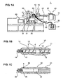
- FIG. 1A is a side view showing an entire structure of a fiber filler reinforced resin injection molding apparatus according to a first embodiment of the present invention
- FIG. 1B is a sectional view showing a cylinder inside of a plasticizing pushing portion
- FIG. 1C is a sectional view showing a structure of a major portion of the cylinder inside of the plasticizing pushing portion.
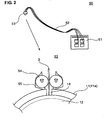
- FIG. 2 is a partially sectional view showing a GF supply unit with a seal structure that prevents a leakage of a foaming agent at the GF supply portion in the first embodiment.
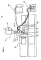
- FIG. 4 is an explanatory diagram showing a schematic structure of a device to compensate a leakage of a physical foaming agent at a GF supply portion of a filler reinforced resin injection molding apparatus according to a third embodiment.
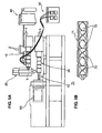
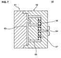
- FIG. 7 is a sectional view of a mold in which the mixing nozzle and a similar agitating device are provided at a hot runner portion.
- the resin collection portion 20 collects the resin composite 5 transmitted from the plasticizing pushing portion 10 in the collector 21 temporarily.
- the resin composite 5 in the collector 21 is controlled so as to be transmitted to a junction portion 33 of the metering injecting portion 30 by a valve 22 that is provided at a downward or downstream end (outlet) of the collector 21.
- the metering injecting portion 30 preferably is configured to be an injection unit in which an injection piston 32 is provided in the cylinder 31, and guides the resin composite 5 in the collector 21 to the junction portion 33 so as to make the reinforcement fiber 3 and the physical foaming agent 4 be mixed with the resin composite 5. Further, after metering of the resin composite for a necessary amount for molding, the resin composite 5 is configured to be injected into a cavity 63 (see FIG. 7 ) of the mold 60 with an opening/closing operation of a valve 35 that is provided at an injecting end 34 (outlet) and an reciprocating movement of the injection piston 32.
- valves 18, 22 and/or 35 that are opened or closed with the on-off operation.
- These valves 18, 22 and/or 35 allow the resin composite 5 to flow out when opening, and when closing, they stop the flow and preferably prevent counterflow of the resin composite 5 as well, ensuring a proper seal function.
- the reinforcement fiber 3 may not be broken or hurt by operations of the valves 18, 22 and/or 35.
- the SCF supply unit 40 guides the (physical or chemical) foaming agent 4 into the fiber filler reinforced resin injection molding apparatus 1, in which the foaming agent 4 is supplied into the cylinder 11 (the resin 2 ) at the foaming-agent supply portion 15 provided at the plasticizing pushing portion 10.
- the SCF supply unit 40 comprises a gas reservoir 41 with a raw gas stored therein, and a pressure-increase control portion 42 to increase a pressure of the raw gas from the gas reservoir 41 to a specified (predetermined or predeterminable) pressure and control a supply amount of the pressure-increased physical foaming agent into the cylinder 11.
- the GF supply unit 50 (as the preferred reinforcement fiber supply unit) supplies the reinforcement fiber 3 (preferably continuous glass fiber 3 in the present embodiment) to the reinforcement-fiber mixing portion 14 of the plasticizing pushing portion 10.
- the GF supply unit 50 comprises, as shown in FIG. 2 , a GF storage portion 51 that stores the reinforcement fiber (preferably the substantially round glass fiber 3) in a coil shape therein with a proper seal, a GF supply portion 53 that is connected to the reinforcement-fiber mixing portion 15, a flexible supply pipe 52 that interconnects the GF storage portion 51 and the GF supply portion 53 and supplies the reinforcement fiber (preferably glass fiber) 3 therein.
- the GF supply portion 53 of the present embodiment comprises a fiber supply roller 54 to supply the reinforcement fiber (preferably glass fiber) 3 with its rotation, and a seal member 55 that can provide proper sealing between side walls of the cylinder 11 (cylinder barrel 11 a), in which the roller 54 is held by the seal member 55 so as to be pushed substantially against a periphery of an opening of the reinforcement-fiber mixing portion 14. Accordingly, the portions 51, 52 and 53 are connected with proper sealing (air- or fluid-tightness), and the inside circumference is properly shut off from an outside atmosphere with the sealing. Thereby, the (physical or chemical) foaming agent 4 and the resin composite 5 containing the foaming agent 4, which have been supplied into the cylinder 11, are prevented from leaking out from the reinforcement-fiber mixing portion 14 (GF supply portion 53, GF supply unit 50).
- the continuous glass fiber 3 is supplied into the cylinder 11 of the plasticizing pushing portion 10 by the roller 54 with its rotation, where the fiber 3 is cut into pieces preferably by a shearing force of the screw 12 rotating in the cylinder 11.
- a length of the fiber pieces preferably can be adjusted by the rotational speed of the screw 12, the relative friction force between the fiber 3 and the roller 54 and/or the supply speed of the fiber 3 by the roller 54.
- the mixing portion 14 of the reinforcement fiber 3 preferably is located downstream of the anti counterflow portion 13 of the screw 12.
- the supply portion 15 of the (physical or chemical) foaming agent 4 preferably is (likewise) located downstream of the anti counterflow portion 13 of the screw 12 and/or upstream of the mixing portion 14 of the reinforcement fiber 3.
- the reinforcement fiber 3 is mixed with resin 2 that has reduced its viscosity with the (physical or chemical) foaming agent 4, so that the mixing and dispersion of the reinforcement fiber 3 can be improved. Also, the mixed fiber 3 is transmitted downward by the (physical or chemical) foaming agent 4, so it may not go upstream.
- the reinforcement fiber 3 is mixed with the resin 2 preferably at the portion (mixing portion 14 ) located downstream of the supply portion of the (physical or chemical) foaming agent 4 (supply portion 15 ). Accordingly, the reinforcement fiber 3 is mixed with resin 2 that has reduced its viscosity with the (physical or chemical) foaming agent 4, so that the mixing and dispersion of the reinforcement fiber 3 in the resin composite 5 can be improved.
- thermoplastic resin preferably is used as the following resin 2, and the following thermoplastic resin may be applied; polyethylene-based resin, polypropylene-based resin, acrylonitrile-butadiene-styrene copolymer (ABS resin), polystyrene-based resin, polycarbonate-based resin, polyethylene terephthalate, polybutylene terephthalate, acrylonitrile-styrene copolymer (AS resin), sybdiotactic polystyrene, polymethyl methacrylate, polyphenylene sulfide, polyether sulfone, polyarylate, polyamide, polyimide, liquid crystal resin, polyphenylene oxide, polyacetal, polyethylene naphthalate, and so on.
- ABS resin acrylonitrile-butadiene-styrene copolymer
- AS resin acrylonitrile-styrene copolymer
- AS resin acrylonitrile-styrene copo
- reinforcement fiber 3 glass fiber, carbon fiber, inorganic whisker, potassium titanate whisker, and so on preferably may be applied.
- the content of the thermoplastic resin 2 with respect to the thermoplastic resin composite 5 is preferably about 20 - about 95 wt%, more preferably about 60 - about 90 wt%. There is a concern of a poor flowing function or a weak mechanical rigidity if the content of the thermoplastic resin 2 is too small. Also, the content of the reinforcement fiber 3 with respect to the thermoplastic resin composite 5 is preferably about 0 - about 50 wt%, more preferably about 10 - about 40 wt%.
- thermoplastic resin composite 5 may be added an additive or changing agent, such as powder fillers, plasticizing agent, stabilizing agent, anti oxidant, ultraviolet-ray absorbent, anti-charging agent, flame retardant, or flame-resistant agent.
- an additive or changing agent such as powder fillers, plasticizing agent, stabilizing agent, anti oxidant, ultraviolet-ray absorbent, anti-charging agent, flame retardant, or flame-resistant agent.
- the physical foaming agent 4 (as the preferred foaming agent) in the present embodiment includes any foaming agent with a pressure lower than the super critical pressure, other than the super critical fluid in the super critical state (Super Critical Fluid: SCF), just excluding a chemical foaming agent that foams with a heat caused by a chemical reaction.
- a super critical fluid is a fluid that is in a state where the temperature and pressure of the fluid exceeds respectively the critical temperature and/or pressure that allow the at least partial coexistence of gas and liquid.
- the reinforcement-fiber mixing portion 14 is located downstream of the foaming-agent supply portion 15. Thereby, since the reinforcement fiber 3 is mixed with the resin 2 to which the foaming agent 4 is supplied, the reinforcement fiber 3 is mixed with resin 2 that has reduced its viscosity with the foaming agent 4. Thus, the mixing and dispersion of the reinforcement fiber 3 in the resin composite 5 can be improved.
- the resin composite 5 collected temporarily in the resin collection portion 20 is transmitted to the metering injecting portion 30, and after metering of the resin composite 5 for the necessary amount for molding, the resin composite 5 is supplied into the cavity 63 of the mold 60 via the metering injecting portion 30. Since this supply (confluence) promotes the mixing and dispersion of the reinforcement fiber 3 in the resin composite 5, the reinforcement fiber 3 can be dispersed uniformly. Thus, the fiber filler reinforced resin molded article with more excellent properties can be provided.
- the resin composite 5 plasticized at the plasticizing pushing portion 10 is supplied directly to the junction portion 33 of the metering injecting portion 30.
- the mixing and dispersion of the reinforcement fiber 3 and the (physical or chemical) foaming agent 4 in the resin composite 5 is attained, and after metering of the resin composite 5 for the necessary amount for molding, the resin composite 5 is injected into the cavity 63 of the mold 60.
- the leakage amount of the foaming agent 4 that has leaked from the reinforcement-fiber mixing portion 14 is detected by the flow-amount detecting device (flow meter 45 ) in the path (SCF guide pipe 44 ), and the foaming agent 4 can be supplemented by the amount corresponding to the leakage amount from the foaming-agent supply portion(s) 15, 15' .
- the necessary amount of the foaming agent 4 in the resin composite 5 can be substantially maintained, and the properties of the resin molded article having the desirable foaming ratio can be improved.
Landscapes
- Engineering & Computer Science (AREA)
- Mechanical Engineering (AREA)
- Injection Moulding Of Plastics Or The Like (AREA)
- Molding Of Porous Articles (AREA)
Claims (15)
- Formverfahren für einen mit Faserfüllstoff verstärkten Harzformgegenstand, worin eine Verstärkungsfaser (3) und ein Harz (2) in einem Materialzuführzylinder (11), einschließlich einer Schraube (12) mit einem Anti-Gegenstromabschnitt (13), plastifiziert und geknetet werden und das plastifizierte Harz (5) mit der damit gemischten Verstärkungsfaser (3) in einen Hohlraum (63) einer Form (60) injiziert wird,
wobei die Verstärkungsfaser (3) mit dem Harz (2) in dem Zylinder (11) gemischt wird, und ein Treibmittel bzw. Schaummittel in den Zylinder (11) an einem Abschnitt (15) im wesentlichen stromabwärts des Anti-Gegenstromabschnitts (13) der Schraube (12) zugeführt wird, dadurch gekennzeichnet, daß die Verstärkungsfaser mit dem Harz (2) in dem Zylinder (11) an einem Abschnitt (14) stromabwärts des Antigegenstromabschnitts (13) der Schraube (12) gemischt wird, und wobei der Anteil an Entweichen bzw. Ausströmen des Treibmittels (4) durch eine Fließmengendetektionsvorrichtung (15), angeordnet in der Entweichstrecke des Treibmittels (4), welches aus dem Verstärkungsfaser-Mischabschnitts (14) entweicht, detektiert wird, und die Menge des Treibmittels (14), entsprechend der Menge, die entwichen ist, aus dem Schäummittel-Zuführabschnitt (15) ergänzt wird. - Formverfahren für einen mit Faserfüllstoff verstärkten Harzstoffgegenstand gemäß Anspruch 1, wobei das Treibmittel (4) ein überkritisches Fluid ist.
- Formverfahren für einen mit Faserfüllstoff verstärkten Harzstoffgegenstand gemäß Anspruch 1 oder 2, wobei die Verstärkungsfaser (3) mit dem Harz (2) in dem Zylinder (11) an einem Abschnitt (14) gemischt wird, der im wesentlichen stromabwärts des Zuführabschnitts (15) des Treibmittels (4) angeordnet ist.
- Formverfahren für einen mit Faserfüllstoff verstärkten Harzstoffgegenstand gemäß einem der vorhergehenden Ansprüche, wobei die Verstärkungsfaser (3) unabhängig angeordnet ist, so daß sie mit dem Harz (2) gemischt wird.
- Formverfahren für einen mit Faserfüllstoff verstärkten Harzstoffgegenstand gemäß Anspruch 4, wobei die Verstärkungsfaser (3) in einer Form einer kontinuierlichen Faser zu dem Zylinder (11) bereitgestellt wird, und die bereitgestellte kontinuierliche Faser (3) in Stücke durch die Schraube (12) geschnitten wird, wobei die Verstärkungsfaser (3) mit dem Harz (2) in dem Zylinder (11) gemischt wird.
- Formverfahren für einen mit Faserfüllstoff verstärkten Harzstoffgegenstand gemäß einem der vorhergehenden Ansprüche, wobei das Mischen und die Dispersion der Verstärkungsfaser (3) in dem Harz (5) in einer Harzfließwegstrecke von dem Zuführabschnitt (15) des Treibmittels (4) zu dem Hohlraum (63) der Form (60) unterstützt wird.
- Formverfahren für einen mit Faserfüllstoff verstärkten Harzstoffgegenstand gemäß einem der vorhergehenden Ansprüche, wobei das Harz (5) mit dem dazu zugeführten Treibmittel (4) und die damit gemischte Verstärkungsfaser (3) temporär gesammelt wird, zu einer Injektionseinheit (30) überführt wird, zum Formen dosiert wird und anschließend zu dem Hohlraum (63) der Form (60) über die Injektionseinheit (30) zugeführt wird.
- Formvorrichtung (1, 1A) für einen mit Faserfüllstoff verstärkten Harzformgegenstand, worin eine Verstärkungsfaser (3) und ein Harz (2) in einem Materialzuführzylinder (11), einschließlich einer Schraube (12) mit einem Anti-Gegenstromabschnitt (12), plastifiziert und geknetet werden, und das plastifizierte Harz (5) mit der damit gemischten Verstärkungsfaser (3) in einen Hohlraum (63) einer Form (60) injiziert wird, wobei die Formvorrichtung (1, 1 A) umfaßt:einen Verstärkungsfaser-Mischabschnitt (14), wobei die Verstärkungsfaser (3) mit dem Harz (2) in dem Zylinder (11) gemischt wird, wobei der Mischabschnitt (14) stromabwärts des Anti-Gegenstromabschnitts (13) der Schraube (12) angeordnet ist, undeinen Treibmittel-Zuführabschnitt (15), bei welchem ein Treibmittel (4) in den Zylinder (11) zugeführt wird, wobei der Zuführabschnitt (15) im wesentlichen stromabwärts des Anti-Gegenstromabschnitts (13) der Schraube (12) angeordnet ist, dadurch gekennzeichnet, daß eine Fließmengendetektionsvorrichtung (45) vorgesehen ist, die in einer Ausweichwegstrecke des Treibmittels (4), welches von dem Verstärkungsfaser-Mischabschnitt (14) entweicht, angeordnet ist und eine Menge des Entweichens des Treibmittels (4) detektiert, und wobei das Treibmittel (4) konfiguriert ist, von dem Treibmittelzuführabschnitt (15) im wesentlichen gemäß der Entweichmenge davon, detektiert durch die Fließmengen-Detektionsvorrichtung (45), ergänzt zu werden.
- Formvorrichtung (1, 1A) für einen mit Faserfüllstoff verstärkten Harzformgegenstand, wobei das Treibmittel (4) ein superkritisches Fluid ist.
- Formvorrichtung (1, 1A) für einen mit Faserfüllstoff verstärkten Harzstoffgegenstand gemäß Anspruch 8 oder 9, wobei die Verstärkungsfaser (3) mit dem Harz (2) in dem Zylinder (11) an einem Abschnitt (14) gemischt wird, der im wesentlichen stromabwärts des Zuführabschnitts (15) des Treibmittels (4) angeordnet ist.
- Formvorrichtung (1, 1A) für einen mit Faserfüllstoff verstärkten Harzstoffgegenstand gemäß einem der Ansprüche 8 bis 10, wobei die Verstärkungsfaser (3) unabhängig angeordnet ist, so daß sie mit dem Harz (2) gemischt wird.
- Formvorrichtung (1, 1A) für einen mit Faserfüllstoff verstärkten Harzstoffgegenstand gemäß Anspruch 11, wobei die Verstärkungsfaser (3) in einer Form einer kontinuierlichen Faser zu dem Zylinder (11) bereitgestellt wird, und die bereitgestellte kontinuierliche Faser (3) in Stücke durch die Schraube (12) geschnitten wird, wobei die Verstärkungsfaser (3) mit dem Harz (2) in dem Zylinder (11) gemischt wird.
- Formvorrichtung (1, 1A) für einen mit Faserfüllstoff verstärkten Harzstoffgegenstand gemäß einem der Ansprüche 8 bis 12, wobei eine Misch-Dispersionsfördervorrichtung (70, 36A, 36B, 37, 67) angeordnet ist, um das Mischen und die Dispersion der Verstärkungsfaser (3) in dem Harz (5) in einer Harzfließwegstrecke von dem Zuführabschnitt (15) des Treibmittels (4) zu dem Hohlraum (63) der Form (60) zu unterstützen.
- Formvorrichtung (1, 1A) für einen mit Faserfüllstoff verstärkten Harzstoffgegenstand gemäß einem der Ansprüche 8 bis 13, wobei das Harz (5) mit dem dazu zugeführten Treibmittel (4) und die damit gemischte Verstärkungsfaser (3) temporär gesammelt wird, zu einer Injektionseinheit (30) überführt wird, zum Formen dosiert wird und anschließend zu dem Hohlraum (63) der Form (60) über die Injektionseinheit (30) zugeführt wird.
- Formvorrichtung (1; 1A) für einen mit Faserfüllstoff verstärkten Harzstoffgegenstand gemäß einem der Ansprüche 8 bis 14, wobei eine Abdichtungsvorrichtung (55; 59) angeordnet ist, um eine Innenseite von einer Außenseite des Zylinders (11) an dem Verstärkungsfaser-Mischabschnitt (14) abzudichten.
Applications Claiming Priority (1)
| Application Number | Priority Date | Filing Date | Title |
|---|---|---|---|
| JP2006026306A JP4797661B2 (ja) | 2006-02-02 | 2006-02-02 | 繊維強化樹脂成形品の成形方法および成形装置 |
Publications (2)
| Publication Number | Publication Date |
|---|---|
| EP1815962A1 EP1815962A1 (de) | 2007-08-08 |
| EP1815962B1 true EP1815962B1 (de) | 2009-09-30 |
Family
ID=37969707
Family Applications (1)
| Application Number | Title | Priority Date | Filing Date |
|---|---|---|---|
| EP07001521A Ceased EP1815962B1 (de) | 2006-02-02 | 2007-01-24 | Verfahren zum Formen eines Gegenstandes von mit Glasfasern verstärktem Harzmaterial |
Country Status (4)
| Country | Link |
|---|---|
| US (1) | US20070176313A1 (de) |
| EP (1) | EP1815962B1 (de) |
| JP (1) | JP4797661B2 (de) |
| DE (1) | DE602007002575D1 (de) |
Families Citing this family (19)
| Publication number | Priority date | Publication date | Assignee | Title |
|---|---|---|---|---|
| JP4748365B2 (ja) * | 2006-06-23 | 2011-08-17 | マツダ株式会社 | 繊維強化樹脂成形品の成形方法及び成形装置 |
| HUE030314T2 (hu) * | 2007-09-05 | 2017-04-28 | Smp Deutschland Gmbh | Eljárás és berendezés szálerõsítésû mûanyag formadarabok elõállítására |
| JP5846998B2 (ja) * | 2012-03-30 | 2016-01-20 | 東芝機械株式会社 | 可塑化装置、射出装置、射出成形装置、押出機、及び成形品の製造方法 |
| JP5941727B2 (ja) * | 2012-03-30 | 2016-06-29 | 東芝機械株式会社 | スクリュ、可塑化装置、射出装置、射出成形装置、押出機、及び成形品の製造方法 |
| US9517583B2 (en) * | 2012-12-11 | 2016-12-13 | Ford Global Technologies, Llc | Method of forming natural fiber polymer composite |
| JP5802689B2 (ja) * | 2013-01-16 | 2015-10-28 | 日精樹脂工業株式会社 | 二液用射出機 |
| JP5649244B2 (ja) * | 2013-02-28 | 2015-01-07 | 株式会社 日本油機 | ベント式射出成形機のベント口より長繊維及び/又は各種添加物を直接投入する樹脂成形品の製造方法 |
| US9630346B2 (en) * | 2013-03-05 | 2017-04-25 | Wisconsin Alumni Research Foundation | Method of fabricating an injection molded component |
| JP6194232B2 (ja) * | 2013-11-12 | 2017-09-06 | 東芝機械株式会社 | 可塑化装置、成形装置、押出機、成形品の製造方法 |
| JP5940740B1 (ja) * | 2014-11-25 | 2016-06-29 | 三菱重工プラスチックテクノロジー株式会社 | 射出成形方法、及び、射出成形機 |
| JP6069470B1 (ja) * | 2015-12-09 | 2017-02-01 | 東芝機械株式会社 | 射出装置、射出成形機及び射出方法 |
| JP6838865B2 (ja) * | 2016-03-31 | 2021-03-03 | 宇部興産機械株式会社 | 射出成形装置および射出成形方法 |
| DE102017123992A1 (de) * | 2017-10-16 | 2019-04-18 | Kraussmaffei Technologies Gmbh | Einschnecken-Plastifiziereinheit |
| DE102018118883B3 (de) | 2018-08-03 | 2020-01-16 | Kraussmaffei Technologies Gmbh | Verfahren und Vorrichtung zur Herstellung eines faserverstärkten Plastifikats und Verwendung der Vorrichtung zur additiven Fertigung |
| JP7193376B2 (ja) * | 2019-02-22 | 2022-12-20 | Towa株式会社 | 樹脂成型装置及び樹脂成型品の製造方法 |
| US12053912B2 (en) * | 2020-07-13 | 2024-08-06 | King Steel Machinery Co., Ltd. | Extruding system and method of extruding a mixture of a polymeric material and a blowing agent |
| JP7625447B2 (ja) * | 2021-03-11 | 2025-02-03 | 本田技研工業株式会社 | 繊維強化樹脂成形品の製造装置及び製造方法 |
| AT526871B1 (de) * | 2023-01-30 | 2025-06-15 | Engel Austria Gmbh | Formgebungsmaschine zum Herstellen von Formteilen |
| AT526872B1 (de) * | 2023-01-30 | 2025-12-15 | Engel Austria Gmbh | Formgebungsmaschine zum Herstellen von Formteilen |
Family Cites Families (17)
| Publication number | Priority date | Publication date | Assignee | Title |
|---|---|---|---|---|
| DE3939954A1 (de) * | 1989-12-02 | 1991-06-06 | Hennecke Gmbh Maschf | Verfahren und vorrichtung zum herstellen von kunststoffen, insbesondere schaumstoffen |
| US5707571A (en) * | 1991-03-28 | 1998-01-13 | Reedy; Michael Edward | Process for producing fiber reinforced foam having a random orientations of fibers |
| JPH09286036A (ja) * | 1996-04-22 | 1997-11-04 | Toray Ind Inc | 樹脂成形品 |
| JP2000108190A (ja) * | 1998-10-02 | 2000-04-18 | Sekisui Chem Co Ltd | 繊維複合成形体及びその製造法 |
| US6322347B1 (en) * | 1999-04-02 | 2001-11-27 | Trexel, Inc. | Methods for manufacturing foam material including systems with pressure restriction element |
| US7172333B2 (en) * | 1999-04-02 | 2007-02-06 | Southco, Inc. | Injection molding screw |
| JP4224894B2 (ja) * | 1999-06-04 | 2009-02-18 | チッソ株式会社 | 複合強化ポリオレフィン樹脂組成物の製造方法及びその製造装置 |
| JP3590559B2 (ja) * | 2000-03-14 | 2004-11-17 | 積水化学工業株式会社 | 熱可塑性樹脂成形品の射出成形装置 |
| EP1293319A4 (de) * | 2000-05-31 | 2006-05-24 | Asahi Chemical Ind | Spritzgie verfahren |
| US6602063B1 (en) * | 2000-07-21 | 2003-08-05 | Trexel, Inc. | Discontinuous blowing agent delivery system and method |
| DE10037773C1 (de) * | 2000-08-03 | 2002-08-22 | Hennecke Gmbh | Verfahren und Vorrichtung zum Herstellen von mit Langfasern verstärkten Kunststoff-Formteilen |
| EP1335827B1 (de) * | 2000-09-29 | 2018-03-07 | Trexel, Inc. | Faserfüllerformartikel |
| DE10062659B4 (de) * | 2000-12-15 | 2005-09-22 | Demag Ergotech Gmbh | Aufschäummittelbeladungs- und Mischvorrichtung |
| JP3425559B2 (ja) * | 2001-01-11 | 2003-07-14 | 積水化学工業株式会社 | 熱可塑性樹脂成形品の射出成形装置 |
| DE10118486B4 (de) * | 2001-04-12 | 2009-08-13 | Sumitomo (Shi) Demag Plastics Machinery Gmbh | Spritzeinheit für Spritzgießmaschinen mit kontinuierlich arbeitender Plastifiziereinheit |
| US20030003291A1 (en) * | 2001-07-02 | 2003-01-02 | Shah Suresh D. | Foamed thermoplastic resin having fiber reinforcing and apparatuses for making |
| US7144532B2 (en) * | 2002-10-28 | 2006-12-05 | Trexel, Inc. | Blowing agent introduction systems and methods |
-
2006
- 2006-02-02 JP JP2006026306A patent/JP4797661B2/ja not_active Expired - Fee Related
- 2006-12-08 US US11/635,492 patent/US20070176313A1/en not_active Abandoned
-
2007
- 2007-01-24 EP EP07001521A patent/EP1815962B1/de not_active Ceased
- 2007-01-24 DE DE602007002575T patent/DE602007002575D1/de active Active
Also Published As
| Publication number | Publication date |
|---|---|
| JP4797661B2 (ja) | 2011-10-19 |
| EP1815962A1 (de) | 2007-08-08 |
| DE602007002575D1 (de) | 2009-11-12 |
| US20070176313A1 (en) | 2007-08-02 |
| JP2007203638A (ja) | 2007-08-16 |
Similar Documents
| Publication | Publication Date | Title |
|---|---|---|
| EP1815962B1 (de) | Verfahren zum Formen eines Gegenstandes von mit Glasfasern verstärktem Harzmaterial | |
| EP1815963B1 (de) | Formverfahren eines faserverstärkten Harzverbundwerkstoffs und entsprechende Vorrichtung | |
| US11241816B2 (en) | Process and device for producing molded foam | |
| EP1556201B1 (de) | Vorrichtung und verfahren zur verarbeitung von ein treibmittel enthaltenden polymeren | |
| CA2618877C (en) | Method for multilayer molding of thermoplastic resins and multilayer molding apparatus | |
| JP3590559B2 (ja) | 熱可塑性樹脂成形品の射出成形装置 | |
| EP2737989B1 (de) | Verfahren und vorrichtung zur herstellung eines rohrelements | |
| KR20190142427A (ko) | 발포 성형체의 제조 방법 및 제조 장치 | |
| CN102481715A (zh) | 用于制造塑料成型件的装置及其应用 | |
| CN100369733C (zh) | 用于热塑性树脂模制件的模制设备 | |
| CN105073373A (zh) | 发泡性注射成形体的制造方法及其注射装置 | |
| JP7370266B2 (ja) | 射出成形方法および射出成形装置 | |
| US11820063B2 (en) | Manufacturing method and manufacturing device for foam molded article | |
| JP4748365B2 (ja) | 繊維強化樹脂成形品の成形方法及び成形装置 | |
| JP2001277328A (ja) | 熱可塑性樹脂成形体の製造装置及び製造方法 | |
| JP2012116047A (ja) | 射出成形方法及び射出成形装置 | |
| JP2001191360A (ja) | シリコーンゴム複合成形品及び成形方法 |
Legal Events
| Date | Code | Title | Description |
|---|---|---|---|
| PUAI | Public reference made under article 153(3) epc to a published international application that has entered the european phase |
Free format text: ORIGINAL CODE: 0009012 |
|
| AK | Designated contracting states |
Kind code of ref document: A1 Designated state(s): AT BE BG CH CY CZ DE DK EE ES FI FR GB GR HU IE IS IT LI LT LU LV MC NL PL PT RO SE SI SK TR |
|
| AX | Request for extension of the european patent |
Extension state: AL BA HR MK RS |
|
| 17P | Request for examination filed |
Effective date: 20080103 |
|
| 17Q | First examination report despatched |
Effective date: 20080225 |
|
| AKX | Designation fees paid |
Designated state(s): DE |
|
| GRAP | Despatch of communication of intention to grant a patent |
Free format text: ORIGINAL CODE: EPIDOSNIGR1 |
|
| GRAS | Grant fee paid |
Free format text: ORIGINAL CODE: EPIDOSNIGR3 |
|
| GRAA | (expected) grant |
Free format text: ORIGINAL CODE: 0009210 |
|
| AK | Designated contracting states |
Kind code of ref document: B1 Designated state(s): DE |
|
| REF | Corresponds to: |
Ref document number: 602007002575 Country of ref document: DE Date of ref document: 20091112 Kind code of ref document: P |
|
| PLBE | No opposition filed within time limit |
Free format text: ORIGINAL CODE: 0009261 |
|
| STAA | Information on the status of an ep patent application or granted ep patent |
Free format text: STATUS: NO OPPOSITION FILED WITHIN TIME LIMIT |
|
| 26N | No opposition filed |
Effective date: 20100701 |
|
| PGFP | Annual fee paid to national office [announced via postgrant information from national office to epo] |
Ref country code: DE Payment date: 20200114 Year of fee payment: 14 |
|
| REG | Reference to a national code |
Ref country code: DE Ref legal event code: R119 Ref document number: 602007002575 Country of ref document: DE |
|
| PG25 | Lapsed in a contracting state [announced via postgrant information from national office to epo] |
Ref country code: DE Free format text: LAPSE BECAUSE OF NON-PAYMENT OF DUE FEES Effective date: 20210803 |