EP1815962B1 - Molding method of a fiber filler reinforced resin molded article - Google Patents
Molding method of a fiber filler reinforced resin molded article Download PDFInfo
- Publication number
- EP1815962B1 EP1815962B1 EP07001521A EP07001521A EP1815962B1 EP 1815962 B1 EP1815962 B1 EP 1815962B1 EP 07001521 A EP07001521 A EP 07001521A EP 07001521 A EP07001521 A EP 07001521A EP 1815962 B1 EP1815962 B1 EP 1815962B1
- Authority
- EP
- European Patent Office
- Prior art keywords
- fiber
- resin
- reinforcement
- foaming agent
- molded article
- Prior art date
- Legal status (The legal status is an assumption and is not a legal conclusion. Google has not performed a legal analysis and makes no representation as to the accuracy of the status listed.)
- Expired - Fee Related
Links
- 239000000835 fiber Substances 0.000 title claims description 210
- 229920005989 resin Polymers 0.000 title claims description 143
- 239000011347 resin Substances 0.000 title claims description 143
- 238000000465 moulding Methods 0.000 title claims description 50
- 239000000945 filler Substances 0.000 title claims description 45
- 238000000034 method Methods 0.000 title claims description 35
- 239000004088 foaming agent Substances 0.000 claims description 127
- 230000002787 reinforcement Effects 0.000 claims description 111
- 239000006185 dispersion Substances 0.000 claims description 37
- 238000002347 injection Methods 0.000 claims description 25
- 239000007924 injection Substances 0.000 claims description 25
- 239000012530 fluid Substances 0.000 claims description 24
- 230000001737 promoting effect Effects 0.000 claims description 8
- 239000000463 material Substances 0.000 claims description 6
- 239000000805 composite resin Substances 0.000 description 60
- 239000000126 substance Substances 0.000 description 48
- 239000003365 glass fiber Substances 0.000 description 30
- 229920005992 thermoplastic resin Polymers 0.000 description 12
- 238000011144 upstream manufacturing Methods 0.000 description 12
- 238000001746 injection moulding Methods 0.000 description 11
- CURLTUGMZLYLDI-UHFFFAOYSA-N Carbon dioxide Chemical compound O=C=O CURLTUGMZLYLDI-UHFFFAOYSA-N 0.000 description 8
- 239000007789 gas Substances 0.000 description 8
- 230000007246 mechanism Effects 0.000 description 8
- 239000006260 foam Substances 0.000 description 7
- 238000005187 foaming Methods 0.000 description 7
- IJGRMHOSHXDMSA-UHFFFAOYSA-N Atomic nitrogen Chemical compound N#N IJGRMHOSHXDMSA-UHFFFAOYSA-N 0.000 description 6
- 239000003795 chemical substances by application Substances 0.000 description 6
- 230000008569 process Effects 0.000 description 5
- 238000007789 sealing Methods 0.000 description 5
- 239000004793 Polystyrene Substances 0.000 description 4
- 239000001569 carbon dioxide Substances 0.000 description 4
- 229910002092 carbon dioxide Inorganic materials 0.000 description 4
- 210000000497 foam cell Anatomy 0.000 description 4
- 230000004048 modification Effects 0.000 description 4
- 238000012986 modification Methods 0.000 description 4
- 229920002223 polystyrene Polymers 0.000 description 4
- 229910052757 nitrogen Inorganic materials 0.000 description 3
- -1 polyethylene terephthalate Polymers 0.000 description 3
- 229920005673 polypropylene based resin Polymers 0.000 description 3
- 239000004734 Polyphenylene sulfide Substances 0.000 description 2
- 229920000122 acrylonitrile butadiene styrene Polymers 0.000 description 2
- 230000000694 effects Effects 0.000 description 2
- 238000010438 heat treatment Methods 0.000 description 2
- 238000004898 kneading Methods 0.000 description 2
- 229910052751 metal Inorganic materials 0.000 description 2
- 239000002184 metal Substances 0.000 description 2
- 239000004417 polycarbonate Substances 0.000 description 2
- 229920000515 polycarbonate Polymers 0.000 description 2
- 229920000069 polyphenylene sulfide Polymers 0.000 description 2
- 230000009467 reduction Effects 0.000 description 2
- 238000003860 storage Methods 0.000 description 2
- 239000013585 weight reducing agent Substances 0.000 description 2
- RNFJDJUURJAICM-UHFFFAOYSA-N 2,2,4,4,6,6-hexaphenoxy-1,3,5-triaza-2$l^{5},4$l^{5},6$l^{5}-triphosphacyclohexa-1,3,5-triene Chemical compound N=1P(OC=2C=CC=CC=2)(OC=2C=CC=CC=2)=NP(OC=2C=CC=CC=2)(OC=2C=CC=CC=2)=NP=1(OC=1C=CC=CC=1)OC1=CC=CC=C1 RNFJDJUURJAICM-UHFFFAOYSA-N 0.000 description 1
- 229910000838 Al alloy Inorganic materials 0.000 description 1
- 229920000049 Carbon (fiber) Polymers 0.000 description 1
- 229910000975 Carbon steel Inorganic materials 0.000 description 1
- 229910000881 Cu alloy Inorganic materials 0.000 description 1
- 229930182556 Polyacetal Natural products 0.000 description 1
- 239000004952 Polyamide Substances 0.000 description 1
- 239000004695 Polyether sulfone Substances 0.000 description 1
- 239000004642 Polyimide Substances 0.000 description 1
- 239000004721 Polyphenylene oxide Substances 0.000 description 1
- 229910000831 Steel Inorganic materials 0.000 description 1
- XECAHXYUAAWDEL-UHFFFAOYSA-N acrylonitrile butadiene styrene Chemical compound C=CC=C.C=CC#N.C=CC1=CC=CC=C1 XECAHXYUAAWDEL-UHFFFAOYSA-N 0.000 description 1
- 239000004676 acrylonitrile butadiene styrene Substances 0.000 description 1
- 229920001893 acrylonitrile styrene Polymers 0.000 description 1
- 239000000654 additive Substances 0.000 description 1
- 230000000996 additive effect Effects 0.000 description 1
- 239000003963 antioxidant agent Substances 0.000 description 1
- 230000003078 antioxidant effect Effects 0.000 description 1
- 235000006708 antioxidants Nutrition 0.000 description 1
- 239000004917 carbon fiber Substances 0.000 description 1
- 239000010962 carbon steel Substances 0.000 description 1
- 238000006243 chemical reaction Methods 0.000 description 1
- 239000002131 composite material Substances 0.000 description 1
- 230000001419 dependent effect Effects 0.000 description 1
- 238000010586 diagram Methods 0.000 description 1
- NJLLQSBAHIKGKF-UHFFFAOYSA-N dipotassium dioxido(oxo)titanium Chemical compound [K+].[K+].[O-][Ti]([O-])=O NJLLQSBAHIKGKF-UHFFFAOYSA-N 0.000 description 1
- 239000003063 flame retardant Substances 0.000 description 1
- 239000011261 inert gas Substances 0.000 description 1
- 230000002452 interceptive effect Effects 0.000 description 1
- 239000007788 liquid Substances 0.000 description 1
- 239000004973 liquid crystal related substance Substances 0.000 description 1
- 238000004519 manufacturing process Methods 0.000 description 1
- 238000002844 melting Methods 0.000 description 1
- 230000008018 melting Effects 0.000 description 1
- VNWKTOKETHGBQD-UHFFFAOYSA-N methane Chemical compound C VNWKTOKETHGBQD-UHFFFAOYSA-N 0.000 description 1
- QJGQUHMNIGDVPM-UHFFFAOYSA-N nitrogen group Chemical group [N] QJGQUHMNIGDVPM-UHFFFAOYSA-N 0.000 description 1
- 239000008188 pellet Substances 0.000 description 1
- 229920003207 poly(ethylene-2,6-naphthalate) Polymers 0.000 description 1
- 229920003229 poly(methyl methacrylate) Polymers 0.000 description 1
- 229920002647 polyamide Polymers 0.000 description 1
- 229920001230 polyarylate Polymers 0.000 description 1
- 229920001707 polybutylene terephthalate Polymers 0.000 description 1
- 229920006393 polyether sulfone Polymers 0.000 description 1
- 229920005678 polyethylene based resin Polymers 0.000 description 1
- 239000011112 polyethylene naphthalate Substances 0.000 description 1
- 239000005020 polyethylene terephthalate Substances 0.000 description 1
- 229920000139 polyethylene terephthalate Polymers 0.000 description 1
- 229920001721 polyimide Polymers 0.000 description 1
- 229920002959 polymer blend Polymers 0.000 description 1
- 239000004926 polymethyl methacrylate Substances 0.000 description 1
- 229920006324 polyoxymethylene Polymers 0.000 description 1
- 229920006380 polyphenylene oxide Polymers 0.000 description 1
- 239000000843 powder Substances 0.000 description 1
- 238000003825 pressing Methods 0.000 description 1
- SCUZVMOVTVSBLE-UHFFFAOYSA-N prop-2-enenitrile;styrene Chemical compound C=CC#N.C=CC1=CC=CC=C1 SCUZVMOVTVSBLE-UHFFFAOYSA-N 0.000 description 1
- 239000012783 reinforcing fiber Substances 0.000 description 1
- 238000010008 shearing Methods 0.000 description 1
- 239000003381 stabilizer Substances 0.000 description 1
- 239000010959 steel Substances 0.000 description 1
- 239000012801 ultraviolet ray absorbent Substances 0.000 description 1
Images


Classifications
-
- B—PERFORMING OPERATIONS; TRANSPORTING
- B29—WORKING OF PLASTICS; WORKING OF SUBSTANCES IN A PLASTIC STATE IN GENERAL
- B29C—SHAPING OR JOINING OF PLASTICS; SHAPING OF MATERIAL IN A PLASTIC STATE, NOT OTHERWISE PROVIDED FOR; AFTER-TREATMENT OF THE SHAPED PRODUCTS, e.g. REPAIRING
- B29C44/00—Shaping by internal pressure generated in the material, e.g. swelling or foaming ; Producing porous or cellular expanded plastics articles
- B29C44/02—Shaping by internal pressure generated in the material, e.g. swelling or foaming ; Producing porous or cellular expanded plastics articles for articles of definite length, i.e. discrete articles
- B29C44/12—Incorporating or moulding on preformed parts, e.g. inserts or reinforcements
-
- B—PERFORMING OPERATIONS; TRANSPORTING
- B29—WORKING OF PLASTICS; WORKING OF SUBSTANCES IN A PLASTIC STATE IN GENERAL
- B29B—PREPARATION OR PRETREATMENT OF THE MATERIAL TO BE SHAPED; MAKING GRANULES OR PREFORMS; RECOVERY OF PLASTICS OR OTHER CONSTITUENTS OF WASTE MATERIAL CONTAINING PLASTICS
- B29B7/00—Mixing; Kneading
- B29B7/30—Mixing; Kneading continuous, with mechanical mixing or kneading devices
- B29B7/32—Mixing; Kneading continuous, with mechanical mixing or kneading devices with non-movable mixing or kneading devices
- B29B7/325—Static mixers
-
- B—PERFORMING OPERATIONS; TRANSPORTING
- B29—WORKING OF PLASTICS; WORKING OF SUBSTANCES IN A PLASTIC STATE IN GENERAL
- B29B—PREPARATION OR PRETREATMENT OF THE MATERIAL TO BE SHAPED; MAKING GRANULES OR PREFORMS; RECOVERY OF PLASTICS OR OTHER CONSTITUENTS OF WASTE MATERIAL CONTAINING PLASTICS
- B29B7/00—Mixing; Kneading
- B29B7/30—Mixing; Kneading continuous, with mechanical mixing or kneading devices
- B29B7/58—Component parts, details or accessories; Auxiliary operations
- B29B7/60—Component parts, details or accessories; Auxiliary operations for feeding, e.g. end guides for the incoming material
-
- B—PERFORMING OPERATIONS; TRANSPORTING
- B29—WORKING OF PLASTICS; WORKING OF SUBSTANCES IN A PLASTIC STATE IN GENERAL
- B29B—PREPARATION OR PRETREATMENT OF THE MATERIAL TO BE SHAPED; MAKING GRANULES OR PREFORMS; RECOVERY OF PLASTICS OR OTHER CONSTITUENTS OF WASTE MATERIAL CONTAINING PLASTICS
- B29B7/00—Mixing; Kneading
- B29B7/80—Component parts, details or accessories; Auxiliary operations
- B29B7/88—Adding charges, i.e. additives
- B29B7/90—Fillers or reinforcements, e.g. fibres
-
- B—PERFORMING OPERATIONS; TRANSPORTING
- B29—WORKING OF PLASTICS; WORKING OF SUBSTANCES IN A PLASTIC STATE IN GENERAL
- B29C—SHAPING OR JOINING OF PLASTICS; SHAPING OF MATERIAL IN A PLASTIC STATE, NOT OTHERWISE PROVIDED FOR; AFTER-TREATMENT OF THE SHAPED PRODUCTS, e.g. REPAIRING
- B29C44/00—Shaping by internal pressure generated in the material, e.g. swelling or foaming ; Producing porous or cellular expanded plastics articles
- B29C44/34—Auxiliary operations
- B29C44/3442—Mixing, kneading or conveying the foamable material
-
- B—PERFORMING OPERATIONS; TRANSPORTING
- B29—WORKING OF PLASTICS; WORKING OF SUBSTANCES IN A PLASTIC STATE IN GENERAL
- B29C—SHAPING OR JOINING OF PLASTICS; SHAPING OF MATERIAL IN A PLASTIC STATE, NOT OTHERWISE PROVIDED FOR; AFTER-TREATMENT OF THE SHAPED PRODUCTS, e.g. REPAIRING
- B29C44/00—Shaping by internal pressure generated in the material, e.g. swelling or foaming ; Producing porous or cellular expanded plastics articles
- B29C44/34—Auxiliary operations
- B29C44/60—Measuring, controlling or regulating
-
- B—PERFORMING OPERATIONS; TRANSPORTING
- B29—WORKING OF PLASTICS; WORKING OF SUBSTANCES IN A PLASTIC STATE IN GENERAL
- B29C—SHAPING OR JOINING OF PLASTICS; SHAPING OF MATERIAL IN A PLASTIC STATE, NOT OTHERWISE PROVIDED FOR; AFTER-TREATMENT OF THE SHAPED PRODUCTS, e.g. REPAIRING
- B29C48/00—Extrusion moulding, i.e. expressing the moulding material through a die or nozzle which imparts the desired form; Apparatus therefor
- B29C48/022—Extrusion moulding, i.e. expressing the moulding material through a die or nozzle which imparts the desired form; Apparatus therefor characterised by the choice of material
-
- B—PERFORMING OPERATIONS; TRANSPORTING
- B29—WORKING OF PLASTICS; WORKING OF SUBSTANCES IN A PLASTIC STATE IN GENERAL
- B29C—SHAPING OR JOINING OF PLASTICS; SHAPING OF MATERIAL IN A PLASTIC STATE, NOT OTHERWISE PROVIDED FOR; AFTER-TREATMENT OF THE SHAPED PRODUCTS, e.g. REPAIRING
- B29C48/00—Extrusion moulding, i.e. expressing the moulding material through a die or nozzle which imparts the desired form; Apparatus therefor
- B29C48/25—Component parts, details or accessories; Auxiliary operations
- B29C48/255—Flow control means, e.g. valves
-
- B—PERFORMING OPERATIONS; TRANSPORTING
- B29—WORKING OF PLASTICS; WORKING OF SUBSTANCES IN A PLASTIC STATE IN GENERAL
- B29C—SHAPING OR JOINING OF PLASTICS; SHAPING OF MATERIAL IN A PLASTIC STATE, NOT OTHERWISE PROVIDED FOR; AFTER-TREATMENT OF THE SHAPED PRODUCTS, e.g. REPAIRING
- B29C48/00—Extrusion moulding, i.e. expressing the moulding material through a die or nozzle which imparts the desired form; Apparatus therefor
- B29C48/25—Component parts, details or accessories; Auxiliary operations
- B29C48/285—Feeding the extrusion material to the extruder
- B29C48/288—Feeding the extrusion material to the extruder in solid form, e.g. powder or granules
- B29C48/2886—Feeding the extrusion material to the extruder in solid form, e.g. powder or granules of fibrous, filamentary or filling materials, e.g. thin fibrous reinforcements or fillers
-
- B—PERFORMING OPERATIONS; TRANSPORTING
- B29—WORKING OF PLASTICS; WORKING OF SUBSTANCES IN A PLASTIC STATE IN GENERAL
- B29C—SHAPING OR JOINING OF PLASTICS; SHAPING OF MATERIAL IN A PLASTIC STATE, NOT OTHERWISE PROVIDED FOR; AFTER-TREATMENT OF THE SHAPED PRODUCTS, e.g. REPAIRING
- B29C45/00—Injection moulding, i.e. forcing the required volume of moulding material through a nozzle into a closed mould; Apparatus therefor
- B29C45/17—Component parts, details or accessories; Auxiliary operations
- B29C45/46—Means for plasticising or homogenising the moulding material or forcing it into the mould
- B29C2045/466—Means for plasticising or homogenising the moulding material or forcing it into the mould supplying the injection unit directly by a compounder
-
- B—PERFORMING OPERATIONS; TRANSPORTING
- B29—WORKING OF PLASTICS; WORKING OF SUBSTANCES IN A PLASTIC STATE IN GENERAL
- B29C—SHAPING OR JOINING OF PLASTICS; SHAPING OF MATERIAL IN A PLASTIC STATE, NOT OTHERWISE PROVIDED FOR; AFTER-TREATMENT OF THE SHAPED PRODUCTS, e.g. REPAIRING
- B29C45/00—Injection moulding, i.e. forcing the required volume of moulding material through a nozzle into a closed mould; Apparatus therefor
- B29C45/17—Component parts, details or accessories; Auxiliary operations
- B29C45/26—Moulds
- B29C45/27—Sprue channels ; Runner channels or runner nozzles
- B29C45/30—Flow control means disposed within the sprue channel, e.g. "torpedo" construction
-
- B—PERFORMING OPERATIONS; TRANSPORTING
- B29—WORKING OF PLASTICS; WORKING OF SUBSTANCES IN A PLASTIC STATE IN GENERAL
- B29C—SHAPING OR JOINING OF PLASTICS; SHAPING OF MATERIAL IN A PLASTIC STATE, NOT OTHERWISE PROVIDED FOR; AFTER-TREATMENT OF THE SHAPED PRODUCTS, e.g. REPAIRING
- B29C45/00—Injection moulding, i.e. forcing the required volume of moulding material through a nozzle into a closed mould; Apparatus therefor
- B29C45/17—Component parts, details or accessories; Auxiliary operations
- B29C45/46—Means for plasticising or homogenising the moulding material or forcing it into the mould
- B29C45/47—Means for plasticising or homogenising the moulding material or forcing it into the mould using screws
- B29C45/48—Plasticising screw and injection screw comprising two separate screws
-
- B—PERFORMING OPERATIONS; TRANSPORTING
- B29—WORKING OF PLASTICS; WORKING OF SUBSTANCES IN A PLASTIC STATE IN GENERAL
- B29C—SHAPING OR JOINING OF PLASTICS; SHAPING OF MATERIAL IN A PLASTIC STATE, NOT OTHERWISE PROVIDED FOR; AFTER-TREATMENT OF THE SHAPED PRODUCTS, e.g. REPAIRING
- B29C45/00—Injection moulding, i.e. forcing the required volume of moulding material through a nozzle into a closed mould; Apparatus therefor
- B29C45/17—Component parts, details or accessories; Auxiliary operations
- B29C45/46—Means for plasticising or homogenising the moulding material or forcing it into the mould
- B29C45/53—Means for plasticising or homogenising the moulding material or forcing it into the mould using injection ram or piston
- B29C45/54—Means for plasticising or homogenising the moulding material or forcing it into the mould using injection ram or piston and plasticising screw
-
- B—PERFORMING OPERATIONS; TRANSPORTING
- B29—WORKING OF PLASTICS; WORKING OF SUBSTANCES IN A PLASTIC STATE IN GENERAL
- B29C—SHAPING OR JOINING OF PLASTICS; SHAPING OF MATERIAL IN A PLASTIC STATE, NOT OTHERWISE PROVIDED FOR; AFTER-TREATMENT OF THE SHAPED PRODUCTS, e.g. REPAIRING
- B29C45/00—Injection moulding, i.e. forcing the required volume of moulding material through a nozzle into a closed mould; Apparatus therefor
- B29C45/17—Component parts, details or accessories; Auxiliary operations
- B29C45/46—Means for plasticising or homogenising the moulding material or forcing it into the mould
- B29C45/56—Means for plasticising or homogenising the moulding material or forcing it into the mould using mould parts movable during or after injection, e.g. injection-compression moulding
- B29C45/568—Applying vibrations to the mould parts
-
- B—PERFORMING OPERATIONS; TRANSPORTING
- B29—WORKING OF PLASTICS; WORKING OF SUBSTANCES IN A PLASTIC STATE IN GENERAL
- B29C—SHAPING OR JOINING OF PLASTICS; SHAPING OF MATERIAL IN A PLASTIC STATE, NOT OTHERWISE PROVIDED FOR; AFTER-TREATMENT OF THE SHAPED PRODUCTS, e.g. REPAIRING
- B29C45/00—Injection moulding, i.e. forcing the required volume of moulding material through a nozzle into a closed mould; Apparatus therefor
- B29C45/17—Component parts, details or accessories; Auxiliary operations
- B29C45/46—Means for plasticising or homogenising the moulding material or forcing it into the mould
- B29C45/58—Details
- B29C45/581—Devices for influencing the material flow, e.g. "torpedo constructions" or mixing devices
-
- B—PERFORMING OPERATIONS; TRANSPORTING
- B29—WORKING OF PLASTICS; WORKING OF SUBSTANCES IN A PLASTIC STATE IN GENERAL
- B29C—SHAPING OR JOINING OF PLASTICS; SHAPING OF MATERIAL IN A PLASTIC STATE, NOT OTHERWISE PROVIDED FOR; AFTER-TREATMENT OF THE SHAPED PRODUCTS, e.g. REPAIRING
- B29C48/00—Extrusion moulding, i.e. expressing the moulding material through a die or nozzle which imparts the desired form; Apparatus therefor
- B29C48/025—General arrangement or layout of plant
-
- B—PERFORMING OPERATIONS; TRANSPORTING
- B29—WORKING OF PLASTICS; WORKING OF SUBSTANCES IN A PLASTIC STATE IN GENERAL
- B29C—SHAPING OR JOINING OF PLASTICS; SHAPING OF MATERIAL IN A PLASTIC STATE, NOT OTHERWISE PROVIDED FOR; AFTER-TREATMENT OF THE SHAPED PRODUCTS, e.g. REPAIRING
- B29C48/00—Extrusion moulding, i.e. expressing the moulding material through a die or nozzle which imparts the desired form; Apparatus therefor
- B29C48/03—Extrusion moulding, i.e. expressing the moulding material through a die or nozzle which imparts the desired form; Apparatus therefor characterised by the shape of the extruded material at extrusion
-
- B—PERFORMING OPERATIONS; TRANSPORTING
- B29—WORKING OF PLASTICS; WORKING OF SUBSTANCES IN A PLASTIC STATE IN GENERAL
- B29C—SHAPING OR JOINING OF PLASTICS; SHAPING OF MATERIAL IN A PLASTIC STATE, NOT OTHERWISE PROVIDED FOR; AFTER-TREATMENT OF THE SHAPED PRODUCTS, e.g. REPAIRING
- B29C48/00—Extrusion moulding, i.e. expressing the moulding material through a die or nozzle which imparts the desired form; Apparatus therefor
- B29C48/14—Extrusion moulding, i.e. expressing the moulding material through a die or nozzle which imparts the desired form; Apparatus therefor characterised by the particular extruding conditions, e.g. in a modified atmosphere or by using vibration
- B29C48/142—Extrusion moulding, i.e. expressing the moulding material through a die or nozzle which imparts the desired form; Apparatus therefor characterised by the particular extruding conditions, e.g. in a modified atmosphere or by using vibration using force fields, e.g. gravity or electrical fields
-
- B—PERFORMING OPERATIONS; TRANSPORTING
- B29—WORKING OF PLASTICS; WORKING OF SUBSTANCES IN A PLASTIC STATE IN GENERAL
- B29C—SHAPING OR JOINING OF PLASTICS; SHAPING OF MATERIAL IN A PLASTIC STATE, NOT OTHERWISE PROVIDED FOR; AFTER-TREATMENT OF THE SHAPED PRODUCTS, e.g. REPAIRING
- B29C48/00—Extrusion moulding, i.e. expressing the moulding material through a die or nozzle which imparts the desired form; Apparatus therefor
- B29C48/25—Component parts, details or accessories; Auxiliary operations
- B29C48/268—Throttling of the flow, e.g. for cooperating with plasticising elements or for degassing
-
- B—PERFORMING OPERATIONS; TRANSPORTING
- B29—WORKING OF PLASTICS; WORKING OF SUBSTANCES IN A PLASTIC STATE IN GENERAL
- B29C—SHAPING OR JOINING OF PLASTICS; SHAPING OF MATERIAL IN A PLASTIC STATE, NOT OTHERWISE PROVIDED FOR; AFTER-TREATMENT OF THE SHAPED PRODUCTS, e.g. REPAIRING
- B29C48/00—Extrusion moulding, i.e. expressing the moulding material through a die or nozzle which imparts the desired form; Apparatus therefor
- B29C48/25—Component parts, details or accessories; Auxiliary operations
- B29C48/285—Feeding the extrusion material to the extruder
- B29C48/288—Feeding the extrusion material to the extruder in solid form, e.g. powder or granules
- B29C48/2888—Feeding the extrusion material to the extruder in solid form, e.g. powder or granules in band or in strip form, e.g. rubber strips
-
- B—PERFORMING OPERATIONS; TRANSPORTING
- B29—WORKING OF PLASTICS; WORKING OF SUBSTANCES IN A PLASTIC STATE IN GENERAL
- B29C—SHAPING OR JOINING OF PLASTICS; SHAPING OF MATERIAL IN A PLASTIC STATE, NOT OTHERWISE PROVIDED FOR; AFTER-TREATMENT OF THE SHAPED PRODUCTS, e.g. REPAIRING
- B29C48/00—Extrusion moulding, i.e. expressing the moulding material through a die or nozzle which imparts the desired form; Apparatus therefor
- B29C48/25—Component parts, details or accessories; Auxiliary operations
- B29C48/36—Means for plasticising or homogenising the moulding material or forcing it through the nozzle or die
- B29C48/395—Means for plasticising or homogenising the moulding material or forcing it through the nozzle or die using screws surrounded by a cooperating barrel, e.g. single screw extruders
-
- B—PERFORMING OPERATIONS; TRANSPORTING
- B29—WORKING OF PLASTICS; WORKING OF SUBSTANCES IN A PLASTIC STATE IN GENERAL
- B29K—INDEXING SCHEME ASSOCIATED WITH SUBCLASSES B29B, B29C OR B29D, RELATING TO MOULDING MATERIALS OR TO MATERIALS FOR MOULDS, REINFORCEMENTS, FILLERS OR PREFORMED PARTS, e.g. INSERTS
- B29K2105/00—Condition, form or state of moulded material or of the material to be shaped
- B29K2105/04—Condition, form or state of moulded material or of the material to be shaped cellular or porous
-
- B—PERFORMING OPERATIONS; TRANSPORTING
- B29—WORKING OF PLASTICS; WORKING OF SUBSTANCES IN A PLASTIC STATE IN GENERAL
- B29K—INDEXING SCHEME ASSOCIATED WITH SUBCLASSES B29B, B29C OR B29D, RELATING TO MOULDING MATERIALS OR TO MATERIALS FOR MOULDS, REINFORCEMENTS, FILLERS OR PREFORMED PARTS, e.g. INSERTS
- B29K2105/00—Condition, form or state of moulded material or of the material to be shaped
- B29K2105/06—Condition, form or state of moulded material or of the material to be shaped containing reinforcements, fillers or inserts
- B29K2105/08—Condition, form or state of moulded material or of the material to be shaped containing reinforcements, fillers or inserts of continuous length, e.g. cords, rovings, mats, fabrics, strands or yarns
- B29K2105/10—Cords, strands or rovings, e.g. oriented cords, strands or rovings
-
- B—PERFORMING OPERATIONS; TRANSPORTING
- B29—WORKING OF PLASTICS; WORKING OF SUBSTANCES IN A PLASTIC STATE IN GENERAL
- B29K—INDEXING SCHEME ASSOCIATED WITH SUBCLASSES B29B, B29C OR B29D, RELATING TO MOULDING MATERIALS OR TO MATERIALS FOR MOULDS, REINFORCEMENTS, FILLERS OR PREFORMED PARTS, e.g. INSERTS
- B29K2105/00—Condition, form or state of moulded material or of the material to be shaped
- B29K2105/06—Condition, form or state of moulded material or of the material to be shaped containing reinforcements, fillers or inserts
- B29K2105/12—Condition, form or state of moulded material or of the material to be shaped containing reinforcements, fillers or inserts of short lengths, e.g. chopped filaments, staple fibres or bristles
-
- B—PERFORMING OPERATIONS; TRANSPORTING
- B29—WORKING OF PLASTICS; WORKING OF SUBSTANCES IN A PLASTIC STATE IN GENERAL
- B29K—INDEXING SCHEME ASSOCIATED WITH SUBCLASSES B29B, B29C OR B29D, RELATING TO MOULDING MATERIALS OR TO MATERIALS FOR MOULDS, REINFORCEMENTS, FILLERS OR PREFORMED PARTS, e.g. INSERTS
- B29K2105/00—Condition, form or state of moulded material or of the material to be shaped
- B29K2105/06—Condition, form or state of moulded material or of the material to be shaped containing reinforcements, fillers or inserts
- B29K2105/16—Fillers
Definitions
- the present invention relates to a molding method according to claim 1 and apparatus according to claim 8 of a fiber filler reinforced foam resin molded article.
- a resin molded article that is made from a foam resin material has been recently used widely for the purpose of weight reduction and the like.
- a molding method of such a foam resin molded article is generally known, in which a super critical fluid (SCF) as a physical foaming agent is previously supplied to a thermoplastic resin, and then the resin is injected into a cavity (a space in a mold) for foaming with a pressure reduction.
- SCF super critical fluid
- a resin molded article that is reinforced with a fiber such as a glass fiber to increase strength and rigidity has been also developed.
- the resin containing the reinforcement fiber is plasticized and kneaded (molten) in a cylinder of an injection unit by using a screw (a process before injecting into the mold), so that the reinforcement fiber can be mixed well in the resin.
- the super critical fluid is supplied to the molten resin with pressing to and maintaining a certain pressure, which is followed by injecting the resin into the cavity for foaming with the pressure reduction.
- US Patent Application Publication No. 2004/0253335 A1 discloses a molding method in which there is provided a gas supply nozzle for supplying the super critical fluid or a foaming agent to a portion just downstream of a ring-shaped check valve that is provided as a pressure-maintaining element at the injection molding screw.
- the ring-shaped check valve restricts a flow in an upstream direction, thereby maintaining a downstream pressure of a substance.
- US-A-2003 000 3291 discloses a method according to the preamble of claim 1 and US-A-5 707 571 an apparatus according to the preamble of claim 8.
- the super critical fluid is supplied into the molten resin in a pressurized state to prevent foaming, the pressure is maintained in the process of injecting the molten resin into the mold, and the pressure is finally reduced (released) in the cavity. Accordingly, the pressure applied to the molten resin in the cylinder is maintained to a high pressure before the injection process.
- the above-described pressure also acts on the upstream side of the supply portion of the super critical fluid, and therefore a force operative to push back the molten resin, resin pellets and reinforcement fiber would be generated. Accordingly, there may be a necessity that the screw has a certain mechanism to prevent the counterflow of the molten resin containing the super critical fluid at a portion that is located upstream of the supply portion of the super critical fluid.
- This kind of anti counterflow mechanism generally comprises a labyrinth structure of resin flow path so as to prevent the upstream-direction pushing back.
- the reinforcement fiber mixed with the resin would be cut into pieces and broken when getting though this mechanism (labyrinth structure).
- the properties of the fiber filler reinforced foam resin molded article that is made by the molding method with the super critical fluid would deteriorate improperly.
- the resin containing the reinforcement fiber (short glass fiber) is supplied to a portion upstream of the ring-shaped check valve in its embodiment.
- the ring-shaped check valve changes its position in such a manner that its ring member contacts either one of a seal face and a block face of the screw, thereby allowing the resin to flow in the downstream direction and restricting the pressure from the super critical fluid supplied downstream. Accordingly, although this ring-shaped check valve may have the same problem of breakage of the reinforcement fiber, no countermeasure seems to be applied.
- the present invention has been devised in view of the above-described problem, and an object of the present invention is to provide a molding method and apparatus of a fiber filler reinforced resin molded article that can improve properties, such as strength, rigidity and the like, particularly by preventing the reinforcement fiber from being broken at the anti counterflow portion of the screw.
- the reinforcement fiber since the location of mixing the reinforcement fiber is substantially downstream of the anti counterflow portion, the reinforcement fiber can be prevented from being broken at the anti counterflow portion. Also, the location of supplying the (preferably physical or chemical) foaming agent is substantially downstream of the anti counterflow portion.
- the reinforcement-fiber mixing portion and the foaming-agent supply portion may be located at the same location in the flow direction, or either one may be located upstream of the other. In any case, as long as both the portions are located upstream of the anti counterflow portion, the breakage of the reinforcement fiber can be prevented, without making the molding method or apparatus complex.
- the fiber filler reinforced resin molded article with improved properties, such as strength, rigidity and the like, can be provided.
- the (preferably physical or chemical) foaming agent is a super critical fluid.
- the super critical fluid can be mixed and dispersed uniformly as the (preferably physical or chemical) foaming agent, the molded article having a properly fine foam cell can be provided.
- the reinforcement fiber is mixed with the resin in the cylinder at a portion that is located substantially downstream of the above supply portion of the (preferably physical or chemical) foaming agent.
- the reinforcement fiber is provided independently so as to be mixed with the resin.
- the reinforcement fiber is provided independently from the reinforcement-fiber mixing portion, a seal structure with proper airtightness can be applied at the reinforcement-fiber mixing portion. Accordingly, the (preferably physical or chemical) foaming agent and the plasticized molten resin can be surely prevented from leaking out from the reinforcement-fiber mixing portion.
- the reinforcement fiber is provided in a form of a continuous fiber to the cylinder, and the provided continuous fiber is cut into pieces by the screw, whereby the reinforcement fiber is mixed with the resin in the cylinder.
- the reinforcement fiber is provided in the form of the continuous fiber, a proper fluid- or airtightness at the reinforcement-fiber mixing portion can be improved properly with a simple structure, and the leakage of the (preferably physical or chemical) foaming agent and plasticized molten resin from the reinforcement-fiber mixing portion can be surely prevented.
- mixing and/or dispersion of the reinforcement fiber in the resin is promoted in a resin flow path from the supply portion of the (preferably physical or chemical) foaming agent to the cavity of the mold.
- a mixing-dispersion promoting device to promote mixing and dispersion of the reinforcement fiber in the resin in a resin flow path from the supply portion of the (preferably physical or chemical) foaming agent to the cavity of the mold.
- the reinforcement fiber can be dispersed more uniformly in the plasticized molten resin, and the fiber filler reinforced resin molded article with excellent properties can be provided.
- the resin with the (preferably physical or chemical) foaming agent supplied thereto and the reinforcement fiber mixed therewith is collected temporarily, transmitted to an injection unit, metered for molding, and then supplied to the cavity of the mold via the injection unit.
- the reinforcement-fiber mixing portion is sealed by the seal device, the leakage of the (preferably physical or chemical) foaming agent and plasticized molten resin from the reinforcement-fiber mixing portion can be surely prevented.
- a flow-amount detecting device that is provided in a leakage path of the (preferably physical or chemical) foaming agent leaking from the reinforcement-fiber mixing portion and detects an amount of leakage of the (preferably physical or chemical) foaming agent, and the (preferably physical or chemical) foaming agent is configured to be supplemented from the foaming-agent supply portion substantially according to the leakage amount thereof detected by the flow-amount detecting device.
- the amount of leakage of the (preferably physical or chemical) foaming agent is detected by the flow-amount detecting device provided in the leakage path of the (preferably physical or chemical) foaming agent leaking from the reinforcement-fiber mixing portion, and the amount of the (preferably physical or chemical) foaming agent corresponding to the amount that has leaked is supplemented from the foaming-agent supply portion.
- the necessary amount of the (preferably physical or chemical) foaming agent in the resin composite can be maintained, and thereby the properties of the resin molded article having a desirable foaming ratio can be improved.
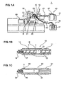
- FIG. 1A is a side view showing an entire structure of a fiber filler reinforced resin injection molding apparatus according to a first embodiment of the present invention
- FIG. 1B is a sectional view showing a cylinder inside of a plasticizing pushing portion
- FIG. 1C is a sectional view showing a structure of a major portion of the cylinder inside of the plasticizing pushing portion.
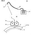
- FIG. 2 is a partially sectional view showing a GF supply unit with a seal structure that prevents a leakage of a foaming agent at the GF supply portion in the first embodiment.
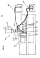
- FIG. 4 is an explanatory diagram showing a schematic structure of a device to compensate a leakage of a physical foaming agent at a GF supply portion of a filler reinforced resin injection molding apparatus according to a third embodiment.
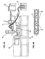
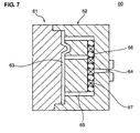
- FIG. 7 is a sectional view of a mold in which the mixing nozzle and a similar agitating device are provided at a hot runner portion.
- the resin collection portion 20 collects the resin composite 5 transmitted from the plasticizing pushing portion 10 in the collector 21 temporarily.
- the resin composite 5 in the collector 21 is controlled so as to be transmitted to a junction portion 33 of the metering injecting portion 30 by a valve 22 that is provided at a downward or downstream end (outlet) of the collector 21.
- the metering injecting portion 30 preferably is configured to be an injection unit in which an injection piston 32 is provided in the cylinder 31, and guides the resin composite 5 in the collector 21 to the junction portion 33 so as to make the reinforcement fiber 3 and the physical foaming agent 4 be mixed with the resin composite 5. Further, after metering of the resin composite for a necessary amount for molding, the resin composite 5 is configured to be injected into a cavity 63 (see FIG. 7 ) of the mold 60 with an opening/closing operation of a valve 35 that is provided at an injecting end 34 (outlet) and an reciprocating movement of the injection piston 32.
- valves 18, 22 and/or 35 that are opened or closed with the on-off operation.
- These valves 18, 22 and/or 35 allow the resin composite 5 to flow out when opening, and when closing, they stop the flow and preferably prevent counterflow of the resin composite 5 as well, ensuring a proper seal function.
- the reinforcement fiber 3 may not be broken or hurt by operations of the valves 18, 22 and/or 35.
- the SCF supply unit 40 guides the (physical or chemical) foaming agent 4 into the fiber filler reinforced resin injection molding apparatus 1, in which the foaming agent 4 is supplied into the cylinder 11 (the resin 2 ) at the foaming-agent supply portion 15 provided at the plasticizing pushing portion 10.
- the SCF supply unit 40 comprises a gas reservoir 41 with a raw gas stored therein, and a pressure-increase control portion 42 to increase a pressure of the raw gas from the gas reservoir 41 to a specified (predetermined or predeterminable) pressure and control a supply amount of the pressure-increased physical foaming agent into the cylinder 11.
- the GF supply unit 50 (as the preferred reinforcement fiber supply unit) supplies the reinforcement fiber 3 (preferably continuous glass fiber 3 in the present embodiment) to the reinforcement-fiber mixing portion 14 of the plasticizing pushing portion 10.
- the GF supply unit 50 comprises, as shown in FIG. 2 , a GF storage portion 51 that stores the reinforcement fiber (preferably the substantially round glass fiber 3) in a coil shape therein with a proper seal, a GF supply portion 53 that is connected to the reinforcement-fiber mixing portion 15, a flexible supply pipe 52 that interconnects the GF storage portion 51 and the GF supply portion 53 and supplies the reinforcement fiber (preferably glass fiber) 3 therein.
- the GF supply portion 53 of the present embodiment comprises a fiber supply roller 54 to supply the reinforcement fiber (preferably glass fiber) 3 with its rotation, and a seal member 55 that can provide proper sealing between side walls of the cylinder 11 (cylinder barrel 11 a), in which the roller 54 is held by the seal member 55 so as to be pushed substantially against a periphery of an opening of the reinforcement-fiber mixing portion 14. Accordingly, the portions 51, 52 and 53 are connected with proper sealing (air- or fluid-tightness), and the inside circumference is properly shut off from an outside atmosphere with the sealing. Thereby, the (physical or chemical) foaming agent 4 and the resin composite 5 containing the foaming agent 4, which have been supplied into the cylinder 11, are prevented from leaking out from the reinforcement-fiber mixing portion 14 (GF supply portion 53, GF supply unit 50).
- the continuous glass fiber 3 is supplied into the cylinder 11 of the plasticizing pushing portion 10 by the roller 54 with its rotation, where the fiber 3 is cut into pieces preferably by a shearing force of the screw 12 rotating in the cylinder 11.
- a length of the fiber pieces preferably can be adjusted by the rotational speed of the screw 12, the relative friction force between the fiber 3 and the roller 54 and/or the supply speed of the fiber 3 by the roller 54.
- the mixing portion 14 of the reinforcement fiber 3 preferably is located downstream of the anti counterflow portion 13 of the screw 12.
- the supply portion 15 of the (physical or chemical) foaming agent 4 preferably is (likewise) located downstream of the anti counterflow portion 13 of the screw 12 and/or upstream of the mixing portion 14 of the reinforcement fiber 3.
- the reinforcement fiber 3 is mixed with resin 2 that has reduced its viscosity with the (physical or chemical) foaming agent 4, so that the mixing and dispersion of the reinforcement fiber 3 can be improved. Also, the mixed fiber 3 is transmitted downward by the (physical or chemical) foaming agent 4, so it may not go upstream.
- the reinforcement fiber 3 is mixed with the resin 2 preferably at the portion (mixing portion 14 ) located downstream of the supply portion of the (physical or chemical) foaming agent 4 (supply portion 15 ). Accordingly, the reinforcement fiber 3 is mixed with resin 2 that has reduced its viscosity with the (physical or chemical) foaming agent 4, so that the mixing and dispersion of the reinforcement fiber 3 in the resin composite 5 can be improved.
- thermoplastic resin preferably is used as the following resin 2, and the following thermoplastic resin may be applied; polyethylene-based resin, polypropylene-based resin, acrylonitrile-butadiene-styrene copolymer (ABS resin), polystyrene-based resin, polycarbonate-based resin, polyethylene terephthalate, polybutylene terephthalate, acrylonitrile-styrene copolymer (AS resin), sybdiotactic polystyrene, polymethyl methacrylate, polyphenylene sulfide, polyether sulfone, polyarylate, polyamide, polyimide, liquid crystal resin, polyphenylene oxide, polyacetal, polyethylene naphthalate, and so on.
- ABS resin acrylonitrile-butadiene-styrene copolymer
- AS resin acrylonitrile-styrene copolymer
- AS resin acrylonitrile-styrene copo
- reinforcement fiber 3 glass fiber, carbon fiber, inorganic whisker, potassium titanate whisker, and so on preferably may be applied.
- the content of the thermoplastic resin 2 with respect to the thermoplastic resin composite 5 is preferably about 20 - about 95 wt%, more preferably about 60 - about 90 wt%. There is a concern of a poor flowing function or a weak mechanical rigidity if the content of the thermoplastic resin 2 is too small. Also, the content of the reinforcement fiber 3 with respect to the thermoplastic resin composite 5 is preferably about 0 - about 50 wt%, more preferably about 10 - about 40 wt%.
- thermoplastic resin composite 5 may be added an additive or changing agent, such as powder fillers, plasticizing agent, stabilizing agent, anti oxidant, ultraviolet-ray absorbent, anti-charging agent, flame retardant, or flame-resistant agent.
- an additive or changing agent such as powder fillers, plasticizing agent, stabilizing agent, anti oxidant, ultraviolet-ray absorbent, anti-charging agent, flame retardant, or flame-resistant agent.
- the physical foaming agent 4 (as the preferred foaming agent) in the present embodiment includes any foaming agent with a pressure lower than the super critical pressure, other than the super critical fluid in the super critical state (Super Critical Fluid: SCF), just excluding a chemical foaming agent that foams with a heat caused by a chemical reaction.
- a super critical fluid is a fluid that is in a state where the temperature and pressure of the fluid exceeds respectively the critical temperature and/or pressure that allow the at least partial coexistence of gas and liquid.
- the reinforcement-fiber mixing portion 14 is located downstream of the foaming-agent supply portion 15. Thereby, since the reinforcement fiber 3 is mixed with the resin 2 to which the foaming agent 4 is supplied, the reinforcement fiber 3 is mixed with resin 2 that has reduced its viscosity with the foaming agent 4. Thus, the mixing and dispersion of the reinforcement fiber 3 in the resin composite 5 can be improved.
- the resin composite 5 collected temporarily in the resin collection portion 20 is transmitted to the metering injecting portion 30, and after metering of the resin composite 5 for the necessary amount for molding, the resin composite 5 is supplied into the cavity 63 of the mold 60 via the metering injecting portion 30. Since this supply (confluence) promotes the mixing and dispersion of the reinforcement fiber 3 in the resin composite 5, the reinforcement fiber 3 can be dispersed uniformly. Thus, the fiber filler reinforced resin molded article with more excellent properties can be provided.
- the resin composite 5 plasticized at the plasticizing pushing portion 10 is supplied directly to the junction portion 33 of the metering injecting portion 30.
- the mixing and dispersion of the reinforcement fiber 3 and the (physical or chemical) foaming agent 4 in the resin composite 5 is attained, and after metering of the resin composite 5 for the necessary amount for molding, the resin composite 5 is injected into the cavity 63 of the mold 60.
- the leakage amount of the foaming agent 4 that has leaked from the reinforcement-fiber mixing portion 14 is detected by the flow-amount detecting device (flow meter 45 ) in the path (SCF guide pipe 44 ), and the foaming agent 4 can be supplemented by the amount corresponding to the leakage amount from the foaming-agent supply portion(s) 15, 15' .
- the necessary amount of the foaming agent 4 in the resin composite 5 can be substantially maintained, and the properties of the resin molded article having the desirable foaming ratio can be improved.
Landscapes
- Engineering & Computer Science (AREA)
- Mechanical Engineering (AREA)
- Injection Moulding Of Plastics Or The Like (AREA)
- Molding Of Porous Articles (AREA)
Description
- The present invention relates to a molding method according to
claim 1 and apparatus according to claim 8 of a fiber filler reinforced foam resin molded article. - A resin molded article that is made from a foam resin material has been recently used widely for the purpose of weight reduction and the like. A molding method of such a foam resin molded article is generally known, in which a super critical fluid (SCF) as a physical foaming agent is previously supplied to a thermoplastic resin, and then the resin is injected into a cavity (a space in a mold) for foaming with a pressure reduction.
- Herein, in order to purse further weight reduction, a resin molded article that is reinforced with a fiber such as a glass fiber to increase strength and rigidity has been also developed. In a molding method of such a fiber filler reinforced foam resin molded article, the resin containing the reinforcement fiber is plasticized and kneaded (molten) in a cylinder of an injection unit by using a screw (a process before injecting into the mold), so that the reinforcement fiber can be mixed well in the resin. Then, the super critical fluid is supplied to the molten resin with pressing to and maintaining a certain pressure, which is followed by injecting the resin into the cavity for foaming with the pressure reduction.
-
US Patent Application Publication No. 2004/0253335 A1 discloses a molding method in which there is provided a gas supply nozzle for supplying the super critical fluid or a foaming agent to a portion just downstream of a ring-shaped check valve that is provided as a pressure-maintaining element at the injection molding screw. Herein, the ring-shaped check valve restricts a flow in an upstream direction, thereby maintaining a downstream pressure of a substance. -
US-A-2003 000 3291 discloses a method according to the preamble ofclaim 1 andUS-A-5 707 571 an apparatus according to the preamble of claim 8. - In a case where a fiber filler reinforced foam resin molded article is made with the conventional molding method disclosed in the above-described publication, there is a problem in that at a plasticizing stage by agitating and kneading the reinforcement fiber and resin, the reinforcement fiber is cut and broken by the screw, so the resin molded article may have poor properties that are worse than desired ones. In particular, when supplying the physical foaming agent, which is made of the super critical fluid or the like, into the cylinder for plasticizing, there is the following problem.
- Namely, in case of using the super critical fluid as the foaming agent, the super critical fluid is supplied into the molten resin in a pressurized state to prevent foaming, the pressure is maintained in the process of injecting the molten resin into the mold, and the pressure is finally reduced (released) in the cavity. Accordingly, the pressure applied to the molten resin in the cylinder is maintained to a high pressure before the injection process. In the process of the spiral-shaped screw transmitting the molten resin to a downstream direction (injection end), the above-described pressure also acts on the upstream side of the supply portion of the super critical fluid, and therefore a force operative to push back the molten resin, resin pellets and reinforcement fiber would be generated. Accordingly, there may be a necessity that the screw has a certain mechanism to prevent the counterflow of the molten resin containing the super critical fluid at a portion that is located upstream of the supply portion of the super critical fluid.
- This kind of anti counterflow mechanism generally comprises a labyrinth structure of resin flow path so as to prevent the upstream-direction pushing back. Herein, in case of applying the above-described structure of anti counterflow mechanism to the screw, there is a problem that the reinforcement fiber mixed with the resin would be cut into pieces and broken when getting though this mechanism (labyrinth structure). Thus, the properties of the fiber filler reinforced foam resin molded article that is made by the molding method with the super critical fluid would deteriorate improperly.
- The above-described problem may not be recognized in the above publication because the resin containing the reinforcement fiber (short glass fiber) is supplied to a portion upstream of the ring-shaped check valve in its embodiment. The ring-shaped check valve changes its position in such a manner that its ring member contacts either one of a seal face and a block face of the screw, thereby allowing the resin to flow in the downstream direction and restricting the pressure from the super critical fluid supplied downstream. Accordingly, although this ring-shaped check valve may have the same problem of breakage of the reinforcement fiber, no countermeasure seems to be applied.
- The present invention has been devised in view of the above-described problem, and an object of the present invention is to provide a molding method and apparatus of a fiber filler reinforced resin molded article that can improve properties, such as strength, rigidity and the like, particularly by preventing the reinforcement fiber from being broken at the anti counterflow portion of the screw.
- This object is solved by the molding method of a fiber filler reinforced resin molded article according to the present invention of
claim 1 and the molding apparatus of a fiber filler reinforced resin molded article according to the present invention of claim 8. Preferred embodiments of the present invention are subject of the dependent claims. - According to the present invention, there is provided a molding method of a fiber filler reinforced resin molded article, according to
claim 1. - Also, according to the present invention, there is provided a molding apparatus of a fiber filler reinforced resin molded article, according to claim 8.
- According to the above molding method or apparatus, since the location of mixing the reinforcement fiber is substantially downstream of the anti counterflow portion, the reinforcement fiber can be prevented from being broken at the anti counterflow portion. Also, the location of supplying the (preferably physical or chemical) foaming agent is substantially downstream of the anti counterflow portion. Herein, the reinforcement-fiber mixing portion and the foaming-agent supply portion may be located at the same location in the flow direction, or either one may be located upstream of the other. In any case, as long as both the portions are located upstream of the anti counterflow portion, the breakage of the reinforcement fiber can be prevented, without making the molding method or apparatus complex. Thus, the fiber filler reinforced resin molded article with improved properties, such as strength, rigidity and the like, can be provided.
- According to an embodiment of the molding method or apparatus of the present invention, the (preferably physical or chemical) foaming agent is a super critical fluid.
- Thereby, since the super critical fluid can be mixed and dispersed uniformly as the (preferably physical or chemical) foaming agent, the molded article having a properly fine foam cell can be provided.
- According to another embodiment of the molding method or apparatus of the present invention, the reinforcement fiber is mixed with the resin in the cylinder at a portion that is located substantially downstream of the above supply portion of the (preferably physical or chemical) foaming agent.
- Thereby, since the reinforcement fiber is mixed substantially downstream of the supply portion of the (preferably physical or chemical) foaming agent, the reinforcement fiber is mixed with the resin that has reduced its viscosity with the (preferably physical or chemical) foaming agent, so that the mixing and dispersion of the reinforcement fiber can be improved.
- According to further another embodiment of the molding method or apparatus of the present invention, the reinforcement fiber is provided independently so as to be mixed with the resin.
- Thereby, since the reinforcement fiber is provided independently from the reinforcement-fiber mixing portion, a seal structure with proper airtightness can be applied at the reinforcement-fiber mixing portion. Accordingly, the (preferably physical or chemical) foaming agent and the plasticized molten resin can be surely prevented from leaking out from the reinforcement-fiber mixing portion.
- According to further another embodiment of the molding method or apparatus of the present invention, the reinforcement fiber is provided in a form of a continuous fiber to the cylinder, and the provided continuous fiber is cut into pieces by the screw, whereby the reinforcement fiber is mixed with the resin in the cylinder.
- Thereby, since the reinforcement fiber is provided in the form of the continuous fiber, a proper fluid- or airtightness at the reinforcement-fiber mixing portion can be improved properly with a simple structure, and the leakage of the (preferably physical or chemical) foaming agent and plasticized molten resin from the reinforcement-fiber mixing portion can be surely prevented.
- According to further another embodiment of the molding method of the present invention, mixing and/or dispersion of the reinforcement fiber in the resin is promoted in a resin flow path from the supply portion of the (preferably physical or chemical) foaming agent to the cavity of the mold. And, according to further another embodiment of the molding apparatus of the present invention, there is provided a mixing-dispersion promoting device to promote mixing and dispersion of the reinforcement fiber in the resin in a resin flow path from the supply portion of the (preferably physical or chemical) foaming agent to the cavity of the mold.
- Thereby, even if the mixing and dispersion of the reinforcement fiber in the resin is insufficient, the promotion of mixing and dispersion of the reinforcement fiber in the path from the mixing portion of the reinforcement fiber to the cavity of the mold can be attained by the mixing-dispersion promoting device. Thus, the reinforcement fiber can be dispersed more uniformly in the plasticized molten resin, and the fiber filler reinforced resin molded article with excellent properties can be provided.
- According to further another embodiment of the molding method or apparatus of the present invention, the resin with the (preferably physical or chemical) foaming agent supplied thereto and the reinforcement fiber mixed therewith is collected temporarily, transmitted to an injection unit, metered for molding, and then supplied to the cavity of the mold via the injection unit.
- Thereby, the molten resin with the (preferably physical or chemical) foaming agent and reinforcement fiber, which is collected temporarily in the collection portion, is transmitted to the injection unit, and after metering of the resin for the necessary amount for molding, the resin is supplied into the cavity of the mold via the injection unit. Thus, since this supply (confluence) promotes the mixing and dispersion of the reinforcement fiber in the molten resin, the reinforcement fiber can be dispersed uniformly, and the fiber filler reinforced resin molded article with more excellent properties can be provided.
- According to further another embodiment of the molding apparatus of the present invention, there is provided a seal device to seal an inside from an outside of the cylinder at the reinforcement-fiber mixing portion.
- Thereby, since the reinforcement-fiber mixing portion is sealed by the seal device, the leakage of the (preferably physical or chemical) foaming agent and plasticized molten resin from the reinforcement-fiber mixing portion can be surely prevented.
- According to further another embodiment of the molding apparatus of the present invention, there is provided a flow-amount detecting device that is provided in a leakage path of the (preferably physical or chemical) foaming agent leaking from the reinforcement-fiber mixing portion and detects an amount of leakage of the (preferably physical or chemical) foaming agent, and the (preferably physical or chemical) foaming agent is configured to be supplemented from the foaming-agent supply portion substantially according to the leakage amount thereof detected by the flow-amount detecting device.
- Thereby, the amount of leakage of the (preferably physical or chemical) foaming agent is detected by the flow-amount detecting device provided in the leakage path of the (preferably physical or chemical) foaming agent leaking from the reinforcement-fiber mixing portion, and the amount of the (preferably physical or chemical) foaming agent corresponding to the amount that has leaked is supplemented from the foaming-agent supply portion. Thus, the necessary amount of the (preferably physical or chemical) foaming agent in the resin composite can be maintained, and thereby the properties of the resin molded article having a desirable foaming ratio can be improved.
- Other features, aspects, and advantages of the present invention will become apparent from the following description which refers to the accompanying drawings.
-
FIG. 1A is a side view showing an entire structure of a fiber filler reinforced resin injection molding apparatus according to a first embodiment of the present invention,FIG. 1B is a sectional view showing a cylinder inside of a plasticizing pushing portion, andFIG. 1C is a sectional view showing a structure of a major portion of the cylinder inside of the plasticizing pushing portion. -
FIG. 2 is a partially sectional view showing a GF supply unit with a seal structure that prevents a leakage of a foaming agent at the GF supply portion in the first embodiment. -
FIG. 3 is a side view showing an entire structure of a fiber filler reinforced resin injection molding apparatus according to a second embodiment. -
FIG. 4 is an explanatory diagram showing a schematic structure of a device to compensate a leakage of a physical foaming agent at a GF supply portion of a filler reinforced resin injection molding apparatus according to a third embodiment. -
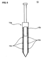
FIG. 5A a view showing an attachment state of a mixing nozzle, andFIG. 5B is a sectional view of a major portion of the mixing nozzle. -
FIG. 6A is a sectional view showing a cylinder inside of a metering injecting portion with a supersonic oscillator (or an electromagnetic-wave oscillator) of a vibration adding device, andFIG. 6B is a sectional view showing an attachment state of an agitating plate in the cylinder inside of the metering injecting portion. -
FIG. 7 is a sectional view of a mold in which the mixing nozzle and a similar agitating device are provided at a hot runner portion. -
FIG. 8 is a side view of a foaming-agent supply portion in which a porous member is disposed at an inside wall of a supply nozzle. -
FIG. 9 is a side view showing a seal structure with a resilient member as a modified embodiment. - Hereinafter, a molding method and apparatus of a fiber filler reinforced resin molded article of the present invention will be described specifically. It should be understood that even though embodiments are separately described, single features thereof may be combined to additional embodiments.
- An entire structure of a fiber filler reinforced resin injection molding apparatus according to a first preferred embodiment of the present invention is shown in
FIG. 1 . The fiber filler reinforced resininjection molding apparatus 1 comprises a plasticizing orplasticating pushing portion 10, aresin collection portion 20, ametering injecting portion 30, a super critical fluid (SCF)supply unit 40, a glass fiber (GF) supply unit 50 (as a preferred reinforcing fiber supply unit), and amold 60. - The
plasticizing pushing portion 10 has a screw orworm screw 12 in amaterial supply cylinder 11, and agitates, kneads and/or conveys aresin 2 which is provided from ahopper 16 with a rotation of thescrew 12 for plasticizing (melting). And, at least onereinforcement fiber 3, which is supplied from theGF supply unit 50 at a reinforcement-fiber mixing portion 14, and a physical orchemical foaming agent 4, which is supplied from theSCF supply unit 40 at a foaming-agent supply portion 15, are mixed with the plasticized molten resin or while the resin is being plasticized. Then, the plasticized molten resin containing the reinforcement fiber 3 (and the physical or chemical foaming agent 4) (hereinafter, referred to as resin composite 5) is pushed out (transmitted or conveyed) to aresin collection portion 20, where the resin is collected temporarily in acollector 21. In the present embodiment, theplasticizing pushing portion 10 preferably is not constituted as an injection unit, and has a capability to push out and transmit the plasticizedresin composite 5 to theresin collection portion 30. An on-offvalve 18 is provided at a pushing end (outlet) 17 of theplasticizing pushing portion 10. - The
screw 12 provided inside thecylinder 11 preferably includes ananti counterflow portion 13. Theanti counterflow portion 13 may be configured, for example, to have a labyrinthine structure as described above, or a ring-member position changing mechanism. Positional relationships among thecounterflow portion 13, the reinforcement-fiber mixing portion 14, and the foaming-agent supply portion 15 will be described specifically below. - The
resin collection portion 20 collects theresin composite 5 transmitted from theplasticizing pushing portion 10 in thecollector 21 temporarily. Theresin composite 5 in thecollector 21 is controlled so as to be transmitted to ajunction portion 33 of themetering injecting portion 30 by a valve 22 that is provided at a downward or downstream end (outlet) of thecollector 21. - The
metering injecting portion 30 preferably is configured to be an injection unit in which aninjection piston 32 is provided in thecylinder 31, and guides theresin composite 5 in thecollector 21 to thejunction portion 33 so as to make thereinforcement fiber 3 and thephysical foaming agent 4 be mixed with theresin composite 5. Further, after metering of the resin composite for a necessary amount for molding, theresin composite 5 is configured to be injected into a cavity 63 (seeFIG. 7 ) of themold 60 with an opening/closing operation of avalve 35 that is provided at an injecting end 34 (outlet) and an reciprocating movement of theinjection piston 32. - As described above, at the lower ends (outlets) of the
plasticizing pushing portion 10,resin collection portion 20, and/ormetering injecting portion 30 are provided thevalves 18, 22 and/or 35 that are opened or closed with the on-off operation. Thesevalves 18, 22 and/or 35 allow theresin composite 5 to flow out when opening, and when closing, they stop the flow and preferably prevent counterflow of theresin composite 5 as well, ensuring a proper seal function. Herein, since thesevalves 18, 22 and/or 35 are just operated to open and close, thereinforcement fiber 3 may not be broken or hurt by operations of thevalves 18, 22 and/or 35. - The
SCF supply unit 40 guides the (physical or chemical) foamingagent 4 into the fiber filler reinforced resininjection molding apparatus 1, in which thefoaming agent 4 is supplied into the cylinder 11 (the resin 2) at the foaming-agent supply portion 15 provided at theplasticizing pushing portion 10. TheSCF supply unit 40 comprises agas reservoir 41 with a raw gas stored therein, and a pressure-increase control portion 42 to increase a pressure of the raw gas from thegas reservoir 41 to a specified (predetermined or predeterminable) pressure and control a supply amount of the pressure-increased physical foaming agent into thecylinder 11. - The GF supply unit 50 (as the preferred reinforcement fiber supply unit) supplies the reinforcement fiber 3 (preferably
continuous glass fiber 3 in the present embodiment) to the reinforcement-fiber mixing portion 14 of theplasticizing pushing portion 10. TheGF supply unit 50 comprises, as shown inFIG. 2 , aGF storage portion 51 that stores the reinforcement fiber (preferably the substantially round glass fiber 3) in a coil shape therein with a proper seal, aGF supply portion 53 that is connected to the reinforcement-fiber mixing portion 15, aflexible supply pipe 52 that interconnects theGF storage portion 51 and theGF supply portion 53 and supplies the reinforcement fiber (preferably glass fiber) 3 therein. TheGF supply portion 53 of the present embodiment comprises afiber supply roller 54 to supply the reinforcement fiber (preferably glass fiber) 3 with its rotation, and aseal member 55 that can provide proper sealing between side walls of the cylinder 11 (cylinder barrel 11a), in which theroller 54 is held by theseal member 55 so as to be pushed substantially against a periphery of an opening of the reinforcement-fiber mixing portion 14. Accordingly, theportions agent 4 and theresin composite 5 containing thefoaming agent 4, which have been supplied into thecylinder 11, are prevented from leaking out from the reinforcement-fiber mixing portion 14 (GF supply portion 53, GF supply unit 50). - Then, preferably the
continuous glass fiber 3 is supplied into thecylinder 11 of theplasticizing pushing portion 10 by theroller 54 with its rotation, where thefiber 3 is cut into pieces preferably by a shearing force of thescrew 12 rotating in thecylinder 11. A length of the fiber pieces preferably can be adjusted by the rotational speed of thescrew 12, the relative friction force between thefiber 3 and theroller 54 and/or the supply speed of thefiber 3 by theroller 54. - According to the present embodiment, the mixing
portion 14 of thereinforcement fiber 3 preferably is located downstream of theanti counterflow portion 13 of thescrew 12. Also, thesupply portion 15 of the (physical or chemical) foamingagent 4 preferably is (likewise) located downstream of theanti counterflow portion 13 of thescrew 12 and/or upstream of the mixingportion 14 of thereinforcement fiber 3. Thus, by the location of the mixingportion 14 of thereinforcement fiber 3 downstream of theanti counterflow portion 13, thereinforcement fiber 3 can be advantageously prevented from being broken at theanti counterflow portion 13. And, by the location of thesupply portion 15 of the (physical or chemical) foamingagent 4 upstream the mixingportion 14 of thereinforcement fiber 3, thereinforcement fiber 3 is mixed withresin 2 that has reduced its viscosity with the (physical or chemical) foamingagent 4, so that the mixing and dispersion of thereinforcement fiber 3 can be improved. Also, themixed fiber 3 is transmitted downward by the (physical or chemical) foamingagent 4, so it may not go upstream. - Further, according to the present embodiment, the
reinforcement fiber 3 is mixed with theresin 2 preferably at the portion (mixing portion 14) located downstream of the supply portion of the (physical or chemical) foaming agent 4 (supply portion 15). Accordingly, thereinforcement fiber 3 is mixed withresin 2 that has reduced its viscosity with the (physical or chemical) foamingagent 4, so that the mixing and dispersion of thereinforcement fiber 3 in theresin composite 5 can be improved. - In the present embodiment, a thermoplastic resin preferably is used as the following
resin 2, and the following thermoplastic resin may be applied; polyethylene-based resin, polypropylene-based resin, acrylonitrile-butadiene-styrene copolymer (ABS resin), polystyrene-based resin, polycarbonate-based resin, polyethylene terephthalate, polybutylene terephthalate, acrylonitrile-styrene copolymer (AS resin), sybdiotactic polystyrene, polymethyl methacrylate, polyphenylene sulfide, polyether sulfone, polyarylate, polyamide, polyimide, liquid crystal resin, polyphenylene oxide, polyacetal, polyethylene naphthalate, and so on. Especially, the polypropylene-based resin, polystyrene-based resin, polycarbonate-based resin, sybdiotactic polystyrene, polyphenylene sulfide are preferable, and polypropylene-based resin are more preferable. Also, polymer blend is applicable as the thermoplastic resin. - Also, as the
reinforcement fiber 3, glass fiber, carbon fiber, inorganic whisker, potassium titanate whisker, and so on preferably may be applied. - The content of the
thermoplastic resin 2 with respect to thethermoplastic resin composite 5 is preferably about 20 - about 95 wt%, more preferably about 60 - about 90 wt%. There is a concern of a poor flowing function or a weak mechanical rigidity if the content of thethermoplastic resin 2 is too small. Also, the content of thereinforcement fiber 3 with respect to thethermoplastic resin composite 5 is preferably about 0 - about 50 wt%, more preferably about 10 - about 40 wt%. - Further, to the above-described
thermoplastic resin composite 5 may be added an additive or changing agent, such as powder fillers, plasticizing agent, stabilizing agent, anti oxidant, ultraviolet-ray absorbent, anti-charging agent, flame retardant, or flame-resistant agent. - The physical foaming agent 4 (as the preferred foaming agent) in the present embodiment includes any foaming agent with a pressure lower than the super critical pressure, other than the super critical fluid in the super critical state (Super Critical Fluid: SCF), just excluding a chemical foaming agent that foams with a heat caused by a chemical reaction. A super critical fluid is a fluid that is in a state where the temperature and pressure of the fluid exceeds respectively the critical temperature and/or pressure that allow the at least partial coexistence of gas and liquid.
- Although any type of (physical or chemical) foaming
agent 4 may be applied in the present embodiment as long as it can be molten in thethermoplastic resin composite 5 and is an inert gas regardless of being in the super critical state, the super critical fluid of carbon dioxide, nitrogen or composite gas of these is preferable from viewpoints of safety, costs and the like. And, when thephysical foaming agent 4 of these gas is applied, thefoaming agent 4 can be mixed and dispersed well, thereby providing the fiber filler reinforced resin molded article (product) having a properly fine foam cell and a further improved properties. - The application of the super critical fluid of carbon dioxide may be more preferable because of little damage against the global environment. The critical temperature of the carbon dioxide is 31. 3 °C and the critical pressure thereof is 7.4 MPa, and the critical temperature of the nitrogen is - 147 °C and the critical pressure thereof is 3.4 MPa. Accordingly, the super critical state of these can be easily maintained by heating and pressuring (herein, heating may not be necessary for the nitrogen). Also, since the super critical fluid of the carbon dioxide or nitrogen functions as a plasticizing agent, the flowing of the resin can be improved, thereby providing the injection molding of the
resin composite 5 containing thereinforcement fiber 3 with better flowing properties. - It is preferable from viewpoints of ensuring a sufficient supply speed that the pressure at a time the (physical or chemical) foaming
agent 4 is supplied to thethermoplastic resin composite 5 be set to about 15 MPa or more, further preferably about 20 MPa or more. The supply amount of thephysical foaming agent 4 depends on the kind thereof, but it is preferable that the supply amount with respect to about 100 wt% of thethermoplastic resin composite 5 be set to about 0.1 - about 20 wt%, further preferably about 0.5 - about 10 wt%. Accordingly, the properly fine foam cell can be provided while advantageously avoiding that the foam cell may become too large and an appearance of the molded article may deteriorate. - In the present embodiment, the
mold 60 comprises astationary mold 61 and amovable mold 62, which preferably at least partly are made from metal or steel material such as carbon steel, aluminum alloy, or copper alloy. Thecavity 63 is formed by thesemolds hot runner portion 66 is provided in a flow path of themolten resin composite 5 from an injection supply hole 64 (nozzle) to agate 65. - As described above, according to the present embodiment, since the location of mixing the reinforcement fiber 3 (reinforcement-fiber mixing portion 14) is downstream of the
anti counterflow portion 13, thereinforcement fiber 3 can be prevented from being broken at theanti counterflow portion 13. Also, the location of supplying the physical foaming agent 4 (foaming-agent supply portion 15) is downstream of theanti counterflow portion 13. Herein, the reinforcement-fiber mixing portion 14 and the foaming-agent supply portion 15 may be located at the substantially same location in the flow direction, or either one may be located upstream of the other. In any case, as long as both theportions anti counterflow portion 13, the breakage of thereinforcement fiber 3 can be prevented, without making the molding method or apparatus complex. Thus, the fiber filler reinforced resin molded article with improved properties, such as strength, rigidity and the like, can be provided. - According to the present embodiment, the reinforcement-
fiber mixing portion 14 is located downstream of the foaming-agent supply portion 15. Thereby, since thereinforcement fiber 3 is mixed with theresin 2 to which thefoaming agent 4 is supplied, thereinforcement fiber 3 is mixed withresin 2 that has reduced its viscosity with thefoaming agent 4. Thus, the mixing and dispersion of thereinforcement fiber 3 in theresin composite 5 can be improved. - Further, since the
reinforcement fiber 3 is provided independently from the reinforcement-fiber mixing portion 14, the seal structure with proper fluid- or air-tightness can be applied at the reinforcement-fiber mixing portion 14. Thereby, thefoaming agent 4 and theresin composite 5 can be surely prevented from leaking out from the reinforcement-fiber mixing portion 14. Also, since thereinforcement fiber 3 preferably is provided in the form of the continuous fiber, the proper fluid- or air-tightness can be improved properly with a simple structure. - The
resin composite 5 collected temporarily in theresin collection portion 20 is transmitted to themetering injecting portion 30, and after metering of theresin composite 5 for the necessary amount for molding, theresin composite 5 is supplied into thecavity 63 of themold 60 via themetering injecting portion 30. Since this supply (confluence) promotes the mixing and dispersion of thereinforcement fiber 3 in theresin composite 5, thereinforcement fiber 3 can be dispersed uniformly. Thus, the fiber filler reinforced resin molded article with more excellent properties can be provided. - Accordingly, in a molding method of a fiber filler reinforced resin molded article, in which a
reinforcement fiber 3 and aresin 2 are plasticized and kneaded in amaterial supply cylinder 11 including ascrew 12 with ananti counterflow portion 13, and theresin 5 with thereinforcement fiber 3 at least partly mixed therewith is injected into a cavity of amold 60, thereinforcement fiber 3 is mixed with the resin in thecylinder 11 at a portion downstream of theanti counterflow portion 13 of thescrew 12, and a (physical or chemical) foamingagent 4 is supplied into thecylinder 11 at a portion downstream of theanti counterflow portion 13. Accordingly, there can be provided a molding method or apparatus of a fiber filler reinforced resin molded article that can improve properties by preventing the reinforcement fiber from being broken. - An entire structure of a fiber filler reinforced resin injection molding apparatus according to a second preferred embodiment of the present invention is shown in
FIG. 3 . The fiber filler reinforced resininjection molding apparatus 1A is different from theapparatus 1 of the first embodiment in having noresin collection portion 20. Theapparatus 1A has the similar or substantially same components as theapparatus 1 except the following portion. The similar or substantially same components of theapparatus 1A are denoted by the same reference characters as those of theapparatus 1, whose descriptions will be omitted. - In the present embodiment, the
resin composite 5 plasticized at theplasticizing pushing portion 10 is supplied directly to thejunction portion 33 of themetering injecting portion 30. At thejunction portion 33, the mixing and dispersion of thereinforcement fiber 3 and the (physical or chemical) foamingagent 4 in theresin composite 5 is attained, and after metering of theresin composite 5 for the necessary amount for molding, theresin composite 5 is injected into thecavity 63 of themold 60. - In the second embodiment, like the first embodiment, the foaming-
agent supply portion 15 preferably is located downstream of theanti counterflow portion 13, and the reinforcement-fiber mixing portion 14 is located downstream of the foaming-agent supply portion 15. Accordingly, thereinforcement fiber 3 can be prevented from being broken at theanti counterflow portion 13, and thereinforcement fiber 3 can be mixed and/or dispersed properly in theresin composite 5. Thus, the fiber filler reinforced resin molded article with the improved properties, such as strength, rigidity and the like, can be provided. - In the above-described first embodiment, the
seal member 55 is provided at theGF supply portion 53 to prevent the (physical or chemical) foamingagent 4 and theresin composite 5 from leaking out of the reinforcement-fiber mixing portion 14 (GF supply unit 50). There may be preferably provided a compensating means for compensating thephysical foaming agent 4 according to the amount of leakage of theagent 4 instead. - A schematic structure of a plasticizing pushing portion equipped with a leakage compensating device of the (physical or chemical) foaming agent is shown in
FIG. 4 . Thisplasticizing pushing portion 10, which may be applied to theinjection molding apparatus agent supply potion 15 preferably located downstream of theanti counterflow portion 13 and/or the reinforcement-fiber mixing portion 14 preferably located downstream of the foaming-agent supply potion 15. To the foaming-agent supply potion 15 is coupled asupply pipe 43 to supply the (physical or chemical) foamingagent 5 from theSCF supply unit 40. To the reinforcement-fiber mixing portion 14 is coupled abuffer tank 56, and a branch pipe 57 (provided near the supply pipe 52) to supply thereinforcement fiber 3 from theGF supply unit 50 is attached to a cylindricalside wall face 56a of thebuffer tank 56. To an upperend wall face 56b of thebuffer tank 56 is connected aSCF guide pipe 44 to guide thefoaming agent 4 that has leaked to an outside environment or theSCF supply unit 40. And, a flow meter 45 (flow-amount detecting device) is disposed in theSCF guide pipe 44. Theflow meter 45 preferably detects the leakage amount of thefoaming agent 4. Information of this leakage amount is fed back to theSCF supply unit 40, which operates to supply the substantially same amount of thefoaming agent 4 as the leakage amount into thecylinder 11 through the foaming-agent supply portion 15. Instead, a second foaming-agent supply portion 15' (not illustrated) may be provided preferably downstream of the reinforcement-fiber mixing portion 14, and the substantially same leakage amount of thephysical foaming agent 4 may be supplied again from theSCF supply unit 40 into thecylinder 11 via this second foaming-agent supply portion 15'. - Thus, the amount of the (physical or chemical) foaming
agent 4 that substantially corresponds to the amount that has leaked can be supplemented from the foaming-agent supply portion 15, 15'. The necessary amount of thefoaming agent 4 in theresin composite 5 can be maintained, and thereby the properties of the resin molded article having a desirable foaming ratio can be improved. Herein, the above-described necessary amount and the desirable foaming ratio should be properly decided in designing the resin molded article. Herein, aporous member 58 preferably is provided at an inside face of the upperend wall face 56b and an inside face of the attaching portion of thebranch pipe 57 of thebuffer tank 56. Thisporous member 58 shuts the flow of theresin composite 5 with thefoaming agent 4, thereby preventing theresin composite 5 from leaking further. - According to the third embodiment, the leakage amount of the
foaming agent 4 that has leaked from the reinforcement-fiber mixing portion 14 is detected by the flow-amount detecting device (flow meter 45) in the path (SCF guide pipe 44), and thefoaming agent 4 can be supplemented by the amount corresponding to the leakage amount from the foaming-agent supply portion(s) 15, 15'. Thereby, the necessary amount of thefoaming agent 4 in theresin composite 5 can be substantially maintained, and the properties of the resin molded article having the desirable foaming ratio can be improved. - The above-described embodiments are just examples, and the present invention should not be limited to these. Any modifications can be applied within the scope of a sprit of the present invention.
- Hereinafter, some modifications of the above-described embodiments will be described.
- 1) Although the
supply portion 15 of the (physical or chemical) foamingagent 4 and the mixingportion 14 of thereinforcement fiber 3 preferably are located downstream of theanti counterflow portion 13 of thescrew 12 in this order in the first, second and third embodiments, thesupply portion 14 of thereinforcement fiber 3 may be located upstream of thesupply portion 15 of thephysical foaming agent 4, or theseportions portions anti counterflow portion 13. - 2) Although the
reinforcement fiber 3 in the form of the continuous fiber is supplied from theGF supply unit 50 and independently mixed with the resin in thecylinder 11 at the mixingportion 14 in the first, second and third embodiments, theresin 2 containing thereinforcement fiber 3 with a previously-cut specified (predetermined or predeterminable) length(s) may be supplied from a reinforcement-fiber/resin supply portion that is located downstream of theanti counterflow portion 13. Herein, since there is a concern of leakage of the (physical or chemical) foamingagent 4 andresin composite 5 due to the pressure increasing according to the supply of thephysical foaming agent 4 at the reinforcement-fiber/resin supply portion, it may be necessary to provide the seal structure described above. Herein, in the case where the fiber in the form of the continuous fiber is supplied like the above embodiment, the seal structure at the mixingportion 14 of thereinforcement fiber 3 can be formed easily. Accordingly, the above-described structure may be preferable. - 3) In the first, second and third embodiments, the
reinforcement fiber 3 supplied from the mixingportion 14 of theplasticizing pushing portion 10 is mixed with theresin composite 5 along with thephysical foaming agent 4 in the area from theportion 14 to thevalve 18 at the pushing end (outlet) 17, and the plasticizedresin composite 5 is received from theresin collection portion 20 or theplasticizing pushing portion 10 at around the injecting end 34 (outlet) of themetering injecting portion 30, and the mixing and dispersion of thereinforcement fiber 3 and thefoaming agent 4 in theresin composite 5 is attained using mixing/dispersion effects preferably by flowing. Herein, however, there is a concern of an insufficiency in this mixing and/or dispersion. Namely, a distance between the reinforcement-fiber mixing portion 14 and thevalve 18 at the pushing end (outlet) 17 is relatively short because of the location of the mixingportion 14 downstream of theanti counterflow portion 13, and thereby the mixing and dispersion of thereinforcement fiber 3 and thefoaming agent 4 with theresin composite 5 might become insufficient.
Accordingly, it is preferable, as shown inFIG. 5A , that theresin composite 5 be injected into themold 60 from themetering injecting portion 30 via a mixingnozzle 70 in the above-described embodiments. This mixingnozzle 70 is configured such that elements A72 that are made of flat plates respectively by twisting (particularly clockwise) by about 180 degrees spirally and other elements B73 that are made of substantially flat plates respectively by twisting (particularly counterclockwise) by about 180 degrees spirally are disposed one after the other in an axis direction. Thus, theresin composite 5 is twisted (clockwise and counterclockwise) repeatedly when proceeding in the mixingnozzle 70. Thereby, the mixing and dispersion of thereinforcement fiber 3 and the (physical or chemical) foamingagent 4 can be promoted.
Accordingly, even if the mixing and dispersion of thereinforcement fiber 3 in theresin composite 5 is insufficient (or there is such a concern), the promotion of mixing and dispersion of thereinforcement fiber 3 in the path from the mixing location (mixing portion 14) of thereinforcement fiber 3 to thecavity 63 of themold 60 can be attained by the mixing-dispersion promoting device like the mixingnozzle 70. Thus, thereinforcement fiber 3 can be dispersed more uniformly in theresin composite 5, and the fiber filler reinforced resin molded article with excellent properties can be provided.
Herein, the mixing-dispersion promoting device is not limited to the above-describedmixing nozzle 70. The internal structure of the mixingnozzle 70 is not limited to the above one, but any modifications may be applied as long as theresin composite 5 can be agitated well in the resin flowing path and thereby the mixing and dispersion of thereinforcement fiber 3 and (physical or chemical) foamingagent 4 can be promoted. As modifications of the mixingnozzle 70, the following alternatives shown in 4) - 6) may be applied. - 4) Although the mixing and dispersion of the
reinforcement fiber 3 and the (physical or chemical) foamingagent 4 in theresin composite 5 is attained when these are received at themetering injecting portion 30 in the first, second and third embodiments, there is not provided any particular promoting mechanism to promote the mixing and dispersion. Herein, there may be provided a vibration adding device for promoting the mixing and dispersion of thereinforcement fiber 3 andphysical foaming agent 4 by actively adding vibrations to theresin composite 5.
For example, a mechanical-vibration adding device with at least onesupersonic oscillator 36A (vibrator device) and/or at least one heating-vibration adding device with an electromagnetic-wave vibrator 36B may be applied as the vibration adding device. In case of using a supersonic vibration, as shown inFIG. 6A , thesupersonic oscillator 36A is attached to the side wall of the cylinder 31 (cylinder barrel outer face) of themetering injecting portion 30. Thesupersonic oscillator 36A vibrates by receiving a supersonic voltage from a supersonic vibrator, not illustrated, so the vibration (agitating force) can be added to theresin composite 5 in thecylinder 31. An attaching portion of thesupersonic oscillator 36A is not limited to the above portion. In case of using the electromagnetic-wave vibration adding device, an attachment of the electromagnetic-wave vibrator 36B is the same as above.
Thus, the vibration is added to theresin composite 5 with the device such as thesupersonic oscillator 36A and/or electromagnetic-wave vibrator 36B, so the mixing and dispersion of thereinforcement fiber 3 andphysical foaming agent 4 in theresin composite 5 can be promoted.
A type of device that can add a flowing force to the resin and thereby agitate it may be applied as the vibration adding device as well. As shown inFIG. 6B , an agitatingplate 37 having plural throughholes 37a preferably is disposed in a space that is located on a side of thejunction portion 33 before theinjection piston 32 in thecylinder 31 of themetering injecting portion 30. This agitatingplate 37 is operated so as to move back and force (reciprocate) in a state where the location of theinjection piston 32 is fixed. Thereby, theresin composite 5 is made get through theseholes 37a according to the back-and-forth movement of the agitating plate 37 (generating a turbulence), so the mixing and dispersion of thereinforcement fiber 3 and foamingagent 4 in theresin composite 5 can be promoted. When the injection is conducted, both theinjection piston 32 and the agitatingplate 37 are moved forward to inject theresin composite 5 into themold 60.
Herein, when the injection is conducted, the agitatingplate 37 is moved forward along with theinjection piston 32 in a state where it is fixed to thepiston 32, or previously moved forward before thepiston 32 is moved forward, so that the agitatingplate 37 can be prevented from interfering with the movement of theinjection piston 32 at the injection process. The shape or the number of the throughholes 37a of the agitating plate 36 should not be limited to an illustrated circular shape or four. Also, something like the above-describedelements 72, 73 (about 180-degree clockwise and counterclockwise twisted plates) applied to the mixingnozzle 70 may be provided at theholes 37a, or theholes 37a may be formed to be of a spiral shape like theseelements plate 37 can be enhanced.
Further, any type of agitating device other than the above-describedplate 37, which can add the flowing force to theresin composite 5 with a reciprocating drive or a rotating drive and thereby agitate it, may be applied. For example, a propeller type of member with agitating wings may be rotated, or a plate member with circular holes having agitating wings therein may be reciprocated. - 5) Although there is not provided a particular mechanism to promote the mixing and/or dispersion of the
reinforcement fiber 3 and (physical or chemical) foamingagent 4 at themold 60 in the first, second and third embodiments, a mixingportion 67 that has a kneading and/or agitating function with the similar or substantially same structure as the above-describedmixing nozzle 70 may be provided in the flow path (e.g., hot runner 66) of themolten resin composite 5 in themold 60 as shown inFIG. 7 . Thereby, the mixing and dispersion of thereinforcement fiber 3 andphysical foaming agent 4 can be promoted before theresin composite 5 flows into thecavity 63 of themold 60. - 6) Although there is not provided a particular mechanism to promote the mixing and/or dispersion of the (physical or chemical) foaming
agent 4 at the foaming-agent supply portion 15 of theplasticizing pushing portion 10 in the first, second and third embodiments, aporous structure 15b (e.g., a metal porous member) preferably may be disposed at an inner wall face of theinjection nozzle 15a as shown inFIG. 8 . Thereby, the (physical or chemical) foamingagent 4 supplied fromsupply holes 15c is introduced into theresin composite 5 with an increased contacting face, so a prompt dispersion of thefoaming agent 4 into the resin composite can be attained, thereby promoting the mixing and/or dispersion. - 7) Although there is provided the seal structure for sealing an entire part of the
GF supply unit 50 in which theseal member 55 holding the fiber-supply roller 54 is pushed against thecylinder barrel 11a (around the opening of the reinforcement-fiber supply portion 14) in the first embodiment, aresilient member 59 with a rubber resiliency may be applied for sealing. For example, as shown inFIG. 9 , a cork-shaped rubber orresilient member 59 with a center throughhole 59a (with its minimum inner diameter smaller than the diameter of the glass fiber 3) is pushed against thecylinder barrel 11a, in which thereinforcement fiber 3 is supplied through thecenter hole 59a, so the seal structure with proper fluid- or air-tightness can be provided. Herein, a pushing face of theresilient member 59 against thecylinder barrel 11a is not limited to a flat one that is illustrated in this figure, but it may have a projection in an O-ring shape. Thus, the seal structure (resilient member 59) is applied locally at the GF supply portion 53 (reinforcement-fiber mixing portion 14), which may provide the simple seal structure and reduce manufacturing costs properly.
Claims (15)
- A molding method of a fiber filler reinforced resin molded article, in which a reinforcement fiber (3) and a resin (2) are plasticized and kneaded in a material supply cylinder (11) including a screw (12) with an anti counterflow portion (13), and the plasticized resin (5) with the reinforcement fiber (3) mixed therewith is injected into a cavity (63) of a mold (60),
wherein the reinforcement fiber (3) is mixed with the resin (2) in the cylinder (11) and a foaming agent (4) is supplied into the cylinder (11) at a portion (15) substantially downstream of the anti counterflow portion (13) of the screw (12), characterised by, that the reinforcement fiber is mixed with the resin (2) in the cylinder (11) and at a portion (14) downstream of the anti counterflow portion (13) of the screw (12), and wherein the amount of leakage of the foaming agent (4) is detected by a flow-amount detecting device (45) provided in the leakage path of the foaming agent (4) leaking from the reinforcement-fiber mixing portion (14), and the amount of the foaming agent (4) corresponding to the amount that has leaked is supplemented from the foaming-agent supply portion (15). - The molding method of a fiber filler reinforced resin molded article of claim 1, wherein the foaming agent (4) is a super critical fluid.
- The molding method of a fiber filler reinforced resin molded article of claim 1 or 2, wherein the reinforcement fiber (3) is mixed with the resin (2) in the cylinder (11) at a portion (14) that is located substantially downstream of said supply portion (15) of the foaming agent (4).
- The molding method of a fiber filler reinforced resin molded article of any one of the preceding claims, wherein the reinforcement fiber (3) is provided independently so as to be mixed with the resin (2).
- The molding method of a fiber filler reinforced resin molded article of claim 4, wherein the reinforcement fiber (3) is provided in a form of a continuous fiber to the cylinder (11), and the provided continuous fiber (3) is cut into pieces by the screw (12), whereby the reinforcement fiber (3) is mixed with the resin (2) in the cylinder (11).
- The molding method of a fiber filler reinforced resin molded article of any one of the preceding claims, wherein mixing and dispersion of the reinforcement fiber (3) in the resin (5) is promoted in a resin flow path from the supply portion (15) of the foaming agent (4) to the cavity (63) of the mold (60).
- The molding method of a fiber filler reinforced resin molded article of any one of the preceding claims, wherein the resin (5) with the foaming agent (4) supplied thereto and the reinforcement fiber (3) mixed therewith is collected temporarily, transmitted to an injection unit (30), metered for molding, and then supplied to the cavity (63) of the mold (60) via the injection unit (30).
- A molding apparatus (1; 1A) of a fiber filler reinforced resin molded article, in which a reinforcement fiber (3) and a resin (2) are plasticized and kneaded in a material supply cylinder (11) including a screw (12) with an anti counterflow portion (12), and the plasticized resin (5) with the reinforcement fiber (3) mixed therewith is injected into a cavity (63) of a mold (60), the molding apparatus (1; 1A) comprising:a reinforcement-fiber mixing portion (14) where the reinforcement fiber (3) is mixed with the resin (2) in the cylinder (11), the mixing portion (14) being downstream of the anti counterflow portion (13) of the screw (12); anda foaming-agent supply portion (15) where a foaming agent (4) is supplied into the cylinder (11), the supply portion (15) being substantially downstream of the anti counterflow portion (13) of the screw (12), characterised by, thatthere is provided a flow-amount detecting device (45) that is provided in a leakage path of the foaming agent (4) leaking from the reinforcement-fiber mixing portion (14) and detects an amount of leakage of the foaming agent (4), and the foaming agent (4) is configured to be supplemented from the foaming-agent supply portion (15) substantially according to the leakage amount thereof detected by the flow-amount detecting device (45).
- The molding apparatus (1; 1A) of a fiber filler reinforced resin molded article of claim 8, wherein the foaming agent (4) is a super critical fluid.
- The molding apparatus (1; 1A) of a fiber filler reinforced resin molded article of claim 8 or 9, wherein the reinforcement fiber (3) is mixed with the resin (2) in the cylinder (11) at a portion (14) that is located downstream of said supply portion (15) of the foaming agent (4).
- The molding apparatus (1; 1A) of a fiber filler reinforced resin molded article of any one of claims 8 through 10, wherein the reinforcement fiber (3) is provided independently so as to be mixed with the resin (2).
- The molding apparatus (1; 1A) of a fiber filler reinforced resin molded article of claim 11, wherein the reinforcement fiber (3) is provided in a form of a continuous fiber to the cylinder (11), and the provided continuous fiber (3) is cut into pieces by the screw (12), whereby the reinforcement fiber (3) is mixed with the resin (2) in the cylinder (11).
- The molding apparatus (1; 1A) of a fiber filler reinforced resin molded article of any one of claims 8 through 12, wherein there is provided a mixing-dispersion promoting device (70; 36A; 36B; 37; 67) to promote mixing and dispersion of the reinforcement fiber (3) in the resin (2) in a resin flow path from the supply portion (15) of the foaming agent (4) to the cavity (63) of the mold (60).
- The molding apparatus (1) of a fiber filler reinforced resin molded article of any one of claims 8 through 13, wherein the resin (5) with the foaming agent (4) supplied thereto and the reinforcement fiber (3) mixed therewith is collected temporarily, transmitted to an injection unit (30), metered for molding, and then supplied to the cavity (63) of the mold (60) via the injection unit (30).
- The molding apparatus (1; 1A) of a fiber filler reinforced resin molded article of any one of claims 8 through 14, wherein there is provided a seal device (55; 59) to seal an inside from an outside of the cylinder (11) at the reinforcement-fiber mixing portion (14).
Applications Claiming Priority (1)
| Application Number | Priority Date | Filing Date | Title |
|---|---|---|---|
| JP2006026306A JP4797661B2 (en) | 2006-02-02 | 2006-02-02 | Method and apparatus for molding fiber reinforced resin molded product |
Publications (2)
| Publication Number | Publication Date |
|---|---|
| EP1815962A1 EP1815962A1 (en) | 2007-08-08 |
| EP1815962B1 true EP1815962B1 (en) | 2009-09-30 |
Family
ID=37969707
Family Applications (1)
| Application Number | Title | Priority Date | Filing Date |
|---|---|---|---|
| EP07001521A Expired - Fee Related EP1815962B1 (en) | 2006-02-02 | 2007-01-24 | Molding method of a fiber filler reinforced resin molded article |
Country Status (4)
| Country | Link |
|---|---|
| US (1) | US20070176313A1 (en) |
| EP (1) | EP1815962B1 (en) |
| JP (1) | JP4797661B2 (en) |
| DE (1) | DE602007002575D1 (en) |
Families Citing this family (17)
| Publication number | Priority date | Publication date | Assignee | Title |
|---|---|---|---|---|
| JP4748365B2 (en) * | 2006-06-23 | 2011-08-17 | マツダ株式会社 | Method and apparatus for molding fiber reinforced resin molded product |
| EP2033758B1 (en) * | 2007-09-05 | 2016-11-09 | SMP Deutschland GmbH | Method and device for manufacturing fibre-reinforced plastic moulded articles |
| JP5846998B2 (en) * | 2012-03-30 | 2016-01-20 | 東芝機械株式会社 | Plasticizing device, injection device, injection molding device, extruder, and method for producing molded product |
| JP5941727B2 (en) * | 2012-03-30 | 2016-06-29 | 東芝機械株式会社 | Screw, plasticizing device, injection device, injection molding device, extruder, and method for producing molded product |
| US9517583B2 (en) * | 2012-12-11 | 2016-12-13 | Ford Global Technologies, Llc | Method of forming natural fiber polymer composite |
| JP5802689B2 (en) * | 2013-01-16 | 2015-10-28 | 日精樹脂工業株式会社 | Two-component injection machine |
| JP5649244B2 (en) * | 2013-02-28 | 2015-01-07 | 株式会社 日本油機 | A method for producing a resin molded product in which long fibers and / or various additives are directly fed from a vent port of a vent type injection molding machine. |
| US9630346B2 (en) * | 2013-03-05 | 2017-04-25 | Wisconsin Alumni Research Foundation | Method of fabricating an injection molded component |
| JP6194232B2 (en) * | 2013-11-12 | 2017-09-06 | 東芝機械株式会社 | Plasticizing apparatus, molding apparatus, extruder, and method for producing molded product |
| JP5940740B1 (en) * | 2014-11-25 | 2016-06-29 | 三菱重工プラスチックテクノロジー株式会社 | Injection molding method and injection molding machine |
| JP6069470B1 (en) * | 2015-12-09 | 2017-02-01 | 東芝機械株式会社 | Injection device, injection molding machine and injection method |
| JP6838865B2 (en) * | 2016-03-31 | 2021-03-03 | 宇部興産機械株式会社 | Injection molding equipment and injection molding method |
| DE102017123992A1 (en) * | 2017-10-16 | 2019-04-18 | Kraussmaffei Technologies Gmbh | Single screw plasticizing |
| DE102018118883B3 (en) | 2018-08-03 | 2020-01-16 | Kraussmaffei Technologies Gmbh | Method and device for producing a fiber-reinforced plastic and use of the device for additive manufacturing |
| JP7193376B2 (en) * | 2019-02-22 | 2022-12-20 | Towa株式会社 | RESIN MOLDING APPARATUS AND RESIN MOLDED PRODUCT MANUFACTURING METHOD |
| US20220009137A1 (en) * | 2020-07-13 | 2022-01-13 | King Steel Machinery Co., Ltd. | Extruding system and method of extruding a mixture of a polymeric material and a blowing agent |
| JP2022138851A (en) * | 2021-03-11 | 2022-09-26 | 本田技研工業株式会社 | Apparatus and method for manufacturing fiber-reinforced resin molded product |
Family Cites Families (17)
| Publication number | Priority date | Publication date | Assignee | Title |
|---|---|---|---|---|
| DE3939954A1 (en) * | 1989-12-02 | 1991-06-06 | Hennecke Gmbh Maschf | METHOD AND DEVICE FOR THE PRODUCTION OF PLASTICS, ESPECIALLY FOAM |
| US5707571A (en) * | 1991-03-28 | 1998-01-13 | Reedy; Michael Edward | Process for producing fiber reinforced foam having a random orientations of fibers |
| JPH09286036A (en) * | 1996-04-22 | 1997-11-04 | Toray Ind Inc | Resin molded product |
| JP2000108190A (en) * | 1998-10-02 | 2000-04-18 | Sekisui Chem Co Ltd | Fiber composite molding and its manufacture |
| US7172333B2 (en) * | 1999-04-02 | 2007-02-06 | Southco, Inc. | Injection molding screw |
| US6322347B1 (en) * | 1999-04-02 | 2001-11-27 | Trexel, Inc. | Methods for manufacturing foam material including systems with pressure restriction element |
| JP4224894B2 (en) * | 1999-06-04 | 2009-02-18 | チッソ株式会社 | Method for producing composite reinforced polyolefin resin composition and apparatus for producing the same |
| JP3590559B2 (en) * | 2000-03-14 | 2004-11-17 | 積水化学工業株式会社 | Injection molding equipment for thermoplastic resin molded products |
| CN1380848A (en) * | 2000-05-31 | 2002-11-20 | 旭化成株式会社 | Injection molding method |
| US6602063B1 (en) * | 2000-07-21 | 2003-08-05 | Trexel, Inc. | Discontinuous blowing agent delivery system and method |
| DE10037773C1 (en) * | 2000-08-03 | 2002-08-22 | Hennecke Gmbh | Method and device for producing molded plastic parts reinforced with long fibers |
| JP2004510021A (en) * | 2000-09-29 | 2004-04-02 | トレクセル・インコーポレーテッド | Fiber filler molding products |
| DE10062659B4 (en) * | 2000-12-15 | 2005-09-22 | Demag Ergotech Gmbh | Foaming agent loading and mixing device |
| JP3425559B2 (en) * | 2001-01-11 | 2003-07-14 | 積水化学工業株式会社 | Injection molding equipment for thermoplastic resin molded products |
| DE10118486B4 (en) * | 2001-04-12 | 2009-08-13 | Sumitomo (Shi) Demag Plastics Machinery Gmbh | Injection molding machine injection unit with continuous plasticizing unit |
| US20030003291A1 (en) * | 2001-07-02 | 2003-01-02 | Shah Suresh D. | Foamed thermoplastic resin having fiber reinforcing and apparatuses for making |
| US7144532B2 (en) * | 2002-10-28 | 2006-12-05 | Trexel, Inc. | Blowing agent introduction systems and methods |
-
2006
- 2006-02-02 JP JP2006026306A patent/JP4797661B2/en not_active Expired - Fee Related
- 2006-12-08 US US11/635,492 patent/US20070176313A1/en not_active Abandoned
-
2007
- 2007-01-24 DE DE602007002575T patent/DE602007002575D1/en active Active
- 2007-01-24 EP EP07001521A patent/EP1815962B1/en not_active Expired - Fee Related
Also Published As
| Publication number | Publication date |
|---|---|
| JP2007203638A (en) | 2007-08-16 |
| EP1815962A1 (en) | 2007-08-08 |
| US20070176313A1 (en) | 2007-08-02 |
| JP4797661B2 (en) | 2011-10-19 |
| DE602007002575D1 (en) | 2009-11-12 |
Similar Documents
| Publication | Publication Date | Title |
|---|---|---|
| EP1815962B1 (en) | Molding method of a fiber filler reinforced resin molded article | |
| US11241816B2 (en) | Process and device for producing molded foam | |
| EP1815963B1 (en) | Molding method of a fiber filler reinforced resin molded article and related apparatus | |
| EP1556201B1 (en) | Apparatus for and method of processing polymers containing a foaming agent | |
| CA2618877C (en) | Method for multilayer molding of thermoplastic resins and multilayer molding apparatus | |
| CN102481715B (en) | Device for producing plastic molded parts and the use thereof | |
| JP3590559B2 (en) | Injection molding equipment for thermoplastic resin molded products | |
| CN100369733C (en) | Forming device for thermoplastic resin formed part | |
| EP2737989B1 (en) | Method and device for producing pipe member | |
| JP2008001015A (en) | Molding method and molding apparatus for fiber-reinforced resin molded article | |
| US11820063B2 (en) | Manufacturing method and manufacturing device for foam molded article | |
| JP2019199011A (en) | Foam injection molding apparatus | |
| JP7370266B2 (en) | Injection molding method and injection molding equipment | |
| JP2003048239A (en) | Injection molding method, injection molding machine used for the same and screw of injection molding machine | |
| JP2000301536A (en) | Device for producing molded item of resin | |
| JP2001191360A (en) | Silicone rubber composite molded article and method for molding the same |
Legal Events
| Date | Code | Title | Description |
|---|---|---|---|
| PUAI | Public reference made under article 153(3) epc to a published international application that has entered the european phase |
Free format text: ORIGINAL CODE: 0009012 |
|
| AK | Designated contracting states |
Kind code of ref document: A1 Designated state(s): AT BE BG CH CY CZ DE DK EE ES FI FR GB GR HU IE IS IT LI LT LU LV MC NL PL PT RO SE SI SK TR |
|
| AX | Request for extension of the european patent |
Extension state: AL BA HR MK RS |
|
| 17P | Request for examination filed |
Effective date: 20080103 |
|
| 17Q | First examination report despatched |
Effective date: 20080225 |
|
| AKX | Designation fees paid |
Designated state(s): DE |
|
| GRAP | Despatch of communication of intention to grant a patent |
Free format text: ORIGINAL CODE: EPIDOSNIGR1 |
|
| GRAS | Grant fee paid |
Free format text: ORIGINAL CODE: EPIDOSNIGR3 |
|
| GRAA | (expected) grant |
Free format text: ORIGINAL CODE: 0009210 |
|
| AK | Designated contracting states |
Kind code of ref document: B1 Designated state(s): DE |
|
| REF | Corresponds to: |
Ref document number: 602007002575 Country of ref document: DE Date of ref document: 20091112 Kind code of ref document: P |
|
| PLBE | No opposition filed within time limit |
Free format text: ORIGINAL CODE: 0009261 |
|
| STAA | Information on the status of an ep patent application or granted ep patent |
Free format text: STATUS: NO OPPOSITION FILED WITHIN TIME LIMIT |
|
| 26N | No opposition filed |
Effective date: 20100701 |
|
| PGFP | Annual fee paid to national office [announced via postgrant information from national office to epo] |
Ref country code: DE Payment date: 20200114 Year of fee payment: 14 |
|
| REG | Reference to a national code |
Ref country code: DE Ref legal event code: R119 Ref document number: 602007002575 Country of ref document: DE |
|
| PG25 | Lapsed in a contracting state [announced via postgrant information from national office to epo] |
Ref country code: DE Free format text: LAPSE BECAUSE OF NON-PAYMENT OF DUE FEES Effective date: 20210803 |