EP1815957A2 - Conveyor for transporting ceramic tiles or similar articles - Google Patents
Conveyor for transporting ceramic tiles or similar articles Download PDFInfo
- Publication number
- EP1815957A2 EP1815957A2 EP07101666A EP07101666A EP1815957A2 EP 1815957 A2 EP1815957 A2 EP 1815957A2 EP 07101666 A EP07101666 A EP 07101666A EP 07101666 A EP07101666 A EP 07101666A EP 1815957 A2 EP1815957 A2 EP 1815957A2
- Authority
- EP
- European Patent Office
- Prior art keywords
- conveyor
- veil
- glaze
- tiles
- branch
- Prior art date
- Legal status (The legal status is an assumption and is not a legal conclusion. Google has not performed a legal analysis and makes no representation as to the accuracy of the status listed.)
- Withdrawn
Links
Images

Classifications
-
- B—PERFORMING OPERATIONS; TRANSPORTING
- B28—WORKING CEMENT, CLAY, OR STONE
- B28B—SHAPING CLAY OR OTHER CERAMIC COMPOSITIONS; SHAPING SLAG; SHAPING MIXTURES CONTAINING CEMENTITIOUS MATERIAL, e.g. PLASTER
- B28B11/00—Apparatus or processes for treating or working the shaped or preshaped articles
- B28B11/04—Apparatus or processes for treating or working the shaped or preshaped articles for coating or applying engobing layers
- B28B11/044—Apparatus or processes for treating or working the shaped or preshaped articles for coating or applying engobing layers with glaze or engobe or enamel or varnish
-
- B—PERFORMING OPERATIONS; TRANSPORTING
- B05—SPRAYING OR ATOMISING IN GENERAL; APPLYING FLUENT MATERIALS TO SURFACES, IN GENERAL
- B05C—APPARATUS FOR APPLYING FLUENT MATERIALS TO SURFACES, IN GENERAL
- B05C13/00—Means for manipulating or holding work, e.g. for separate articles
-
- B—PERFORMING OPERATIONS; TRANSPORTING
- B05—SPRAYING OR ATOMISING IN GENERAL; APPLYING FLUENT MATERIALS TO SURFACES, IN GENERAL
- B05C—APPARATUS FOR APPLYING FLUENT MATERIALS TO SURFACES, IN GENERAL
- B05C5/00—Apparatus in which liquid or other fluent material is projected, poured or allowed to flow on to the surface of the work
- B05C5/002—Apparatus in which liquid or other fluent material is projected, poured or allowed to flow on to the surface of the work the work consisting of separate articles
- B05C5/004—Apparatus in which liquid or other fluent material is projected, poured or allowed to flow on to the surface of the work the work consisting of separate articles the work consisting of separate rectangular flat articles, e.g. flat sheets
-
- B—PERFORMING OPERATIONS; TRANSPORTING
- B05—SPRAYING OR ATOMISING IN GENERAL; APPLYING FLUENT MATERIALS TO SURFACES, IN GENERAL
- B05C—APPARATUS FOR APPLYING FLUENT MATERIALS TO SURFACES, IN GENERAL
- B05C5/00—Apparatus in which liquid or other fluent material is projected, poured or allowed to flow on to the surface of the work
- B05C5/005—Curtain coaters
-
- B—PERFORMING OPERATIONS; TRANSPORTING
- B28—WORKING CEMENT, CLAY, OR STONE
- B28B—SHAPING CLAY OR OTHER CERAMIC COMPOSITIONS; SHAPING SLAG; SHAPING MIXTURES CONTAINING CEMENTITIOUS MATERIAL, e.g. PLASTER
- B28B11/00—Apparatus or processes for treating or working the shaped or preshaped articles
- B28B11/04—Apparatus or processes for treating or working the shaped or preshaped articles for coating or applying engobing layers
- B28B11/047—Apparatus or processes for treating or working the shaped or preshaped articles for coating or applying engobing layers by pooring, e.g. curtain coating
-
- B—PERFORMING OPERATIONS; TRANSPORTING
- B65—CONVEYING; PACKING; STORING; HANDLING THIN OR FILAMENTARY MATERIAL
- B65G—TRANSPORT OR STORAGE DEVICES, e.g. CONVEYORS FOR LOADING OR TIPPING, SHOP CONVEYOR SYSTEMS OR PNEUMATIC TUBE CONVEYORS
- B65G15/00—Conveyors having endless load-conveying surfaces, i.e. belts and like continuous members, to which tractive effort is transmitted by means other than endless driving elements of similar configuration
- B65G15/10—Conveyors having endless load-conveying surfaces, i.e. belts and like continuous members, to which tractive effort is transmitted by means other than endless driving elements of similar configuration comprising two or more co-operating endless surfaces with parallel longitudinal axes, or a multiplicity of parallel elements, e.g. ropes defining an endless surface
- B65G15/105—Conveyors having endless load-conveying surfaces, i.e. belts and like continuous members, to which tractive effort is transmitted by means other than endless driving elements of similar configuration comprising two or more co-operating endless surfaces with parallel longitudinal axes, or a multiplicity of parallel elements, e.g. ropes defining an endless surface the surface being formed by two or more ropes
Definitions
- the present invention fits into the technical sector concerning the manufacturing of ceramic articles, like ceramic tiles or similar articles.
- the present invention relates to a continuous conveyor device for sequentially forwarding ceramic tiles in a line for applying a veil of a product, as for example a glaze, on the tiles surface.
- a homogeneous film of liquid glaze is applied to the visible face of ceramic tiles by forwarding the same tiles through a veil of glaze falling from an apparatus known as veil glazing apparatus.
- tiles are usually conveyed toward the veil, then through the same veil, and finally forwarded toward subsequent processing stations, e.g. a continuous oven for cooking the tiles.
- Tiles are transported by means of a continuous carpet conveyor or belt conveyor, supported and driven by suitable groups of rollers and pulleys.
- the conveyor carries the tiles laying on its upper, active branch, along a transport plane.
- the glaze which does not reach the tiles and crosses the transport plane is collected on a suitable collecting tank, arranged below the same transport plane.
- the collected glaze is then pumped back to feed the veil glazing apparatus again.
- veil glazing technique is generally considered as a convenient, fast and effective glazing technique, which produces a fine tile finish, it nevertheless has some drawbacks which can create problems when used in a tiles manufacturing line.
- the veil of glaze inevitably affects the conveyor surface, at least on the conveyor gaps between consecutive tiles.
- Glaze removing means are usually provided for removing the glaze from the conveyor surface, but some glaze traces remain on the same surface, and subsequently on the conveyor pulleys and on the other conveyor driving devices.
- the whole conveyor becomes dirty and then unusable very quickly, and the glazing process must be often stopped in order to clean the conveyor surfaces and devices.
- the glaze remains affect and smears the lower face of tiles, thus compromising the look of the same tiles and giving a bad feeling to the commercial product.
- a second drawback consists in that the glaze that affects the conveyor surface also becomes dirty, as it collects dust, dried up glaze and other remains from the surface; these remains cannot be entirely removed by the filtering devices provided on-line. This can modify the colour and viscosity features of the glaze veil which is applied on the subsequent tiles that are processed in the same glazing apparatus.
- a carpet conveyor wherein the tiles are transported on two consecutive branches of the conveyor.
- the branches are separated by a transverse gap.
- the veil glazing apparatus is arranged over the conveyor so that the veil falls exactly in the gap between the two conveyor branches, without affecting the same.
- This latter type of conveyor has some more drawbacks.
- a tile leaves the upstream conveyor branch, and before it reaches the downstream conveyor branch, a front portion of the tile crosses the transverse gap with its whole front edge. Subsequently, it engages the edge of the downstream conveyor branch, again with its whole front edge, and only when engaged it is supported by the carpet surface of the downstream branch.
- the tile dimension and its forwarding speed can set the tile swinging, even slightly, when crossing the transverse gap. By consequence, it can get jammed without engaging the downstream branch correctly. It is also possible for the tile to be just slowed up when crossing the glaze veil, or diverted from its original direction. In both cases this is a serious problem, because the glaze layer applied on the tile surface becomes non-homogeneous, thus compromising the product look.
- a very urgent demand for the above kind of conveyors is also that of reducing the dust and debris carried out by the tiles transported by the same conveyors, and to be able in any case to remove dust and debris by frequently washing the conveyor with flowing water.
- a further demand is to guarantee that the tiles are transported as gently as possible, without any sudden speed variation or shake, which could in turn move the tiles from their original position and disturb the subsequent glaze application.
- the main object of the present invention is to provide a conveyor device for transporting of articles, like ceramic tiles, in a veil application line of a decorating product to the above tiles, wherein the tiles conveyor is not affected by the glaze veil and then it can be kept free from the veil remains, the tiles are transported gently and with no shakes, the conveyor surface is always free of dust and debris, and the conveyor surface can be frequently washed without any long-term damage to the same conveyor.
- a further object of the present invention is to provide a conveyor device wherein the size of the support pulleys is not critical at all.
- a further object of the present invention is to provide a conveyor device which does not dirt the lower tiles surface with fresh glaze and, by consequence, which does not cause any glaze contamination to the subsequent tiles processing apparatus.
- a further object of the present invention is to provide a conveyor device that is easy to manufacture and to maintain.
- numeral 100 indicates, in its whole, a line for veil application of a decorating product, e.g. glaze, to ceramic tiles 1.
- the line 100 embeds a first embodiment of a conveyor device 10 for transporting the aforesaid tiles 1 made according to the present invention.
- the glaze application line 100 moreover comprises a veil glazing apparatus 2, of a conventional type, which creates a continuous veil 3 of glaze, a part thereof being fit to lay on a upper face 1a of tile 1 when the same tile 1 crosses the veil 3. It is also provided, below the conveyor 100, a collecting tank 4 that collects the glaze which does not affect the tiles 1.
- the veil glazing apparatus 2 is arranged crosswise with respect to the conveyor 10. More particularly, in the described embodiment the glaze veil 3 has a straight shape.
- the conveyor device 10 has a substantially horizontal extension, and drives a series of tiles 1 according to a transporting direction V, through the glaze veil 3 and then downstream of the same glaze veil 3 to subsequent known tiles processing stations.
- the conveyor device 10 comprises a pair of branches, respectively an upstream branch 15 and a downstream branch 16 with respect to the glaze veil 3 position, that are arranged subsequently along the tiles 1 processing path.
- the upstream branch 15 and the downstream branch 16 are separated by a transverse gap 12, arranged exactly at the glaze veil 3 fall, and having a shape identical to the glaze veil 3 shape.
- the upstream branch 15 and the downstream branch 16 of the conveyor 10 are suitably made with a plurality of very narrow, closed loop belts 11.
- Belts 11 are arranged parallel one each other, and at a mutual distance depending on the minimum size of tiles 1 to transport.
- Each belt 11 is driven and supported by a pair of pulleys, respectively a driving pulley 25, at the far conveyor end, with respect to the transverse gap 12, and an idle pulley 26, at the proximal conveyor end.
- the driving pulleys 25 are suitably operated by motors for driving the upstream branch 15 and the downstream branch 16 at the same transport speed.
- a single motor 17 can be provided, as schematically illustrated in figure 2, that operates on the shaft of the upstream branch 15 driving pulleys.
- the two shafts of both conveyor branches 15,16 are mechanically coupled one each other, by means of a transmission belt 18 and of a pair of pulleys 19,19a of identical diameter, keyed on the same shafts.
- the diameter of the idle pulleys 26 must be as small as possible. Since the aforesaid polyurethane belts, even if they are very narrow, cannot be bent to a sufficiently small diameter, their use in the conveyor made according to the present invention is limited to such applications where only large-sized or medium-sized tiles 1 have to be processed.
- a further drawback that could arise when using the narrow polyurethane belts comes from that they are normally available as linear elements.
- the results of the aforesaid operation greatly depend on the operator's skill.
- a non-perfectly made welding operation results in an irregularity in the closed-loop belt, which can easily lead to produce jolts and shiftings to the transported tiles.
- the welding point becomes a weakness point in a closed-loop belt, which can cause a sudden break thereof.
- the closed-loop belts are made using trapezoidal, toothed transmission belts, as shown in figure 3 and 4.
- Said belts are originally manufactured as closed-loop belts, they are sized to a number of standard lengths, and they are available on the market to be used for purposes totally different from articles transporting.
- the belts 11 are moreover supported, at the upper branch of the conveyor 10, by linear guides 9, made with a suitable plastic material, as polystone or similar synthetic material.
- the conveyor 10 comprises, for each one of the aforesaid belts 11, a belt tightener device 19, of known type.
- both the upstream branch 15 and downstream branch 16 of the conveyor device 10 above described are started up to their nominal speed on the forwarding direction V by the motor 17.
- the upstream branch 15 is driven directly by the motor 17, while the downstream branch 16 is driven by means of the pulleys 19,19a and the driving belt 18.
- Tiles 1 to be glazed are feed on the transporting belts 11 of the upstream conveyor branch 15, with their front edge 1b arranged crosswise with respect to the forwarding direction V.
- a conveyor 10 embodiment comprising four belts 11 arranged side by side and spaced apart one each other. It is therefore obvious that the real number of belt used to make the conveyor 10, as well as their mutual distance, can be conveniently varied and chosen according to the transverse width of the tiles 1 to be transported. Substantially, it is to be expected that even tiles 1 of small transverse width have to be transported and processed, it will be convenient to improve the number of belts to arrange side by side, and therefore to reduce their mutual distance.
- a second embodiment of the conveyor 10 according to the present invention is shown in figure 5.
- the veil glazing apparatus 2 is arranged so that its corresponding glaze veil 3 is oriented slantwise with respect to the conveyor 10. More particularly, the glaze veil 3 has a straight shape, and it forms a non-zero angle A with the front edge 1 b of the incoming tile 1.
- each belt 11 has of course a different length, progressively growing along the transverse direction.
- the shortest belt 11 of the upstream conveyor branch 15 counterfaces the longest belt 11 of the downstream conveyor branch 16.
- the front edge 1b of the tile 1 "cuts” progressively the glaze veil 3 until the entire transverse extension of the tile 1 lays under the same glaze veil 3.
- This engagement mode reduces greatly the "wrapping" effect exerted by the veil adhesion forces on the lower face of the tile 1.
- the glaze veil does not wraps under the tile, and therefore it does not dirt its lower face nor the surfaces of the apparatus that subsequently engage the same tile.
- a third embodiment of the present invention is used together with veil glazing apparatus fit to generate a so called "bell" shape.
- These glazing apparatus are able to generate a glaze veil having a curvilinear shape. Therefore, in a corresponding conveyor 10, the idle pulleys 26 and, by consequence, the belt length of the upstream conveyor branch 15 belts and of the downstream conveyor branch 16 belts, follow the shape of the aforesaid curvilinear glaze veil, in order to obtain a transverse gap 12 having the same shape.
- the transverse gap 12 can have a very small width even in a conveyor 10 made with narrow belts, and therefore it can achieve all the features and manufacturing advantages which are typical of the known narrow belt conveyors with respect to the technical solution comprising a closed-loop carpet.
- Another advantage is that it is now possible to shape the transverse gap 12 exactly as the shape of each veil glazing apparatus available in the market.
- a further advantage is that the conveyor made according to the present invention prevents the tile lower face to be affected by the glaze veil, and then prevents the conveyor belts and the subsequent apparatus in the tiles processing line to be dirtied by the tiles.
Landscapes
- Engineering & Computer Science (AREA)
- Mechanical Engineering (AREA)
- Structural Engineering (AREA)
- Chemical & Material Sciences (AREA)
- Ceramic Engineering (AREA)
- Devices For Post-Treatments, Processing, Supply, Discharge, And Other Processes (AREA)
- Structure Of Belt Conveyors (AREA)
Abstract
Description
- The present invention fits into the technical sector concerning the manufacturing of ceramic articles, like ceramic tiles or similar articles.
- More particularly the present invention relates to a continuous conveyor device for sequentially forwarding ceramic tiles in a line for applying a veil of a product, as for example a glaze, on the tiles surface.
- In a known glazing process commonly used in the ceramic industry, a homogeneous film of liquid glaze is applied to the visible face of ceramic tiles by forwarding the same tiles through a veil of glaze falling from an apparatus known as veil glazing apparatus.
- In the glazing lines using the aforesaid glazing technique, tiles are usually conveyed toward the veil, then through the same veil, and finally forwarded toward subsequent processing stations, e.g. a continuous oven for cooking the tiles. Tiles are transported by means of a continuous carpet conveyor or belt conveyor, supported and driven by suitable groups of rollers and pulleys. The conveyor carries the tiles laying on its upper, active branch, along a transport plane.
- The glaze which does not reach the tiles and crosses the transport plane is collected on a suitable collecting tank, arranged below the same transport plane. The collected glaze is then pumped back to feed the veil glazing apparatus again.
- Although the veil glazing technique is generally considered as a convenient, fast and effective glazing technique, which produces a fine tile finish, it nevertheless has some drawbacks which can create problems when used in a tiles manufacturing line.
- First of all, the veil of glaze inevitably affects the conveyor surface, at least on the conveyor gaps between consecutive tiles. Glaze removing means are usually provided for removing the glaze from the conveyor surface, but some glaze traces remain on the same surface, and subsequently on the conveyor pulleys and on the other conveyor driving devices. The whole conveyor becomes dirty and then unusable very quickly, and the glazing process must be often stopped in order to clean the conveyor surfaces and devices.
- Moreover, the glaze remains affect and smears the lower face of tiles, thus compromising the look of the same tiles and giving a bad feeling to the commercial product.
- A second drawback consists in that the glaze that affects the conveyor surface also becomes dirty, as it collects dust, dried up glaze and other remains from the surface; these remains cannot be entirely removed by the filtering devices provided on-line. This can modify the colour and viscosity features of the glaze veil which is applied on the subsequent tiles that are processed in the same glazing apparatus.
- In order to overcome some of the aforesaid drawbacks, it is known a carpet conveyor wherein the tiles are transported on two consecutive branches of the conveyor. The branches are separated by a transverse gap. The veil glazing apparatus is arranged over the conveyor so that the veil falls exactly in the gap between the two conveyor branches, without affecting the same.
- This latter type of conveyor has some more drawbacks. When a tile leaves the upstream conveyor branch, and before it reaches the downstream conveyor branch, a front portion of the tile crosses the transverse gap with its whole front edge. Subsequently, it engages the edge of the downstream conveyor branch, again with its whole front edge, and only when engaged it is supported by the carpet surface of the downstream branch.
- Several factors, like the gap width, the tile dimension and its forwarding speed can set the tile swinging, even slightly, when crossing the transverse gap. By consequence, it can get jammed without engaging the downstream branch correctly. It is also possible for the tile to be just slowed up when crossing the glaze veil, or diverted from its original direction. In both cases this is a serious problem, because the glaze layer applied on the tile surface becomes non-homogeneous, thus compromising the product look.
- In order to limit as much as possible the aforesaid drawbacks, in some prior art apparatus there was an attempt to reduce the transversal gap width between the conveyor branches, by using rollers of smaller diameter for supporting and driving the carpet conveyor on the gap sides of both branches. Nevertheless said diameter cannot be decreased as wanted, because the wrapping diameter of a carpet conveyor of the kind usable for transporting ceramic tiles cannot be as small as desired. The above described problem can then be somewhat limited, but it cannot be solved for all the tile size to be processed.
- A very urgent demand for the above kind of conveyors is also that of reducing the dust and debris carried out by the tiles transported by the same conveyors, and to be able in any case to remove dust and debris by frequently washing the conveyor with flowing water.
- A further demand is to guarantee that the tiles are transported as gently as possible, without any sudden speed variation or shake, which could in turn move the tiles from their original position and disturb the subsequent glaze application.
- The main object of the present invention is to provide a conveyor device for transporting of articles, like ceramic tiles, in a veil application line of a decorating product to the above tiles, wherein the tiles conveyor is not affected by the glaze veil and then it can be kept free from the veil remains, the tiles are transported gently and with no shakes, the conveyor surface is always free of dust and debris, and the conveyor surface can be frequently washed without any long-term damage to the same conveyor.
- A further object of the present invention is to provide a conveyor device wherein the size of the support pulleys is not critical at all.
- A further object of the present invention is to provide a conveyor device which does not dirt the lower tiles surface with fresh glaze and, by consequence, which does not cause any glaze contamination to the subsequent tiles processing apparatus.
- Again a further object of the present invention is to provide a conveyor device that is easy to manufacture and to maintain.
- All the aforesaid objects are attained by a conveyor for transporting ceramic tiles across a veil glaze apparatus which is made according to the contents of the appended Claims. All the characteristic features of the present invention will be pointed out in the following detailed description, with reference to non-exclusive embodiments of the invention and to the accompanying drawing tables, wherein:
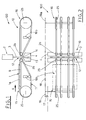
- figure 1 shows schematically a side view of a veil glazing line for processing of ceramic tiles, embedding a conveyor device according to a firs embodiment of the present invention;
- figure 2 shows schematically a top view of the veil glaze application line of figure 1;
- figure 3 shows schematically an enlarged portion of a branch of the conveyor shown in figure 1;
- figure 4 shows a cross sectional view of a belt according to section line IV-IV of figure 3;
- figure 5 shows schematically a top view of a second embodiment of the conveyor device made according to the present invention;
- figure 6 shows schematically a top view of a third embodiment of the conveyor device made according to the present invention.
- Referring now to figures 1 and 2,
numeral 100 indicates, in its whole, a line for veil application of a decorating product, e.g. glaze, toceramic tiles 1. Theline 100 embeds a first embodiment of aconveyor device 10 for transporting theaforesaid tiles 1 made according to the present invention. - The
glaze application line 100 moreover comprises a veil glazing apparatus 2, of a conventional type, which creates acontinuous veil 3 of glaze, a part thereof being fit to lay on a upper face 1a oftile 1 when thesame tile 1 crosses theveil 3. It is also provided, below theconveyor 100, acollecting tank 4 that collects the glaze which does not affect thetiles 1. - The veil glazing apparatus 2 is arranged crosswise with respect to the
conveyor 10. More particularly, in the described embodiment theglaze veil 3 has a straight shape. - The
conveyor device 10 has a substantially horizontal extension, and drives a series oftiles 1 according to a transporting direction V, through theglaze veil 3 and then downstream of thesame glaze veil 3 to subsequent known tiles processing stations. - The
conveyor device 10 comprises a pair of branches, respectively anupstream branch 15 and adownstream branch 16 with respect to theglaze veil 3 position, that are arranged subsequently along thetiles 1 processing path. Theupstream branch 15 and thedownstream branch 16 are separated by atransverse gap 12, arranged exactly at theglaze veil 3 fall, and having a shape identical to theglaze veil 3 shape. - In order to obtain a so shaped
transverse gap 12, theupstream branch 15 and thedownstream branch 16 of theconveyor 10 are suitably made with a plurality of very narrow, closedloop belts 11.Belts 11 are arranged parallel one each other, and at a mutual distance depending on the minimum size oftiles 1 to transport. - Each
belt 11 is driven and supported by a pair of pulleys, respectively adriving pulley 25, at the far conveyor end, with respect to thetransverse gap 12, and anidle pulley 26, at the proximal conveyor end. - The
driving pulleys 25 are suitably operated by motors for driving theupstream branch 15 and thedownstream branch 16 at the same transport speed. As a particular, and non limiting solution, asingle motor 17 can be provided, as schematically illustrated in figure 2, that operates on the shaft of theupstream branch 15 driving pulleys. The two shafts of bothconveyor branches transmission belt 18 and of a pair ofpulleys - According to the present invention, as a non-optimal solution, standard, very narrow polyurethane belts commonly used in the ceramic industry for transporting ceramic products could be used as
belts 11. - Nevertheless, in order to obtain a very narrow
transverse gap 12, the diameter of theidle pulleys 26 must be as small as possible. Since the aforesaid polyurethane belts, even if they are very narrow, cannot be bent to a sufficiently small diameter, their use in the conveyor made according to the present invention is limited to such applications where only large-sized or medium-sized tiles 1 have to be processed. - A further drawback that could arise when using the narrow polyurethane belts comes from that they are normally available as linear elements. In order to obtain a closed-loop belt, it is therefore necessary to exactly cut a linear belt, and then to weld them by end, with known techniques. The results of the aforesaid operation greatly depend on the operator's skill. A non-perfectly made welding operation results in an irregularity in the closed-loop belt, which can easily lead to produce jolts and shiftings to the transported tiles. Moreover, if they are non-perfectly made, the welding point becomes a weakness point in a closed-loop belt, which can cause a sudden break thereof.
- For the reason stated above, a very important aspect of the present invention is that the closed-loop belts are made using trapezoidal, toothed transmission belts, as shown in figure 3 and 4. Said belts are originally manufactured as closed-loop belts, they are sized to a number of standard lengths, and they are available on the market to be used for purposes totally different from articles transporting.
- Using the aforesaid kind of
belts 11 allows, first of all, to obtain very small bending radius (figure 3 shows the behaviour of the toothed bent around at a small diameter idle pulley 26). Moreover, because of the needs of the conventional, transmission use which is the appointed use for said belts, they are made very flexible, and they resist very well to a great number of washes carried out with water and most of the cleansing agents. - The
belts 11 are moreover supported, at the upper branch of theconveyor 10, bylinear guides 9, made with a suitable plastic material, as polystone or similar synthetic material. - In order to guarantee the correct tension to the
belts 11 theconveyor 10 comprises, for each one of theaforesaid belts 11, abelt tightener device 19, of known type. - At the longitudinal edges of the
transverse gap 12 there is moreover provided a pair of shapedplates toothed belts 11 from falling into the collectingtank 4. - When ceramic tiles have to be transported toward a veil glazing apparatus, both the
upstream branch 15 anddownstream branch 16 of theconveyor device 10 above described are started up to their nominal speed on the forwarding direction V by themotor 17. Theupstream branch 15 is driven directly by themotor 17, while thedownstream branch 16 is driven by means of thepulleys belt 18.Tiles 1 to be glazed are feed on the transportingbelts 11 of theupstream conveyor branch 15, with their front edge 1b arranged crosswise with respect to the forwarding direction V. - With no
tiles 1 passing through thetransverse gap 12, theglaze veil 3 falls totally into thegap 12, and therefrom it reaches the collectingtank 4, without affecting theconveyor 10. - When a
tile 1 comes near thetransverse gap 12, it trespasses thesame gap 12 and receives a layer of glaze while crossing theglaze veil 12. Since, because of the particular kind ofbelts 11 which has been used, thetransverse gap 12 width is very small, even smallsized tiles 1 can trespass thegap 12 and then engage the subsequentdownstream conveyor branch 16 with no problem. - In the above listed figures there is shown a
conveyor 10 embodiment comprising fourbelts 11 arranged side by side and spaced apart one each other. It is therefore obvious that the real number of belt used to make theconveyor 10, as well as their mutual distance, can be conveniently varied and chosen according to the transverse width of thetiles 1 to be transported. Substantially, it is to be expected that eventiles 1 of small transverse width have to be transported and processed, it will be convenient to improve the number of belts to arrange side by side, and therefore to reduce their mutual distance. - A second embodiment of the
conveyor 10 according to the present invention is shown in figure 5. - In this case, the veil glazing apparatus 2 is arranged so that its corresponding
glaze veil 3 is oriented slantwise with respect to theconveyor 10. More particularly, theglaze veil 3 has a straight shape, and it forms a non-zero angle A with the front edge 1 b of theincoming tile 1. - Because of the
transverse gap 12 shape, eachbelt 11 has of course a different length, progressively growing along the transverse direction. For the same reason, theshortest belt 11 of theupstream conveyor branch 15 counterfaces thelongest belt 11 of thedownstream conveyor branch 16. - When a
tile 1 reaches thetransverse gap 12, it becomes to engage progressively thesame gap 12 and theglaze veil 3. In fact, when a side of atile 1 engages thetransverse gap 12 and ceases to be supported by abelt 11 of theupstream conveyor branch 15, the remaining portion of thetile 1 is still supported by the other belts of thesame conveyor branch 15. When the opposite side of thetile 1 is not supported anymore by theunderlying belt 11 of theupstream conveyor branch 15, its first side has already trespassed thetransverse gap 12, and it is supported by at least onebelt 11 of thedownstream conveyor branch 16. In the way described above, it does never happens that a whole cross section of thetile 1 is engaged with thetransverse gap 12. - As far as it regards the interaction between the
tile 1 and theglaze veil 3, because of the engagement angle between the same tile and veil, the front edge 1b of thetile 1 "cuts" progressively theglaze veil 3 until the entire transverse extension of thetile 1 lays under thesame glaze veil 3. This engagement mode reduces greatly the "wrapping" effect exerted by the veil adhesion forces on the lower face of thetile 1. Thus the glaze veil does not wraps under the tile, and therefore it does not dirt its lower face nor the surfaces of the apparatus that subsequently engage the same tile. - A third embodiment of the present invention, shown in figure 6, is used together with veil glazing apparatus fit to generate a so called "bell" shape. These glazing apparatus are able to generate a glaze veil having a curvilinear shape. Therefore, in a corresponding
conveyor 10, theidle pulleys 26 and, by consequence, the belt length of theupstream conveyor branch 15 belts and of thedownstream conveyor branch 16 belts, follow the shape of the aforesaid curvilinear glaze veil, in order to obtain atransverse gap 12 having the same shape. - The advantages arising from the above described third embodiment of the present invention are substantially the same of those already described for the previous second embodiment.
- The present invention, as previously described, provides several, considerable advantages with respect to the conventional, prior art conveyor devices.
- First of all, the
transverse gap 12 can have a very small width even in aconveyor 10 made with narrow belts, and therefore it can achieve all the features and manufacturing advantages which are typical of the known narrow belt conveyors with respect to the technical solution comprising a closed-loop carpet. - Another advantage is that it is now possible to shape the
transverse gap 12 exactly as the shape of each veil glazing apparatus available in the market. - A further advantage is that the conveyor made according to the present invention prevents the tile lower face to be affected by the glaze veil, and then prevents the conveyor belts and the subsequent apparatus in the tiles processing line to be dirtied by the tiles.
- Another advantage is that the so-manufactured conveyor is extremely reliable, it is simple to set-up and that it is not damaged by continuous washes with flowing water to which it is subject when mounted in a processing line.
- The present invention has been described, with reference to the accompanying drawing tables, for exemplifying and non limiting purposes. It is therefore apparent that all the modifications or variants comprised in the following Claims will be considered as included in the invention scope.
Claims (10)
- Conveyor device for transporting ceramic tiles 1 or similar articles in an application line 100 for applying a veil of a decorating product, as glaze for ceramic tiles, on said tiles 1, said application line 100 comprising at least one veil glazing apparatus 2, fit to generate a continuous veil 3 of said decorating product and to lay down a part of said glaze veil 3 on a face 1a of said tiles 1, while the same tiles 1 are passing through said glaze veil 3 carried out by said conveyor device 10 according to a forwarding direction V, a collecting tank 4 for collecting the decorating product that does not affect said tiles 1, arranged below said conveyor device 10 and below said glaze veil 3, said conveyor device 10 being characterized in that it comprises one pair of conveyor branches, respectively a upstream conveyor branch 15 and a downstream conveyor branch 16, subsequently arranged and synchronously operated, between said upstream conveyor branch 15 and downstream conveyor branch 16 being provided a transverse gap 12, placed exactly to cross the falling surface of said glaze veil 3 and having a shape substantially following the glaze veil horizontal section, each one of the aforesaid conveyor branches 15,16 moreover comprising a plurality of narrow belts 11, shaped as closed-loop belts, arranged parallel one each the other and also parallel to the forwarding direction V.
- Conveyor device according to Claim 1, characterized in that all said narrow belts 11 are closed-loop transmission belts.
- Conveyor device according to Claim 2, characterized in that said closed-loop transmission belts 11 are toothed transmission belts.
- Conveyor device according to Claim 2, characterized in that said narrow belts 11 have a trapezoidal cross section.
- Conveyor device according to Claims 2, 3 or 4, characterized in that, for each one of said narrow belts 11, a corresponding straight guide is provided, fit to support the upper branch of said closed-loop narrow belts 11.
- Conveyor device according to each one of the previous Claims, characterized in that said narrow belts 11 are supported, at the end of their respective conveyor branch facing said transverse gap 12, by corresponding small diameter pulleys 26.
- Conveyor device according to Claim 1, characterized in that said transverse gap 12 has a substantially rectilinear shape, and it is oriented according to a predefined angle A with respect to the front edge 1b of the tiles 1 to be decorated, said glaze veil 3 also having a rectilinear shape and being oriented accordingly.
- Conveyor device according to Claim 1, characterized in that said transverse gap 12 has a curvilinear shape, and that the aforesaid glaze veil 3 has a curvilinear shape matching the transverse gap 12 shape.
- Conveyor device according to Claim 1, characterized in that, at the longitudinal edges of said transverse gap 12 there is provided one pair of shaped plates 13,14, fit to prevent the remains of dust and debris eventually transported by said narrow belts 11 to fall into said collecting tank 4.
- Conveyor device according to Claim 1, characterized in that said upstream conveyor branch 15 and downstream conveyor branch 16 are synchronously operated by a motor 17, by means of a transmission belt 18 and by means of one pair of pulleys 19,19a keyed on the driving pulleys shafts, respectively of said upstream conveyor branch 15 and downstream conveyor branch 16.
Applications Claiming Priority (1)
| Application Number | Priority Date | Filing Date | Title |
|---|---|---|---|
| ITBO20060069 ITBO20060069A1 (en) | 2006-02-07 | 2006-02-07 | CONVEYOR DEVICE FOR THE TRANSPORT OF TILES OR SIMILAR ITEMS IN A SAFETY APPLICATION LINE OF A DECORATIVE PRODUCT |
Publications (2)
| Publication Number | Publication Date |
|---|---|
| EP1815957A2 true EP1815957A2 (en) | 2007-08-08 |
| EP1815957A3 EP1815957A3 (en) | 2010-05-05 |
Family
ID=38050084
Family Applications (1)
| Application Number | Title | Priority Date | Filing Date |
|---|---|---|---|
| EP07101666A Withdrawn EP1815957A3 (en) | 2006-02-07 | 2007-02-02 | Conveyor for transporting ceramic tiles or similar articles |
Country Status (2)
| Country | Link |
|---|---|
| EP (1) | EP1815957A3 (en) |
| IT (1) | ITBO20060069A1 (en) |
Cited By (6)
| Publication number | Priority date | Publication date | Assignee | Title |
|---|---|---|---|---|
| ITUB20156310A1 (en) * | 2015-12-07 | 2017-06-07 | Air Power Group S P A | TILES COOLING SYSTEM IN A MEDIUM PRODUCTION PLANT |
| US10968042B2 (en) | 2017-01-20 | 2021-04-06 | Packsize Llc | Belt conveyor and system |
| CN116690770A (en) * | 2023-06-09 | 2023-09-05 | 佛山森兰特科技有限公司 | A kind of robot spray glaze method |
| CN117485903A (en) * | 2023-11-09 | 2024-02-02 | 淄博大川陶瓷科技有限公司 | Ceramic tile drenches glaze transport mechanism and drenches glaze system |
| WO2024200880A1 (en) * | 2023-03-29 | 2024-10-03 | Asitec Ceramic, S.L. | Conveying system for the enamelling of ceramic pieces |
| EP4748501A1 (en) | 2024-10-29 | 2026-05-27 | Air Power Group S.r.l. | Protection device for a ceramic tile conveyor line |
Families Citing this family (2)
| Publication number | Priority date | Publication date | Assignee | Title |
|---|---|---|---|---|
| CN106927188A (en) * | 2016-10-09 | 2017-07-07 | 广州精陶机电设备有限公司 | A kind of color code glaze line delivery platform docking mechanism |
| CN110405922B (en) * | 2019-09-06 | 2024-03-12 | 佛山市东鹏陶瓷有限公司 | An intelligent bell jar glazing system and its glazing method for rapid pilot-scale conversion of a single line into production |
Family Cites Families (5)
| Publication number | Priority date | Publication date | Assignee | Title |
|---|---|---|---|---|
| DE1080443B (en) * | 1957-04-13 | 1960-04-21 | Robert Buerkle & Co Maschinenf | Paint casting machine |
| GB1086301A (en) * | 1963-07-11 | 1967-10-11 | Factories Direction Ltd | Improvements in or relating to the application of adhesive coatings to veneers and other sheet materials |
| DE1257642C2 (en) * | 1964-08-14 | 1975-02-06 | CASTING HEAD ON LIQUID CASTING MACHINES FOR LOW-VISCOSE LIQUIDS WITH A FREE-FALLING FLOW CURTAIN | |
| CH597930A5 (en) * | 1976-09-10 | 1978-04-14 | Werner Kueny | |
| JP3451641B2 (en) * | 1992-11-25 | 2003-09-29 | 東陶機器株式会社 | Tile glazing method and glazing device |
-
2006
- 2006-02-07 IT ITBO20060069 patent/ITBO20060069A1/en unknown
-
2007
- 2007-02-02 EP EP07101666A patent/EP1815957A3/en not_active Withdrawn
Cited By (7)
| Publication number | Priority date | Publication date | Assignee | Title |
|---|---|---|---|---|
| ITUB20156310A1 (en) * | 2015-12-07 | 2017-06-07 | Air Power Group S P A | TILES COOLING SYSTEM IN A MEDIUM PRODUCTION PLANT |
| US10968042B2 (en) | 2017-01-20 | 2021-04-06 | Packsize Llc | Belt conveyor and system |
| WO2024200880A1 (en) * | 2023-03-29 | 2024-10-03 | Asitec Ceramic, S.L. | Conveying system for the enamelling of ceramic pieces |
| CN116690770A (en) * | 2023-06-09 | 2023-09-05 | 佛山森兰特科技有限公司 | A kind of robot spray glaze method |
| CN117485903A (en) * | 2023-11-09 | 2024-02-02 | 淄博大川陶瓷科技有限公司 | Ceramic tile drenches glaze transport mechanism and drenches glaze system |
| CN117485903B (en) * | 2023-11-09 | 2024-05-24 | 淄博大川陶瓷科技有限公司 | Ceramic tile drenches glaze transport mechanism and drenches glaze system |
| EP4748501A1 (en) | 2024-10-29 | 2026-05-27 | Air Power Group S.r.l. | Protection device for a ceramic tile conveyor line |
Also Published As
| Publication number | Publication date |
|---|---|
| EP1815957A3 (en) | 2010-05-05 |
| ITBO20060069A1 (en) | 2007-08-08 |
Similar Documents
| Publication | Publication Date | Title |
|---|---|---|
| US8312982B2 (en) | Apparatus for conveying and arranging bakery products | |
| US6907978B2 (en) | Methods and apparatuses for inducting articles onto a conveyor | |
| CA2199982C (en) | Belt refurbishing method and apparatus | |
| EP0557255B1 (en) | Storage and stacking device for sheets of laminar material | |
| KR102057582B1 (en) | Slitting Machine for Coil Strip | |
| JP7053311B2 (en) | Nori bundle end face shaving device | |
| EP1815957A3 (en) | Conveyor for transporting ceramic tiles or similar articles | |
| ATE190956T1 (en) | SLICE STACKER, ESPECIALLY FOR CHEESE SLICES | |
| KR20100066257A (en) | Cutting apparatus for rice cake | |
| CN101778716A (en) | Device and method for manufacturing sheet with cords | |
| CN104755395B (en) | For the taper scraper plate of conveyer belt | |
| WO2002007955A2 (en) | Apparatus for refurbishing belts | |
| WO2014192203A1 (en) | Cleaning brush for printed wiring board and cleaning machine using same | |
| DE202007009590U1 (en) | Disk-shaped objects e.g. sequential bulk goods, collecting conveyor, has burl band provided in end area of collecting band and raised over upper edge of collecting band by lifting device | |
| JP7583403B2 (en) | Dust removal device and entanglement prevention panel | |
| CN1223253C (en) | Device for conveying printed circuit boards | |
| JPH10109737A (en) | Alignment method and alignment device | |
| US6341771B1 (en) | Method of stacking strips of flexible material | |
| JP2751067B2 (en) | Transfer device | |
| EP1803352B1 (en) | Apparatus for handling toasted bread slices sent to packaging | |
| JP2015012108A (en) | Electronic component mounting apparatus and transport belt cleaning method | |
| EP2777828B1 (en) | Apparatus and method for sorting used bricks | |
| JP5441514B2 (en) | Transport device | |
| JPS6313896B2 (en) | ||
| JPH0448874Y2 (en) |
Legal Events
| Date | Code | Title | Description |
|---|---|---|---|
| PUAI | Public reference made under article 153(3) epc to a published international application that has entered the european phase |
Free format text: ORIGINAL CODE: 0009012 |
|
| AK | Designated contracting states |
Kind code of ref document: A2 Designated state(s): AT BE BG CH CY CZ DE DK EE ES FI FR GB GR HU IE IS IT LI LT LU LV MC NL PL PT RO SE SI SK TR |
|
| AX | Request for extension of the european patent |
Extension state: AL BA HR MK YU |
|
| PUAL | Search report despatched |
Free format text: ORIGINAL CODE: 0009013 |
|
| AK | Designated contracting states |
Kind code of ref document: A3 Designated state(s): AT BE BG CH CY CZ DE DK EE ES FI FR GB GR HU IE IS IT LI LT LU LV MC NL PL PT RO SE SI SK TR |
|
| AX | Request for extension of the european patent |
Extension state: AL BA HR MK RS |
|
| RIC1 | Information provided on ipc code assigned before grant |
Ipc: B65G 15/10 20060101ALI20100401BHEP Ipc: B05C 19/04 20060101ALI20100401BHEP Ipc: B28B 11/04 20060101AFI20070530BHEP |
|
| RIN1 | Information on inventor provided before grant (corrected) |
Inventor name: MALAVASI, PAOLO |
|
| AKY | No designation fees paid | ||
| REG | Reference to a national code |
Ref country code: DE Ref legal event code: 8566 |
|
| STAA | Information on the status of an ep patent application or granted ep patent |
Free format text: STATUS: THE APPLICATION IS DEEMED TO BE WITHDRAWN |
|
| 18D | Application deemed to be withdrawn |
Effective date: 20101108 |