EP1815040B1 - Method for deposition of a layer on a razor blade edge and razor blade - Google Patents
Method for deposition of a layer on a razor blade edge and razor blade Download PDFInfo
- Publication number
- EP1815040B1 EP1815040B1 EP04765607.9A EP04765607A EP1815040B1 EP 1815040 B1 EP1815040 B1 EP 1815040B1 EP 04765607 A EP04765607 A EP 04765607A EP 1815040 B1 EP1815040 B1 EP 1815040B1
- Authority
- EP
- European Patent Office
- Prior art keywords
- targets
- blade
- sputter
- layer
- enclosure
- Prior art date
- Legal status (The legal status is an assumption and is not a legal conclusion. Google has not performed a legal analysis and makes no representation as to the accuracy of the status listed.)
- Expired - Lifetime
Links
- 238000000034 method Methods 0.000 title claims description 41
- 230000008021 deposition Effects 0.000 title claims description 18
- 239000011651 chromium Substances 0.000 claims description 37
- 238000000576 coating method Methods 0.000 claims description 32
- 239000011248 coating agent Substances 0.000 claims description 29
- 229910052804 chromium Inorganic materials 0.000 claims description 21
- VYZAMTAEIAYCRO-UHFFFAOYSA-N Chromium Chemical compound [Cr] VYZAMTAEIAYCRO-UHFFFAOYSA-N 0.000 claims description 20
- OKTJSMMVPCPJKN-UHFFFAOYSA-N Carbon Chemical group [C] OKTJSMMVPCPJKN-UHFFFAOYSA-N 0.000 claims description 16
- 239000000463 material Substances 0.000 claims description 15
- 229910052799 carbon Inorganic materials 0.000 claims description 13
- 238000000992 sputter etching Methods 0.000 claims description 7
- 239000011368 organic material Substances 0.000 claims description 6
- 229910052751 metal Inorganic materials 0.000 claims description 5
- 239000002184 metal Substances 0.000 claims description 5
- 230000007423 decrease Effects 0.000 claims description 4
- 150000002500 ions Chemical class 0.000 claims description 4
- 229910002804 graphite Inorganic materials 0.000 claims description 3
- 239000010439 graphite Substances 0.000 claims description 3
- 229910052756 noble gas Inorganic materials 0.000 claims description 3
- 239000010410 layer Substances 0.000 description 36
- 238000000151 deposition Methods 0.000 description 16
- BASFCYQUMIYNBI-UHFFFAOYSA-N platinum Chemical compound [Pt] BASFCYQUMIYNBI-UHFFFAOYSA-N 0.000 description 12
- 239000010935 stainless steel Substances 0.000 description 11
- 229910001220 stainless steel Inorganic materials 0.000 description 11
- 238000004519 manufacturing process Methods 0.000 description 10
- 238000012360 testing method Methods 0.000 description 10
- 238000005520 cutting process Methods 0.000 description 9
- 239000004810 polytetrafluoroethylene Substances 0.000 description 8
- 229920001343 polytetrafluoroethylene Polymers 0.000 description 8
- XKRFYHLGVUSROY-UHFFFAOYSA-N Argon Chemical group [Ar] XKRFYHLGVUSROY-UHFFFAOYSA-N 0.000 description 7
- 238000004544 sputter deposition Methods 0.000 description 7
- 239000011229 interlayer Substances 0.000 description 5
- 230000009471 action Effects 0.000 description 4
- 229910052786 argon Inorganic materials 0.000 description 4
- 238000005259 measurement Methods 0.000 description 4
- 239000000203 mixture Substances 0.000 description 4
- 229910045601 alloy Inorganic materials 0.000 description 3
- 239000000956 alloy Substances 0.000 description 3
- MMAADVOQRITKKL-UHFFFAOYSA-N chromium platinum Chemical compound [Cr].[Pt] MMAADVOQRITKKL-UHFFFAOYSA-N 0.000 description 3
- 229920002313 fluoropolymer Polymers 0.000 description 3
- -1 for example Substances 0.000 description 3
- 239000007789 gas Substances 0.000 description 3
- 229910001260 Pt alloy Inorganic materials 0.000 description 2
- 239000011247 coating layer Substances 0.000 description 2
- 150000001875 compounds Chemical class 0.000 description 2
- 230000007797 corrosion Effects 0.000 description 2
- 238000005260 corrosion Methods 0.000 description 2
- 238000005137 deposition process Methods 0.000 description 2
- 238000011156 evaluation Methods 0.000 description 2
- 239000004811 fluoropolymer Substances 0.000 description 2
- 230000004907 flux Effects 0.000 description 2
- 238000010438 heat treatment Methods 0.000 description 2
- 230000006872 improvement Effects 0.000 description 2
- 238000011835 investigation Methods 0.000 description 2
- 230000007794 irritation Effects 0.000 description 2
- 238000011068 loading method Methods 0.000 description 2
- 230000003287 optical effect Effects 0.000 description 2
- 229910052697 platinum Inorganic materials 0.000 description 2
- 230000008569 process Effects 0.000 description 2
- 229910000831 Steel Inorganic materials 0.000 description 1
- 239000000919 ceramic Substances 0.000 description 1
- 239000004020 conductor Substances 0.000 description 1
- 238000013461 design Methods 0.000 description 1
- 238000000227 grinding Methods 0.000 description 1
- FXNGWBDIVIGISM-UHFFFAOYSA-N methylidynechromium Chemical compound [Cr]#[C] FXNGWBDIVIGISM-UHFFFAOYSA-N 0.000 description 1
- 229910052758 niobium Inorganic materials 0.000 description 1
- 239000010955 niobium Substances 0.000 description 1
- GUCVJGMIXFAOAE-UHFFFAOYSA-N niobium atom Chemical compound [Nb] GUCVJGMIXFAOAE-UHFFFAOYSA-N 0.000 description 1
- 239000012044 organic layer Substances 0.000 description 1
- 238000000717 platinum sputter deposition Methods 0.000 description 1
- 229920000642 polymer Polymers 0.000 description 1
- 238000005245 sintering Methods 0.000 description 1
- 238000005507 spraying Methods 0.000 description 1
- 238000005477 sputtering target Methods 0.000 description 1
- 239000010959 steel Substances 0.000 description 1
- 238000005728 strengthening Methods 0.000 description 1
- 239000000758 substrate Substances 0.000 description 1
- 238000012546 transfer Methods 0.000 description 1
- WFKWXMTUELFFGS-UHFFFAOYSA-N tungsten Chemical compound [W] WFKWXMTUELFFGS-UHFFFAOYSA-N 0.000 description 1
- 229910052721 tungsten Inorganic materials 0.000 description 1
- 239000010937 tungsten Substances 0.000 description 1
Images

Classifications
-
- C—CHEMISTRY; METALLURGY
- C23—COATING METALLIC MATERIAL; COATING MATERIAL WITH METALLIC MATERIAL; CHEMICAL SURFACE TREATMENT; DIFFUSION TREATMENT OF METALLIC MATERIAL; COATING BY VACUUM EVAPORATION, BY SPUTTERING, BY ION IMPLANTATION OR BY CHEMICAL VAPOUR DEPOSITION, IN GENERAL; INHIBITING CORROSION OF METALLIC MATERIAL OR INCRUSTATION IN GENERAL
- C23C—COATING METALLIC MATERIAL; COATING MATERIAL WITH METALLIC MATERIAL; SURFACE TREATMENT OF METALLIC MATERIAL BY DIFFUSION INTO THE SURFACE, BY CHEMICAL CONVERSION OR SUBSTITUTION; COATING BY VACUUM EVAPORATION, BY SPUTTERING, BY ION IMPLANTATION OR BY CHEMICAL VAPOUR DEPOSITION, IN GENERAL
- C23C14/00—Coating by vacuum evaporation, by sputtering or by ion implantation of the coating forming material
- C23C14/22—Coating by vacuum evaporation, by sputtering or by ion implantation of the coating forming material characterised by the process of coating
- C23C14/34—Sputtering
-
- B—PERFORMING OPERATIONS; TRANSPORTING
- B26—HAND CUTTING TOOLS; CUTTING; SEVERING
- B26B—HAND-HELD CUTTING TOOLS NOT OTHERWISE PROVIDED FOR
- B26B21/00—Razors of the open or knife type; Safety razors or other shaving implements of the planing type; Hair-trimming devices involving a razor-blade; Equipment therefor
- B26B21/54—Razor-blades
- B26B21/58—Razor-blades characterised by the material
- B26B21/60—Razor-blades characterised by the material by the coating material
-
- C—CHEMISTRY; METALLURGY
- C23—COATING METALLIC MATERIAL; COATING MATERIAL WITH METALLIC MATERIAL; CHEMICAL SURFACE TREATMENT; DIFFUSION TREATMENT OF METALLIC MATERIAL; COATING BY VACUUM EVAPORATION, BY SPUTTERING, BY ION IMPLANTATION OR BY CHEMICAL VAPOUR DEPOSITION, IN GENERAL; INHIBITING CORROSION OF METALLIC MATERIAL OR INCRUSTATION IN GENERAL
- C23C—COATING METALLIC MATERIAL; COATING MATERIAL WITH METALLIC MATERIAL; SURFACE TREATMENT OF METALLIC MATERIAL BY DIFFUSION INTO THE SURFACE, BY CHEMICAL CONVERSION OR SUBSTITUTION; COATING BY VACUUM EVAPORATION, BY SPUTTERING, BY ION IMPLANTATION OR BY CHEMICAL VAPOUR DEPOSITION, IN GENERAL
- C23C14/00—Coating by vacuum evaporation, by sputtering or by ion implantation of the coating forming material
- C23C14/02—Pretreatment of the material to be coated
- C23C14/024—Deposition of sublayers, e.g. to promote adhesion of the coating
- C23C14/025—Metallic sublayers
-
- C—CHEMISTRY; METALLURGY
- C23—COATING METALLIC MATERIAL; COATING MATERIAL WITH METALLIC MATERIAL; CHEMICAL SURFACE TREATMENT; DIFFUSION TREATMENT OF METALLIC MATERIAL; COATING BY VACUUM EVAPORATION, BY SPUTTERING, BY ION IMPLANTATION OR BY CHEMICAL VAPOUR DEPOSITION, IN GENERAL; INHIBITING CORROSION OF METALLIC MATERIAL OR INCRUSTATION IN GENERAL
- C23C—COATING METALLIC MATERIAL; COATING MATERIAL WITH METALLIC MATERIAL; SURFACE TREATMENT OF METALLIC MATERIAL BY DIFFUSION INTO THE SURFACE, BY CHEMICAL CONVERSION OR SUBSTITUTION; COATING BY VACUUM EVAPORATION, BY SPUTTERING, BY ION IMPLANTATION OR BY CHEMICAL VAPOUR DEPOSITION, IN GENERAL
- C23C14/00—Coating by vacuum evaporation, by sputtering or by ion implantation of the coating forming material
- C23C14/06—Coating by vacuum evaporation, by sputtering or by ion implantation of the coating forming material characterised by the coating material
- C23C14/0635—Carbides
-
- C—CHEMISTRY; METALLURGY
- C23—COATING METALLIC MATERIAL; COATING MATERIAL WITH METALLIC MATERIAL; CHEMICAL SURFACE TREATMENT; DIFFUSION TREATMENT OF METALLIC MATERIAL; COATING BY VACUUM EVAPORATION, BY SPUTTERING, BY ION IMPLANTATION OR BY CHEMICAL VAPOUR DEPOSITION, IN GENERAL; INHIBITING CORROSION OF METALLIC MATERIAL OR INCRUSTATION IN GENERAL
- C23C—COATING METALLIC MATERIAL; COATING MATERIAL WITH METALLIC MATERIAL; SURFACE TREATMENT OF METALLIC MATERIAL BY DIFFUSION INTO THE SURFACE, BY CHEMICAL CONVERSION OR SUBSTITUTION; COATING BY VACUUM EVAPORATION, BY SPUTTERING, BY ION IMPLANTATION OR BY CHEMICAL VAPOUR DEPOSITION, IN GENERAL
- C23C14/00—Coating by vacuum evaporation, by sputtering or by ion implantation of the coating forming material
- C23C14/22—Coating by vacuum evaporation, by sputtering or by ion implantation of the coating forming material characterised by the process of coating
- C23C14/34—Sputtering
- C23C14/35—Sputtering by application of a magnetic field, e.g. magnetron sputtering
- C23C14/352—Sputtering by application of a magnetic field, e.g. magnetron sputtering using more than one target
-
- C—CHEMISTRY; METALLURGY
- C23—COATING METALLIC MATERIAL; COATING MATERIAL WITH METALLIC MATERIAL; CHEMICAL SURFACE TREATMENT; DIFFUSION TREATMENT OF METALLIC MATERIAL; COATING BY VACUUM EVAPORATION, BY SPUTTERING, BY ION IMPLANTATION OR BY CHEMICAL VAPOUR DEPOSITION, IN GENERAL; INHIBITING CORROSION OF METALLIC MATERIAL OR INCRUSTATION IN GENERAL
- C23C—COATING METALLIC MATERIAL; COATING MATERIAL WITH METALLIC MATERIAL; SURFACE TREATMENT OF METALLIC MATERIAL BY DIFFUSION INTO THE SURFACE, BY CHEMICAL CONVERSION OR SUBSTITUTION; COATING BY VACUUM EVAPORATION, BY SPUTTERING, BY ION IMPLANTATION OR BY CHEMICAL VAPOUR DEPOSITION, IN GENERAL
- C23C14/00—Coating by vacuum evaporation, by sputtering or by ion implantation of the coating forming material
- C23C14/22—Coating by vacuum evaporation, by sputtering or by ion implantation of the coating forming material characterised by the process of coating
- C23C14/56—Apparatus specially adapted for continuous coating; Arrangements for maintaining the vacuum, e.g. vacuum locks
- C23C14/568—Transferring the substrates through a series of coating stations
Definitions
- the invention relates to a method for deposition of a layer on a razor blade edge, and a razor blade.
- Razor blades are generally made of a ceramic or steel substrate covered by a hard coating.
- An outer layer of an organic material is also often deposited on the hard coating, to reduce friction of the razor blade on the skin when shaving.
- This organic layer is often a PTFE material.
- the hard coating usually primarily acts as a strengthening coating, in order to strengthen the blade and improve its life expectancy.
- Some particular materials providing a very good strength property like for example chromium-platinum alloys, have been deposited in the past by placing the razor blade edges in front of a chromium-platinum alloy sputtering target and sputtering said target in order to deposit chromium- platinum on the razor blade edge. Yet, the proportions of chromium and platinum in the deposited coating are fixed by the proportions of chromium and platinum in the target.
- the invention provides a method for deposition of a layer on a razor blade edge of a razor blade, the blade edge having two sides converging toward a tip, said layer comprising at least two components, in an enclosure comprising at least a first and a second sputter targets, said sputter targets comprising mainly one respective of said components to be deposited on said edge and being adapted, in operation, to release said component in the enclosure, said method comprising a step (a) wherein, under operation of both targets, the razor blade is moved relatively to said first and second targets to pass alternately in the vicinity of each target, with its tip directed toward the target.
- the method makes it possible to design coating layers with varying properties without having to manually replace the sputter targets and/or the blade edges during coating. Furthermore, the method enables the coating of many razor blade edges at a time.
- Fig. 1 is a horizontal sectional view of a sputtering apparatus used for implementation of the method according to the invention.
- the sputtering apparatus comprises an enclosure with an internal wall 1, for example cylindrical, wherein a low pressure atmosphere can be formed.
- the enclosure comprises sputter targets 2, 3, 4, 5 placed in a cross relationship, facing one another two by two. Any other suitable apparatus, such as for example an in-line sputtering apparatus with at least two sputter targets, could be used for implementation of the method according to the invention.
- First and third sputter targets 2 and 4 facing one another, mainly comprise a first component to be deposited on razor blade edges.
- first and third sputter targets 2 and 4 comprise a material providing good hardness and strength properties.
- First and third sputter targets comprise for example carbon in the form of graphite.
- Second and fourth sputter targets 3 and 5 facing one another, mainly comprise a second component to be deposited on razor blade edges.
- second and fourth sputter targets 3 and 5 comprise a material providing good adhesion of first component on the razor blade edge or/and on organic material.
- Second and fourth sputter targets comprise for example a metal, for example, chromium, niobium or tungsten.
- the first, second, third and fourth targets could be elemental targets, or compound targets containing a compound of at least two elements to be deposited on the blade edge.
- Each sputter target 2, 3, 4, 5 is attached on a magnetron 12, 13, 14, 15, respectively, located between the target and the wall 1.
- the magnetron can be operated to enhance the deposition speed of components to be deposited on the razor blade edges.
- a given polarity is chosen for three of the magnetrons, and the opposite polarity for a fourth magnetron.
- the magnetrons can for example be unbalanced magnetrons, of the type comprising three magnets, a central magnet 12a being surrounded by two stronger side magnets 12b and 12c with opposite polarity, as will be apparent from Fig. 1 .
- Magnetrons 13, 14 and 15 also are unbalanced magnetrons.
- the central magnets of three of the four magnetrons have a given polarity while the central magnet of the other magnetron has the opposite polarity.
- polarity of central magnets 12a, 15a and 14a is chosen South, while polarity of central magnet 13a is chosen North.
- polarity of the side magnets is chosen accordingly.
- the targets can be operated by application of a DC current on the targets, provided by a DC power supply (not shown) connected to the targets.
- a DC power supply (not shown) connected to the targets.
- Each target can be connected alternatively or simultaneously with the DC power supply.
- the apparatus comprises a vacuum pump 6 which can be operated to provide a certain degree of vacuum in the enclosure.
- the apparatus also comprises a source of argon atoms 7 which is adapted to release a given pressure of argon in the enclosure.
- a source of argon atoms 7 which is adapted to release a given pressure of argon in the enclosure.
- Other noble gas could be used.
- a rotating carousel 8 can be disposed, which is adapted to move, for example to rotate around a vertical axis (z).
- the carousel is part of the apparatus, or can be removably maintained inside the apparatus for the deposition process.
- the carousel holds bayonets (8 bayonets, as exemplified on Fig. 1 ) which hold stacked razor blades to be coated, of the type used in mechanical razors. Many razor blade edges can thus be coated during the same deposition process.
- the carousel is connected to a DC power supply 11 able to provide a DC voltage bias on the razor blades.
- the razor blades 10 are for example made of an electrically conducting material, for example stainless steel, and can have been preliminarily submitted to grinding operations that provide a sharpened edge 10 of two sides 10a, 10b that converge towards tip 10c (see for example Fig. 4 and 5 ).
- the razor blades are loaded in the bayonets so that, in the apparatus, the tip 10c is directed towards the enclosure wall (and the target).
- a sputter target for example chromium target 3
- argon ions bombard said target to release in the enclosure atoms and ions 19 of the component of the target.
- the target atoms travel towards the blade because of the velocity they acquired due to transfer of momentum from argon ions (ballistic component of the flux) and because of concentration gradients (diffusive component of the flux).
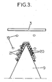
- the target ions are also attracted to the razor blade by the applied bias. They deposit on the blade edge 9 where graphite atoms 20 (black dots on Fig. 3 ) and other chromium atoms 21 (white dots on Fig. 3 ) have already deposited when the razor blade previously passed in the vicinity of a carbon target (for example carbon target 2 on Fig. 1 ) and a chromium target (for example chromium target 5 on Fig. 1 ) respectively.
- a carbon target for example carbon target 2 on Fig. 1
- a chromium target for example chromium target 5 on Fig.
- a preliminary sputter-etching step can be performed in order to clean and/or remove some materials from the tip 10c and sides 10a, 10b of the razor blades.
- a preliminary sputter deposition step of an interlayer of at least one of the two components (for example chromium) can be performed.
- the internal pressure is set to 3.10 -3 Torr.
- Second sputter targets 3 and 5 are operated by a DC current of 1.5 A, and a 300 V DC voltage is applied to the razor blades while the carousel is rotating at about 5.5 rpm.
- the enclosure wall and targets 2 and 4 are grounded.
- the operating parameters, and .simultaneous fast rotation speed (in general between 4 and 40 rpm) enable equal sputter deposition on all razor blade edges.
- the apparatus can also be used in order to deposit a homogeneous layer comprising both components in a given proportion.
- the operating parameters are chosen in order to provide said proportion.
- This coating can be applied directly on the razor blade or on an interlayer of one of the components as described hereinabove.
- chromium-containing sputter targets 3, 5 are operated by a DC current between 0.5 and 20 A.
- Carbon-containing sputter targets 2, 4 are operated by a DC current between 0.5 and 20 A.
- a negative DC voltage of about 100 to 2000 V is applied on the blades.
- the ratio of the intensities applied on each target is chosen in order to provide with a given proportion of the components in the homogeneous coating.
- the method thus enables, during production, to easily adapt the coating properties to various customer requirements. For example, more corrosion resistance properties could be needed in some countries, and the process parameters could be easily adapted to increase the amount of corrosion resistant material for razor blades manufactured for these countries.
- the ratio of the concentrations of both components can be varied by changing the ratio of the intensities applied on the various targets. If one of the components provides good adhesion to outer organic coatings such as PTFE, for example chromium, its relative concentration can be increased in order to improve adhesion of the PTFE coating.
- PTFE for example chromium
- a top layer comprising only one of the two components, for example chromium.
- Pressure in the enclosure is 3.10 -3 Torr.
- the chromium sputter targets 3 and 5 are operated by a DC current of 1.5 A. DC voltage of 100 - 1000 V is applied on the blades.
- the carbon targets 2 and 4 are grounded. The carousel still rotates at about 5.5 rpm.
- a top layer of chromium is used to provide good adhesion to outer organic coatings such as PTFE which is usually deposited on the razor blade after deposition of the hard coating.
- the coated razor blade can be sputter-etched. After setting argon gas pressure and DC voltage on the blades, chromium sputter targets are operated while carbon sputter targets are grounded.
- a fluorinated polymer final coating is applied on the sputter-deposited film at the cutting edge of the blade.
- Application of the polymer can be made by a spraying method followed by sintering.
- FIG. 4 and 5 Examples of razor blades according to the invention can be seen on Fig. 4 and 5 .
- a stainless steel blade 10 is coated with a 30-200 nm thick homogeneous layer 16 of chromium and carbon in graphite form.
- the homogeneous layer 16 is coated with PTFE layer 17.
- Chromium carbon layer 16 comprises a first portion 16a of homogeneous carbon and chromium. In 10 nm thick second portion 16b, chromium content increases up to the interface with PTFE layer 17.
- pulsed DC bias consisting of a DC continuous component and a pulse component superimposed on the DC continuous component, at a frequency of about 50-250 kHz, could be applied on the razor blades.
- the chamber After loading the blade bayonets on the rotating carousel, the chamber is evacuated up to a base pressure of 10 -5 Torr. Then Ar gas is inserted into the chamber for a sputter etching step. Rotation of the blade bayonets begins at a constant speed of 11 rpm and the two Cr targets are operated under DC current control and DC voltage is applied on the stainless steel blades for 4 minutes.
- the chamber pressure is adjusted to 3 mTorr.
- the Cr targets 1 and 3 are operated under DC current control at 1.5 Amps while a DC voltage of 300 V is applied on the rotating blades. Adjusting the deposition time a Cr layer of 20 nm is deposited on the edge of the blade samples.
- C targets 2 and 4 are switched on.
- the two C targets (2 and 4) and the two Cr targets (1 and 3) operate simultaneously, with the current on the Cr targets being 1.2 Amps and the current on each C target being 6 Amps.
- a DC voltage of 450 V is applied on the rotating blades.
- a Cr-C homogeneous alloy film of 50 nm is deposited on the Cr layer.
- a fluoropolymer final layer (PTFE) of 500 nm is deposited, mainly to provide a lower friction of the blade surface.
- the damage imposed on the blade edge after 10 cuts during the above-described test was also evaluated with the aid of an optical microscope.
- the damage on the blade edge was quantified in terms of area of missing material (i.e. material that has been broken and removed from the edge).
- Cr-C coated blades resulted in an 85 % decrease of the missing material area as compared with blades with standard production Cr-Pt coating. This result shows the increased durability of the blades with the new Cr-C coating (see Table 1).
- Table 1 Test results for first example blades Sample Force at 10th cut (Kg) Area of Damages ( ⁇ m2) Blade with standard production coating 1.761 33288 Blade sample 1 1.455 4985 Blade sample 2 1.464 3739 Blade sample 3 1.455 3290 Blade sample 4 1.508 3390 Blade sample 5 1.45 1741 Blade sample 6 1.447 1263 Blade sample 7 1.435 1538 Blade sample 8 1.372 1280 Blade sample 9 1.345 1348 Blade sample 10 1.326 1879
- the chamber is evacuated up to a base pressure of 10 -5 Torr. Then Ar gas is inserted for a sputter etching step. Rotation of the blade bayonets begins at a constant speed of 11 rpm and the two Cr targets are operated under DC current control while DC voltage is applied on the stainless steel blades for 4 minutes.
- the chamber pressure is adjusted to 3 mTorr.
- the Cr targets 1 and 3 are operated under DC current control at 1.5 Amps while a DC voltage of 300 V is applied on the rotating blades. Adjusting the deposition time a Cr layer of 20 nm is deposited on the edge of the blade samples.
- C targets 2 and 4 are switched on.
- the two C targets (2 and 4) and the two Cr targets (1 and 3) operate simultaneously, with the current on the Cr targets being 2.85 Amps and the current on each C target being 1.5 Amps.
- a DC voltage of 450 V is applied on the rotating blades.
- a Cr-C homogeneous alloy film of 60 nm is deposited on the Cr layer.
- a fluoropolymer final layer (PTFE) of 500 nm is deposited, mainly to provide a lower friction of the blade surface.
- Table 2 Test results for second example blades Sample Force at 10th cut (Kg) Area of Damages ( ⁇ m2) Blade with standard production coating 1.635 31258 Blade sample 1 1.296 1857 Blade sample 2 1.404 2014 Blade sample 3 1.421 1664 Blade sample 4 1.4 1438 Blade sample 5 1.41 1127 Blade sample 6 1.391 1121 Blade sample 7 1.325 2299 Blade sample 8 1.381 1356 Blade sample 9 1.353 2486 Blade sample 10 1.356 1569
- the damage imposed on the blade edge after 10 cuts during the above-described test was also evaluated with the aid of an optical microscope.
- the damage on the blade edge was quantified in terms of area of missing material (i.e. material that has been broken and removed from the edge).
- Cr-C coated blades resulted in a 90 % decrease of the missing material area as compared with blades with standard production Cr-Pt coating. This result shows the increased durability of the blades with the new Cr-C coating (see Table 2).
Landscapes
- Chemical & Material Sciences (AREA)
- Mechanical Engineering (AREA)
- Engineering & Computer Science (AREA)
- Organic Chemistry (AREA)
- Materials Engineering (AREA)
- Metallurgy (AREA)
- Chemical Kinetics & Catalysis (AREA)
- Life Sciences & Earth Sciences (AREA)
- Forests & Forestry (AREA)
- Physical Vapour Deposition (AREA)
- Dry Shavers And Clippers (AREA)
- Application Of Or Painting With Fluid Materials (AREA)
- Perforating, Stamping-Out Or Severing By Means Other Than Cutting (AREA)
Description
- The invention relates to a method for deposition of a layer on a razor blade edge, and a razor blade.
- Razor blades are generally made of a ceramic or steel substrate covered by a hard coating. An outer layer of an organic material is also often deposited on the hard coating, to reduce friction of the razor blade on the skin when shaving. This organic layer is often a PTFE material.
- The hard coating usually primarily acts as a strengthening coating, in order to strengthen the blade and improve its life expectancy. Some particular materials providing a very good strength property, like for example chromium-platinum alloys, have been deposited in the past by placing the razor blade edges in front of a chromium-platinum alloy sputtering target and sputtering said target in order to deposit chromium- platinum on the razor blade edge. Yet, the proportions of chromium and platinum in the deposited coating are fixed by the proportions of chromium and platinum in the target.
- It is an object of the present invention to provide a new method for the deposition on a razor blade of a hard layer comprising at least two components.
- To this end, the invention provides a method for deposition of a layer on a razor blade edge of a razor blade, the blade edge having two sides converging toward a tip, said layer comprising at least two components, in an enclosure comprising at least a first and a second sputter targets, said sputter targets comprising mainly one respective of said components to be deposited on said edge and being adapted, in operation, to release said component in the enclosure, said method comprising a step (a) wherein, under operation of both targets, the razor blade is moved relatively to said first and second targets to pass alternately in the vicinity of each target, with its tip directed toward the target.
- The method makes it possible to design coating layers with varying properties without having to manually replace the sputter targets and/or the blade edges during coating. Furthermore, the method enables the coating of many razor blade edges at a time.
- In particular embodiments of the method according to the invention, one might also use the following features:
- said first and second sputter targets are operated by bombardment of noble gas ions,
- during step (a) a magnetic field is generated by magnet devices in the vicinity of said targets;
- the magnet devices each include at least a central magnet disposed between two side magnets and with opposed polarity, said side magnets being stronger than said central magnet;
- the enclosure comprises first, second, third and fourth sputter targets, said first and third sputter targets facing each other and carrying said first component, said second and fourth sputter targets facing each other and carrying said second component, each of said first, second, third and fourth targets having a magnet device and said magnet devices of said second, third and fourth sputter targets being of same polarity;
- said first, second, third and fourth targets are fixed in the enclosure, and the razor blade is rotated relative to the enclosure, so that it passes successively in front of each of said first, second, third and fourth targets,
- the blade is rotated at a rotation speed over 4 rpm,
- said second component is a metal, said second and fourth targets are operated by a DC current with an intensity comprised between 0.5 and 20 A;
- said first element is carbon, said first and third targets comprise graphite, and said first and third targets are operated by a DC current with an intensity comprised between 0.5 and 20 A;
- said second component provides improved adherence to an organic material, and, during step (a), a ratio of the intensities applied on said first and second targets decreases;
- said metal is chromium; the blade edge is submitted to a DC voltage comprised between 100 and 1000 V;
- the blade edge is submitted to a pulsed DC voltage;
- said layer has a given proportion of said components, each target is operated under given operation parameters, the method further including a step (e), prior to step (a), wherein said operation parameters are chosen in order to provide said proportion;
- prior to step (a), razor blades are stacked in a carrousel; the method further comprises a sputter-etching step (b) wherein material is removed from the blade by simultaneously operating said second targets and applying a DC voltage on the blade;
- step (b) is performed before step (a);
- the method further comprises a step (c) wherein an additional layer comprising at least one of said components is deposited by operating only the targets comprising the components of said additional layer;
- step (c) is performed before step (a);
- step (a) is performed before step (c);
- the method further comprises a step (d) wherein an outer layer comprising an organic material is applied on said coating.
- Other features and advantages of the invention will be apparent from the following description, drawings and claims.
- On the drawings:
-
Fig. 1 is an horizontal sectional view of an apparatus adapted for implementing a method according to one particular embodiment of the invention, -
Fig. 2 is a vertical sectional view of the apparatus ofFig. 1 , -
Fig. 3 is a schematic representation of a blade during the coating process, -
Fig. 4 is a section of a razor blade according to one embodiment of the invention, and -
Fig. 5 is a section of a razor blade according to another embodiment of the invention. - On the drawings, corresponding or similar elements have the same reference numbers.
-
Fig. 1 is a horizontal sectional view of a sputtering apparatus used for implementation of the method according to the invention. The sputtering apparatus comprises an enclosure with an internal wall 1, for example cylindrical, wherein a low pressure atmosphere can be formed. The enclosure comprisessputter targets - First and third sputter targets 2 and 4, facing one another, mainly comprise a first component to be deposited on razor blade edges. For example, first and third sputter targets 2 and 4 comprise a material providing good hardness and strength properties. First and third sputter targets comprise for example carbon in the form of graphite.
- - Second and fourth sputter targets 3 and 5, facing one another, mainly comprise a second component to be deposited on razor blade edges. For example, second and fourth sputter targets 3 and 5 comprise a material providing good adhesion of first component on the razor blade edge or/and on organic material. Second and fourth sputter targets comprise for example a metal, for example, chromium, niobium or tungsten.
- The first, second, third and fourth targets could be elemental targets, or compound targets containing a compound of at least two elements to be deposited on the blade edge.
- Each
sputter target magnetron - In an embodiment, a given polarity is chosen for three of the magnetrons, and the opposite polarity for a fourth magnetron.
- The magnetrons can for example be unbalanced magnetrons, of the type comprising three magnets, a
central magnet 12a being surrounded by twostronger side magnets Fig. 1 .Magnetrons - In a way similar to the above description, the central magnets of three of the four magnetrons have a given polarity while the central magnet of the other magnetron has the opposite polarity. For example, polarity of
central magnets 12a, 15a and 14a is chosen South, while polarity of central magnet 13a is chosen North. Of course, polarity of the side magnets is chosen accordingly. - The targets can be operated by application of a DC current on the targets, provided by a DC power supply (not shown) connected to the targets. Each target can be connected alternatively or simultaneously with the DC power supply.
- The apparatus comprises a vacuum pump 6 which can be operated to provide a certain degree of vacuum in the enclosure.
- The apparatus also comprises a source of argon atoms 7 which is adapted to release a given pressure of argon in the enclosure. Other noble gas could be used.
- In the apparatus a rotating carousel 8 can be disposed, which is adapted to move, for example to rotate around a vertical axis (z). The carousel is part of the apparatus, or can be removably maintained inside the apparatus for the deposition process. The carousel holds bayonets (8 bayonets, as exemplified on
Fig. 1 ) which hold stacked razor blades to be coated, of the type used in mechanical razors. Many razor blade edges can thus be coated during the same deposition process. - The carousel is connected to a
DC power supply 11 able to provide a DC voltage bias on the razor blades. - The
razor blades 10 are for example made of an electrically conducting material, for example stainless steel, and can have been preliminarily submitted to grinding operations that provide a sharpenededge 10 of twosides Fig. 4 and 5 ). The razor blades are loaded in the bayonets so that, in the apparatus, the tip 10c is directed towards the enclosure wall (and the target). - According to the principles of sputter-deposition, as shown on
Fig. 3 , when a sputter target (for example chromium target 3) is operated, argon ions bombard said target to release in the enclosure atoms andions 19 of the component of the target. The target atoms travel towards the blade because of the velocity they acquired due to transfer of momentum from argon ions (ballistic component of the flux) and because of concentration gradients (diffusive component of the flux). The target ions are also attracted to the razor blade by the applied bias. They deposit on theblade edge 9 where graphite atoms 20 (black dots onFig. 3 ) and other chromium atoms 21 (white dots onFig. 3 ) have already deposited when the razor blade previously passed in the vicinity of a carbon target (forexample carbon target 2 onFig. 1 ) and a chromium target (forexample chromium target 5 onFig. 1 ) respectively. - Once the razor blade edges have been loaded in the enclosure, it is closed, and the enclosure is evacuated by pump 6 to reach a base pressure of about 10-5Torr.
- A preliminary sputter-etching step can be performed in order to clean and/or remove some materials from the tip 10c and
sides - A preliminary sputter deposition step of an interlayer of at least one of the two components (for example chromium) can be performed. The internal pressure is set to 3.10-3 Torr.
Second sputter targets - The operating parameters, and .simultaneous fast rotation speed (in general between 4 and 40 rpm) enable equal sputter deposition on all razor blade edges.
- By switching off the DC current applied on the second sputter targets, and by providing a DC current on the
first sputter targets - It is thus possible to coat a very large number of razor blade edges with two homogeneous layers each including one component, with very few handling operations.
- The apparatus can also be used in order to deposit a homogeneous layer comprising both components in a given proportion. The operating parameters are chosen in order to provide said proportion. This coating can be applied directly on the razor blade or on an interlayer of one of the components as described hereinabove.
- After deposition of the interlayer, the carousel still rotating at the speed of 5.5 rpm, chromium-containing
sputter targets sputter targets - The ratio of the intensities applied on each target is chosen in order to provide with a given proportion of the components in the homogeneous coating. The method thus enables, during production, to easily adapt the coating properties to various customer requirements. For example, more corrosion resistance properties could be needed in some countries, and the process parameters could be easily adapted to increase the amount of corrosion resistant material for razor blades manufactured for these countries.
- During the end of the deposition of the homogeneous layer, the ratio of the concentrations of both components can be varied by changing the ratio of the intensities applied on the various targets. If one of the components provides good adhesion to outer organic coatings such as PTFE, for example chromium, its relative concentration can be increased in order to improve adhesion of the PTFE coating.
- It is also possible to provide with a top layer comprising only one of the two components, for example chromium. Pressure in the enclosure is 3.10-3 Torr. The
chromium sputter targets - A top layer of chromium is used to provide good adhesion to outer organic coatings such as PTFE which is usually deposited on the razor blade after deposition of the hard coating.
- After deposition, the coated razor blade can be sputter-etched. After setting argon gas pressure and DC voltage on the blades, chromium sputter targets are operated while carbon sputter targets are grounded.
- That way, material is removed from the topmost coating layer in order to re-sharpen the blade.
- Finally, a fluorinated polymer final coating is applied on the sputter-deposited film at the cutting edge of the blade. Application of the polymer can be made by a spraying method followed by sintering.
- Examples of razor blades according to the invention can be seen on
Fig. 4 and 5 . - On
Fig. 4 , astainless steel blade 10 is coated with a 30-200 nm thickhomogeneous layer 16 of chromium and carbon in graphite form. Thehomogeneous layer 16 is coated withPTFE layer 17. - On
Fig. 5 , astainless steel blade 10 is coated with a 20-30 nmthick chromium interlayer 18.Chromium carbon layer 16 comprises a first portion 16a of homogeneous carbon and chromium. In 10 nm thick second portion 16b, chromium content increases up to the interface withPTFE layer 17. - Of course, the invention is not limited to using only two components.
- Instead of DC voltage, pulsed DC bias consisting of a DC continuous component and a pulse component superimposed on the DC continuous component, at a frequency of about 50-250 kHz, could be applied on the razor blades.
- Two detailed process examples are given below.
- After loading the blade bayonets on the rotating carousel, the chamber is evacuated up to a base pressure of 10-5 Torr. Then Ar gas is inserted into the chamber for a sputter etching step. Rotation of the blade bayonets begins at a constant speed of 11 rpm and the two Cr targets are operated under DC current control and DC voltage is applied on the stainless steel blades for 4 minutes.
- After the end of sputter etching step the chamber pressure is adjusted to 3 mTorr. The Cr targets 1 and 3 are operated under DC current control at 1.5 Amps while a DC voltage of 300 V is applied on the rotating blades. Adjusting the deposition time a Cr layer of 20 nm is deposited on the edge of the blade samples.
- After the deposition of the Cr layer, C targets 2 and 4 are switched on. The two C targets (2 and 4) and the two Cr targets (1 and 3) operate simultaneously, with the current on the Cr targets being 1.2 Amps and the current on each C target being 6 Amps. A DC voltage of 450 V is applied on the rotating blades. Adjusting the deposition time a Cr-C homogeneous alloy film of 50 nm is deposited on the Cr layer. On top of the Cr-C layer a fluoropolymer final layer (PTFE) of 500 nm is deposited, mainly to provide a lower friction of the blade surface.
- Compositional analysis on stainless steel coupons of identical composition and heat treatment to the stainless steel blades, placed at the same deposition batch, yielded a composition of 70 at % C and 30 at % Cr for the Cr-C layer.
- Stainless steel coupons with a total film thickness (Cr layer + Cr-C layer) of 100 nm deposited as described above, were also used for nanoindentation measurements using an XP Nano Indenter. Measurements on coupons simulating the final condition of the blade, resulted in increased hardness of the blade-coating system by a percentage of 30-50% as compared with classical Cr-Pt coated coupons of the same coating thickness, deposited from an alloy Cr-Pt sputtering target.
- Results of tests used for investigation of blade cutting performance and strength, showed an improvement for blades coated with the new Cr-C film as compared with standard Cr-Pt coated blades. In a series of trials, a specific test involving the repeating cutting action of the blade on a moving felt using a load cell for measuring the load on the blade for each cut, resulted in load ranges for the first 10 cuts that were at least 5 % lower than the load range of sister blades with standard production Cr-Pt coating. This result shows that the blades with the new Cr-C coating preserve their cutting ability (i.e. shape and integrity) in a more effective manner during cutting action (see Table 1).
- The damage imposed on the blade edge after 10 cuts during the above-described test was also evaluated with the aid of an optical microscope. The damage on the blade edge was quantified in terms of area of missing material (i.e. material that has been broken and removed from the edge). Cr-C coated blades resulted in an 85 % decrease of the missing material area as compared with blades with standard production Cr-Pt coating. This result shows the increased durability of the blades with the new Cr-C coating (see Table 1).
Table 1: Test results for first example blades Sample Force at 10th cut (Kg) Area of Damages (µm2) Blade with standard production coating 1.761 33288 Blade sample 1 1.455 4985 Blade sample 21.464 3739 Blade sample 31.455 3290 Blade sample 41.508 3390 Blade sample 51.45 1741 Blade sample 6 1.447 1263 Blade sample 7 1.435 1538 Blade sample 8 1.372 1280 Blade sample 91.345 1348 Blade sample 101.326 1879 - Shaving tests in a panel experienced in shaving performance evaluation has shown that shavers comprising the new blades have performed better than current production shavers in comfort, closeness, irritation, number of nicks/cuts and overall opinion.
- After loading the blade bayonets on the rotating carousel, the chamber is evacuated up to a base pressure of 10-5 Torr. Then Ar gas is inserted for a sputter etching step. Rotation of the blade bayonets begins at a constant speed of 11 rpm and the two Cr targets are operated under DC current control while DC voltage is applied on the stainless steel blades for 4 minutes.
- After the end of sputter etching step the chamber pressure is adjusted to 3 mTorr. The Cr targets 1 and 3 are operated under DC current control at 1.5 Amps while a DC voltage of 300 V is applied on the rotating blades. Adjusting the deposition time a Cr layer of 20 nm is deposited on the edge of the blade samples.
- After the deposition of the Cr layer, C targets 2 and 4 are switched on. The two C targets (2 and 4) and the two Cr targets (1 and 3) operate simultaneously, with the current on the Cr targets being 2.85 Amps and the current on each C target being 1.5 Amps. A DC voltage of 450 V is applied on the rotating blades. Adjusting the deposition time a Cr-C homogeneous alloy film of 60 nm is deposited on the Cr layer. On top of the Cr-C layer a fluoropolymer final layer (PTFE) of 500 nm is deposited, mainly to provide a lower friction of the blade surface.
- Compositional analysis on stainless steel coupons of identical composition and heat treatment to the stainless steel blades, placed at the same deposition batch, yielded a composition of 17 at % C and 83 at % Cr for the Cr-C layer.
- Stainless steel coupons with a total film thickness (Cr layer + Cr-C layer) of 100 nm deposited as described above, were also used for nanoindentation measurements using an XP Nano Indenter. Measurements on coupons simulating the final condition of the blade, resulted in increased hardness of the blade-coating system by a percentage of 30-60% as compared with classical Cr-Pt coated coupons of the same coating thickness.
- Results of tests used for investigation of blade cutting performance and strength, showed an improvement for blades coated with the new Cr-C film as compared with standard production Cr-Pt coated blades. In a series of trials, a specific test involving the repeating cutting action of the blade on a moving felt using a load cell for measuring the load on the blade for each cut, resulted in load ranges for the first 10 cuts that were at least 10 % lower than the load range of blades with standard production Cr-Pt coating. This result shows that the blades with the new Cr-C coating preserve their cutting ability (i.e. shape and integrity) in a more effective manner during cutting action (see Table 2).
Table 2: Test results for second example blades Sample Force at 10th cut (Kg) Area of Damages (µm2) Blade with standard production coating 1.635 31258 Blade sample 1 1.296 1857 Blade sample 21.404 2014 Blade sample 31.421 1664 Blade sample 41.4 1438 Blade sample 51.41 1127 Blade sample 6 1.391 1121 Blade sample 7 1.325 2299 Blade sample 8 1.381 1356 Blade sample 91.353 2486 Blade sample 101.356 1569 - The damage imposed on the blade edge after 10 cuts during the above-described test was also evaluated with the aid of an optical microscope. The damage on the blade edge was quantified in terms of area of missing material (i.e. material that has been broken and removed from the edge). Cr-C coated blades resulted in a 90 % decrease of the missing material area as compared with blades with standard production Cr-Pt coating. This result shows the increased durability of the blades with the new Cr-C coating (see Table 2).
- Shaving tests in a panel experienced in shaving performance evaluation has shown that shavers comprising the new blades have performed better than current production shavers in comfort, closeness, irritation, number of nicks/cuts and overall opinion.
Claims (21)
- A. method for deposition of a layer on a razor blade edge of a razor blade, the blade edge having two sides converging toward a tip, said layer comprising at least two components, in an enclosure comprising at least a first and a second sputter targets, said sputter targets comprising mainly one respective of said components to be deposited on said edge and being adapted, in operation, to release said component in the enclosure, said method comprising a step (a) wherein, under operation of both targets, the razor blade is moved relatively to said first and second targets to pass alternately in the vicinity of each target, with its tip directed toward the target.
- Method according to claim 1, wherein said first and second sputter targets are operated by bombardment of noble gas ions.
- Method according to claim 2, wherein, during step (a), a magnetic field is generated by magnet devices in the vicinity of said targets.
- Method according to claim 3, wherein the magnet devices each include at least a central magnet disposed between two side magnets and with opposed polarity, said side magnets being stronger than said central magnet.
- Method according to any of claims 3 and 4, wherein the enclosure comprises first, second, third and fourth sputter targets, said first and third sputter targets facing each other and carrying said first component, said second and fourth sputter targets facing each other and carrying said second component, each of said first, second, third and fourth targets having a magnet device, said magnet devices of said second, third and fourth sputter targets being of same polarity.
- Method according to claim 5, wherein said first, second, third and fourth targets are fixed in the enclosure, and wherein the razor blade is rotated relative to the enclosure, so that it passes successively in front of each of said first, second, third and fourth targets.
- Method according to claim 6, wherein the blade is rotated at a rotation speed over 4 rpm.
- Method according to any of claims 5 to 7, wherein said second component is a metal, wherein said second and fourth targets are operated by a DC current with an intensity comprised between 0.5 and 20 A.
- Method according to any of claims 5 to 8, wherein said first element is carbon, wherein said first and third targets comprise graphite, and wherein said first and third targets are operated by a DC current with an intensity comprised between 0.5 and 20 A.
- Method according to claim 8 and claim 9, wherein said second component provides improved adherence to an organic material, and wherein, during step (a), a ratio of the intensities applied on said first and second targets decreases.
- Method according to claim 10, wherein said metal is chromium.
- Method according to any of claims 5 to 11, wherein the blade is submitted to a DC voltage comprised between 100 and 1000 V.
- Method according to any of claims 5 to 11, wherein the blade is submitted to a pulsed DC voltage.
- Method according to any of the preceding claims, wherein said layer has a given proportion of said components, wherein each target is operated under given operation parameters, the method further including a step (e) prior to step (a) wherein said operation parameters are chosen in order to provide said proportion.
- Method according to any of the preceding claims, wherein, prior to step (a), razor blades are stacked in a carrousel (9).
- Method according to any of the preceding claims, further comprising a sputter-etching step (b) wherein material is removed from the blade by simultaneously operating said second target and applying a DC voltage on the blade.
- Method according to claim 16, wherein step (b) is performed before step (a).
- Method according to any of the preceding claims, further comprising a step (c) wherein at least an additional layer comprising at least one of said components is deposited by operating only the targets comprising the components of said additional layer.
- Method according to claim 18, wherein step (c) is performed before step (a).
- Method according to claim 18, wherein step (a) is performed before step (c).
- Method according to any of the preceding claims, comprising a step (d) wherein an outer layer comprising an organic material is applied on said coating.
Applications Claiming Priority (1)
| Application Number | Priority Date | Filing Date | Title |
|---|---|---|---|
| PCT/EP2004/010770 WO2006027016A1 (en) | 2004-09-08 | 2004-09-08 | Method for deposition of a layer on a razor blade edge and razor blade |
Publications (2)
| Publication Number | Publication Date |
|---|---|
| EP1815040A1 EP1815040A1 (en) | 2007-08-08 |
| EP1815040B1 true EP1815040B1 (en) | 2016-01-06 |
Family
ID=34958808
Family Applications (1)
| Application Number | Title | Priority Date | Filing Date |
|---|---|---|---|
| EP04765607.9A Expired - Lifetime EP1815040B1 (en) | 2004-09-08 | 2004-09-08 | Method for deposition of a layer on a razor blade edge and razor blade |
Country Status (8)
| Country | Link |
|---|---|
| US (1) | US9180599B2 (en) |
| EP (1) | EP1815040B1 (en) |
| JP (1) | JP5184886B2 (en) |
| KR (1) | KR101131241B1 (en) |
| CN (1) | CN101035925B (en) |
| BR (1) | BRPI0419033B1 (en) |
| ES (1) | ES2565165T3 (en) |
| WO (1) | WO2006027016A1 (en) |
Families Citing this family (18)
| Publication number | Priority date | Publication date | Assignee | Title |
|---|---|---|---|---|
| SE529426C2 (en) * | 2006-03-21 | 2007-08-07 | Sandvik Intellectual Property | Apparatus and method of continuous coating in continuous deposition line |
| EP2007922A2 (en) * | 2006-04-07 | 2008-12-31 | Ecole D'Ingenieurs de Geneve (eig) | Wear-resistant layer for parts, method for coating a part with a wear-resistant layer, and device for carrying out said method |
| US7966909B2 (en) * | 2007-07-25 | 2011-06-28 | The Gillette Company | Process of forming a razor blade |
| JP2010065240A (en) * | 2008-09-08 | 2010-03-25 | Kobe Steel Ltd | Sputtering apparatus |
| US9327416B2 (en) * | 2009-07-17 | 2016-05-03 | The Gillette Company | Atomic layer deposition coatings on razor components |
| SE536285C2 (en) * | 2011-04-07 | 2013-07-30 | Ionautics Ab | Sputtering process for sputtering a target of carbon |
| EP2664690B1 (en) * | 2012-05-15 | 2015-09-16 | ZhongAo HuiCheng Technology Co. Ltd. | A magnetron sputtering coating device and the preparation method of a nano-multilayer film |
| US11148309B2 (en) * | 2013-06-05 | 2021-10-19 | The Gillette Company Llc | Razor components with novel coating |
| DE102013011072A1 (en) * | 2013-07-03 | 2015-01-08 | Oerlikon Trading Ag, Trübbach | target preparation |
| WO2016015771A1 (en) | 2014-07-31 | 2016-02-04 | Bic-Violex Sa | Razor blade coating |
| US11230024B2 (en) * | 2014-12-22 | 2022-01-25 | Bic-Violex Sa | Razor blade |
| US11230025B2 (en) * | 2015-11-13 | 2022-01-25 | The Gillette Company Llc | Razor blade |
| US11654588B2 (en) | 2016-08-15 | 2023-05-23 | The Gillette Company Llc | Razor blades |
| KR20190133669A (en) * | 2017-04-04 | 2019-12-03 | 빅-비올렉스 에스아 | Razor blades |
| KR102211395B1 (en) | 2019-05-22 | 2021-02-03 | 주식회사 도루코 | Razor Blade and Manufacturing Method Thereof |
| EP3828311A1 (en) | 2019-11-28 | 2021-06-02 | BIC-Violex S.A. | Razor blade coating |
| CA3213314A1 (en) * | 2021-04-16 | 2022-10-20 | The Gillette Company Llc | Shaving razor kit |
| CN113442179A (en) * | 2021-05-24 | 2021-09-28 | 江苏利宇剃须刀有限公司 | Soft-hard alternating carbon nano composite coating razor blade and preparation method thereof |
Family Cites Families (65)
| Publication number | Priority date | Publication date | Assignee | Title |
|---|---|---|---|---|
| GB565640A (en) | 1943-05-15 | 1944-11-20 | John Ferdinand Kayser | Fine edged cutting implements and the manufacture thereof |
| US3480483A (en) | 1965-05-06 | 1969-11-25 | Wilkinson Sword Ltd | Razor blades and methods of manufacture thereof |
| GB1221642A (en) | 1966-11-30 | 1971-02-03 | Wilkinson Sword Ltd | Improvements in razor blades |
| US3562140A (en) * | 1967-10-23 | 1971-02-09 | Eversharp Inc | Sequential sputtering apparatus |
| US3635811A (en) | 1967-11-06 | 1972-01-18 | Warner Lambert Co | Method of applying a coating |
| US3754329A (en) | 1967-11-06 | 1973-08-28 | Warner Lambert Co | Razor blade with rf sputtered coating |
| FR1600109A (en) | 1968-01-02 | 1970-07-20 | ||
| US3740327A (en) | 1969-06-03 | 1973-06-19 | Warner Lambert Co | Sputter coating apparatus with shrouding means |
| US3829969A (en) | 1969-07-28 | 1974-08-20 | Gillette Co | Cutting tool with alloy coated sharpened edge |
| US3682795A (en) | 1969-07-28 | 1972-08-08 | Gillette Co | Sputter coating of razor blades with a beta-tungsten type alloy |
| US3968018A (en) | 1969-09-29 | 1976-07-06 | Warner-Lambert Company | Sputter coating method |
| US3916523A (en) | 1969-09-29 | 1975-11-04 | Warner Lambert Co | Coated razor blade |
| GB1350594A (en) | 1970-02-05 | 1974-04-18 | Gillette Industries Ltd | Sharpening cutting edges |
| BR7102060D0 (en) | 1970-04-17 | 1973-04-05 | Wilkinson Sword Ltd | SHAVING BLADE AND PROCESS FOR THE SAME MANUFACTURE |
| US3652443A (en) | 1970-08-25 | 1972-03-28 | Gillette Co | Deposition apparatus |
| US3900636A (en) | 1971-01-21 | 1975-08-19 | Gillette Co | Method of treating cutting edges |
| GB1352241A (en) | 1971-04-13 | 1974-05-08 | Wilkinson Sword Ltd | Razor blades |
| GB1342072A (en) | 1971-04-19 | 1973-12-25 | Wilkinson Sword Ltd | Razor blades |
| US3775285A (en) | 1971-05-18 | 1973-11-27 | Warner Lambert Co | Apparatus for coating continuous strips of ribbon razor blade material |
| AU485283B2 (en) | 1971-05-18 | 1974-10-03 | Warner-Lambert Company | Method of making a razorblade |
| US3802078A (en) | 1971-06-07 | 1974-04-09 | P Denes | Cutting device and method for making same |
| US3761372A (en) | 1971-07-09 | 1973-09-25 | Gillette Co | Method for producing an improved cutting tool |
| GB1423831A (en) | 1972-04-08 | 1976-02-04 | Wilkinson Sword Ltd | Razor blades |
| GB1416887A (en) | 1972-06-07 | 1975-12-10 | Gillette Industries Ltd | Coating of razor blade cutting edges gas flow regulation |
| US3860507A (en) * | 1972-11-29 | 1975-01-14 | Rca Corp | Rf sputtering apparatus and method |
| US3784458A (en) | 1973-04-03 | 1974-01-08 | Warner Lambert Co | Method of coating a continuous strip of ribbon razor blade material |
| GB1465697A (en) | 1973-06-20 | 1977-02-23 | Wilkinson Sword Ltd | Razor blades |
| US4336118A (en) * | 1980-03-21 | 1982-06-22 | Battelle Memorial Institute | Methods for making deposited films with improved microstructures |
| FR2512070A1 (en) * | 1981-09-03 | 1983-03-04 | Commissariat Energie Atomique | HIGH HARD CHROMIUM LAYER, RESISTANT TO BOTH WEAR, DEFORMATION, FATIGUE SURFACES AND CORROSION |
| GB2123039B (en) * | 1982-03-23 | 1985-10-23 | Atomic Energy Authority Uk | Coatings for cutting implements |
| BR8307616A (en) | 1982-11-19 | 1984-10-02 | Gillette Co | SHAVING BLADES |
| GB8521406D0 (en) * | 1985-08-28 | 1985-10-02 | Atomic Energy Authority Uk | Coatings |
| US4933058A (en) | 1986-01-23 | 1990-06-12 | The Gillette Company | Formation of hard coatings on cutting edges |
| DE3611492A1 (en) | 1986-04-05 | 1987-10-22 | Leybold Heraeus Gmbh & Co Kg | METHOD AND DEVICE FOR COATING TOOLS FOR CUTTING AND FORMING TECHNOLOGY WITH PLASTIC LAYERS |
| DD286479A7 (en) * | 1988-05-12 | 1991-01-31 | Veb Feintechnik Eisfeld,De | COATED FINE CUTTING AND METHOD FOR THE PRODUCTION THEREOF |
| US5389206A (en) | 1989-08-22 | 1995-02-14 | J. M. Voith Gmbh | Twin wire former |
| US5056227A (en) | 1990-03-19 | 1991-10-15 | The Gillette Company | Razor blade technology |
| US5121660A (en) | 1990-03-19 | 1992-06-16 | The Gillette Company | Razor blade technology |
| US5048191A (en) | 1990-06-08 | 1991-09-17 | The Gillette Company | Razor blade technology |
| JPH06508533A (en) | 1991-04-05 | 1994-09-29 | ワーナー−ランバート・カンパニー | painting cutting tools |
| US5142785A (en) * | 1991-04-26 | 1992-09-01 | The Gillette Company | Razor technology |
| ZA928617B (en) | 1991-11-15 | 1993-05-11 | Gillette Co | Shaving system. |
| US5669144A (en) | 1991-11-15 | 1997-09-23 | The Gillette Company | Razor blade technology |
| JP2816511B2 (en) * | 1992-07-14 | 1998-10-27 | 兼房 株式会社 | Wood cutting knife |
| EP0589641A3 (en) * | 1992-09-24 | 1995-09-27 | Gen Electric | Method of producing wear resistant articles |
| CZ293994B6 (en) | 1994-04-25 | 2004-09-15 | The Gillette Company | Razor blade, process for its manufacture and shaving unit |
| US6423419B1 (en) * | 1995-07-19 | 2002-07-23 | Teer Coatings Limited | Molybdenum-sulphur coatings |
| CA2234966A1 (en) | 1997-06-10 | 1998-12-10 | Brian G. Balistee | Improved blade edge |
| ES2256948T3 (en) | 1997-06-16 | 2006-07-16 | Robert Bosch Gmbh | PROCEDURE AND DEVICE FOR COATING IN A VACUUM PHASE OF A SUBSTRATE. |
| US6726993B2 (en) * | 1997-12-02 | 2004-04-27 | Teer Coatings Limited | Carbon coatings, method and apparatus for applying them, and articles bearing such coatings |
| US6827976B2 (en) | 1998-04-29 | 2004-12-07 | Unaxis Trading Ag | Method to increase wear resistance of a tool or other machine component |
| EP0999295A3 (en) | 1998-10-23 | 2006-05-17 | SMS Demag AG | Arrangement for the electrogalvanic metal coating of strips |
| DE10005612A1 (en) * | 2000-02-09 | 2001-08-16 | Hauzer Techno Coating Europ B | Process for making an article and article |
| US6684513B1 (en) | 2000-02-29 | 2004-02-03 | The Gillette Company | Razor blade technology |
| JP4741056B2 (en) | 2000-06-05 | 2011-08-03 | 株式会社貝印刃物開発センター | Blade member and method of manufacturing the blade edge |
| JP4641596B2 (en) * | 2000-07-26 | 2011-03-02 | 株式会社アルバック | Sputtering film forming apparatus and film forming method on three-dimensional substrate |
| JP2002126913A (en) * | 2000-10-25 | 2002-05-08 | Toshiba Tungaloy Co Ltd | High adhesion hard film-covered tool and its manufacturing method |
| JP4219566B2 (en) * | 2001-03-30 | 2009-02-04 | 株式会社神戸製鋼所 | Sputtering equipment |
| JP3963810B2 (en) * | 2001-10-04 | 2007-08-22 | 住友電工ハードメタル株式会社 | Amorphous carbon coated tool and manufacturing method thereof |
| JP3971293B2 (en) * | 2002-08-08 | 2007-09-05 | 株式会社神戸製鋼所 | Laminated film excellent in wear resistance and heat resistance, production method thereof, and multilayer film coated tool excellent in wear resistance and heat resistance |
| WO2004018166A1 (en) | 2002-08-21 | 2004-03-04 | Koninklijke Philips Electronics N.V. | A cutting member having a superlattice coating |
| US6991219B2 (en) * | 2003-01-07 | 2006-01-31 | Ionbond, Llc | Article having a hard lubricious coating |
| JP2004244687A (en) * | 2003-02-14 | 2004-09-02 | Denso Corp | Sputtering equipment |
| US20040172832A1 (en) | 2003-03-04 | 2004-09-09 | Colin Clipstone | Razor blade |
| KR20060033794A (en) | 2003-07-15 | 2006-04-19 | 코닌클리케 필립스 일렉트로닉스 엔.브이. | Coated Cutting Member with Nitride Cured Substrate |
-
2004
- 2004-09-08 WO PCT/EP2004/010770 patent/WO2006027016A1/en not_active Ceased
- 2004-09-08 KR KR1020077006966A patent/KR101131241B1/en not_active Expired - Fee Related
- 2004-09-08 US US11/574,964 patent/US9180599B2/en not_active Expired - Fee Related
- 2004-09-08 CN CN2004800439545A patent/CN101035925B/en not_active Expired - Fee Related
- 2004-09-08 JP JP2007530591A patent/JP5184886B2/en not_active Expired - Fee Related
- 2004-09-08 EP EP04765607.9A patent/EP1815040B1/en not_active Expired - Lifetime
- 2004-09-08 BR BRPI0419033A patent/BRPI0419033B1/en not_active IP Right Cessation
- 2004-09-08 ES ES04765607.9T patent/ES2565165T3/en not_active Expired - Lifetime
Also Published As
| Publication number | Publication date |
|---|---|
| KR20070083600A (en) | 2007-08-24 |
| CN101035925A (en) | 2007-09-12 |
| CN101035925B (en) | 2010-09-08 |
| US9180599B2 (en) | 2015-11-10 |
| BRPI0419033B1 (en) | 2017-03-28 |
| EP1815040A1 (en) | 2007-08-08 |
| BRPI0419033A (en) | 2007-12-11 |
| JP5184886B2 (en) | 2013-04-17 |
| JP2008512567A (en) | 2008-04-24 |
| KR101131241B1 (en) | 2012-03-30 |
| US20080190758A1 (en) | 2008-08-14 |
| ES2565165T3 (en) | 2016-03-31 |
| WO2006027016A1 (en) | 2006-03-16 |
Similar Documents
| Publication | Publication Date | Title |
|---|---|---|
| US9180599B2 (en) | Method of deposition of a layer on a razor blade edge and razor blade | |
| CN102427918B (en) | Razor blade coating | |
| EP1984152B1 (en) | Method for producing a multi-layer coating for razor blades | |
| EP2435596B1 (en) | A strengthened razor blade | |
| WO1999007527A1 (en) | Coated manicure implement | |
| TW200924930A (en) | Thin film coating of blades | |
| KR101101742B1 (en) | Thin film deposition method of razor blade | |
| Wu et al. | Improvement of plasma uniformity and mechanical properties of Cr films deposited on the inner surface of a tube by an auxiliary anode near the tube tail | |
| CN100362133C (en) | A kind of preparation method of hard wear-resistant protective film | |
| US3869368A (en) | Methods of sputter deposition of materials | |
| EP2682498A2 (en) | Method for manufacturing razor blade edge and razor blade for razor | |
| CN117448739A (en) | A method for improving the surface wear resistance of martensitic stainless steel | |
| IL34931A (en) | Metal articles with protective metal layers and methods and apparatus for their manufacture | |
| CN111074228B (en) | Composite surface treatment method for improving corrosion resistance of bearing steel | |
| JP2004298562A (en) | Surface treatment method of blade and its blade | |
| WO2006079361A1 (en) | Razor blade, razor head, shaver and method for manufacturing a razor blade | |
| JPH03232963A (en) | Method for coating with ceramics film | |
| Danisman et al. | The effect of ceramic coatings on corrosion and wear behaviour | |
| WO2006079360A1 (en) | Razor blade, razor head, razor and method of manufacturing a razor blade | |
| CN119800297A (en) | A method for preparing household knives with ultra-long sharpness retention using arc ion plating | |
| Peeters et al. | Stress Control in Sputter Deposited Black CrCN Films for Decorative Applications | |
| Rossi et al. | Corrosion and wear-corrosion studies of nitrides coatings obtained by reactive sputtering | |
| JPH0627321B2 (en) | Ceramic coating blade manufacturing method | |
| CS255357B1 (en) | A method for preparing an abrasion resistant titanium nitride layer on an electrically conductive substrate |
Legal Events
| Date | Code | Title | Description |
|---|---|---|---|
| PUAI | Public reference made under article 153(3) epc to a published international application that has entered the european phase |
Free format text: ORIGINAL CODE: 0009012 |
|
| 17P | Request for examination filed |
Effective date: 20070221 |
|
| AK | Designated contracting states |
Kind code of ref document: A1 Designated state(s): DE ES FR GB GR IT |
|
| RAP1 | Party data changed (applicant data changed or rights of an application transferred) |
Owner name: BIC VIOLEX S.A. |
|
| DAX | Request for extension of the european patent (deleted) | ||
| RBV | Designated contracting states (corrected) |
Designated state(s): DE ES FR GB GR IT |
|
| RBV | Designated contracting states (corrected) |
Designated state(s): DE ES FR GB GR IT |
|
| RBV | Designated contracting states (corrected) |
Designated state(s): DE ES FR GB GR IT |
|
| RBV | Designated contracting states (corrected) |
Designated state(s): DE ES FR GB GR IT |
|
| 17Q | First examination report despatched |
Effective date: 20081120 |
|
| GRAP | Despatch of communication of intention to grant a patent |
Free format text: ORIGINAL CODE: EPIDOSNIGR1 |
|
| GRAJ | Information related to disapproval of communication of intention to grant by the applicant or resumption of examination proceedings by the epo deleted |
Free format text: ORIGINAL CODE: EPIDOSDIGR1 |
|
| GRAJ | Information related to disapproval of communication of intention to grant by the applicant or resumption of examination proceedings by the epo deleted |
Free format text: ORIGINAL CODE: EPIDOSDIGR1 |
|
| GRAP | Despatch of communication of intention to grant a patent |
Free format text: ORIGINAL CODE: EPIDOSNIGR1 |
|
| GRAP | Despatch of communication of intention to grant a patent |
Free format text: ORIGINAL CODE: EPIDOSNIGR1 |
|
| INTG | Intention to grant announced |
Effective date: 20150626 |
|
| INTC | Intention to grant announced (deleted) | ||
| INTG | Intention to grant announced |
Effective date: 20150713 |
|
| GRAS | Grant fee paid |
Free format text: ORIGINAL CODE: EPIDOSNIGR3 |
|
| GRAA | (expected) grant |
Free format text: ORIGINAL CODE: 0009210 |
|
| AK | Designated contracting states |
Kind code of ref document: B1 Designated state(s): DE ES FR GB GR IT |
|
| REG | Reference to a national code |
Ref country code: GB Ref legal event code: FG4D |
|
| REG | Reference to a national code |
Ref country code: DE Ref legal event code: R096 Ref document number: 602004048460 Country of ref document: DE |
|
| REG | Reference to a national code |
Ref country code: ES Ref legal event code: FG2A Ref document number: 2565165 Country of ref document: ES Kind code of ref document: T3 Effective date: 20160331 |
|
| REG | Reference to a national code |
Ref country code: GR Ref legal event code: EP Ref document number: 20160400513 Country of ref document: GR Effective date: 20160505 |
|
| REG | Reference to a national code |
Ref country code: FR Ref legal event code: PLFP Year of fee payment: 13 |
|
| REG | Reference to a national code |
Ref country code: DE Ref legal event code: R097 Ref document number: 602004048460 Country of ref document: DE |
|
| PLBE | No opposition filed within time limit |
Free format text: ORIGINAL CODE: 0009261 |
|
| STAA | Information on the status of an ep patent application or granted ep patent |
Free format text: STATUS: NO OPPOSITION FILED WITHIN TIME LIMIT |
|
| 26N | No opposition filed |
Effective date: 20161007 |
|
| REG | Reference to a national code |
Ref country code: FR Ref legal event code: PLFP Year of fee payment: 14 |
|
| PG25 | Lapsed in a contracting state [announced via postgrant information from national office to epo] |
Ref country code: ES Free format text: LAPSE BECAUSE OF NON-PAYMENT OF DUE FEES Effective date: 20170909 |
|
| REG | Reference to a national code |
Ref country code: ES Ref legal event code: FD2A Effective date: 20180627 |
|
| PG25 | Lapsed in a contracting state [announced via postgrant information from national office to epo] |
Ref country code: ES Free format text: LAPSE BECAUSE OF NON-PAYMENT OF DUE FEES Effective date: 20160909 |
|
| REG | Reference to a national code |
Ref country code: FR Ref legal event code: PLFP Year of fee payment: 15 |
|
| PGFP | Annual fee paid to national office [announced via postgrant information from national office to epo] |
Ref country code: IT Payment date: 20190829 Year of fee payment: 16 Ref country code: FR Payment date: 20190820 Year of fee payment: 16 Ref country code: DE Payment date: 20190820 Year of fee payment: 16 |
|
| PGFP | Annual fee paid to national office [announced via postgrant information from national office to epo] |
Ref country code: GR Payment date: 20190823 Year of fee payment: 16 |
|
| PGFP | Annual fee paid to national office [announced via postgrant information from national office to epo] |
Ref country code: GB Payment date: 20190820 Year of fee payment: 16 |
|
| REG | Reference to a national code |
Ref country code: DE Ref legal event code: R119 Ref document number: 602004048460 Country of ref document: DE |
|
| GBPC | Gb: european patent ceased through non-payment of renewal fee |
Effective date: 20200908 |
|
| PG25 | Lapsed in a contracting state [announced via postgrant information from national office to epo] |
Ref country code: FR Free format text: LAPSE BECAUSE OF NON-PAYMENT OF DUE FEES Effective date: 20200930 Ref country code: GR Free format text: LAPSE BECAUSE OF NON-PAYMENT OF DUE FEES Effective date: 20210406 Ref country code: DE Free format text: LAPSE BECAUSE OF NON-PAYMENT OF DUE FEES Effective date: 20210401 |
|
| PG25 | Lapsed in a contracting state [announced via postgrant information from national office to epo] |
Ref country code: GB Free format text: LAPSE BECAUSE OF NON-PAYMENT OF DUE FEES Effective date: 20200908 |
|
| PG25 | Lapsed in a contracting state [announced via postgrant information from national office to epo] |
Ref country code: IT Free format text: LAPSE BECAUSE OF NON-PAYMENT OF DUE FEES Effective date: 20200908 |