EP1814654B1 - Dispositif reactionnel a plusieurs zones en lit mobile avec appoint dans chaque zone de catalyseur regenere ou frais - Google Patents
Dispositif reactionnel a plusieurs zones en lit mobile avec appoint dans chaque zone de catalyseur regenere ou frais Download PDFInfo
- Publication number
- EP1814654B1 EP1814654B1 EP05815267.9A EP05815267A EP1814654B1 EP 1814654 B1 EP1814654 B1 EP 1814654B1 EP 05815267 A EP05815267 A EP 05815267A EP 1814654 B1 EP1814654 B1 EP 1814654B1
- Authority
- EP
- European Patent Office
- Prior art keywords
- catalyst
- reaction
- zone
- reactor
- zones
- Prior art date
- Legal status (The legal status is an assumption and is not a legal conclusion. Google has not performed a legal analysis and makes no representation as to the accuracy of the status listed.)
- Ceased
Links
- 238000006243 chemical reaction Methods 0.000 title claims description 204
- 239000003054 catalyst Substances 0.000 title claims description 158
- 230000001502 supplementing effect Effects 0.000 title 1
- 239000012530 fluid Substances 0.000 claims description 41
- 238000006384 oligomerization reaction Methods 0.000 claims description 27
- 230000003197 catalytic effect Effects 0.000 claims description 21
- 238000000034 method Methods 0.000 claims description 19
- 230000008569 process Effects 0.000 claims description 16
- 239000000203 mixture Substances 0.000 claims description 15
- 238000002156 mixing Methods 0.000 claims description 13
- 229930195733 hydrocarbon Natural products 0.000 claims description 11
- 150000002430 hydrocarbons Chemical class 0.000 claims description 11
- 125000004432 carbon atom Chemical group C* 0.000 claims description 10
- 239000004215 Carbon black (E152) Substances 0.000 claims description 5
- 238000006555 catalytic reaction Methods 0.000 claims description 5
- 239000000126 substance Substances 0.000 claims description 4
- 239000010457 zeolite Substances 0.000 description 20
- 229910021536 Zeolite Inorganic materials 0.000 description 18
- HNPSIPDUKPIQMN-UHFFFAOYSA-N dioxosilane;oxo(oxoalumanyloxy)alumane Chemical compound O=[Si]=O.O=[Al]O[Al]=O HNPSIPDUKPIQMN-UHFFFAOYSA-N 0.000 description 18
- 150000001336 alkenes Chemical class 0.000 description 14
- 229910052739 hydrogen Inorganic materials 0.000 description 11
- UFHFLCQGNIYNRP-UHFFFAOYSA-N Hydrogen Chemical compound [H][H] UFHFLCQGNIYNRP-UHFFFAOYSA-N 0.000 description 10
- 230000000694 effects Effects 0.000 description 10
- 239000001257 hydrogen Substances 0.000 description 10
- 238000001816 cooling Methods 0.000 description 9
- IJGRMHOSHXDMSA-UHFFFAOYSA-N Atomic nitrogen Chemical compound N#N IJGRMHOSHXDMSA-UHFFFAOYSA-N 0.000 description 8
- 150000001875 compounds Chemical class 0.000 description 8
- 239000007789 gas Substances 0.000 description 8
- XLYOFNOQVPJJNP-UHFFFAOYSA-N water Chemical compound O XLYOFNOQVPJJNP-UHFFFAOYSA-N 0.000 description 8
- 238000010438 heat treatment Methods 0.000 description 7
- JRZJOMJEPLMPRA-UHFFFAOYSA-N olefin Natural products CCCCCCCC=C JRZJOMJEPLMPRA-UHFFFAOYSA-N 0.000 description 7
- 229910001868 water Inorganic materials 0.000 description 7
- CIWBSHSKHKDKBQ-JLAZNSOCSA-N Ascorbic acid Chemical compound OC[C@H](O)[C@H]1OC(=O)C(O)=C1O CIWBSHSKHKDKBQ-JLAZNSOCSA-N 0.000 description 6
- 238000005516 engineering process Methods 0.000 description 6
- 238000005984 hydrogenation reaction Methods 0.000 description 6
- UGFAIRIUMAVXCW-UHFFFAOYSA-N Carbon monoxide Chemical compound [O+]#[C-] UGFAIRIUMAVXCW-UHFFFAOYSA-N 0.000 description 5
- 229910002091 carbon monoxide Inorganic materials 0.000 description 5
- 239000012809 cooling fluid Substances 0.000 description 5
- 239000000047 product Substances 0.000 description 5
- 230000008929 regeneration Effects 0.000 description 5
- 238000011069 regeneration method Methods 0.000 description 5
- 230000032258 transport Effects 0.000 description 5
- QQONPFPTGQHPMA-UHFFFAOYSA-N Propene Chemical compound CC=C QQONPFPTGQHPMA-UHFFFAOYSA-N 0.000 description 4
- 230000002378 acidificating effect Effects 0.000 description 4
- 238000005273 aeration Methods 0.000 description 4
- 125000003118 aryl group Chemical group 0.000 description 4
- 239000011324 bead Substances 0.000 description 4
- 230000009849 deactivation Effects 0.000 description 4
- 238000009434 installation Methods 0.000 description 4
- 239000000463 material Substances 0.000 description 4
- 229910052757 nitrogen Inorganic materials 0.000 description 4
- 230000015572 biosynthetic process Effects 0.000 description 3
- 239000003153 chemical reaction reagent Substances 0.000 description 3
- 239000002826 coolant Substances 0.000 description 3
- 238000000605 extraction Methods 0.000 description 3
- 230000001965 increasing effect Effects 0.000 description 3
- 230000004048 modification Effects 0.000 description 3
- 238000012986 modification Methods 0.000 description 3
- 229910052680 mordenite Inorganic materials 0.000 description 3
- 229910017464 nitrogen compound Inorganic materials 0.000 description 3
- 150000002830 nitrogen compounds Chemical class 0.000 description 3
- 150000003464 sulfur compounds Chemical class 0.000 description 3
- 239000013589 supplement Substances 0.000 description 3
- VQTUBCCKSQIDNK-UHFFFAOYSA-N Isobutene Chemical compound CC(C)=C VQTUBCCKSQIDNK-UHFFFAOYSA-N 0.000 description 2
- LRHPLDYGYMQRHN-UHFFFAOYSA-N N-Butanol Chemical compound CCCCO LRHPLDYGYMQRHN-UHFFFAOYSA-N 0.000 description 2
- NBIIXXVUZAFLBC-UHFFFAOYSA-N Phosphoric acid Chemical compound OP(O)(O)=O NBIIXXVUZAFLBC-UHFFFAOYSA-N 0.000 description 2
- ATUOYWHBWRKTHZ-UHFFFAOYSA-N Propane Chemical compound CCC ATUOYWHBWRKTHZ-UHFFFAOYSA-N 0.000 description 2
- 238000007259 addition reaction Methods 0.000 description 2
- 238000005804 alkylation reaction Methods 0.000 description 2
- 238000010276 construction Methods 0.000 description 2
- 238000007599 discharging Methods 0.000 description 2
- 238000004821 distillation Methods 0.000 description 2
- 238000009826 distribution Methods 0.000 description 2
- 238000001035 drying Methods 0.000 description 2
- 230000002349 favourable effect Effects 0.000 description 2
- 230000006872 improvement Effects 0.000 description 2
- 238000002347 injection Methods 0.000 description 2
- 239000007924 injection Substances 0.000 description 2
- NNPPMTNAJDCUHE-UHFFFAOYSA-N isobutane Chemical compound CC(C)C NNPPMTNAJDCUHE-UHFFFAOYSA-N 0.000 description 2
- 239000007788 liquid Substances 0.000 description 2
- 238000012423 maintenance Methods 0.000 description 2
- 239000012071 phase Substances 0.000 description 2
- 238000003303 reheating Methods 0.000 description 2
- 239000007787 solid Substances 0.000 description 2
- 238000003756 stirring Methods 0.000 description 2
- 239000000725 suspension Substances 0.000 description 2
- 238000011144 upstream manufacturing Methods 0.000 description 2
- NWUYHJFMYQTDRP-UHFFFAOYSA-N 1,2-bis(ethenyl)benzene;1-ethenyl-2-ethylbenzene;styrene Chemical compound C=CC1=CC=CC=C1.CCC1=CC=CC=C1C=C.C=CC1=CC=CC=C1C=C NWUYHJFMYQTDRP-UHFFFAOYSA-N 0.000 description 1
- VXNZUUAINFGPBY-UHFFFAOYSA-N 1-Butene Chemical class CCC=C VXNZUUAINFGPBY-UHFFFAOYSA-N 0.000 description 1
- 229910018072 Al 2 O 3 Inorganic materials 0.000 description 1
- 238000010521 absorption reaction Methods 0.000 description 1
- 239000003377 acid catalyst Substances 0.000 description 1
- 238000010306 acid treatment Methods 0.000 description 1
- 239000003570 air Substances 0.000 description 1
- PNEYBMLMFCGWSK-UHFFFAOYSA-N aluminium oxide Inorganic materials [O-2].[O-2].[O-2].[Al+3].[Al+3] PNEYBMLMFCGWSK-UHFFFAOYSA-N 0.000 description 1
- 229910000147 aluminium phosphate Inorganic materials 0.000 description 1
- 239000011959 amorphous silica alumina Substances 0.000 description 1
- 239000010692 aromatic oil Substances 0.000 description 1
- 239000011230 binding agent Substances 0.000 description 1
- 239000001273 butane Substances 0.000 description 1
- 239000000969 carrier Substances 0.000 description 1
- 150000001768 cations Chemical class 0.000 description 1
- 230000008859 change Effects 0.000 description 1
- 238000002485 combustion reaction Methods 0.000 description 1
- 238000005336 cracking Methods 0.000 description 1
- 238000006356 dehydrogenation reaction Methods 0.000 description 1
- 239000002283 diesel fuel Substances 0.000 description 1
- 238000007598 dipping method Methods 0.000 description 1
- 235000021183 entrée Nutrition 0.000 description 1
- 239000010419 fine particle Substances 0.000 description 1
- -1 for example Chemical class 0.000 description 1
- 238000005469 granulation Methods 0.000 description 1
- 230000003179 granulation Effects 0.000 description 1
- 230000005484 gravity Effects 0.000 description 1
- 239000002815 homogeneous catalyst Substances 0.000 description 1
- 230000001939 inductive effect Effects 0.000 description 1
- 230000010354 integration Effects 0.000 description 1
- 239000003456 ion exchange resin Substances 0.000 description 1
- 229920003303 ion-exchange polymer Polymers 0.000 description 1
- 239000001282 iso-butane Substances 0.000 description 1
- 238000006317 isomerization reaction Methods 0.000 description 1
- 239000007791 liquid phase Substances 0.000 description 1
- 239000000314 lubricant Substances 0.000 description 1
- 239000010687 lubricating oil Substances 0.000 description 1
- 238000004519 manufacturing process Methods 0.000 description 1
- 238000005649 metathesis reaction Methods 0.000 description 1
- 239000000178 monomer Substances 0.000 description 1
- IJDNQMDRQITEOD-UHFFFAOYSA-N n-butane Chemical compound CCCC IJDNQMDRQITEOD-UHFFFAOYSA-N 0.000 description 1
- OFBQJSOFQDEBGM-UHFFFAOYSA-N n-pentane Natural products CCCCC OFBQJSOFQDEBGM-UHFFFAOYSA-N 0.000 description 1
- 230000003606 oligomerizing effect Effects 0.000 description 1
- 230000003647 oxidation Effects 0.000 description 1
- 238000007254 oxidation reaction Methods 0.000 description 1
- 239000002245 particle Substances 0.000 description 1
- 238000006116 polymerization reaction Methods 0.000 description 1
- 230000000750 progressive effect Effects 0.000 description 1
- 239000001294 propane Substances 0.000 description 1
- 239000003507 refrigerant Substances 0.000 description 1
- 150000003839 salts Chemical class 0.000 description 1
- 230000009049 secondary transport Effects 0.000 description 1
- 239000002002 slurry Substances 0.000 description 1
- 239000011343 solid material Substances 0.000 description 1
- 238000003860 storage Methods 0.000 description 1
- 150000003577 thiophenes Chemical class 0.000 description 1
Images

Classifications
-
- B—PERFORMING OPERATIONS; TRANSPORTING
- B01—PHYSICAL OR CHEMICAL PROCESSES OR APPARATUS IN GENERAL
- B01J—CHEMICAL OR PHYSICAL PROCESSES, e.g. CATALYSIS OR COLLOID CHEMISTRY; THEIR RELEVANT APPARATUS
- B01J8/00—Chemical or physical processes in general, conducted in the presence of fluids and solid particles; Apparatus for such processes
- B01J8/08—Chemical or physical processes in general, conducted in the presence of fluids and solid particles; Apparatus for such processes with moving particles
- B01J8/12—Chemical or physical processes in general, conducted in the presence of fluids and solid particles; Apparatus for such processes with moving particles moved by gravity in a downward flow
- B01J8/125—Chemical or physical processes in general, conducted in the presence of fluids and solid particles; Apparatus for such processes with moving particles moved by gravity in a downward flow with multiple sections one above the other separated by distribution aids, e.g. reaction and regeneration sections
-
- B—PERFORMING OPERATIONS; TRANSPORTING
- B01—PHYSICAL OR CHEMICAL PROCESSES OR APPARATUS IN GENERAL
- B01J—CHEMICAL OR PHYSICAL PROCESSES, e.g. CATALYSIS OR COLLOID CHEMISTRY; THEIR RELEVANT APPARATUS
- B01J8/00—Chemical or physical processes in general, conducted in the presence of fluids and solid particles; Apparatus for such processes
- B01J8/02—Chemical or physical processes in general, conducted in the presence of fluids and solid particles; Apparatus for such processes with stationary particles, e.g. in fixed beds
- B01J8/04—Chemical or physical processes in general, conducted in the presence of fluids and solid particles; Apparatus for such processes with stationary particles, e.g. in fixed beds the fluid passing successively through two or more beds
-
- B—PERFORMING OPERATIONS; TRANSPORTING
- B01—PHYSICAL OR CHEMICAL PROCESSES OR APPARATUS IN GENERAL
- B01J—CHEMICAL OR PHYSICAL PROCESSES, e.g. CATALYSIS OR COLLOID CHEMISTRY; THEIR RELEVANT APPARATUS
- B01J8/00—Chemical or physical processes in general, conducted in the presence of fluids and solid particles; Apparatus for such processes
- B01J8/08—Chemical or physical processes in general, conducted in the presence of fluids and solid particles; Apparatus for such processes with moving particles
- B01J8/085—Feeding reactive fluids
-
- B—PERFORMING OPERATIONS; TRANSPORTING
- B01—PHYSICAL OR CHEMICAL PROCESSES OR APPARATUS IN GENERAL
- B01J—CHEMICAL OR PHYSICAL PROCESSES, e.g. CATALYSIS OR COLLOID CHEMISTRY; THEIR RELEVANT APPARATUS
- B01J8/00—Chemical or physical processes in general, conducted in the presence of fluids and solid particles; Apparatus for such processes
- B01J8/08—Chemical or physical processes in general, conducted in the presence of fluids and solid particles; Apparatus for such processes with moving particles
- B01J8/087—Heating or cooling the reactor
-
- C—CHEMISTRY; METALLURGY
- C10—PETROLEUM, GAS OR COKE INDUSTRIES; TECHNICAL GASES CONTAINING CARBON MONOXIDE; FUELS; LUBRICANTS; PEAT
- C10G—CRACKING HYDROCARBON OILS; PRODUCTION OF LIQUID HYDROCARBON MIXTURES, e.g. BY DESTRUCTIVE HYDROGENATION, OLIGOMERISATION, POLYMERISATION; RECOVERY OF HYDROCARBON OILS FROM OIL-SHALE, OIL-SAND, OR GASES; REFINING MIXTURES MAINLY CONSISTING OF HYDROCARBONS; REFORMING OF NAPHTHA; MINERAL WAXES
- C10G50/00—Production of liquid hydrocarbon mixtures from lower carbon number hydrocarbons, e.g. by oligomerisation
- C10G50/02—Production of liquid hydrocarbon mixtures from lower carbon number hydrocarbons, e.g. by oligomerisation of hydrocarbon oils for lubricating purposes
-
- C—CHEMISTRY; METALLURGY
- C10—PETROLEUM, GAS OR COKE INDUSTRIES; TECHNICAL GASES CONTAINING CARBON MONOXIDE; FUELS; LUBRICANTS; PEAT
- C10G—CRACKING HYDROCARBON OILS; PRODUCTION OF LIQUID HYDROCARBON MIXTURES, e.g. BY DESTRUCTIVE HYDROGENATION, OLIGOMERISATION, POLYMERISATION; RECOVERY OF HYDROCARBON OILS FROM OIL-SHALE, OIL-SAND, OR GASES; REFINING MIXTURES MAINLY CONSISTING OF HYDROCARBONS; REFORMING OF NAPHTHA; MINERAL WAXES
- C10G2300/00—Aspects relating to hydrocarbon processing covered by groups C10G1/00 - C10G99/00
- C10G2300/10—Feedstock materials
- C10G2300/1088—Olefins
-
- C—CHEMISTRY; METALLURGY
- C10—PETROLEUM, GAS OR COKE INDUSTRIES; TECHNICAL GASES CONTAINING CARBON MONOXIDE; FUELS; LUBRICANTS; PEAT
- C10G—CRACKING HYDROCARBON OILS; PRODUCTION OF LIQUID HYDROCARBON MIXTURES, e.g. BY DESTRUCTIVE HYDROGENATION, OLIGOMERISATION, POLYMERISATION; RECOVERY OF HYDROCARBON OILS FROM OIL-SHALE, OIL-SAND, OR GASES; REFINING MIXTURES MAINLY CONSISTING OF HYDROCARBONS; REFORMING OF NAPHTHA; MINERAL WAXES
- C10G2300/00—Aspects relating to hydrocarbon processing covered by groups C10G1/00 - C10G99/00
- C10G2300/40—Characteristics of the process deviating from typical ways of processing
- C10G2300/4018—Spatial velocity, e.g. LHSV, WHSV
-
- C—CHEMISTRY; METALLURGY
- C10—PETROLEUM, GAS OR COKE INDUSTRIES; TECHNICAL GASES CONTAINING CARBON MONOXIDE; FUELS; LUBRICANTS; PEAT
- C10G—CRACKING HYDROCARBON OILS; PRODUCTION OF LIQUID HYDROCARBON MIXTURES, e.g. BY DESTRUCTIVE HYDROGENATION, OLIGOMERISATION, POLYMERISATION; RECOVERY OF HYDROCARBON OILS FROM OIL-SHALE, OIL-SAND, OR GASES; REFINING MIXTURES MAINLY CONSISTING OF HYDROCARBONS; REFORMING OF NAPHTHA; MINERAL WAXES
- C10G2400/00—Products obtained by processes covered by groups C10G9/00 - C10G69/14
- C10G2400/04—Diesel oil
Definitions
- the present invention relates to a reaction device inside which is carried out at least one catalytic reaction having a significant thermal effect, generally a release of heat (so-called exothermic reactions) or sometimes a heat absorption (so-called endothermic reactions).
- It also relates to a process for oligomerization of olefinic feedstocks (that is to say a polymerization or addition limited to essentially 2 to 6 monomers or base molecules). It relates in particular to the reactions of addition of an olefin to another compound present in the feedstock, for example an olefin, a sulfur compound, a nitrogen compound or an aromatic molecule, said addition reactions intended to increase the molecular weight of the feedstock. this compound.
- It relates more particularly to oligomerization reactions from olefinic hydrocarbon cuts containing from 2 to 12 carbon atoms, preferentially from 3 to 7 carbon atoms, and more particularly from 4 to 6 carbon atoms, the oligomerization reactions allowing to produce gasoline, diesel or lubricant cuts, and more particularly hydrocarbons of the diesel cut.
- the invention relates to a reaction device comprising a reactor with several reaction zones, stacked vertically and separated by heat exchange zones, and comprising the possibility of supplying each reaction zone with catalyst comprising a regenerated or fresh catalyst booster.
- the patent US 2002/0011428 A1 discloses a multi-stage moving bed reactor for carrying out hydrotreatment reactions.
- a system which is the subject of other patents (in particular the patent US 5076908 ), can add and remove catalyst continuously or semi-continuously from each stage of the reactor. The load flows from one floor to another. In contrast, the one-stage catalyst does not flow into the next stage. It has been found that such a system can also be used to carry out an oligomerization reaction. However, the described system does not effectively control the temperature profile within each reaction section.
- the patent WO 02/04575 discloses a zeolite oligomerization process employing a fixed-bed tubular type reactor, or any other reactor that can be used to carry out the oligomerization reaction.
- the patent describes a method for adding and withdrawing catalyst continuously or semi-continuously from the reactor.
- the problem of controlling the exothermicity of the reaction is not addressed.
- the patent EP 1236506A1 discloses a multi-stage low bed reactor with internal heat exchanger, used mainly in the context of dehydrogenation reactions of long paraffins. This system makes it possible to precisely control the temperature in each reaction section.
- the deactivation of the catalysts, and in particular catalysts comprising a zeolite used for the production of diesel cuts by oligomerization is rapid. It is therefore necessary to regularly replace the catalyst in order to maintain the reactor performance in terms of selectivity and yield.
- the technology used for catalytic reactions with circulation and regeneration of the catalyst is that of the moving bed consisting of a stack of catalyst grains contained in an enclosure, said grains being in motion (at very slow average speed continuously or batchwise) from top to bottom of the reactor under the effect of the force of gravity.
- the catalyst grains often have a substantially spherical shape to facilitate their flow, and typical dimensions between 0.5 and 5 mm in diameter, and preferably between 1 to 4 mm. This technology allows a progressive replacement of the catalyst during the reactor operation, with fresh or regenerated catalyst at the reactor head.
- the document FR 2 129 913 discloses a hydrocarbon feed conversion unit comprising a plurality of relatively large sectional elemental catalytic zones arranged in a stepped manner.
- the elementary catalytic zones of relatively large cross-sections are furthermore interconnected by elementary catalytic zones of relatively small cross-sections.
- FR 1 041 780 discloses a process for the drying, heating, distillation, flameless combustion or other heat treatment of comminuted, pulverulent, or slurry materials, using granular heat carriers that it brings into intimate contact with the material to be heated and that is kept in constant motion with respect to this material.
- the document US 2,376,365 discloses to figure 1 a reaction device comprising two reactors arranged one above the other and in which the catalyst flows through the two reactors in a gravitational manner.
- the device further comprises heat exchange means arranged between the two successive reactors.
- the document DE 1 028 095 relates to a method for drying a solid material by contacting said material with fixed particulate bodies which are heated.
- means for heat exchange with the reaction fluid are preferably placed inside the reaction device, and in particular the reactor , so as to maintain the temperature difference between the inlet and the outlet of the reactor within desired limits.
- the present invention describes a reaction device, and a process for the chemical conversion of hydrocarbons using this device, making it possible to prevent or limit disparities in catalytic activity, especially with a given catalyst regeneration capacity (necessarily limited) and to treat at better the problems related to the implementation of highly exothermic or endothermic reactions, especially oligomerization reactions.
- the present device is particularly suitable for carrying out an oligomerization reaction of olefinic hydrocarbon cuts containing from 2 to 12 carbon atoms, preferably from 3 to 7 carbon atoms, and more preferably still from 4 to 6 carbon atoms, making it possible to obtain hydrocarbons in the range of petrol, diesel or lubricating oil cuts, and more particularly hydrocarbons of the diesel fraction, with a typical distillation range of between 160 and 370 ° C., in particular between 200 and 370 ° C. and 365 ° C.
- the oligomerization reaction is highly exothermic. Too high a temperature favors the cracking reactions of the oligomerized compounds and is therefore undesirable.
- a temperature too low in certain reaction zones limits the conversion into sufficiently heavy compounds sought in the composition of a diesel cut. It is therefore desirable to precisely control the temperatures within the various reaction zones. In particular, it is advantageous to adjust the temperature level of a catalytic reaction zone as a function of the activity of the catalyst within said zone.
- the invention proposes a reaction device comprising means for maintaining a significant catalytic activity, with small disparities between the different reaction zones, using, typically at the inlet of each reaction zone, an addition of fresh or regenerated catalyst, for its mixing with at least a portion of the spent catalyst (partially) from the upstream reaction zone. It also proposes a preferred variant of the device with integration of thermal means for heating or cooling the reaction fluid at a catalyst passage narrowing used for the implementation of this fresh or regenerated catalyst booster.
- the invention also proposes a process for carrying out chemical reactions in this device, in particular a process for oligomerizing olefinic feeds.
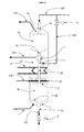
- the invention is illustrated in its basic configuration by the figure 1 .
- the two zones Za and Zb are, according to the invention, successive reaction zones, which means that the effluents from one of these zones supply the other zone without passing through another reaction zone. They are typically separated by a narrowing of the catalyst passage, located at the collection of spent catalyst (typically partially) from Za.
- the invention makes it possible to increase the catalytic activity of the catalyst supplying the zone Zb by adding regenerated and / or fresh catalyst and thus to reduce the disparities in catalytic activity between the reaction zones.
- the device represented in FIG. figure 1 comprises means for withdrawing and discharging (104) a portion of said spent catalyst from the upper reaction zone Za connected to the collection means.
- This makes it possible to eliminate a portion (for example from 10 to 70%, and often from 15 to 50%) of the spent catalyst, before the introduction of regenerated and / or fresh catalyst.
- the average activity of the mixed catalyst feeding Zb is increased, without generally appreciably increasing the total flow rate of catalyst entering Zb, or even keeping the flow rate of circulating catalyst in Za and Zb constant.
- the invention makes it possible to obtain a certain rebalancing of the catalytic activity between the different reaction zones.
- This extra regenerated and / or fresh catalyst can also represent for example from 10 to 70%, and often from 15 to 50% of the catalyst feeding Za at the reactor head, or feeding Zb.
- the two successive reaction zones Za and Zb are connected by a circulation circuit of the reaction fluid passing through a heat exchange means (8), internal or external to said reactor, for example a reheat furnace or a heat exchanger (typically with an auxiliary thermal fluid) for heating or cooling the reaction fluid.
- a heat exchange means (8) is disposed inside the reactor, in an intermediate zone located between the two successive reaction zones Za and Zb. It can advantageously be a heat exchanger disposed in the intermediate zone, at a narrowing of the catalyst passage from zone Za to zone Zb.
- the intermediate zone comprises means for introducing (10) one or more additional reaction fluids (106), and for mixing this or these fluids with the reaction fluid flowing between the successive reaction zones Za and Zb. It may be in particular useful to add a new chemical reagent, to carry out a reaction subsequent to that carried out in the upstream zone, for example an alkylation reaction of an aromatic molecule or a mixture of aromatics, and / or or introducing a hydrogen-rich recycle gas (comprising more than 50% and often more than 70 mol% H 2) to increase the amount of hydrogen present. This gas may also have a thermal effect, reheating or more frequently cooling effluents before they enter the downstream reaction zone.
- the device of the invention and all its variants as described in the present application, can be used especially in the context of a chemical conversion process of hydrocarbons, and in particular of a process for oligomerization of olefinic feeds. having 2 to 12 carbon atoms, this or these method (s) constituting another object of the invention.
- the typical conditions are as follows: the pressure is between 0.1 and 10 MPa and preferably between 0.3 and 7 MPa, the temperature is between 40 and 600 ° C and preferably between 60 and 400 ° C, the hourly space velocity VVH is between 0.01 and 100 h -1 and preferably between 0.4 and 30 h -1 , and the catalyst circulates in each reaction zone at a speed (average) included between 1 cm / hour and 200 cm / hour and preferably between 2 cm / hour and 100 cm / hour.
- the invention is particularly suitable for processes in which the operating conditions are chosen: temperature, pressure, VVH, so as to limit the temperature variation in each of the reaction zones to one or more values between 2 ° C and 50 ° C.
- the catalyst travels all the downstream reaction zones, and the feed also travels all the reaction zones but against the current of the catalyst.
- the reaction zones shown are of the axial reactor type. However, a configuration in which the reaction fluid circulates co-current of the catalyst, ie from top to bottom is also perfectly possible within the scope of the invention. Moreover, the reaction zones can also be of the radial reactor type (and not only of the axial reactor type).
- the fresh and / or regenerated catalyst is fed, mainly in general, at the top of the reactor via the line (102) and then the conduit (2a).
- This catalyst flows slowly, continuously or discontinuously in a zone Za, referenced (3a) on the figure 1 which is the upper reaction zone. In the lower part of this zone, it is collected in a collection zone (4a) and then flows into the chamber (5). A fraction of this catalyst, partially spent, is withdrawn through the conduit (104), typically to be regenerated.
- the chamber (5) may be provided with means (not shown) to facilitate the extraction of a granular product such as catalyst, for example an extraction screw, or a pneumatic transport container, or a fluidized bed or any another means known to those skilled in the art. It is also possible to use a duct (104) inclined at least 60 ° with respect to the horizontal and optionally aeration of catalyst aeration gases (for example nitrogen) to facilitate the removal of the catalyst.
- the non-extracted part of the catalyst present in the chamber (5) flows into the mixing chamber (7), to be mixed with another part of the fresh and / or regenerated catalyst, introduced via the line (103), via the valve (6). It is possible to use a duct (103) inclined at least 60 ° with respect to the horizontal, including in its end part, and optionally injections of aeration gas of the catalyst (for example nitrogen) to facilitate introducing the fresh and / or regenerated catalyst.
- aeration gas of the catalyst for example nitrogen
- the mixing chamber (7) may be provided with means (not shown) to facilitate the mixing of fresh / regenerated catalyst and partially spent catalyst.
- means not shown
- the catalyst mixture thus formed has a catalytic activity increased compared to that of the spent catalyst from zone Za.
- This mixture passes through a narrowing passage (2b), then feeds the zone Zb, referenced (3b) on the figure 1 which is immediately below Za (from the point of view of the reaction zones).
- the spent catalyst from zone Zb (3b) circulates in an extraction pipe (4b) and is then discharged from the reactor via the pipe (105) on which the valve (9) is located. It is then sent to a regeneration zone (not shown) via a particle transport system by means of a liquid or gaseous transport fluid (for example nitrogen), according to well-known technologies. of the person skilled in the art concerning the moving bed. It is particularly possible to use, at the level of the duct (105) or below the valve (9), a spent catalyst recipe for the storage of a predetermined quantity of catalyst before its sequential evacuation by pneumatic transport, by means generally a primary aeration fluid of the catalyst, and a secondary transport fluid.
- a liquid or gaseous transport fluid for example nitrogen
- the regeneration zone of the catalyst may be equipped with an elutriator or any other means for separating the fine particles created during the various catalyst transport operations.
- the regenerated catalyst (after in particular a controlled oxidation of the carbonaceous deposits) is typically recycled through the conduits (102) and (103), with a supplement of fresh catalyst.
- a fraction of the loop catalyst (often spent catalyst) is generally removed to allow the addition of fresh catalyst while keeping the total amount of catalyst employed constant.
- the reaction fluid for example a C4-C6 olefinic hydrocarbon feedstock (having essentially from 4 to 6 carbon atoms), is fed via line (100) into feed chamber 1, passes through reaction zone Zb ( 3b) filled with catalyst, then the intermediate zone (22) containing no catalyst, then enters the catalyst-filled reaction zone Za (3a), then enters the chamber (23) before being discharged through the conduit ( 101).
- the reaction zones Za and Zb are advantageously provided at the top and bottom of perforated grids (shown in dotted lines in the figures) to allow the passage of the reaction fluid. These grids can be inclined at an angle of 60 ° or more, at the bottom, to facilitate the flow of the catalyst.
- a heat exchanger (8) with a thermal fluid circulation is placed inside the reactor, in the intermediate zone (22) (itself located inside the reactor), in order to carry out a heat exchange with the reaction fluid between Zb and Za.
- This heat exchanger is advantageously arranged at the level of the narrowing 2b of the catalyst passage, because of the space thus released inside the reactor.
- This heat exchanger generally uses a heating or cooling fluid circulating inside tubes, the set of tubes forming for example one or more pins dipping within the reaction fluid in the intermediate zone (22).
- the exchanger may however be of any type known to those skilled in the art, the invention being in no way related to the particular technology of this exchanger.
- heating or cooling fluid water vapor, air, water, hydrogen or hydrogen-rich recycle gas, nitrogen, molten salts, aromatic oil, etc.
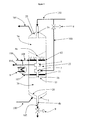
- the figure (2 ) represents another reaction device according to the present invention, comprising the same elements as those of the device of the figure 1 . It further comprises a conduit (106) for supplying an additional reaction fluid, for additional reagent and / or a supplement of hydrogen. this fluid is distributed in the intermediate zone (22) via a distribution manifold (10) to facilitate its homogeneous mixing with the reaction fluid resulting from the zone Zb. The mixture is also favored by the fact that the intermediate zone (22) is free of catalyst.
- the reaction device comprises a heat exchanger (8) which is external to the reactor.
- the reaction fluid from the zone Zb is collected via the conduit (11), feeds the exchanger (8), and is then reintroduced into the reactor, after addition of the additional reaction fluid, via the conduit (108) and the distribution manifold (12), which are also part of the reaction device.
- the flow rate of the regenerated catalyst booster, or possibly fresh catalyst is defined so as to maintain a determined level of activity on each reaction zone.
- this catalyst make-up rate is defined as a function of a characteristic of the reaction fluid at the outlet of the reaction zone. This characteristic can be a temperature, a composition, a conversion, or any other measurable physico-chemical characteristic in line. Correlations that relate one or more of these in-line measurable quantities to the activity level of the catalyst depend on the reaction employed, the type of catalyst and its circulation rate.
- a simple way is notably to control the conversion in zone Zb, or the temperature variation (delta T) of the reaction fluid in this zone, or the exit temperature of this zone, by acting on the catalyst make-up flow rate.
- regenerated and / or fresh If the measured value of the delta T is lower than the expected value (typically depending on the initial composition of the charge), or if the value of the outlet temperature of the zone corresponds to an insufficient reaction, then increases the regenerated and / or new catalyst make-up flow rate in this zone, and conversely the make-up is reduced if the conversion in the zone (deduced from the delta T or from the outlet temperature) is too great.
- the same amount of used catalyst can be removed as that of the catalyst booster, before mixing, to keep constant the overall flow of catalyst in the zone Zb.
- the flow rate of makeup catalyst can therefore be fully automated. Alternatively, it can be adjusted at certain times (for example once or twice a day) by the operator, especially in view of the temperatures and / or delta T above.
- Reheating or cooling of the reaction fluid in the exchanger (8) can be controlled by, in particular, the flow rate or the temperature level of the thermal fluid circulating in the exchanger (8).
- the devices of figures 2 and 3 operate in a similar way. In these devices a supplement of reagents and / or hydrogen supplied by the conduit (106) is used. This booster is typically controlled flow and temperature.
- the catalyst flowing in the reaction device according to the invention can be of various types.
- an oligomerization reaction device it is possible to use, in particular, any type of acidic catalyst that enables oligomerization, for example an amorphous silica-alumina or solid phosphoric acid type or ion exchange resin type catalyst. or a catalyst having a shape selectivity, for example a zeolite catalyst, for example a zeolite catalyst of structural type MFI, FER, EUO, TON, LTL, MOR, MTT, MEL, MWW, MTW or zeolites NU-86 , NU-87, NU-88, IM-5.
- a zeolite catalyst for example a zeolite catalyst of structural type MFI, FER, EUO, TON, LTL, MOR, MTT, MEL, MWW, MTW or zeolites NU-86 , NU-87, NU-88, IM-5.
- zeolitic acid catalysts may be used in the state or after modifications, the said modifications preferably affecting the acidity of the catalyst, the term acidity denoting as well the strength of acidic sites as the concentration of acidic sites.
- modifications can affect the framework of the zeolite, for example if it is a dealumination by vapotraitement or by acid treatment, and / or affect the surface of the zeolite, for example (i) by proton exchanges by alkaline type cations, (ii) inert phase deposits on the surface of the zeolites.
- the device according to the invention is particularly suitable for olefin oligomerization reactions, but it can be more generally used for any type of exothermic or endothermic reaction, taking place in the gas phase and / or liquid, and for which a fine control the temperature profile in each reaction zone is necessary, in particular the reactions of addition of one olefin to another compound present in the feedstock, for example an olefin, a sulfur compound, a nitrogen compound, an aromatic molecule, said reactions of addition to increase the molecular weight of this compound, in particular the alkylation reactions of thiophene compounds with olefins, the metathesis of olefins.
- the device according to the invention can also be used for skeletal isomerization reactions of light olefins such as, for example, olefins with 4 or 5 carbon atoms.
- the cooling thermal fluid can be any fluid adapted to perform the heat exchange under good conditions, in particular by respecting an average temperature difference between the reaction fluid and the cooling fluid of at least 5 ° C and preferably at least 10 ° C.
- the invention is in no way related to a particular cooling or heating fluid.
- Examples 1, 3 and 5 are according to the prior art.
- Examples 2, 4 and 6 are according to the invention, and are respectively associated with Examples 1, 3 and 5 to highlight the effect of the device according to the invention with respect to a fixed bed implementation.
- This example relates to the oligomerization reaction of a fixed bed C3 unsaturated cut.
- a dealuminated zeolite mordenite catalyst having a Si / Al molar ratio of 57 was tested for the oligomerization reaction of propene, after forming into beads with an alumina binder.
- the reaction is carried out in a conventional fixed bed reactor.
- the catalyst used is shaped into spherical beads 3 mm in diameter.
- the feed used for this test is a steam cracker feed which contains 94% by weight of propene and 6% by weight of propane.
- the conditions were chosen so as to optimize the formation of the diesel fraction in the oligomer product.
- Table 1 zeolite MOR Si / Al molar ratio 57 Ball composition 20% by weight Al 2 O 3 /80% by weight zeolite Reactor inlet temperature (° C) 210 Reactor outlet temperature (° C) at the beginning of the test 247 Deactivation of catalyst (% conversion lost per day) 1.4 Oligomer C5 + (% wt) 83.3 Diesel cut (> 180 ° C,% weight) 77.6 Engine cetane number * 38 after hydrogenation
- Example 2 corresponds to the same reaction as that of Example 1, using the same catalyst used in a reaction device according to the invention, such as that of figure 1 .
- the reactor comprises two reaction zones denoted Zb (initial zone (3b)) and Za (final zone (3a)), in series, separated by an intermediate zone comprising a water cooling system constituting the heat exchanger.
- the charge, the test conditions and the catalyst are the same as for example 1.
- the charge and the catalyst circulate in countercurrent.
- VVH volume flow rate of charge per volume of catalyst
- 20% of the spent catalyst from the upper reaction zone is withdrawn, which is replaced by regenerated catalyst in the same amount, to increase the catalytic activity in the lower reaction zone.
- the coolant temperature is set so that the reaction temperature at the inlet of the second reaction zone is 210 ° C.
- the cooling fluid used is water introduced at 25 ° C.
- Example 3 consists of an oligomerization reaction of an unsaturated C4 cut carried out in a fixed bed.
- the catalyst used is in the form of spherical beads 3 mm in diameter.
- This dealuminized zeolite mordenite catalyst having a Si / Al molar ratio of 57 is used for the oligomerization reaction of a slice containing 60% by weight of unsaturated butene, 3% by weight of iso-butene, 11% by weight of n-butanol. butane and 26% by weight of isobutane.
- the reaction is conducted in a conventional fixed bed reactor.
- the conditions were chosen so as to optimize the formation of the diesel fraction in the oligomer product.
- the operating conditions are as follows: Reactor inlet charge temperature 210 ° C Pressure 6.0 MPa VVH 1.0 h -1
- VVH volume flow rate of charge per volume of catalyst
- Table 3 zeolite MOR Si / Al molar ratio 57 Ball composition 40% wtAl 2 O 3 /60% w zeolite Reactor inlet temperature (° C) 210 Reactor outlet temperature (° C) at the beginning of the test 233 Deactivation of catalyst (% conversion lost per day) 0.9 Diesel cut (> 180 ° C,% weight) 83.6 Engine cetane number * 40 after hydrogenation
- Example 4 consists of carrying out the same reaction as that of Example 3 in a reaction device according to the invention, such as that of figure 1 , using the same catalyst.
- the reaction is carried out in a reactor comprising two reaction zones in series, denoted Zb (initial zone (3b)) and Za (final zone (3a)), separated by an intermediate zone comprising a water cooling system constituting the heat exchanger. .
- the charge, the test conditions and the catalyst are the same as for example 3.
- VVH volume flow rate of charge per volume of catalyst
- 20% of the spent catalyst from the upper reaction zone is withdrawn, which is replaced by regenerated catalyst in the same amount, to increase the catalytic activity in the lower reaction zone.
- the coolant temperature (water at 25 ° C) is set so that the reaction temperature at the inlet of the second reaction zone is 210 ° C.
- Example 5 consists of carrying out the oligomerization reaction of an unsaturated C6 cut using a dealuminated zeolite mordenite catalyst having a Si / Al molar ratio of 57. This catalyst is used in the form of spherical beads. 3 mm in diameter. The reaction is carried out in a conventional fixed bed reactor.
- the feed used for this test contains 72% by weight olefinic unsaturated C6, 7% by weight unsaturated paraffinic C6, 18% olefinic unsaturated C9, 3% olefinic unsaturated C12.
- the conditions were chosen so as to optimize the formation of the diesel fraction in the oligomer product.
- the operating conditions are as follows: Reactor inlet charge temperature 230 ° C Pressure 6.0 MPa VVH 1 h -1
- VVH volume flow rate of charge per volume of catalyst
- Example 6 consists of carrying out the same reaction as that of Example 5 in a reaction device according to the invention, such as that of figure 1 .
- the reaction is carried out in a reactor comprising two series reaction zones marked Zb (initial zone (3b)) and Za (final zone (3a)), separated by an intermediate zone comprising a water cooling system constituting the heat exchanger.
- VVH volume flow rate of charge per volume of catalyst
- 20% of the spent catalyst from the upper reaction zone is withdrawn, which is replaced by regenerated catalyst in the same amount, to increase the catalytic activity in the lower reaction zone.
- the coolant temperature is set so that the reaction temperature at the inlet of the second reaction zone is 230 ° C.
- the cooling fluid is water at 25 ° C.
- Table 6 zeolite MOR Si / Al molar ratio 57 Temperature input reaction zone Zb (° C) 230 Reaction zone exit temperature Zb (° C) 238 Temperature input reaction zone Za (° C) 230 Reaction zone exit temperature Za (° C) 235 Diesel cut (> 180 ° C,% weight) 65.4 Engine cetane number * 43 after hydrogenation
Landscapes
- Chemical & Material Sciences (AREA)
- Organic Chemistry (AREA)
- Chemical Kinetics & Catalysis (AREA)
- Oil, Petroleum & Natural Gas (AREA)
- Engineering & Computer Science (AREA)
- General Chemical & Material Sciences (AREA)
- Organic Low-Molecular-Weight Compounds And Preparation Thereof (AREA)
- Production Of Liquid Hydrocarbon Mixture For Refining Petroleum (AREA)
- Devices And Processes Conducted In The Presence Of Fluids And Solid Particles (AREA)
- Catalysts (AREA)
- Physical Or Chemical Processes And Apparatus (AREA)
Applications Claiming Priority (2)
| Application Number | Priority Date | Filing Date | Title |
|---|---|---|---|
| FR0411961A FR2877590B1 (fr) | 2004-11-09 | 2004-11-09 | Dispositif reactionnel a plusieurs zones en lit mobile avec appoint dans chaque zone de catalyseur regenere ou frais |
| PCT/FR2005/002721 WO2006051185A1 (fr) | 2004-11-09 | 2005-10-28 | Dispositif reactionnel a plusieurs zones en lit mobile avec appoint dans chaque zone de catalyseur regenere ou frais |
Publications (2)
| Publication Number | Publication Date |
|---|---|
| EP1814654A1 EP1814654A1 (fr) | 2007-08-08 |
| EP1814654B1 true EP1814654B1 (fr) | 2015-07-29 |
Family
ID=34952525
Family Applications (1)
| Application Number | Title | Priority Date | Filing Date |
|---|---|---|---|
| EP05815267.9A Ceased EP1814654B1 (fr) | 2004-11-09 | 2005-10-28 | Dispositif reactionnel a plusieurs zones en lit mobile avec appoint dans chaque zone de catalyseur regenere ou frais |
Country Status (7)
| Country | Link |
|---|---|
| US (1) | US7611678B2 (enExample) |
| EP (1) | EP1814654B1 (enExample) |
| JP (1) | JP5235414B2 (enExample) |
| KR (1) | KR101240836B1 (enExample) |
| CN (1) | CN101163541B (enExample) |
| FR (1) | FR2877590B1 (enExample) |
| WO (1) | WO2006051185A1 (enExample) |
Families Citing this family (18)
| Publication number | Priority date | Publication date | Assignee | Title |
|---|---|---|---|---|
| FR2877589B1 (fr) * | 2004-11-09 | 2007-01-12 | Inst Francais Du Petrole | Reacteur a plusieurs zones en lit fixe ou mobile avec echangeur thermique integre |
| DE102009004750A1 (de) * | 2009-01-15 | 2010-09-02 | Highterm Research Gmbh | Reaktor und Verfahren zur Aufbereitung eines Eduktgases zu einem Produktgas |
| DE102009019436A1 (de) | 2009-04-29 | 2010-11-04 | Bayer Materialscience Ag | Verfahren zur Herstellung von aromatischen Aminen |
| DE102009039276A1 (de) | 2009-08-28 | 2011-03-10 | Bekon Energy Technologies Gmbh & Co. Kg | Reaktormodul für endotherme Reaktionen sowie Reaktor mit einer Mehrzahl von solchen Reaktormodulen |
| US20130224104A1 (en) | 2010-09-03 | 2013-08-29 | Greg Naterer | Heat Exchanger Using Non-Pure Water for Steam Generation |
| US9732285B2 (en) | 2013-12-17 | 2017-08-15 | Uop Llc | Process for oligomerization of gasoline to make diesel |
| US9670425B2 (en) | 2013-12-17 | 2017-06-06 | Uop Llc | Process for oligomerizing and cracking to make propylene and aromatics |
| WO2016054788A1 (en) | 2014-10-09 | 2016-04-14 | Basf Se | A process for the production of oligomerized olefins |
| CN107109243A (zh) * | 2014-11-14 | 2017-08-29 | 赛贝克环球科技公司 | 多级反应器及其相关方法 |
| CN106140033B (zh) * | 2015-04-02 | 2018-07-06 | 中石化广州工程有限公司 | 一种催化剂的添加方法 |
| WO2017003784A1 (en) * | 2015-06-30 | 2017-01-05 | Uop Llc | Reactor and heater configuration synergies in paraffin dehydrogenation process |
| US10563135B2 (en) | 2015-12-04 | 2020-02-18 | Uop Llc | Process for producing a diesel fuel by oligomerization |
| US10814316B2 (en) | 2016-12-15 | 2020-10-27 | Shell Oil Company | Catalytic process for co-production of benzene, ethylene, and hydrogen |
| US11414362B2 (en) * | 2018-03-23 | 2022-08-16 | Exxonmobil Chemical Patents Inc. | Processes and systems for the conversion of hydrocarbons |
| CN115025721B (zh) * | 2021-04-30 | 2024-06-21 | 青岛京润石化工程有限公司 | 一种催化剂连续循环反应实验装置 |
| CN115722151B (zh) * | 2021-08-31 | 2024-11-29 | 中国石油化工股份有限公司 | 一种固-液移动床反应器、反应系统及其应用 |
| CN114950281B (zh) * | 2022-06-13 | 2023-09-22 | 清华大学 | 一种高效裂解c3-c9非芳烃制备芳烃的系统与方法 |
| US20250313760A1 (en) * | 2024-04-04 | 2025-10-09 | Chevron U.S.A. Inc. | Radial flow moving bed reactor for catalytic cracking of light hydrocarbons |
Family Cites Families (17)
| Publication number | Priority date | Publication date | Assignee | Title |
|---|---|---|---|---|
| US2376365A (en) * | 1942-03-26 | 1945-05-22 | Houdry Process Corp | Apparatus for effecting contacting reactions |
| US2336041A (en) * | 1943-04-28 | 1943-12-07 | Socony Vacuum Oil Co Inc | Method for catalytic conversion |
| US2463912A (en) * | 1946-12-12 | 1949-03-08 | Standard Oil Dev Co | Synthesis of hydrocarbons |
| FR1041780A (fr) * | 1950-05-11 | 1953-10-27 | Procédé et installation pour le chauffage des combustibles et des matières analogues | |
| DE1028095B (de) * | 1952-09-13 | 1958-04-17 | Metallgesellschaft Ag | Verfahren zum Erhitzen von feinkoernigen, insbesondere wasserhaltigen Stoffen mittels fester Waermetraeger |
| NL168717C (nl) * | 1970-04-21 | Ube Industries | Inrichting voor het overdragen van warmte tussen een eerste en een tweede gas met toepassing van een in kringloop gevoerde, fijnverdeelde vaste stof als warmte-overdrachtsmiddel. | |
| FR2129913A1 (en) * | 1971-03-19 | 1972-11-03 | Inst Francais Du Petrole | Hydrocarbon conversion with continuous catalyst replacement - and continuous control of heat supply |
| US3799866A (en) * | 1972-10-18 | 1974-03-26 | Universal Oil Prod Co | Hydrocarbon conversion process utilizing a moving bed reactor |
| JPS59160531A (ja) * | 1983-03-01 | 1984-09-11 | Nippon Oil Co Ltd | 粒体の加熱処理方法およびその装置 |
| ES2074550T3 (es) * | 1989-01-13 | 1995-09-16 | Inst Francais Du Petrole | Procedimiento de regeneracion de un catalizador de produccion de hidrocarburos aromaticos o de reformacion. |
| CN1023077C (zh) * | 1989-01-13 | 1993-12-15 | 法国石油公司 | 芳香烃制备或重整催化剂的再生方法 |
| EP0602287B1 (en) * | 1992-12-18 | 1997-03-05 | Shell Internationale Researchmaatschappij B.V. | Reactor for catalytic processes |
| DE69806435T2 (de) * | 1997-04-14 | 2002-11-07 | Institut Francais Du Petrole, Rueil-Malmaison | Verfahren und Gehäuse für die Regenerierung eines Katalysators mit Kontrolle des Endes des Verbrennungsprozesses |
| FR2788448B1 (fr) * | 1999-01-19 | 2001-03-16 | Claude Roux | Systeme de neutralisation de gaz polluants par pyrolyse |
| FR2821283B1 (fr) * | 2001-02-28 | 2003-04-18 | Inst Francais Du Petrole | Procede et reacteur multi-etages catalytique a faible epaisseur avec echangeur thermique interne, et son utilisation |
| FR2837199B1 (fr) * | 2002-03-15 | 2005-09-16 | Inst Francais Du Petrole | Procede de conversion en plusieurs etapes d'une charge comprenant des olefines a quatre, cinq atomes de carbone ou plus, en vue de produire du propylene |
| CN1194073C (zh) * | 2002-07-17 | 2005-03-23 | 清华大学 | 利用下行床反应器进行烃类催化热裂解的方法 |
-
2004
- 2004-11-09 FR FR0411961A patent/FR2877590B1/fr not_active Expired - Fee Related
-
2005
- 2005-10-28 JP JP2007540670A patent/JP5235414B2/ja not_active Expired - Lifetime
- 2005-10-28 KR KR1020077012962A patent/KR101240836B1/ko not_active Expired - Fee Related
- 2005-10-28 EP EP05815267.9A patent/EP1814654B1/fr not_active Ceased
- 2005-10-28 WO PCT/FR2005/002721 patent/WO2006051185A1/fr not_active Ceased
- 2005-10-28 CN CN200580046232XA patent/CN101163541B/zh not_active Expired - Fee Related
- 2005-11-09 US US11/269,883 patent/US7611678B2/en not_active Expired - Fee Related
Also Published As
| Publication number | Publication date |
|---|---|
| CN101163541A (zh) | 2008-04-16 |
| US20060122446A1 (en) | 2006-06-08 |
| KR101240836B1 (ko) | 2013-03-07 |
| CN101163541B (zh) | 2012-12-26 |
| JP5235414B2 (ja) | 2013-07-10 |
| WO2006051185A1 (fr) | 2006-05-18 |
| FR2877590B1 (fr) | 2007-01-12 |
| KR20070100881A (ko) | 2007-10-12 |
| EP1814654A1 (fr) | 2007-08-08 |
| JP2008518782A (ja) | 2008-06-05 |
| FR2877590A1 (fr) | 2006-05-12 |
| US7611678B2 (en) | 2009-11-03 |
Similar Documents
| Publication | Publication Date | Title |
|---|---|---|
| EP1814654B1 (fr) | Dispositif reactionnel a plusieurs zones en lit mobile avec appoint dans chaque zone de catalyseur regenere ou frais | |
| EP1661617B1 (fr) | Réacteur à plusieurs zones en lit fixe ou mobile avec echangeur thermique intégré | |
| EP2468838B1 (fr) | Production de carburants paraffiniques à partir de matières renouvelables par un procédé d'hydrotraitement en continu | |
| EP0820806B1 (fr) | Procédé pour le fonctionnement d'une colonne à bulles triphasique avec application en synthèse fischer-tropsch | |
| FR2802211A1 (fr) | Procede et dispositif de craquage catalytique comprenant en parallele au moins un reacteur a ecoulement ascendant et au moins un reacteur a ecoulement descendant | |
| EP1800742A1 (fr) | Réacteur à deux zones réactionnelles fluidisées avec système de séparation gaz/solide intégré | |
| WO2009007519A2 (fr) | Zone réactionnelle comportant deux risers en parallèle et une zone de séparation gaz solide commune en vue de la production de propylène | |
| FR2953851A1 (fr) | Procede de craquage catalytique avec maximisation des bases gazoles | |
| EP2627736B1 (fr) | Procede de craquage et de stripage multi-etage dans une unite de fcc. | |
| EP1131389B1 (fr) | Procede et dispositif de craquage catalytique comprenant des reacteurs a ecoulements descendant et ascendant | |
| EP1637575B1 (fr) | Procédé de production de propylène fonctionnant en lit mobile avec recyclage d'une fraction de catalyseur usé | |
| FR3053355B1 (fr) | Procede d'oligomerisation utilisant un catalyseur zeolithique et un catalyseur comprenant une silice alumine | |
| EP3173460B1 (fr) | Procédé d'oligomérisation d'oléfines légères au moyen d'une section réactionnelle comprenant trois réacteurs permutables favorisant la sélectivité vers les distillats | |
| EP1110931B1 (fr) | Procédé et dispositif pour l'alkylation de l'isobutane par des oléfines légères. | |
| FR2890077A1 (fr) | Procede de desulfuration d'essences olefiniques par alourdissement des composes soufres avec regeneration du catalyseur | |
| US11958046B1 (en) | Methods and systems for alkylate production involving a multi-zone alkylation reactor | |
| RU2823585C2 (ru) | Преобразование сырой нефти в псевдоожиженном слое, содержащем зоны с разным временем контакта | |
| FR3135264A1 (fr) | Procédé de fabrication d’un carburéacteur, carburéacteur et installation associés | |
| FR2462471A1 (fr) | Procede de reformage catalytique a usages multiples utilisant des particules de catalyseur dissemblables qui s'ecoulent par gravite | |
| BE555767A (enExample) |
Legal Events
| Date | Code | Title | Description |
|---|---|---|---|
| PUAI | Public reference made under article 153(3) epc to a published international application that has entered the european phase |
Free format text: ORIGINAL CODE: 0009012 |
|
| 17P | Request for examination filed |
Effective date: 20070611 |
|
| AK | Designated contracting states |
Kind code of ref document: A1 Designated state(s): DE ES FR GB IT NL |
|
| DAX | Request for extension of the european patent (deleted) | ||
| RBV | Designated contracting states (corrected) |
Designated state(s): DE ES FR GB IT NL |
|
| 17Q | First examination report despatched |
Effective date: 20100203 |
|
| GRAP | Despatch of communication of intention to grant a patent |
Free format text: ORIGINAL CODE: EPIDOSNIGR1 |
|
| INTG | Intention to grant announced |
Effective date: 20150305 |
|
| GRAS | Grant fee paid |
Free format text: ORIGINAL CODE: EPIDOSNIGR3 |
|
| GRAA | (expected) grant |
Free format text: ORIGINAL CODE: 0009210 |
|
| AK | Designated contracting states |
Kind code of ref document: B1 Designated state(s): DE ES FR GB IT NL |
|
| REG | Reference to a national code |
Ref country code: GB Ref legal event code: FG4D Free format text: NOT ENGLISH |
|
| REG | Reference to a national code |
Ref country code: DE Ref legal event code: R096 Ref document number: 602005047113 Country of ref document: DE |
|
| REG | Reference to a national code |
Ref country code: FR Ref legal event code: PLFP Year of fee payment: 11 |
|
| REG | Reference to a national code |
Ref country code: NL Ref legal event code: FP |
|
| PG25 | Lapsed in a contracting state [announced via postgrant information from national office to epo] |
Ref country code: ES Free format text: LAPSE BECAUSE OF FAILURE TO SUBMIT A TRANSLATION OF THE DESCRIPTION OR TO PAY THE FEE WITHIN THE PRESCRIBED TIME-LIMIT Effective date: 20150729 |
|
| PG25 | Lapsed in a contracting state [announced via postgrant information from national office to epo] |
Ref country code: IT Free format text: LAPSE BECAUSE OF FAILURE TO SUBMIT A TRANSLATION OF THE DESCRIPTION OR TO PAY THE FEE WITHIN THE PRESCRIBED TIME-LIMIT Effective date: 20150729 |
|
| REG | Reference to a national code |
Ref country code: DE Ref legal event code: R097 Ref document number: 602005047113 Country of ref document: DE |
|
| REG | Reference to a national code |
Ref country code: DE Ref legal event code: R119 Ref document number: 602005047113 Country of ref document: DE |
|
| PLBE | No opposition filed within time limit |
Free format text: ORIGINAL CODE: 0009261 |
|
| STAA | Information on the status of an ep patent application or granted ep patent |
Free format text: STATUS: NO OPPOSITION FILED WITHIN TIME LIMIT |
|
| 26N | No opposition filed |
Effective date: 20160502 |
|
| PG25 | Lapsed in a contracting state [announced via postgrant information from national office to epo] |
Ref country code: DE Free format text: LAPSE BECAUSE OF NON-PAYMENT OF DUE FEES Effective date: 20160503 |
|
| REG | Reference to a national code |
Ref country code: FR Ref legal event code: PLFP Year of fee payment: 12 |
|
| REG | Reference to a national code |
Ref country code: FR Ref legal event code: PLFP Year of fee payment: 13 |
|
| REG | Reference to a national code |
Ref country code: FR Ref legal event code: PLFP Year of fee payment: 14 |
|
| PGFP | Annual fee paid to national office [announced via postgrant information from national office to epo] |
Ref country code: NL Payment date: 20201027 Year of fee payment: 16 |
|
| PGFP | Annual fee paid to national office [announced via postgrant information from national office to epo] |
Ref country code: FR Payment date: 20201027 Year of fee payment: 16 Ref country code: GB Payment date: 20201027 Year of fee payment: 16 |
|
| REG | Reference to a national code |
Ref country code: NL Ref legal event code: MM Effective date: 20211101 |
|
| GBPC | Gb: european patent ceased through non-payment of renewal fee |
Effective date: 20211028 |
|
| PG25 | Lapsed in a contracting state [announced via postgrant information from national office to epo] |
Ref country code: NL Free format text: LAPSE BECAUSE OF NON-PAYMENT OF DUE FEES Effective date: 20211101 Ref country code: GB Free format text: LAPSE BECAUSE OF NON-PAYMENT OF DUE FEES Effective date: 20211028 |
|
| PG25 | Lapsed in a contracting state [announced via postgrant information from national office to epo] |
Ref country code: FR Free format text: LAPSE BECAUSE OF NON-PAYMENT OF DUE FEES Effective date: 20211031 |