EP1813537A2 - Boîtier d'accommodation de cartouche - Google Patents
Boîtier d'accommodation de cartouche Download PDFInfo
- Publication number
- EP1813537A2 EP1813537A2 EP07001310A EP07001310A EP1813537A2 EP 1813537 A2 EP1813537 A2 EP 1813537A2 EP 07001310 A EP07001310 A EP 07001310A EP 07001310 A EP07001310 A EP 07001310A EP 1813537 A2 EP1813537 A2 EP 1813537A2
- Authority
- EP
- European Patent Office
- Prior art keywords
- case
- cartridges
- accommodation
- cartridge
- impact
- Prior art date
- Legal status (The legal status is an assumption and is not a legal conclusion. Google has not performed a legal analysis and makes no representation as to the accuracy of the status listed.)
- Withdrawn
Links
- 238000005192 partition Methods 0.000 claims abstract description 37
- 239000000088 plastic resin Substances 0.000 claims description 18
- -1 polyethylene terephthalate Polymers 0.000 claims description 8
- 239000004793 Polystyrene Substances 0.000 claims description 6
- 229920002223 polystyrene Polymers 0.000 claims description 5
- 239000004743 Polypropylene Substances 0.000 claims description 4
- 239000005020 polyethylene terephthalate Substances 0.000 claims description 4
- 229920000139 polyethylene terephthalate Polymers 0.000 claims description 4
- 229920001155 polypropylene Polymers 0.000 claims description 4
- 230000004308 accommodation Effects 0.000 description 82
- 239000000463 material Substances 0.000 description 8
- 238000004804 winding Methods 0.000 description 5
- 230000015572 biosynthetic process Effects 0.000 description 4
- 238000000034 method Methods 0.000 description 4
- 238000010521 absorption reaction Methods 0.000 description 3
- XLYOFNOQVPJJNP-UHFFFAOYSA-N water Substances O XLYOFNOQVPJJNP-UHFFFAOYSA-N 0.000 description 3
- 230000001419 dependent effect Effects 0.000 description 2
- 230000000694 effects Effects 0.000 description 2
- 239000002184 metal Substances 0.000 description 2
- 239000011347 resin Substances 0.000 description 2
- 229920005989 resin Polymers 0.000 description 2
- 238000007666 vacuum forming Methods 0.000 description 2
- TVEXGJYMHHTVKP-UHFFFAOYSA-N 6-oxabicyclo[3.2.1]oct-3-en-7-one Chemical compound C1C2C(=O)OC1C=CC2 TVEXGJYMHHTVKP-UHFFFAOYSA-N 0.000 description 1
- 238000005452 bending Methods 0.000 description 1
- 230000037237 body shape Effects 0.000 description 1
- 230000003139 buffering effect Effects 0.000 description 1
- 238000010586 diagram Methods 0.000 description 1
- 239000000428 dust Substances 0.000 description 1
- 238000012856 packing Methods 0.000 description 1
- 239000004033 plastic Substances 0.000 description 1
- 229920003023 plastic Polymers 0.000 description 1
- 238000004904 shortening Methods 0.000 description 1
- 238000000638 solvent extraction Methods 0.000 description 1
- 239000000126 substance Substances 0.000 description 1
- 239000002699 waste material Substances 0.000 description 1
Images


Classifications
-
- G—PHYSICS
- G11—INFORMATION STORAGE
- G11B—INFORMATION STORAGE BASED ON RELATIVE MOVEMENT BETWEEN RECORD CARRIER AND TRANSDUCER
- G11B23/00—Record carriers not specific to the method of recording or reproducing; Accessories, e.g. containers, specially adapted for co-operation with the recording or reproducing apparatus ; Intermediate mediums; Apparatus or processes specially adapted for their manufacture
- G11B23/02—Containers; Storing means both adapted to cooperate with the recording or reproducing means
- G11B23/023—Containers for magazines or cassettes
- G11B23/0236—Containers for several cassettes
Definitions
- the present invention relates to a cartridge accommodation case for accommodating (flat-body-shaped) cartridges each of which incorporates a magnetic tape reel. More particularly, the invention relates to an improved technique which increases the resistance to impact on the accommodated cartridges as well as the efficiency of the work of housing cartridges.
- Non-patent document (“LTO-Ultrium L-pack", [online], TDK Corp., Internet ⁇ URL: http://www.tdk.com/professional/lto/ltolpack.html>) discloses a plastic case 7 shown in Fig. 5 which is transparent (the contents are seen through it) and is not reduced in case strength even if water sticks to it.
- the case 7 has come to be marketed.
- Fig. 5 shows the case 7 disclosed in the above-mentioned Non-patent document.
- accommodation spaces 9 for housing individual cartridges 1 are defined by plural partitioning projections 11 and one cartridge 1 is stored in each accommodation space 9. That is, the cartridges 1 are accommodated discretely. Therefore, in actual housing work, cartridges 1 are put into the case 7 one by one, which is inconvenient particularly in the case where a large number of cartridges 1 need to be stored.
- the whole accommodation area i.e., the top opening area of the case 7
- the whole accommodation area i.e., the top opening area of the case 7
- the weight of almost all cartridges 1 is concentrated on end case portions 13 and 15. This raises a problem that the case 7 is low in the resistance to impact and hence in the ability to absorb impact when the case 7 is dropped.
- the cartridge 1 is vulnerable to impact that is exerted on it in the axial direction of a magnetic tape reel 1a, for the following reason. There may occur a case that a portion of a magnetic tape 1b wound around the magnetic tape reel 1a projects from the side surface of the magnetic tape 1b. If a tape edge of the projected portion of the magnetic tape 1b hits a flange 1c of the magnetic tape reel 1a, the projected portion may be crushed or bent to obstruct smooth rewinding and paying-out of the magnetic tape 1b. In the worst case, reading and writing are disabled.
- the present invention has been made in view of the above circumstances, and an object of the invention is therefore to provide a cartridge accommodation case capable of realizing high efficiency of housing work and assuring the quality of cartridges by securing sufficient resistance to impact.
- this cartridge accommodation case is formed by drawing a plastic resin sheet of 0.5 to 2.0 mm in thickness, minimum necessary structure-dependent strength of the partitioned rooms for accommodating plural cartridge groups can be secured economically and the weight of the entire accommodation case can be minimized while its minimum necessary strength is satisfied.
- the accommodation case is formed by working on a sheet of the above thickness, a proper degree of deformation can be caused in the accommodation case when external force is applied to it.
- Optimum impact absorbing action for the accommodated cartridges canbe realized. That is, if a sheet used is unduly thin, deformation is caused too easily and the impact absorbing effect is lowered. On the other hand, a sheet used is unduly thick, deformation is not caused easily and impact is transmitted directly to the cartridges.
- This configuration enables formation of optimum impact absorbing portions (crushable zones) by setting the thickness of a plastic resin sheet in the above-mentioned range.
- the partitions absorb part of the impact and thereby prevent the magnetic tapes from hitting the flanges of the magnetic tape reels.
- the quality of the cartridges can thus be assured.
- the accommodation case is produced by performing integral forming on a plastic resin and one partition is projected inward by forming at the prescribed height. Therefore, the accommodation case is given a certain degree of elasticity along this partition and this partition can make some contribution to absorption of external impact. As such, the accommodation case can hold the magnetic cartridges in the prescribed winding state and thereby assure the quality of the cartridges. Still further, since in a partition forming process the degree of drawing in the side walls of the accommodation case is set equal to the prescribed value corresponding to desired case elasticity, the optimum degree of drawing can balance the rigidity and the impact absorbing ability of the accommodation case.
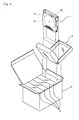
- Fig. 1 is an exploded perspective view of the cartridge accommodation case according to the invention being separated into a top case and a bottom case.
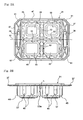
- Figs. 2A and 2B are a plan view and a side view, respectively, of the bottom case shown in Fig. 1.
- Fig. 3 is a perspective view of the cartridge accommodation case of Fig. 1 in a state that the top case and the bottom case are combined together.
- the cartridge accommodation case 100 (hereinafter also referred to simply as "accommodation case") 100 according to the embodiment can be used suitably for housing flat-body-shaped cartridges 27 each of which incorporates a magnetic tape reel 25 in which a magnetic tape 21 is wound inside a pair of flanges 23.
- Each cartridge 27 incorporates the magnetic tape reel 25 in such a manner that its axial direction coincides with the thickness direction of the cartridge 27.
- each cartridge 27 may have other shapes such as a rectangular flat body shape.
- the accommodation case 100 can be opened and closed because a top case 29 and a bottom case 31 having the same structure are placed one on the other and engaged with each other.
- Plural partitioned rooms 33 are formed inside by engaging the top case 29 and the bottom case 31 with each other.
- each of the top case 29 and the bottom case 31 is an integral formed body of a plastic resin. In this manner, the top case 29 and the bottom case 31 which are strong enough to protect the cartridges 27 reliably and have a proper impact absorbing ability can be mass-produced easily at a low cost by using a material that can be handled relatively easily.
- each partitioned room 33 can hold a cartridge group 35 in which plural cartridges 27 are arranged side by side in their thickness direction so as to assume a block form.
- cartridges 27 are oriented in such a manner that their tape access mouths, which are low is strength, are located sideways so as to be adjacent to the center lines of the accommodation case 100. It is even preferable that the tape access mouths of a cartridge group 35 accommodated in one partitioned room 33 be opposed to the tape access mouths of a cartridge group 35 accommodated in another partitioned room 33. In this case, the tape access mouths are located adjacent to the one center line of the accommodation case 100 and can be protected from impact coming from outside the accommodation case 100.
- each partitioned room 33 is approximately equal to the volume of a cartridge group 35 consisting of five cartridges 27. Therefore, even if cartridges 27 are put carelessly into the partitioned rooms 33, the cartridges 27 can be set in place easily because each partitioned room 33 has no internal partition walls. For example, one can grip two or three cartridges 27 together and put them into a partitioned room 33, which makes the efficiency of housing work much higher than in conventional cases with which it is necessary to grip and insert cartridges one by one.
- the surplus area portions are used as impact absorbing portions (what is called "crushable zones").
- flanges 37 as impact absorbing portions extend sideways at both ends, in the axial direction of the magnetic tape reels 25 of the accommodated magnetic tapes 21, of each of the top case 29 and the bottom case 31.
- a handle hole 39 is formed in each flange 37 by cutting away a rectangular central portion. That is, one can carry or lift up the accommodation case 100 formed by engaging the top case 29 and the bottom case 31 with each other by inserting a hand (fingers) into the handle holes 39 of one opposed pair of flanges 37 (the other opposed pair of flanges 37 is located down) . It is also possible to carry the accommodation case 100 in the horizontal direction or lift it up in the vertical direction by inserting both hands into the handle holes 39 of both opposed pairs of flanges 37.
- cartridges are vulnerable to impact that is exerted in the reel axial direction, for the following reason. There may occur a case that a portion of a wound magnetic tape projects from its side surface. If a tape edge of the projected portion of the magnetic tape hits a reel flange, the projected portion may be crushed, bent, or deformed otherwise to obstruct smooth rewinding and paying-out of the magnetic tape. In the worst case, reading and writing are disabled.
- the flanges 37 as impact absorbing portions are provided at both ends in the reel axial direction of the accommodated cartridges 27, the resistance to impact in the reel axial direction (the cartridges 27 themselves are vulnerable to impact in this direction) is increased.
- first buffer ribs 41 are projections that are arranged in the axial direction of the magnetic tape reels 25 of the cartridges 27 accommodated in the partitioned room 33.
- second buffer ribs 43 are projections that are arranged in the direction perpendicular to the axial direction of the magnetic tape reels 25.
- a third buffer rib 45 is formed in the corner portion, corresponding to the top case 29 or the bottom case 31, of each partitioned room 33 so as to surround an edge of a cartridge 27.
- the accommodation case 100 is composed of the top case 29 and the bottom case 31 which have the same structure and have projections (projection strips) 47 and recesses (grooves) 49 that can engage each other.
- the projection strip 47 (above) and the groove 49 (below) are formed symmetrically with respect to the case center line 51 so as to surround the four partitioned rooms 33. That is, in each of the top case 29 and the bottom case 31, the projection strip 47 is formed continuously in a bracket shape on one side of the case center line 51 and the groove 49 is formed continuously in a bracket shape on the other side of the case center line 51.
- the projection strips 47 go into and engage the grooves 49.
- the partitioned rooms 33 are closed so tightly as to attain waterproofness and the accommodation case 100 can even float on the water. Furthermore, the cartridges 27 can be protected from dust, moisture, splashed water, and other harmful substances.
- the same case can be used as either of a lid and a body. Therefore, in the accommodation case 100, the partitioned rooms 33 are formed by the two cases of one kind (formed by using a single metal die) so as to be able to be opened and closed by means of the projection strips 47 and the grooves 49.
- Partitions 53 are provided between the partitioned rooms 33.
- the partitions 53 are formed in such shapes and with such heights (described later) as to be deformed easily by impact. That is, when the accommodation case 100 is dropped, the curved surface shapes of the partitions 53 are deformed and the impact is thereby reduced with the aid of the elasticity of the resin material itself.
- the partitions 53 are formed in cross form so as to provide the four partitioned rooms 33 so that the accommodation case 100 can accommodate both of a case that it is dropped with the arrangement direction of the flanges 37, that is, the axial direction of the magnetic tape reels 25, coincident with the vertical direction and a case that it is dropped with the arrangement direction of the flanges 37 coincident with the horizontal direction.
- the partitions 53 are projected inward at the time of integral forming of the top case 29 and the bottom case 31.
- the one of the crossed partitions 53 that extends in the axial direction of the magnetic tape reels 25 is smaller in height than the other partition 53. Therefore, when the accommodation case 100 is dropped, an external object collides with it, or a like event occurs, the accommodation case 100 can more easily absorb impact in the axial direction of the magnetic tape reels 25 and hence can reduce resulting impact on the cartridges 27 in the partitioned rooms 33. As a result, the side surfaces of the magnetic tapes 21 can be prevented from hitting the flanges 23 of the magnetic tape reels 25, whereby the magnetic tapes 21 can be kept in the prescribed winding state and the quality of the cartridges 27 can be maintained.
- the partitions 53 may be such that only portions adjacent to the bottom walls of the partitioned rooms 33 are projected inward at the time of forming and that the side walls of each of the top case 29 and the bottom case 31 are kept flat. However, in this embodiment, the side walls of each of the top case 29 and the bottom case 31 are also drawn in a forming process of projecting the partitions 53 inward. At this time, for example, when the bottom case 31 is seen from the outside as shown in Fig. 2B, the higher partition 53 corresponds to a groove 53a in a side wall. Therefore, in this embodiment, formation of the higher partition 53 having a prescribed height is the same in meaning as formation of the grooves 53a by drawing of a prescribed degree.
- the groove 53a is formed in the above-described manner, in the side walls of the each of the top case 29 and the bottom case 31 the length h between the grooves 53a and the flanges 37 is surely smaller than the depth of the side walls.
- the rigidity of each of the top case 29 and the bottom case 31 is low at the grooves 53a. Therefore, when the accommodation case 100 is dropped, it is bent mainly at the grooves 53a and the flanges 37. When impact is absorbed by such bending, a bend that inclines the reel axial line becomes more remarkable. As a result, the direction of impact which would otherwise cause the side surfaces of the magnetic tapes 21 to be pressed against the flanges 23 of the magnetic tape reels 25 is changed and hence damaging of the magnetic tapes 21 is made less likely.
- the ratio of the drawing depth to the case depth is set at 0.55. In this manner, the ratio is set as appropriate depending on the strength of the material used.
- the rigidity and the impact absorbing ability of the accommodation case 100 can be given optimum balance by setting the degree of drawing at the groove 53a (in the side walls) of each of the top case 29 and the bottom case 31 at a prescribed value corresponding to desired case elasticity.
- Increasing the degree of drawing means shortening the side wall length h; a problem relating to the case strength may arise if the degree of drawing is unduly high.
- the projection forming height of the higher partition 53 is too low, a problem relating to the holding of cartridges 27 arises; that is, the case strength becomes too high and impact may be transmitted particularly in the reel axial direction.
- the plastic resin as the material used in the embodiment may contain polyethylene terephthalate, polypropylene, or polystyrene, in which case the material can be acquired easily, waste accommodation cases 100 can be collected and reused, and vacuum forming can be performed easily at a low cost.
- the plastic resin be transparent. In this case, even in a state that the top case 29 and the bottom case 31 are engaged with each other to close the partitioned rooms 33 tightly, the cartridges 27 accommodated in the partitioned rooms 33 can be seen from the outside. Therefore, one can easily recognize how the cartridges 27 are accommodated in the partitioned rooms 33 which are closed tightly.
- top case 29 and the bottom case 31 are formed by drawing a plastic resin sheet of 0.5 to 2.0 mm in thickness, minimum necessary structure-dependent strength of the partitioned rooms 33 for accommodating plural cartridge groups 35 can be secured economically and the weight of the entire accommodation case 100 can be minimized while its minimum necessary strength is satisfied. Since the top case 29 and the bottom case 31 are formed by working on a sheet whose thickness is in the above-mentioned range, a proper degree of deformation can be caused in the accommodation case 100 when external force is applied to it. Optimum impact absorbing action for the accommodated cartridges 27 can be realized. That is, if a sheet used is unduly thin, deformation is caused too easily and the impact absorbing effect is lowered.
- a sheet used is unduly thick, deformation is not caused easily and impact is transmitted directly to the cartridges 27.
- the configuration of the embodiment enables formation of optimum impact absorbing portions (crushable zones) by setting the thickness of a plastic resin sheet in the above-mentioned range.
- top case 29 and the bottom case 31 are combined together as shown in Fig. 3, when the accommodation case 100 accommodating cartridge groups 35 is dropped, one of the flanges 37 first hits a floor or the ground and impact is exerted on the accommodation case 100 in the axial direction of the magnetic tape reels 25.
- the flange 37 is deformed and thereby absorbs part of the impact energy.
- the one partition 53 (grooves 53a) itself that extends perpendicularly to the axial direction of the magnetic tape reels 25 is bent and thereby absorbs another part of the impact by serving as a cushion member.
- the first buffer ribs 41 and the third buffer ribs 45 are bent and thereby absorb still another part of the impact. In this manner, the magnetic tapes 21 are prevented from hitting the flanges 23 of the magnetic tape reels 25 and can thereby be kept in the prescribed winding state.
- the partitions 53 absorb part of the impact and thereby prevent the magnetic tapes 21 from hitting the flanges 23 of the magnetic tape reels 25.
- the flanges 37 and the grooves 53a absorb another part of the impact. The quality of the cartridges 27 can thus be assured.
- the partitioned rooms 33 are formed which hold cartridge groups 35 in each of which plural cartridges 27 are arranged side by side in their thickness direction so as to assume a block form.
Landscapes
- Packaging Of Annular Or Rod-Shaped Articles, Wearing Apparel, Cassettes, Or The Like (AREA)
- Packaging Of Machine Parts And Wound Products (AREA)
- Packaging For Recording Disks (AREA)
Applications Claiming Priority (1)
| Application Number | Priority Date | Filing Date | Title |
|---|---|---|---|
| JP2006022961A JP2007204080A (ja) | 2006-01-31 | 2006-01-31 | カートリッジ収納ケース |
Publications (2)
| Publication Number | Publication Date |
|---|---|
| EP1813537A2 true EP1813537A2 (fr) | 2007-08-01 |
| EP1813537A3 EP1813537A3 (fr) | 2008-04-09 |
Family
ID=38051704
Family Applications (1)
| Application Number | Title | Priority Date | Filing Date |
|---|---|---|---|
| EP07001310A Withdrawn EP1813537A3 (fr) | 2006-01-31 | 2007-01-22 | Boîtier d'accommodation de cartouche |
Country Status (3)
| Country | Link |
|---|---|
| US (1) | US20070175777A1 (fr) |
| EP (1) | EP1813537A3 (fr) |
| JP (1) | JP2007204080A (fr) |
Families Citing this family (2)
| Publication number | Priority date | Publication date | Assignee | Title |
|---|---|---|---|---|
| JP2007204084A (ja) * | 2006-01-31 | 2007-08-16 | Fujifilm Corp | カートリッジ収納ケース |
| GB0818508D0 (en) * | 2008-10-09 | 2008-11-19 | Protective Packaging Systems Ltd | Packaging |
Citations (6)
| Publication number | Priority date | Publication date | Assignee | Title |
|---|---|---|---|---|
| US3620367A (en) * | 1968-06-14 | 1971-11-16 | Oren G Stembel | Cassette storage container |
| EP0124687A2 (fr) * | 1983-02-14 | 1984-11-14 | am Kosmetik GmbH & Co. KG | Emballage pour savon |
| EP0141112A1 (fr) * | 1983-08-29 | 1985-05-15 | idn inventions and development of novelties ag | Système d'emmagasinage de cassettes compactes ou de disques compacts |
| US4558782A (en) * | 1983-02-07 | 1985-12-17 | Imperial Plastics, Inc. | Point of sales package for cassette tape cartridges |
| WO1996002069A1 (fr) * | 1994-07-08 | 1996-01-25 | Shin-Etsu Handotai Co., Ltd. | Receptacle de stockage pour cristal semi-conducteur |
| WO2006074670A1 (fr) * | 2004-12-22 | 2006-07-20 | Fuji Magnetics Gmbh | Recipient destine a contenir des supports d'enregistrement, sa realisation et son utilisation |
Family Cites Families (11)
| Publication number | Priority date | Publication date | Assignee | Title |
|---|---|---|---|---|
| US3627113A (en) * | 1970-02-19 | 1971-12-14 | Walco Linck Corp | Cassette storage and carrying case |
| US3655110A (en) * | 1970-03-11 | 1972-04-11 | Peter Hinteregger Kg Fa | Closure fastener for hinged packages made of deep drawn plastic foil |
| US3710975A (en) * | 1971-09-20 | 1973-01-16 | Pantasote Co Of New York Inc | Trays for photographic slides |
| US5009312A (en) * | 1988-12-21 | 1991-04-23 | Leben David G | Container and improved method for carrying and transporting computer tape cartridges |
| US4874088A (en) * | 1988-12-21 | 1989-10-17 | Leben David G | Container and method for carrying and transporting computer tape cartridges |
| US4938360A (en) * | 1989-02-09 | 1990-07-03 | Robert S. Wallace | Sealed cushioning package |
| JPH1029616A (ja) * | 1996-07-15 | 1998-02-03 | Saidetsuku Kk | 物品の搬送用容器 |
| US5862930A (en) * | 1997-05-23 | 1999-01-26 | Inline Plastics Corporation | Product holding and displaying container |
| US5857573A (en) * | 1998-01-15 | 1999-01-12 | Advanced Micro Devices, Inc. | Tray for shipping PCMCIA cards |
| US6619481B2 (en) * | 1999-06-17 | 2003-09-16 | Seagate Technology Llc | Article of manufacture and method for protecting information-storage devices |
| US6321911B1 (en) * | 2000-01-31 | 2001-11-27 | Display Pack, Inc. | Fragility package |
-
2006
- 2006-01-31 JP JP2006022961A patent/JP2007204080A/ja not_active Withdrawn
-
2007
- 2007-01-22 EP EP07001310A patent/EP1813537A3/fr not_active Withdrawn
- 2007-01-23 US US11/656,516 patent/US20070175777A1/en not_active Abandoned
Patent Citations (6)
| Publication number | Priority date | Publication date | Assignee | Title |
|---|---|---|---|---|
| US3620367A (en) * | 1968-06-14 | 1971-11-16 | Oren G Stembel | Cassette storage container |
| US4558782A (en) * | 1983-02-07 | 1985-12-17 | Imperial Plastics, Inc. | Point of sales package for cassette tape cartridges |
| EP0124687A2 (fr) * | 1983-02-14 | 1984-11-14 | am Kosmetik GmbH & Co. KG | Emballage pour savon |
| EP0141112A1 (fr) * | 1983-08-29 | 1985-05-15 | idn inventions and development of novelties ag | Système d'emmagasinage de cassettes compactes ou de disques compacts |
| WO1996002069A1 (fr) * | 1994-07-08 | 1996-01-25 | Shin-Etsu Handotai Co., Ltd. | Receptacle de stockage pour cristal semi-conducteur |
| WO2006074670A1 (fr) * | 2004-12-22 | 2006-07-20 | Fuji Magnetics Gmbh | Recipient destine a contenir des supports d'enregistrement, sa realisation et son utilisation |
Also Published As
| Publication number | Publication date |
|---|---|
| EP1813537A3 (fr) | 2008-04-09 |
| JP2007204080A (ja) | 2007-08-16 |
| US20070175777A1 (en) | 2007-08-02 |
Similar Documents
| Publication | Publication Date | Title |
|---|---|---|
| US6675970B1 (en) | Cushioning support member and fabricating method thereof | |
| US20070209952A1 (en) | Cartridge accommodation case | |
| US8662303B2 (en) | Packaging box | |
| JP2007197081A (ja) | カートリッジ収納ケース用段ボール箱 | |
| JP2007204077A (ja) | カートリッジ収納ケース | |
| EP1813537A2 (fr) | Boîtier d'accommodation de cartouche | |
| US20070181452A1 (en) | Cartridge accommodating case | |
| JP2007197074A (ja) | カートリッジ収納ケース | |
| JP2007204090A (ja) | カートリッジ収納ケース | |
| JP2000142672A (ja) | 付属品収納部付きカートン | |
| KR200458760Y1 (ko) | 패널제품용 포장박스 | |
| US7165685B2 (en) | System, method, and apparatus for improved packaging of data tape cartridges | |
| US20070181453A1 (en) | Cartridge accommodating case | |
| JP2009078821A (ja) | カートリッジ収納ケース | |
| US7614501B2 (en) | Utility and protective packaging system | |
| JP4825523B2 (ja) | カートリッジ収納ケース | |
| JP4848189B2 (ja) | カートリッジ収納ケース | |
| JP2007204078A (ja) | カートリッジ収納ケース | |
| JP2007204086A (ja) | カートリッジ収納ケース | |
| JP5137198B2 (ja) | 扁平角形電池の包装容器 | |
| JPH11292060A (ja) | 梱包箱 | |
| CN216612375U (zh) | 一种具有抗冲击结构的纸箱 | |
| JP2007191181A (ja) | カートリッジ収納ケース | |
| JP2005022701A (ja) | 半導体エンボスキャリアテープ包装用梱包箱 | |
| JP2007197075A (ja) | カートリッジ収納ケース |
Legal Events
| Date | Code | Title | Description |
|---|---|---|---|
| PUAI | Public reference made under article 153(3) epc to a published international application that has entered the european phase |
Free format text: ORIGINAL CODE: 0009012 |
|
| AK | Designated contracting states |
Kind code of ref document: A2 Designated state(s): AT BE BG CH CY CZ DE DK EE ES FI FR GB GR HU IE IS IT LI LT LU LV MC NL PL PT RO SE SI SK TR |
|
| AX | Request for extension of the european patent |
Extension state: AL BA HR MK RS |
|
| PUAL | Search report despatched |
Free format text: ORIGINAL CODE: 0009013 |
|
| AK | Designated contracting states |
Kind code of ref document: A3 Designated state(s): AT BE BG CH CY CZ DE DK EE ES FI FR GB GR HU IE IS IT LI LT LU LV MC NL PL PT RO SE SI SK TR |
|
| AX | Request for extension of the european patent |
Extension state: AL BA HR MK RS |
|
| AKX | Designation fees paid | ||
| STAA | Information on the status of an ep patent application or granted ep patent |
Free format text: STATUS: THE APPLICATION IS DEEMED TO BE WITHDRAWN |
|
| 18D | Application deemed to be withdrawn |
Effective date: 20080610 |
|
| REG | Reference to a national code |
Ref country code: DE Ref legal event code: 8566 |