EP1813483A1 - Kraftfahrzeug mit anhebbarer Frontklappe - Google Patents
Kraftfahrzeug mit anhebbarer Frontklappe Download PDFInfo
- Publication number
- EP1813483A1 EP1813483A1 EP06025758A EP06025758A EP1813483A1 EP 1813483 A1 EP1813483 A1 EP 1813483A1 EP 06025758 A EP06025758 A EP 06025758A EP 06025758 A EP06025758 A EP 06025758A EP 1813483 A1 EP1813483 A1 EP 1813483A1
- Authority
- EP
- European Patent Office
- Prior art keywords
- front flap
- lever
- rear edge
- lifting
- windshield
- Prior art date
- Legal status (The legal status is an assumption and is not a legal conclusion. Google has not performed a legal analysis and makes no representation as to the accuracy of the status listed.)
- Granted
Links
Images
Classifications
-
- B—PERFORMING OPERATIONS; TRANSPORTING
- B60—VEHICLES IN GENERAL
- B60R—VEHICLES, VEHICLE FITTINGS, OR VEHICLE PARTS, NOT OTHERWISE PROVIDED FOR
- B60R21/00—Arrangements or fittings on vehicles for protecting or preventing injuries to occupants or pedestrians in case of accidents or other traffic risks
- B60R21/34—Protecting non-occupants of a vehicle, e.g. pedestrians
- B60R21/38—Protecting non-occupants of a vehicle, e.g. pedestrians using means for lifting bonnets
Definitions
- the invention relates to a vehicle with a front flap housed in hinges, a lock arranged in the front flap region, a device for lifting the rear edge of the front flap and a device for covering the gap formed between the front flap and the rear flap when the rear edge is raised windshield.
- Generic devices are known in various designs. For example, it has been proposed to cover by an airbag, the gap that arises at an active front door, that is, when the trailing edge of the front door is in its raised position to achieve improved pedestrian protection.
- the known devices for covering the gap formed at the raised rear edge between the front flap and the windshield are very complicated and partly not reversible.
- the present invention has for its object to provide an improved means for covering the resulting when the front flap rear edge raised gap, which is particularly cost-effectively feasible with the greatest possible reliability.
- the device for lifting the rear edge of the front flap comprises at least one deployment lever, and that on the deployment lever a projecting from this, planar cover member is arranged such that it is raised rear edge in the space between the front door and extends the windshield inside.
- the object can also be achieved in that in the region of the trailing edge of the front flap, a planar covering part protruding from it is arranged, such that it extends into the space between the front flap and the windshield when the trailing edge is raised.
- the arrangement of the projecting, flat cover member to a release lever or directly to the front flap is made such that the cover is first moved by the movement when hiring the trailing edge of the front flap up through the ever-present gap between the front flap rear edge and the windshield and then applies a pivotal movement when the trailing edge of the front door is turned on.
- the cover is fixed to the deployment lever, as this usually performs a greater pivotal movement than the front door.
- the cover can be in the starting position in the space available in most vehicles under the rear of the front door, the so-called water tank, be arranged. In this respect, an already existing space is used and no or only a small additional space required.
- the dependent claims 2 to 4 contain advantageous embodiments of the invention, in particular, the implementation of a device for lifting the rear edge of the front door according to the dependent claim 4 is expedient and can be easily implemented.
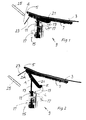
- Figs. 1 and 2 show a part of a front flap 3 with a trailing edge 5 and a lateral reinforcement 7.
- the trailing edge 5 of the front flap 3 is movable by a device 9 from the initial position shown in Fig. 1 in a raised position, in a improved pedestrian protection is achieved (FIG. 2).
- FIG. 2 In the drawing, only one of each arranged on each side of the front door 3 device 9 is shown.
- the device 9 comprises in detail an actuator 11, the piston rod 13 can perform a linear movement upwards. In the extended position of the piston rod 13, this can be locked, which is not shown in detail in the drawing.
- the actuator 11 is of a Bearing part 15 is held, which is formed with holes 17 for its attachment to the body of the vehicle. In addition, the bearing part 15 on a bearing L, in which the first end of a lever 19 is received. The second end of the cranked lever 19 is connected via a hinge E to the first end of a deployment lever 21.
- the second end of the deployment lever 21 is connected to the reinforcement 7 of the front flap 3 via a joint DA.
- a hinge A is provided between the joints E and DA on the release lever 21, to which the free end of the piston rod 13 of the actuator 11 engages.
- the joint DA moves when lifting the trailing edge 5 of the front door 3 from the initial position shown in FIG. 1 along a circular path in the position shown in Fig. 2.
- the fulcrum of the circular path is formed by a lock bracket, which is arranged in the front region of the front flap 3 (not shown in the drawing).
- a flat cover member 23 is attached to the release lever 21 approximately at right angles. In the starting position shown in Fig. 1, the cover member 23 extends into the space below the trailing edge 5 of the front door 3 and an adjoining windshield 25th
- the cover member 23 is rigidly connected to the release lever 21.
- the linear movement of the piston rod 13 of the actuator 11 and the joints associated with these components is achieved that at the beginning of Ausstellterrorism the release lever 21 is first lifted upwards, so that the cover 23 is also guided without contact with the lower edge of the windshield 25 upwards. Only in the further course of motion, a pivoting movement of the deployment lever 21 and associated therewith a pivoting movement of the rigidly connected to the release lever 21 cover member 23 in the position shown in Fig. 2.
Landscapes
- Engineering & Computer Science (AREA)
- Mechanical Engineering (AREA)
- Superstructure Of Vehicle (AREA)
Abstract
Description
- Die Erfindung bezieht sich auf ein Fahrzeug mit einer in Scharnieren aufgenommen Frontklappe, einem im vorderen Frontklappenbereich angeordneten Schloss, einer Vorrichtung zum Anheben der Hinterkante der Frontklappe und einer Einrichtung zum Abdecken des bei angehobener Hinterkante entstehenden Spaltes zwischen der Frontklappe und einer sich daran nach hinten anschließenden Windschutzscheibe.
- Gattungsgemäße Vorrichtungen sind in verschiedenen Ausführungen bekannt. So ist beispielsweise schon vorgeschlagen worden, durch einen Airbag die Fuge abzudecken, die bei einer aktiven Frontklappe entsteht, dass heißt, wenn sich die Hinterkante der Frontklappe in ihrer angehoben Stellung befindet, um einen verbesserten Fußgängerschutz zu erreichen. Es sind auch Einrichtungen bekannt, bei denen eine an der Innenseite der Frontklappe verschiebbar gelagerte Platte herausgefahren wird, wenn die Frontklappe aktiv ist. Die bekannten Einrichtungen zum Abdecken des bei angehobener Hinterkante entstehenden Spaltes zwischen der Frontklappe und der Windschutzscheibe sind insgesamt sehr aufwendig und teilweise nicht reversibel.
- Der vorliegenden Erfindung liegt die Aufgabe zugrunde, eine verbesserte Einrichtung zum Abdecken des bei angehobener Frontklappen-Hinterkante entstehenden Spaltes zu schaffen, die bei größtmöglicher Zuverlässigkeit besonders kostengünstig realisierbar ist.
- Die Aufgabe wird dadurch gelöst, dass die Vorrichtung zum Anheben der Hinterkante der Frontklappe mindestens einen Ausstellhebel umfasst, und dass an dem Ausstellhebel ein von diesem abragendes, flächiges Abdeckteil angeordnet ist, derart, dass es sich bei angehobener Hinterkante in den Raum zwischen der Frontklappe und der Windschutzscheibe hinein erstreckt.
- Die Aufgabe kann auch dadurch gelöst werden, dass im Bereich der Hinterkante der Frontklappe ein von dieser abragendes flächiges Abdeckteil angeordnet ist, derart, dass es sich bei angehobener Hinterkante in den Raum zwischen der Frontklappe und der Windschutzscheibe hineinerstreckt.
- Beide Lösungen haben gemeinsam, dass ein einfach herzustellendes und zu befestigendes Bauteil, nämlich ein flächiges Abdeckteil, fest angeordnet ist. Die Bewegung des Abdeckteiles erfolgt synchron mit der Anstellung der Hinterkante der Frontklappe. Durch die feste Zuordnung bzw. Anbindung an die Frontklappe wird darüber hinaus keine Sensorik und/oder zusätzliche Aktuatorik zur Bewegung des Abdeckteiles benötigt. Ein besonderer Vorteil besteht auch darin, dass die vorgeschlagene Lösung reversibel und nur durch in Augenscheinnahme kontrollierbar ist.
- Die Anordnung des abragenden, flächigen Abdeckteiles an einem Ausstellhebel bzw. unmittelbar an der Frontklappe ist so getroffen, dass das Abdeckteil durch die Bewegung beim Anstellen der Hinterkante der Frontklappe zunächst nach oben durch den stets vorhandenen Spalt zwischen der Frontklappen-Hinterkante und der Windschutzscheibe bewegt wird und dann eine Schwenkbewegung ausübt, wenn die Hinterkante der Frontklappe angestellt wird. In diesem Zusammenhang ist es natürlich besonders vorteilhaft, wenn das Abdeckteil an dem Ausstellhebel festgelegt ist, da dieser meist eine größere Schwenkbewegung vollführt als die Frontklappe.
- Das Abdeckteil kann in der Ausgangslage in dem bei den meisten Fahrzeugen vorhandenen Raum unter dem rückwärtigen Bereich der Frontklappe, dem so genannten Wasserkasten, angeordnet sein. Insofern wird ein ohnehin vorhandener Raum genutzt und kein oder nur ein geringfügiger zusätzlicher Bauraum benötigt.
- Die Unteransprüche 2 bis 4 beinhalten vorteilhafte Ausgestaltungen der Erfindung, wobei insbesondere die Umsetzung mit einer Vorrichtung zum Anheben der Hinterkante der Frontklappe gemäß dem Unteranspruch 4 zweckmäßig ist und sich leicht umsetzen lässt.
- Ein Ausführungsbeispiel der Erfindung ist in der Zeichnung dargestellt und wird nachfolgend näher beschrieben. Es zeigen
- Fig. 1
- eine Vorrichtung zum Anheben der Hinterkante einer Frontklappe und eine damit in Verbindung stehende Einrichtung zum Abdecken des bei angehobener Hinterkante entstehendes Spaltes zwischen der Frontklappe und einer sich daran nach hinten anschließenden Windschutzscheibe und
- Fig. 2
- die Anordnung gemäß Fig. 1 bei aktiver Frontklappe, dass heißt, wenn die Hinterkante der Frontklappe angestellt ist.
- Die Fig. 1 und 2 zeigen einen Teil einer Frontklappe 3 mit einer Hinterkante 5 und einer seitlichen Verstärkung 7. Die Hinterkante 5 der Frontklappe 3 ist durch eine Vorrichtung 9 von der in Fig. 1 dargestellten Ausgangslage in eine angehobene Stellung bewegbar, in der ein verbesserter Fußgängerschutz erreicht wird (Fig. 2). In der Zeichnung ist nur eine von auf jeder Seite der Frontklappe 3 angeordneten Vorrichtung 9 gezeigt.
- Die Vorrichtung 9 umfasst im Einzelnen einen Aktuator 11, dessen Kolbenstange 13 eine Linearbewegung nach oben ausführen kann. In der ausgefahrenen Stellung der Kolbenstange 13 kann diese arretiert werden, was in der Zeichnung jedoch nicht näher dargestellt ist. Der Aktuator 11 wird von einem Lagerteil 15 gehalten, welches mit Bohrungen 17 zu seiner Befestigung an der Karosserie des Fahrzeuges ausgebildet ist. Außerdem weist das Lagerteil 15 ein Festlager L auf, in dem das erste Ende eines Hebels 19 aufgenommen ist. Das zweite Ende des gekröpft ausgebildeten Hebels 19 ist über ein Gelenk E mit dem ersten Ende eines Ausstellhebels 21 verbunden.
- Wie insbesondere Fig. 2 zeigt, steht das zweite Ende des Ausstellhebels 21 über ein Gelenk DA an der Verstärkung 7 der Frontklappe 3 in Verbindung. Schließlich ist zwischen den Gelenken E und DA am Ausstellhebel 21 ein Drehgelenk A vorgesehen, an dem das freie Ende der Kolbenstange 13 des Aktuators 11 angreift.
- Das Gelenk DA bewegt sich beim Anheben der Hinterkante 5 der Frontklappe 3 von der Ausgangslage gemäß Fig. 1 entlang einer Kreisbahn in die in Fig. 2 gezeigte Stellung. Der Drehpunkt der Kreisbahn wird dabei durch einen Schlossbügel gebildet, welcher im vorderen Bereich der Frontklappe 3 angeordnet ist (in der Zeichnung nicht dargestellt).
- Wie in den Fig. 1 und 2 deutlich zu erkennen, ist an dem Ausstellhebel 21 etwa im rechten Winkel ein flächiges Abdeckteil 23 befestigt. In der in Fig. 1 dargestellten Ausgangslage erstreckt sich das Abdeckteil 23 in den Raum unterhalb der Hinterkante 5 der Frontklappe 3 und einer sich daran anschließenden Windschutzscheibe 25.
- Wird die Hinterkante 5 der Frontklappe 3 angehoben, wie dies in Fig. 2 dargestellt ist, dann wird durch das Abdeckteil 23 der Spalt zwischen der Hinterkante 5 der Frontklappe 3 und der Windschutzscheibe 25 größtenteils abgedeckt, so dass sich in dem Spalt keine Gliedmaßen eines auf die Frontklappe 3 aufschlagenden Fußgängers oder Zweiradfahrers verfangen können.
- Das Abdeckteil 23 ist starr mit dem Ausstellhebel 21 verbunden. Durch die Kinematik des Ausstellhebels 21 in Verbindung mit dem Hebel 19, der Linearbewegung der Kolbenstange 13 des Aktuators 11 und den mit diesen Bauteilen in Verbindung stehenden Gelenken wird erreicht, dass zu Beginn Ausstellbewegung der Ausstellhebel 21 zunächst nach oben angehoben wird, so dass das Abdeckteil 23 ohne Kontakt mit dem unteren Rand der Windschutzscheibe 25 ebenfalls nach oben geführt wird. Erst im weiteren Bewegungsablauf erfolgt eine Schwenkbewegung des Ausstellhebels 21 und damit verbunden eine Schwenkbewegung des starr mit dem Ausstellhebel 21 verbundenen Abdeckteiles 23 in die in Fig. 2 gezeigte Position.
Claims (5)
- Fahrzeug mit einer in Scharnieren aufgenommenen Frontklappe, einem im vorderen Frontklappenbereich angeordneten Schloss, einer Vorrichtung zum Anheben der Hinterkante der Frontklappe und einer Einrichtung zum Abdecken des bei angehobener Hinterkante entstehenden Spaltes zwischen der Frontklappe und einer sich daran nach hinten anschließenden Windschutzscheibe, dadurch gekennzeichnet, dass die Vorrichtung (9) zum Anheben der Hinterkante (5) der Frontklappe (3) mindestens einen Ausstellhebel (21) umfasst, und dass an dem Ausstellhebel (21) ein von diesem abragendes, flächiges Abdeckteil (23) angeordnet ist, derart, dass es sich bei angehobener Hinterkante (5) in den Raum zwischen der Frontklappe (3) und der Windschutzscheibe (25) hinein erstreckt.
- Fahrzeug nach Anspruch 1, dadurch gekennzeichnet, dass das Abdeckteil (23) starr an dem Ausstellhebel (21) befestigt ist.
- Fahrzeug nach Anspruch 1 oder 2, dadurch gekennzeichnet, dass das Abdeckteil (21) aus mehreren Platten zusammengesetzt ist und sich annähernd über die gesamte Breite der Frontklappe (3) erstreckt.
- Fahrzeug nach einem der Ansprüche 1 bis 3, dadurch gekennzeichnet, dass die Vorrichtung (9) zum Anheben der Hinterkante (5) der Frontklappe (3)- einen karosseriefest angeordneten Aktuator (11) umfasst der in eine vorgegebene Richtung nach oben ausfahrbar ist,- dass an dem Aktuator (11) ein Festlager L angeordnet ist, welches schwenkbar das erste Ende eines Hebels (19) aufnimmt,- dass an dem zweiten Ende des Hebels (19) schwenkbar das erste Ende des Ausstellhebels (21) angeordnet ist,- dass das zweite Ende des Ausstellhebels (21) schwenkbar mit der Frontklappe (3) verbunden ist und- dass zwischen den Enden des Ausstellhebels (21) über ein Drehgelenk A der Aktuator (11) angreift.
- Fahrzeug mit einer in Scharnieren aufgenommenen Frontklappe, einem im vorderen Frontklappenbereich angeordneten Schloss, einer Vorrichtung zum Anheben der Hinterkante der Frontklappe und einer Einrichtung zum Abdecken des bei angehobener Hinterkante entstehenden Spaltes zwischen der Frontklappe (5) und einer sich daran nach hinten anschließenden Windschutzscheibe, dadurch gekennzeichnet, dass im Bereich der Hinterkante der Frontklappe (3) ein von dieser abragendes, flächiges Abdeckteil (23) angeordnet ist, derart, dass es sich bei angehobener Hinterkante (5) in den Raum zwischen der Frontklappe (3) und der Windschutzscheibe (25) hinein erstreckt.
Applications Claiming Priority (1)
| Application Number | Priority Date | Filing Date | Title |
|---|---|---|---|
| DE200610004017 DE102006004017B4 (de) | 2006-01-27 | 2006-01-27 | Fahrzeug mit einer Frontklappe |
Publications (2)
| Publication Number | Publication Date |
|---|---|
| EP1813483A1 true EP1813483A1 (de) | 2007-08-01 |
| EP1813483B1 EP1813483B1 (de) | 2009-03-11 |
Family
ID=37882190
Family Applications (1)
| Application Number | Title | Priority Date | Filing Date |
|---|---|---|---|
| EP20060025758 Not-in-force EP1813483B1 (de) | 2006-01-27 | 2006-12-13 | Kraftfahrzeug mit anhebbarer Frontklappe |
Country Status (3)
| Country | Link |
|---|---|
| EP (1) | EP1813483B1 (de) |
| DE (2) | DE102006004017B4 (de) |
| ES (1) | ES2321129T3 (de) |
Families Citing this family (2)
| Publication number | Priority date | Publication date | Assignee | Title |
|---|---|---|---|---|
| DE102009040405B4 (de) * | 2009-09-07 | 2022-11-17 | Bayerische Motoren Werke Aktiengesellschaft | Scharnier |
| DE102023129342B4 (de) * | 2023-10-25 | 2025-12-11 | Bayerische Motoren Werke Aktiengesellschaft | Kraftfahrzeug mit einer Fronthaube aufweisend eine Abdeckung |
Citations (5)
| Publication number | Priority date | Publication date | Assignee | Title |
|---|---|---|---|---|
| EP1153810A2 (de) * | 2000-04-29 | 2001-11-14 | Volkswagen Aktiengesellschaft | Sicherheitseinrichtung an einem Fahrzeug, insbesondere an einem Kraftfahrzeug |
| DE10205626A1 (de) * | 2002-02-12 | 2003-08-14 | Suspa Tec Gmbh | Fußgänger-Schutz-Vorrichtung |
| WO2004089702A1 (de) * | 2003-04-11 | 2004-10-21 | Daimlerchrysler Ag | Sicherheitsvorrichtung |
| DE202004014928U1 (de) * | 2004-09-24 | 2004-12-02 | Festo Ag & Co | Kraftfahrzeug mit Sicherheitseinrichtung |
| DE102004027782B3 (de) * | 2004-06-08 | 2005-09-29 | Benteler Automobiltechnik Gmbh | Sicherheitsvorrichtung |
Family Cites Families (2)
| Publication number | Priority date | Publication date | Assignee | Title |
|---|---|---|---|---|
| DE10132950B4 (de) * | 2000-07-19 | 2013-06-27 | Volkswagen Ag | Sicherheitseinrichtung für Fahrzeuge |
| DE10039107A1 (de) * | 2000-08-07 | 2002-02-28 | Acts Adv Car Tech Sys Gmbh | Sicherheitseinrichtung für ein Kraftfahrzeug |
-
2006
- 2006-01-27 DE DE200610004017 patent/DE102006004017B4/de not_active Expired - Lifetime
- 2006-12-13 EP EP20060025758 patent/EP1813483B1/de not_active Not-in-force
- 2006-12-13 DE DE200650003083 patent/DE502006003083D1/de active Active
- 2006-12-13 ES ES06025758T patent/ES2321129T3/es active Active
Patent Citations (5)
| Publication number | Priority date | Publication date | Assignee | Title |
|---|---|---|---|---|
| EP1153810A2 (de) * | 2000-04-29 | 2001-11-14 | Volkswagen Aktiengesellschaft | Sicherheitseinrichtung an einem Fahrzeug, insbesondere an einem Kraftfahrzeug |
| DE10205626A1 (de) * | 2002-02-12 | 2003-08-14 | Suspa Tec Gmbh | Fußgänger-Schutz-Vorrichtung |
| WO2004089702A1 (de) * | 2003-04-11 | 2004-10-21 | Daimlerchrysler Ag | Sicherheitsvorrichtung |
| DE102004027782B3 (de) * | 2004-06-08 | 2005-09-29 | Benteler Automobiltechnik Gmbh | Sicherheitsvorrichtung |
| DE202004014928U1 (de) * | 2004-09-24 | 2004-12-02 | Festo Ag & Co | Kraftfahrzeug mit Sicherheitseinrichtung |
Also Published As
| Publication number | Publication date |
|---|---|
| DE102006004017A1 (de) | 2007-08-09 |
| DE102006004017B4 (de) | 2007-11-29 |
| DE502006003083D1 (de) | 2009-04-23 |
| EP1813483B1 (de) | 2009-03-11 |
| ES2321129T3 (es) | 2009-06-02 |
Similar Documents
| Publication | Publication Date | Title |
|---|---|---|
| EP2523830B1 (de) | Vorrichtung für ein kraftfahrzeug mit einer bewegbar gelagerten kameraeinheit sowie kraftfahrzeug | |
| EP3212470B1 (de) | Kraftfahrzeug, umfassend eine frontklappe, die über zwei scharniergelenke schwenkbar an einer karosserie angeordnet ist | |
| DE10047406A1 (de) | Kopfstütze | |
| EP2862757B1 (de) | Verstellvorrichtung für eine Frontklappe und zugehöriges Kraftfahrzeug | |
| DE10111096A1 (de) | Anordnung einer Frontklappe an einem Fahrzeug | |
| DE102008057880A1 (de) | Vorrichtung zur Verstellung einer Klappe für ein Kraftfahrzeug | |
| DE102013017475A1 (de) | Verstellvorrichtung für eine Frontklappe | |
| DE102013017453A1 (de) | Verstellvorrichtung für eine Frontklappe und zugehöriges Kraftfahrzeug | |
| DE102016106001A1 (de) | Anordnung für ein Fahrzeugdach, Fahrzeugdach und Verfahren | |
| AT511710B1 (de) | Vorrichtung zum anstellen einer motorhaube | |
| DE102015010395B3 (de) | Frontklappenscharnier und zugehöriges Kraftfahrzeug | |
| EP1920962A2 (de) | Verdeck für ein Kraftfahrzeug, insbesondere Cabriolet-Fahrzeug, mit einem faltbaren Dach | |
| AT13077U1 (de) | Vorrichtung zum Anstellen einer Motorhaube | |
| DE102009040409A1 (de) | Scharnier und Verfahren zum Betreiben eines Scharniers | |
| DE102017121577B4 (de) | Verdeckkastendeckelanordnung mit Stelllenkern und Antriebslenkeranordnung | |
| DE102011103527A1 (de) | Schiebedachsystem | |
| EP1813483B1 (de) | Kraftfahrzeug mit anhebbarer Frontklappe | |
| DE102010023283A1 (de) | Kraftfahrzeugkarosserie mit reversierbarer Haube | |
| EP1970508A2 (de) | Vorrichtung zur Arretierung eines schwenkbaren Bauteiles eines Kraftfahrzeuges | |
| DE102014114804B4 (de) | Cabriolet-Verdeck mit Verschlusssystem | |
| EP1813484B1 (de) | Fahrzeug mit einer in Scharnieren aufgenommen Frontklappe | |
| DE102005059274B4 (de) | Verblendungsvorrichtung für Fahrzeugdachsysteme mit öffnungsfähigem Deckel | |
| DE102004035638B4 (de) | Verfahren zum Schließen einer Heckklappe eines Kraftfahrzeugs | |
| DE102005023224B4 (de) | Betätigungsvorrichtung für Fanghaken einer Fronthaube | |
| DE102013003137A1 (de) | Klappe für ein Kraftfahrzeug und zugehöriges Kraftfahrzeug |
Legal Events
| Date | Code | Title | Description |
|---|---|---|---|
| PUAI | Public reference made under article 153(3) epc to a published international application that has entered the european phase |
Free format text: ORIGINAL CODE: 0009012 |
|
| AK | Designated contracting states |
Kind code of ref document: A1 Designated state(s): AT BE BG CH CY CZ DE DK EE ES FI FR GB GR HU IE IS IT LI LT LU LV MC NL PL PT RO SE SI SK TR |
|
| AX | Request for extension of the european patent |
Extension state: AL BA HR MK YU |
|
| 17P | Request for examination filed |
Effective date: 20080201 |
|
| AKX | Designation fees paid |
Designated state(s): DE ES FR IT |
|
| GRAC | Information related to communication of intention to grant a patent modified |
Free format text: ORIGINAL CODE: EPIDOSCIGR1 |
|
| GRAP | Despatch of communication of intention to grant a patent |
Free format text: ORIGINAL CODE: EPIDOSNIGR1 |
|
| GRAC | Information related to communication of intention to grant a patent modified |
Free format text: ORIGINAL CODE: EPIDOSCIGR1 |
|
| GRAP | Despatch of communication of intention to grant a patent |
Free format text: ORIGINAL CODE: EPIDOSNIGR1 |
|
| GRAS | Grant fee paid |
Free format text: ORIGINAL CODE: EPIDOSNIGR3 |
|
| GRAA | (expected) grant |
Free format text: ORIGINAL CODE: 0009210 |
|
| AK | Designated contracting states |
Kind code of ref document: B1 Designated state(s): DE ES FR IT |
|
| REF | Corresponds to: |
Ref document number: 502006003083 Country of ref document: DE Date of ref document: 20090423 Kind code of ref document: P |
|
| REG | Reference to a national code |
Ref country code: ES Ref legal event code: FG2A Ref document number: 2321129 Country of ref document: ES Kind code of ref document: T3 |
|
| PLBE | No opposition filed within time limit |
Free format text: ORIGINAL CODE: 0009261 |
|
| STAA | Information on the status of an ep patent application or granted ep patent |
Free format text: STATUS: NO OPPOSITION FILED WITHIN TIME LIMIT |
|
| 26N | No opposition filed |
Effective date: 20091214 |
|
| PGFP | Annual fee paid to national office [announced via postgrant information from national office to epo] |
Ref country code: ES Payment date: 20131219 Year of fee payment: 8 Ref country code: IT Payment date: 20131220 Year of fee payment: 8 |
|
| PGFP | Annual fee paid to national office [announced via postgrant information from national office to epo] |
Ref country code: FR Payment date: 20131220 Year of fee payment: 8 |
|
| REG | Reference to a national code |
Ref country code: DE Ref legal event code: R084 Ref document number: 502006003083 Country of ref document: DE |
|
| REG | Reference to a national code |
Ref country code: DE Ref legal event code: R084 Ref document number: 502006003083 Country of ref document: DE Effective date: 20141212 |
|
| REG | Reference to a national code |
Ref country code: FR Ref legal event code: ST Effective date: 20150831 |
|
| PG25 | Lapsed in a contracting state [announced via postgrant information from national office to epo] |
Ref country code: FR Free format text: LAPSE BECAUSE OF NON-PAYMENT OF DUE FEES Effective date: 20141231 |
|
| PG25 | Lapsed in a contracting state [announced via postgrant information from national office to epo] |
Ref country code: IT Free format text: LAPSE BECAUSE OF NON-PAYMENT OF DUE FEES Effective date: 20141213 |
|
| REG | Reference to a national code |
Ref country code: ES Ref legal event code: FD2A Effective date: 20160126 |
|
| PG25 | Lapsed in a contracting state [announced via postgrant information from national office to epo] |
Ref country code: ES Free format text: LAPSE BECAUSE OF NON-PAYMENT OF DUE FEES Effective date: 20141214 |
|
| PGFP | Annual fee paid to national office [announced via postgrant information from national office to epo] |
Ref country code: DE Payment date: 20151231 Year of fee payment: 10 |
|
| REG | Reference to a national code |
Ref country code: DE Ref legal event code: R231 Ref document number: 502006003083 Country of ref document: DE |
|
| PG25 | Lapsed in a contracting state [announced via postgrant information from national office to epo] |
Ref country code: DE Free format text: LAPSE BECAUSE OF THE APPLICANT RENOUNCES Effective date: 20161007 |