EP1812295B1 - Appareillage et procede de remplissage de récipients - Google Patents
Appareillage et procede de remplissage de récipients Download PDFInfo
- Publication number
- EP1812295B1 EP1812295B1 EP05811420A EP05811420A EP1812295B1 EP 1812295 B1 EP1812295 B1 EP 1812295B1 EP 05811420 A EP05811420 A EP 05811420A EP 05811420 A EP05811420 A EP 05811420A EP 1812295 B1 EP1812295 B1 EP 1812295B1
- Authority
- EP
- European Patent Office
- Prior art keywords
- enclosure
- nozzle
- sterile
- opening
- sterile fluid
- Prior art date
- Legal status (The legal status is an assumption and is not a legal conclusion. Google has not performed a legal analysis and makes no representation as to the accuracy of the status listed.)
- Active
Links
- 238000011049 filling Methods 0.000 title claims abstract description 27
- 238000000034 method Methods 0.000 title claims description 17
- 239000012530 fluid Substances 0.000 claims abstract description 82
- 238000004140 cleaning Methods 0.000 claims abstract description 57
- 239000000945 filler Substances 0.000 claims abstract description 33
- 238000007789 sealing Methods 0.000 claims abstract description 7
- 230000009969 flowable effect Effects 0.000 claims description 9
- 238000003754 machining Methods 0.000 claims description 2
- 238000011010 flushing procedure Methods 0.000 abstract description 3
- 239000000047 product Substances 0.000 description 16
- 230000001954 sterilising effect Effects 0.000 description 9
- 230000000844 anti-bacterial effect Effects 0.000 description 8
- 239000003899 bactericide agent Substances 0.000 description 8
- 238000004659 sterilization and disinfection Methods 0.000 description 7
- 239000012263 liquid product Substances 0.000 description 5
- 239000000443 aerosol Substances 0.000 description 4
- 239000007788 liquid Substances 0.000 description 4
- 239000011087 paperboard Substances 0.000 description 4
- 230000000903 blocking effect Effects 0.000 description 3
- 239000010419 fine particle Substances 0.000 description 3
- XLYOFNOQVPJJNP-UHFFFAOYSA-N water Substances O XLYOFNOQVPJJNP-UHFFFAOYSA-N 0.000 description 3
- 238000011109 contamination Methods 0.000 description 2
- 229920001971 elastomer Polymers 0.000 description 2
- 239000004033 plastic Substances 0.000 description 2
- 229920003023 plastic Polymers 0.000 description 2
- 239000007921 spray Substances 0.000 description 2
- 239000003206 sterilizing agent Substances 0.000 description 2
- 238000012371 Aseptic Filling Methods 0.000 description 1
- 241001481828 Glyptocephalus cynoglossus Species 0.000 description 1
- 239000011111 cardboard Substances 0.000 description 1
- 239000000969 carrier Substances 0.000 description 1
- 238000004891 communication Methods 0.000 description 1
- 239000000356 contaminant Substances 0.000 description 1
- 229910003460 diamond Inorganic materials 0.000 description 1
- 239000010432 diamond Substances 0.000 description 1
- 238000007599 discharging Methods 0.000 description 1
- 238000005429 filling process Methods 0.000 description 1
- 239000007789 gas Substances 0.000 description 1
- 238000012544 monitoring process Methods 0.000 description 1
- 238000009740 moulding (composite fabrication) Methods 0.000 description 1
- 239000006199 nebulizer Substances 0.000 description 1
- 238000004806 packaging method and process Methods 0.000 description 1
- 230000002093 peripheral effect Effects 0.000 description 1
- 229920006395 saturated elastomer Polymers 0.000 description 1
- 238000005507 spraying Methods 0.000 description 1
- 239000008223 sterile water Substances 0.000 description 1
Images


Classifications
-
- B—PERFORMING OPERATIONS; TRANSPORTING
- B65—CONVEYING; PACKING; STORING; HANDLING THIN OR FILAMENTARY MATERIAL
- B65B—MACHINES, APPARATUS OR DEVICES FOR, OR METHODS OF, PACKAGING ARTICLES OR MATERIALS; UNPACKING
- B65B55/00—Preserving, protecting or purifying packages or package contents in association with packaging
- B65B55/02—Sterilising, e.g. of complete packages
- B65B55/027—Packaging in aseptic chambers
Definitions
- This invention relates generally to a method and apparatus for filling serially-presented containers with flowable product.
- the Elopak® P-S120UC machine is a double-indexed carton forming, filling, and sealing machine that includes a box-shaped enclosure surrounding a pair of carton filler nozzles.
- a carton opening is formed in the bottom of the enclosure and is shaped to receive a pair of open-ended cartons into positions axially aligned with and encompassing respective lower portions of the carton filler nozzles.
- a lift mechanism lifts cartons into these positions within the enclosure from a conveyor that runs beneath the enclosure, and then lowers the cartons as the cartons are filled.
- the P-S120UC machine includes a clean-in-place (CIP) circuit that is arranged to introduce cleaning fluid into the carton filler nozzles and to drain the cleaning fluid from the nozzles as the nozzles are being cleaned in place.
- CIP clean-in-place
- a removable cleaning manifold obturates the mouths of the nozzles and connects the nozzles to CIP drain piping.
- the cleaning manifold directs cleaning solution as interior surfaces of the nozzles are being cleaned, in particular sterilized. To install and remove the manifold an operator must reach into the enclosure.
- the P-S120UC machine also includes piping for injecting air passed through a high efficiency particulate air filter (known as HEPA air) into the enclosure to maintain a sterile positive-pressure environment around the nozzles during product dispensing operations.
- HEPA air high efficiency particulate air filter
- the HEPA piping defines a sterile fluid circuit that is separate from the CIP circuit.
- US-A-3,486,295 discloses a method and device according to the preambles of claims 15 and 1, respectively, for filling a plastics-coated paper or cardboard container under sterilized conditions, the device comprising a chamber into which an unsterilized open-topped container is lifted by a vertically displaceable bottom plate.
- the plate sealingly closes the chamber from below, a sterilizing agent is admitted into the chamber via an outlet pipe to sterilize both the chamber and the interior of the container, the sterilizing agent (which may be any of a number of heat carriers, for example steam, at sterilizing temperature, or chemically sterilizing gases or vapours) leaving the chamber via an outlet pipe, the filling liquid is then introduced into the container via a filling nozzle, having its lower end in the chamber, after which the container top is pressed closed, and the filled and closed container is then removed subsequent to re-opening of the chamber.
- the sterilizing agent which may be any of a number of heat carriers, for example steam, at sterilizing temperature, or chemically sterilizing gases or vapours
- the method and the device of EP-A-303135 are intended for the aseptic filling of containers, for example bottles, with liquid on a vertical turret machine.
- a hot sterilization medium of gaseous vapour in particular hot saturated water vapour, is applied to the inner surfaces of the container, to its mouth and to its outer surface adjoining the mouth of each container.
- the container is arranged in a bell-form chamber which at least partially accommodates the container.
- the sterilization medium is introduced into the container at a distance from the mouth by means of a filling tube which is used for subsequent filling, so that, at least during part of the sterilization phase, a stream of sterilization medium from the filling tube comes into contact with the inner surface of the container bottom and is moved radially outwards along the bottom, upwards along the inner surface of the peripheral container wall and outwards around the mouth of the container and also downwards.
- water vapour is fed anew downwardly through the filling tube, whereby the filling tube is sterilised and cleaned at least internally.
- a cleaning medium e.g. sterile water
- WO79/01074 discloses a method and apparatus for applying a bactericide aerosol to a container for sterilization of the same.
- a reservoir feeds a liquid bactericide into a nebulizing chamber in which is operatively mounted a transducer that is energized by high frequency electrical power for producing vibrational energy for directly energizing the bactericide to nebulize the liquid bactericide into fine particles.
- a source of pressurized ain is connected to the nebulizer to provide a carrier air for conveying the fine particles of bactericide through a transfer tube to a heated nozzle for spraying the fine particles into a container.
- a monitor is operatively connected in the flow path of the bactericide aerosol for monitoring the flow rate of the bactericide aerosol.
- US-A-6,018,931 discloses a method and a support for supporting a package in a steam sterilizer, featuring support members configured and positioned to support only at least a portion of at least two opposed side edges, but not a side face, of the package.
- a diamond shape is particularly preferred for each support member as, when rotated at an angle, its facets provide line contact with appropriate side edges of the package.
- apparatus for filling serially-presented containers with flowable product comprising:
- the apparatus preferably includes a cleaning cover removably attachable across the opening so as to close the opening when the cleaning fluid is to be caused to flow through the enclosure and the nozzle, whilst the method includes sealing the enclosure from the ambient atmosphere before flushing the interior of the enclosure with the cleaning fluid. It is thereby possible more effectively to prevent contamination of the product being dispensed.
- the apparatus also preferably includes container guides disposed in and integral with the enclosure and serving to guide the motion of a container into the enclosure to around the nozzle for filling. It is thereby possible to simplify the provision of the carton guides inside the enclosure and to improve the accuracy of those guides.
- the apparatus which fills serially-presented paperboard cartons with liquid product while maintaining a sterile, contaminant-free environment in a zone immediately surrounding a carton filler nozzle of the apparatus, comprises the carton filler nozzle, which is connectible to a source of liquid product, an enclosure at least partially surrounding the carton filler nozzle, a carton opening formed in the bottom of the enclosure and shaped to receive an open-ended carton into a position axially aligned with and encompassing a portion of the carton filler nozzle, and a sterile fluid inlet port of the enclosure.
- the sterile fluid inlet port is connected to a source of sterile fluid and is arranged to admit sterile fluid from the source of sterile fluid into the enclosure such that the interior of the enclosure, the exterior of the filler nozzle, and any carton or liquid product present in the enclosure are flushed by sterile fluid and a generally sterile, positive-pressure fluid environment is maintained around the nozzle.
- the sterile fluid inlet port and the carton filler nozzle are connectible into a cleaning solution circuit such that the sterile fluid inlet port acts as a cleaning solution outlet port for cleaning solution entering the enclosure through the nozzle.
- the enclosure may have carton guides formed into its interior surface and arranged to guide the motion of a carton into the enclosure to around the filler nozzle for filling.
- the cleaning fluid circuit may be an open circuit or a closed circuit, as may be the sterile fluid circuit.
- the present example is of an apparatus 20 , with a angle enclosure 26.
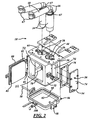
- the apparatus 20 for filling serially-presented paperboard cartons 22 with liquid product 23 from sources 70 (in the form of a pair of filler pumps) of liquid product while maintaining a sterile, contaminant-free environment in a region immediately surrounding a pair of carton filler nozzles 24 of the apparatus 20 is shown in Figures 1 to 11 .
- the apparatus 20 includes a generally rectilinear, box-shaped enclosure 26 shaped to surround at least partially the carton filler nozzles 24. As best shown in Figures 2 and 3 , two generally circular nozzle openings 28 are formed in an upper wall 30 of the enclosure 26 and are shaped to receive the nozzles 24.
- the apparatus 20 also includes a carton opening, best shown at 32 in Figures 9 and 10 , that is formed in the bottom 34 of the enclosure 26 and is shaped to receive a pair of open-topped, plastics-coated paperboard cartons 22 into general axial alignment with the nozzles 24 as shown in Figures 7, 8 , and 10 .
- the apparatus 20 also includes a source 36 of clean, sterile fluid 37, such as HEPA air, and a pair of sterile fluid inlet ports 38 of the enclosure 26.
- the ports 38 are best shown in Figures 5 , 9, and 10 to 12 . As shown schematically in Figure 12 , the ports 38 are in fluid communication with the source 36 of clean, sterile air and admit the air from the source 36 into the enclosure 26.
- the inlet ports 38 direct the air at the respective nozzles 24 such that the exterior surfaces of the nozzles 24, the interior of the enclosure 26, and the exposed surfaces of any carton 22 or product 23 present in the enclosure 26 are flushed by the air to maintain a more sterile, contaminant-free environment in a region immediately surrounding the nozzles 24.
- continuously flushing the enclosure 26 with clean, sterile air creates and maintains a generally sterile, positive-pressure fluid environment around the nozzles 24.
- Each of the pair of inlet ports 38 is circular in shape and is provided in a back wall 40 of the enclosure 26 as shown in Figures 9 to 11 .
- a pair of air lines 42 is connected to the inlet ports 38 so that clean sterile air can be pumped into the enclosure 26 through the ports 38. This creates an overpressure environment within the enclosure 26 and around the nozzles 24 to keep the nozzles clean and sterile as they fill the cartons 22 witch the product 23.
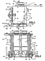
- eight vertically-oriented carton guides 44 form corners within the enclosure 26 and are shaped and positioned, by machining of the interior surface of the enclosure 26, to guide the motion of two open-topped cartons 22 at a time when a carton lifter 46 simultaneously lifts the cartons from a conveyor 48 through the carton opening 32 into respective initial fill positions, and thereafter lowers the cartons.
- the open tops of the cartons 22 surround the respective nozzles 24. Once the nozzles 24 begin filling the cartons 22 with the product 23, the carton lifter 46 begins lowering the cartons 22 back down to the conveyor 48.
- the carton lifter 46 lowers the cartons 22 at a rate that maintains the surface level of the product 23 in the cartons 22 at an approximately constant level relative to the enclosure 26, as shown in Figures 8 and 10 .
- the eight carton guides 44 are vertically-oriented structures of the enclosure 26 and slidably receive respective top corners and vertical edges of a pair of cartons 22 carried by the carton lifter 46 as the lifter cycles up and down.
- a generally rectangular cleaning cover shown at 56 in Figures 1 to 6 and 11 , is removably attachable across the opening 32 to allow a cleaning solution 57 to be prevented from falling from the enclosure 26 when the nozzles 24 and the interior of the enclosure 26 are periodically cleaned as shown in Figure 11 .
- the cover 56 has exterior latches 58 that allow an operator to lock the cover 56 into position across the opening 32 without contaminating the nozzles 24 or the enclosure interior by touching the nozzles 24 or the guides 44. This allows the nozzles 24 and the enclosure interior to be cleaned in place and sterilized without danger of recontamination. In other words, the insides and outsides of the nozzles 24 and the guides 44 and their environment can be cleaned, particularly sterilized, without any human contact with those structures.
- a rubber seal 60 is supported in a seal receptacle 62 formed along and adjacent to a periphery of the cover 56 and is positioned to engage a seal contact surface 64 surrounding the opening 32 to seal-in the cleaning solution 57 and the pressure used to clean the nozzles 24 and the interior of the enclosure 26.
- the seal 60 is of substantially rectangular cross-section, maybe rounded at its cross-sectional corners, and is supported in the seal receptacle 62 of the cover 56 so that, when the cover 56 is removed, the seal 60 stays with the cover 56.
- the seal contact surface 64 is disposed on an " outside lower edge zone of the enclosure 26 surrounding the opening 32, rather than on an interior surface of the carton opening 32, to ensure that all of the inside surface of the enclosure 26 can be swept by the cleaning solution 57.
- Annular flanges 66 are provided around the nozzles 24 and form seals between the nozzles 24 and the upper wall 30 of the enclosure 26 where the nozzles 24 enter the upper wall 30 through the pair of circular openings 28.
- filler elbows 67 and arms 68 are provided; they connect the pair of nozzles 24 to the respective filler pumps 70.
- the opposing side walls 52 of the enclosure 26 have respective, generally rectangular, side access openings 72 covered by respective, generally rectangular, gasketed, removable, side access panels 74.
- the positions of the gaskets 76 for the side access panels 74 are best shown in Figures 2 and 6 to 8 .
- the front wall 50 of the enclosure 26 has a generally rectangular front access opening 78 coverable by a generally rectangular, front access panel (in this case a hinged door) 80 that is supported on hinges 81 and can be opened as shown in Figure 2 to allow access to the filler nozzles 24 so that worn parts, such as rubber nozzle ends, screens, or springs can be removed and replaced.
- the front access door 80 carries a door seal ring 82 that seals between the door 80 and the front access opening 78 when the door 80 is closed.
- a sterile, contaminant-free environment can be maintained in a region immediately surrounding the carton filler nozzles 24 during filling operations by providing and maintaining a generally clean, sterile, positive-pressure fluid environment within the enclosure 26 and around the nozzles 24. This is done by moving HEPA air into the enclosure 26 from the source 36 of HEPA air through the ports 38, as shown in Figure 10 . More specifically, and referring to Figure 12 , HEPA air is routed from its source 36 through a check valve 83, a HEPA blocking valve 84, and then a HEPA valve 86. A CIP return valve 88 is closed and a CIP drain valve 90 is closed. The HEPA air then travels through a tee 92 and into the enclosure 26 through the ports 38.
- the apparatus may include two (as shown in Figure 12 ) or more enclosures 26 rather than just a single enclosure.
- the filler nozzles 24 and the enclosure interior can be periodically cleaned by first removing any cartons 22 present in the enclosure 26. Any cartons 22 present in the enclosure 26 are removed by actuating the carton lifter 46 to lower the cartons 22 back down to the conveyor 48. The cover 56 is then removably and sealingly attached across the opening. 32. If the side access panels 74 have been removed for any reason they are removably and sealingly re-attached across the side access openings 72. If the front access door 80 has been removed or opened, it also is removably and sealingly secured across the front access opening 78. Once the enclosure 26 has been sealed, it is flushed with a cleaning solution 57 as shown in Figure 11 .
- cleaning solution 57 is introduced into a filler tank 25, via input lines 25a and/or via spray nozzles 25b, and thence by way of the pair of filler pumps 70 and the nozzles 24 into the enclosure 26 from a source 59 of cleaning fluid, is allowed to circulate round the interior of the enclosure 26, and is forced or drawn out of the enclosure 26 through the ports 38 and the piping 96 that, in normal operation, carry HEPA air to the enclosure 26.
- the HEPA valve 86 and the CIP return valve 88 are cycled open, allowing fluid to flow through them and exit through the CIP drain valve 90. This cleans and sterilizes the HEPA circuit.
- the HEPA blocking valve 84 is pulsed open. This allows a valve seat of the HEPA blocking valve 84 to be cleaned. Residual cleaning solution 57 is drained from the enclosure 26 by opening a drain valve 100 carried by the cover 56. Fluid remaining in the cover 56 can then flow out through the valve 100 and an attached drain tube.
- the carton filling process can be conducted in a clean, sterile, environment, protecting the product 23 from contaminants, the enclosure 26 and the nozzles 24 can be cleaned without requiring an operator to reach into the enclosure 26, and the sterile fluid inlet port 38 can be used to circulate cleaning solution 57 as part of the CIP circuit rather than incorporating a separate port in the CIP circuit for discharging cleaning solution 57 from the enclosure 26.
Landscapes
- Engineering & Computer Science (AREA)
- Mechanical Engineering (AREA)
- Basic Packing Technique (AREA)
- Filling Of Jars Or Cans And Processes For Cleaning And Sealing Jars (AREA)
- Filling Or Discharging Of Gas Storage Vessels (AREA)
Claims (23)
- Appareil pour remplir des récipients (22) présentés en série avec un produit liquide (23), comprenant :une buse de remplissage (24) pour le raccordement à une source (70) dudit produit (23) ;une enceinte (26) entourant partiellement la buse (24), excepté pour au moins une ouverture (32) afin de recevoir un récipient à extrémité ouverte (22) dans une position axialement alignée avec la buse (24) ;un circuit de fluide stérile ; etun orifice de fluide stérile (38) formé dans une paroi de l'enceinte (26) et faisant partie dudit circuit de fluide stérile, de sorte qu'à l'intérieur de l'enceinte (26), ces parties de surface de la buse (24) exposées dans l'enceinte (26) et ces parties de surface de l'un quelconque des récipients (22) et l'un quelconque des produits liquides (23) exposés dans l'enceinte (26) sont rincées par le fluide stérile (37), afin qu'un environnement de pression positive généralement stérile peut être maintenu autour de la buse (24) ;caractérisé en ce que ledit appareil comprend en outre un circuit de fluide de nettoyage dans lequel l'orifice de fluide stérile (38) et la buse (24) peuvent se raccorder de sorte que l'orifice de fluide stérile (38) sert d'orifice de fluide de nettoyage (38) pour que le fluide de nettoyage (57) s'écoule à travers l'enceinte (26) et la buse (24).
- Appareil selon la revendication 1, dans lequel ledit orifice de fluide stérile (38) est un orifice d'entrée de fluide stérile (38) pour le raccordement à une source (36) de fluide stérile (37) et l'admission du fluide stérile (37) dans l'enceinte (26).
- Appareil selon la revendication 1 ou 2, dans lequel ledit orifice de fluide stérile (38) peut être raccordé dans ledit circuit de fluide de nettoyage de sorte que ledit orifice de fluide stérile (38) sert d'orifice de sortie de fluide de nettoyage (38) pour le fluide de nettoyage (57), qui entre dans l'enceinte (26) par la buse (24).
- Appareil selon l'une quelconque des revendications précédentes, dans lequel le fluide stérile (37) laisse passer l'air par un filtre à air à particules à haute efficacité.
- Appareil selon l'une quelconque des revendications précédentes et comprenant en outre un couvercle de nettoyage (56) pouvant être fixé de manière amovible sur ladite ouverture (32) afin de fermer l'ouverture (32) lorsque ledit fluide de nettoyage (57) est amené à s'écouler à travers l'enceinte (26) et la buse (24).
- Appareil selon la revendication 5, dans lequel le couvercle de nettoyage (56) est tel qu'il permet à un opérateur de bloquer le couvercle (56) en position sur l'ouverture (32) sans toucher la buse (24) ni la surface intérieure de l'enceinte (26).
- Appareil selon la revendication 5 ou 6, et comprenant en outre un joint d'étanchéité élastique annulaire (60) qui est supporté dans un réceptacle annulaire (62) formé le long de et adjacent à une périphérie du couvercle (56) et qui est positionné pour mettre en prise une surface de contact (64) de ladite enceinte (26) entourant l'ouverture (32).
- Appareil selon la revendication 7, dans lequel la surface de contact (64) est disposée sur une zone de bord inférieur externe de l'enceinte (26) entourant l'ouverture (32).
- Appareil selon la revendication 7 ou 8, dans lequel ledit joint d'étanchéité (60) a une section transversale sensiblement rectangulaire.
- Appareil selon l'une quelconque des revendications 5 à 9, et comprenant en outre une soupape d'évacuation (100) supportée par le couvercle (56).
- Appareil selon l'une quelconque des revendications précédentes, dans lequel l'enceinte (26) a une ouverture d'accès frontale (78) pouvant être couverte par un panneau d'accès frontal (80).
- Appareil selon l'une quelconque des revendications précédentes, dans lequel l'enceinte (26) a au moins une ouverture d'accès latérale (72), dont chacune peut être recouverte par un panneau d'accès latéral (74).
- Appareil selon l'une quelconque des revendications précédentes, et comprenant en outre des guides de récipient (44) disposés dans et solidaires de l'enceinte (26) et servant à guider le mouvement d'un récipient (22) dans l'enceinte autour de la buse (24) pour le remplissage.
- Appareil selon la revendication 13, dans lequel les guides (44) ont été formés en usinant ladite enceinte (26).
- Procédé comprenant les étapes consistant à :prévoir une enceinte (26) entourant partiellement une buse de remplissage (24) excepté pour une ouverture (32), amenant des récipients à extrémité ouverte (22) à être reçus en série par ladite ouverture (32) et présentés ainsi, alignés en série et de manière axiale par rapport à ladite buse (24) ;amener ladite buse (24) à distribuer le produit liquide (23) auxdits récipients (23) tour à tour ;amener un fluide stérile (37) s'écoulant à travers un circuit de fluide stérile comprenant un orifice de fluide stérile (38) formé dans une paroi de l'enceinte (26) à rincer ces parties de surface de la buse (24) exposées dans l'enceinte (26) et ces parties de surface du récipient (22) tour à tour et l'un quelconque des produits liquides (23) à l'intérieur de ces dernières, exposées dans l'enceinte (26), afin de maintenir un environnement de pression positive généralement stérile autour de la buse (24) ; etretirer par ladite ouverture (32) l'un quelconque des récipients (22) présents dans l'enceinte (26) ;caractérisé par l'étape consistant à raccorder ledit orifice de fluide stérile (38) et ladite buse (24) dans un circuit de fluide de nettoyage, et amener le fluide de nettoyage (57) à s'écouler à travers ladite buse (24), ladite enceinte (26) et ledit orifice de fluide stérile (38) en série.
- Procédé selon la revendication 15, et comprenant en outre, entre ladite étape consistant à retirer et à amener ledit fluide de nettoyage (57) à s'écouler, l'étape consistant à rendre l'enceinte (26) étanche à l'atmosphère ambiante.
- Procédé selon la revendication 16, dans lequel ladite étape d'étanchéité comprend l'étape consistant à fixer de manière amovible un couvercle de nettoyage (56) sur l'ouverture (32).
- Procédé selon la revendication 17, et comprenant en outre, après ladite étape consistant à amener ledit fluide de nettoyage (57) à s'écouler, l'étape consistant à évacuer un tel fluide de nettoyage (57) par le couvercle (56) en ouvrant une soupape d'évacuation (100) supportée par le couvercle (56).
- Procédé selon l'une quelconque des revendications 16 à 19, dans lequel ladite étape d'étanchéité comprend l'étape consistant à fixer de manière amovible un panneau d'accès latéral (74) sur une ouverture d'accès latérale (72) de l'enceinte (26).
- Procédé selon l'une quelconque des revendications 16 à 19, dans lequel ladite étape d'étanchéité comprend l'étape consistant à fermer une ouverture d'accès frontale (78) de l'enceinte (26).
- Procédé selon l'une quelconque des revendications 15 à 20, dans lequel ladite étape consistant à amener ledit fluide de nettoyage (57) à s'écouler, comprend l'étape consistant à introduire ledit fluide de nettoyage (57) dans l'enceinte (26) par la buse de remplissage (24), le fluide de nettoyage sortant de l'enceinte (26) par ledit orifice de fluide stérile (38).
- Procédé selon l'une quelconque des revendications 15 à 20, dans lequel ladite étape consistant à amener ledit fluide de nettoyage (57) à s'écouler comprend l'étape consistant à introduire ledit fluide de nettoyage (57) dans ladite enceinte (26) par ledit orifice de fluide stérile (38).
- Procédé selon l'une quelconque des revendications 15 à 22, dans lequel ledit fluide stérile (37) est de l'air HEPA.
Priority Applications (1)
| Application Number | Priority Date | Filing Date | Title |
|---|---|---|---|
| EP10186244.9A EP2281751B1 (fr) | 2004-11-16 | 2005-11-16 | Dispositif et procédé pour le remplissage stérile de récipients |
Applications Claiming Priority (3)
| Application Number | Priority Date | Filing Date | Title |
|---|---|---|---|
| US62831804P | 2004-11-16 | 2004-11-16 | |
| US70693305P | 2005-08-10 | 2005-08-10 | |
| PCT/GB2005/004402 WO2006054065A1 (fr) | 2004-11-16 | 2005-11-16 | Appareillage et procede |
Related Child Applications (1)
| Application Number | Title | Priority Date | Filing Date |
|---|---|---|---|
| EP10186244.9 Division-Into | 2010-10-01 |
Publications (2)
| Publication Number | Publication Date |
|---|---|
| EP1812295A1 EP1812295A1 (fr) | 2007-08-01 |
| EP1812295B1 true EP1812295B1 (fr) | 2011-01-05 |
Family
ID=35708934
Family Applications (2)
| Application Number | Title | Priority Date | Filing Date |
|---|---|---|---|
| EP10186244.9A Revoked EP2281751B1 (fr) | 2004-11-16 | 2005-11-16 | Dispositif et procédé pour le remplissage stérile de récipients |
| EP05811420A Active EP1812295B1 (fr) | 2004-11-16 | 2005-11-16 | Appareillage et procede de remplissage de récipients |
Family Applications Before (1)
| Application Number | Title | Priority Date | Filing Date |
|---|---|---|---|
| EP10186244.9A Revoked EP2281751B1 (fr) | 2004-11-16 | 2005-11-16 | Dispositif et procédé pour le remplissage stérile de récipients |
Country Status (5)
| Country | Link |
|---|---|
| US (1) | US20090032137A1 (fr) |
| EP (2) | EP2281751B1 (fr) |
| AT (1) | ATE494226T1 (fr) |
| DE (1) | DE602005025793D1 (fr) |
| WO (1) | WO2006054065A1 (fr) |
Family Cites Families (19)
| Publication number | Priority date | Publication date | Assignee | Title |
|---|---|---|---|---|
| SE313147B (fr) * | 1966-03-07 | 1969-08-04 | Tepar Ag | |
| WO1979001074A1 (fr) | 1978-05-16 | 1979-12-13 | Ex Cell O Corp | Procede et moyens d'application d'un bactericide dans un recipient pour sa sterilisation |
| US4235265A (en) * | 1979-03-05 | 1980-11-25 | The Mead Corporation | Aseptic container filler apparatus |
| DE3809855A1 (de) * | 1987-08-01 | 1989-02-09 | Seitz Enzinger Noll Masch | Verfahren zum aseptischen bzw. sterilen abfuellen von fluessigem fuellgut in behaelter sowie vorrichtung zum durchfuehren dieses verfahrens |
| JPH01167027A (ja) * | 1987-12-18 | 1989-06-30 | Awa Eng Kk | 無菌充填装置 |
| DE3809852A1 (de) * | 1988-03-24 | 1989-10-05 | Seitz Enzinger Noll Masch | Verfahren zum aseptischen bzw. sterilen abfuellen von fluessigem fuellgut in behaelter sowie vorrichtung zum durchfuehren dieses verfahrens |
| GB8826827D0 (en) * | 1988-11-16 | 1988-12-21 | Envair Uk Ltd | Clean air cabinets |
| DE4109731A1 (de) * | 1990-04-28 | 1991-10-31 | Seitz Enzinger Noll Masch | Vorrichtung zum fuellen von behaeltern, insbesondere flaschen mit einem fluessigen fuellgut |
| DE4022142A1 (de) * | 1990-07-11 | 1992-01-16 | Seitz Enzinger Noll Masch | Einrichtung zur ueberwachung der fuellelemente von fuellmaschinen |
| US5265298A (en) * | 1992-02-25 | 1993-11-30 | Raymond Young | Container cleaning system using ionized air flow |
| US5368828A (en) * | 1992-11-12 | 1994-11-29 | Tetra Laval Holdings & Finance S.A. | Method and apparatus for carton sterilization |
| US5862840A (en) * | 1994-03-21 | 1999-01-26 | Hansen; Bernd | Device for sterile filling of containers |
| US5431198A (en) * | 1994-05-20 | 1995-07-11 | Autoprod, Inc. | Apparatus and method of operation for a product filler machine |
| DE19806520A1 (de) * | 1998-02-17 | 1999-08-19 | Ruediger Haaga Gmbh | Verfahren zum Sterilisieren, Befüllen und Verschließen von Behältern |
| DE19808236A1 (de) * | 1998-02-27 | 1999-09-02 | Tetra Laval Holdings & Finance | Vorrichtung zum Belüften von Packungen unter keimarmen Bedingungen |
| EP1433705B1 (fr) * | 1998-03-13 | 2015-07-22 | Becton Dickinson and Company | Procede de fabrication, de remplissage et de conditionnement de contenants medicaux |
| US6018931A (en) | 1998-09-08 | 2000-02-01 | Johnson & Johnson Vision Products, Inc. | Method and support for supporting packages only at their edges during steam sterilization |
| DE19909826A1 (de) * | 1999-03-05 | 2000-09-07 | Krones Ag | Verfahren zum Sterilisieren von Behältern und Füllvorrichtung |
| US6637749B2 (en) * | 2001-10-15 | 2003-10-28 | International Paper Company | Seal for clean-in-place enclosure for a packaging machine |
-
2005
- 2005-11-16 WO PCT/GB2005/004402 patent/WO2006054065A1/fr active Application Filing
- 2005-11-16 AT AT05811420T patent/ATE494226T1/de not_active IP Right Cessation
- 2005-11-16 DE DE602005025793T patent/DE602005025793D1/de active Active
- 2005-11-16 EP EP10186244.9A patent/EP2281751B1/fr not_active Revoked
- 2005-11-16 US US11/667,744 patent/US20090032137A1/en not_active Abandoned
- 2005-11-16 EP EP05811420A patent/EP1812295B1/fr active Active
Also Published As
| Publication number | Publication date |
|---|---|
| DE602005025793D1 (de) | 2011-02-17 |
| EP2281751B1 (fr) | 2013-05-15 |
| ATE494226T1 (de) | 2011-01-15 |
| US20090032137A1 (en) | 2009-02-05 |
| EP2281751A1 (fr) | 2011-02-09 |
| WO2006054065A1 (fr) | 2006-05-26 |
| EP1812295A1 (fr) | 2007-08-01 |
Similar Documents
| Publication | Publication Date | Title |
|---|---|---|
| US6945013B2 (en) | Method and apparatus for aseptic packaging | |
| US4417607A (en) | Apparatus and method for aseptically filling flexible containers | |
| US6475435B1 (en) | Apparatus and method for providing sterilization zones in an aseptic packaging sterilization tunnel | |
| US6209591B1 (en) | Apparatus and method for providing container filling in an aseptic processing apparatus | |
| US20100043915A1 (en) | Aseptic beverage bottle filling plant with a clean room arrangement enclosing the aseptic beverage bottle filling plant and a method of operating same, and an aseptic container filling plant with a clean room arrangement enclosing the aseptic container filling plant, and a method of operating same | |
| US6702985B1 (en) | Apparatus and method for providing container interior sterilization in an aseptic processing apparatus | |
| JPH0385230A (ja) | 食物用無菌充填機 | |
| JP2010533108A (ja) | 容器充填用能動的滅菌ゾーン | |
| US6481468B1 (en) | Apparatus and method for providing container filling in an aseptic processing apparatus | |
| US5865010A (en) | Filling machine having a compartmentalized clean air system enclosing the filling system thereof | |
| EP0078260A4 (fr) | Appareil et procede de remplissage aseptique de conteneurs flexibles. | |
| EP0257668B1 (fr) | Procédé et dispositif pour la stérilisation d'un filtre | |
| EP1812295B1 (fr) | Appareillage et procede de remplissage de récipients | |
| US5809739A (en) | Filling machine having a system to aid in cleaning exterior surfaces of cartons filled thereby | |
| CN111320121B (zh) | 饮料装瓶单元 | |
| US5806282A (en) | Filling machine having a continuous particle monitoring system | |
| US20010000558A1 (en) | Apparatus and method for providing container lidding and sealing in an aseptic processing apparatus | |
| CA2416094C (fr) | Procede de remplissage de recipients, et dispositif a cet effet | |
| EP0781226B1 (fr) | Machine de conditionnement | |
| RU2546479C2 (ru) | Наполнительная машина с герметизирующим клапаном | |
| CN114761328B (zh) | 饮料装瓶设施 | |
| WO2000045862A1 (fr) | Procede et appareil de conditionnement aseptique | |
| JP4224767B2 (ja) | 容器殺菌方法および装置 | |
| JPH0794252B2 (ja) | 無菌充填方法 | |
| EA040059B1 (ru) | Установка для розлива напитков |
Legal Events
| Date | Code | Title | Description |
|---|---|---|---|
| PUAI | Public reference made under article 153(3) epc to a published international application that has entered the european phase |
Free format text: ORIGINAL CODE: 0009012 |
|
| 17P | Request for examination filed |
Effective date: 20070524 |
|
| AK | Designated contracting states |
Kind code of ref document: A1 Designated state(s): AT BE BG CH CY CZ DE DK EE ES FI FR GB GR HU IE IS IT LI LT LU LV MC NL PL PT RO SE SI SK TR |
|
| DAX | Request for extension of the european patent (deleted) | ||
| 17Q | First examination report despatched |
Effective date: 20080318 |
|
| GRAP | Despatch of communication of intention to grant a patent |
Free format text: ORIGINAL CODE: EPIDOSNIGR1 |
|
| RTI1 | Title (correction) |
Free format text: APPARATUS AND METHOD FOR FILLING CONTAINERS |
|
| GRAS | Grant fee paid |
Free format text: ORIGINAL CODE: EPIDOSNIGR3 |
|
| GRAA | (expected) grant |
Free format text: ORIGINAL CODE: 0009210 |
|
| AK | Designated contracting states |
Kind code of ref document: B1 Designated state(s): AT BE BG CH CY CZ DE DK EE ES FI FR GB GR HU IE IS IT LI LT LU LV MC NL PL PT RO SE SI SK TR |
|
| REG | Reference to a national code |
Ref country code: GB Ref legal event code: FG4D |
|
| REG | Reference to a national code |
Ref country code: CH Ref legal event code: EP |
|
| REG | Reference to a national code |
Ref country code: IE Ref legal event code: FG4D |
|
| REF | Corresponds to: |
Ref document number: 602005025793 Country of ref document: DE Date of ref document: 20110217 Kind code of ref document: P |
|
| REG | Reference to a national code |
Ref country code: DE Ref legal event code: R096 Ref document number: 602005025793 Country of ref document: DE Effective date: 20110217 |
|
| REG | Reference to a national code |
Ref country code: SE Ref legal event code: TRGR |
|
| REG | Reference to a national code |
Ref country code: NL Ref legal event code: VDEP Effective date: 20110105 |
|
| PG25 | Lapsed in a contracting state [announced via postgrant information from national office to epo] |
Ref country code: SI Free format text: LAPSE BECAUSE OF FAILURE TO SUBMIT A TRANSLATION OF THE DESCRIPTION OR TO PAY THE FEE WITHIN THE PRESCRIBED TIME-LIMIT Effective date: 20110105 |
|
| LTIE | Lt: invalidation of european patent or patent extension |
Effective date: 20110105 |
|
| PG25 | Lapsed in a contracting state [announced via postgrant information from national office to epo] |
Ref country code: GR Free format text: LAPSE BECAUSE OF FAILURE TO SUBMIT A TRANSLATION OF THE DESCRIPTION OR TO PAY THE FEE WITHIN THE PRESCRIBED TIME-LIMIT Effective date: 20110406 Ref country code: PT Free format text: LAPSE BECAUSE OF FAILURE TO SUBMIT A TRANSLATION OF THE DESCRIPTION OR TO PAY THE FEE WITHIN THE PRESCRIBED TIME-LIMIT Effective date: 20110505 Ref country code: ES Free format text: LAPSE BECAUSE OF FAILURE TO SUBMIT A TRANSLATION OF THE DESCRIPTION OR TO PAY THE FEE WITHIN THE PRESCRIBED TIME-LIMIT Effective date: 20110416 Ref country code: IS Free format text: LAPSE BECAUSE OF FAILURE TO SUBMIT A TRANSLATION OF THE DESCRIPTION OR TO PAY THE FEE WITHIN THE PRESCRIBED TIME-LIMIT Effective date: 20110505 Ref country code: LV Free format text: LAPSE BECAUSE OF FAILURE TO SUBMIT A TRANSLATION OF THE DESCRIPTION OR TO PAY THE FEE WITHIN THE PRESCRIBED TIME-LIMIT Effective date: 20110105 Ref country code: LT Free format text: LAPSE BECAUSE OF FAILURE TO SUBMIT A TRANSLATION OF THE DESCRIPTION OR TO PAY THE FEE WITHIN THE PRESCRIBED TIME-LIMIT Effective date: 20110105 |
|
| PG25 | Lapsed in a contracting state [announced via postgrant information from national office to epo] |
Ref country code: BG Free format text: LAPSE BECAUSE OF FAILURE TO SUBMIT A TRANSLATION OF THE DESCRIPTION OR TO PAY THE FEE WITHIN THE PRESCRIBED TIME-LIMIT Effective date: 20110405 Ref country code: NL Free format text: LAPSE BECAUSE OF FAILURE TO SUBMIT A TRANSLATION OF THE DESCRIPTION OR TO PAY THE FEE WITHIN THE PRESCRIBED TIME-LIMIT Effective date: 20110105 Ref country code: AT Free format text: LAPSE BECAUSE OF FAILURE TO SUBMIT A TRANSLATION OF THE DESCRIPTION OR TO PAY THE FEE WITHIN THE PRESCRIBED TIME-LIMIT Effective date: 20110105 Ref country code: BE Free format text: LAPSE BECAUSE OF FAILURE TO SUBMIT A TRANSLATION OF THE DESCRIPTION OR TO PAY THE FEE WITHIN THE PRESCRIBED TIME-LIMIT Effective date: 20110105 Ref country code: PL Free format text: LAPSE BECAUSE OF FAILURE TO SUBMIT A TRANSLATION OF THE DESCRIPTION OR TO PAY THE FEE WITHIN THE PRESCRIBED TIME-LIMIT Effective date: 20110105 Ref country code: FI Free format text: LAPSE BECAUSE OF FAILURE TO SUBMIT A TRANSLATION OF THE DESCRIPTION OR TO PAY THE FEE WITHIN THE PRESCRIBED TIME-LIMIT Effective date: 20110105 Ref country code: CY Free format text: LAPSE BECAUSE OF FAILURE TO SUBMIT A TRANSLATION OF THE DESCRIPTION OR TO PAY THE FEE WITHIN THE PRESCRIBED TIME-LIMIT Effective date: 20110105 |
|
| PG25 | Lapsed in a contracting state [announced via postgrant information from national office to epo] |
Ref country code: EE Free format text: LAPSE BECAUSE OF FAILURE TO SUBMIT A TRANSLATION OF THE DESCRIPTION OR TO PAY THE FEE WITHIN THE PRESCRIBED TIME-LIMIT Effective date: 20110105 Ref country code: DK Free format text: LAPSE BECAUSE OF FAILURE TO SUBMIT A TRANSLATION OF THE DESCRIPTION OR TO PAY THE FEE WITHIN THE PRESCRIBED TIME-LIMIT Effective date: 20110105 |
|
| PLBE | No opposition filed within time limit |
Free format text: ORIGINAL CODE: 0009261 |
|
| STAA | Information on the status of an ep patent application or granted ep patent |
Free format text: STATUS: NO OPPOSITION FILED WITHIN TIME LIMIT |
|
| PG25 | Lapsed in a contracting state [announced via postgrant information from national office to epo] |
Ref country code: SK Free format text: LAPSE BECAUSE OF FAILURE TO SUBMIT A TRANSLATION OF THE DESCRIPTION OR TO PAY THE FEE WITHIN THE PRESCRIBED TIME-LIMIT Effective date: 20110105 Ref country code: CZ Free format text: LAPSE BECAUSE OF FAILURE TO SUBMIT A TRANSLATION OF THE DESCRIPTION OR TO PAY THE FEE WITHIN THE PRESCRIBED TIME-LIMIT Effective date: 20110105 Ref country code: RO Free format text: LAPSE BECAUSE OF FAILURE TO SUBMIT A TRANSLATION OF THE DESCRIPTION OR TO PAY THE FEE WITHIN THE PRESCRIBED TIME-LIMIT Effective date: 20110105 |
|
| 26N | No opposition filed |
Effective date: 20111006 |
|
| REG | Reference to a national code |
Ref country code: DE Ref legal event code: R097 Ref document number: 602005025793 Country of ref document: DE Effective date: 20111006 |
|
| PG25 | Lapsed in a contracting state [announced via postgrant information from national office to epo] |
Ref country code: MC Free format text: LAPSE BECAUSE OF NON-PAYMENT OF DUE FEES Effective date: 20111130 |
|
| REG | Reference to a national code |
Ref country code: CH Ref legal event code: PL |
|
| PG25 | Lapsed in a contracting state [announced via postgrant information from national office to epo] |
Ref country code: LI Free format text: LAPSE BECAUSE OF NON-PAYMENT OF DUE FEES Effective date: 20111130 Ref country code: CH Free format text: LAPSE BECAUSE OF NON-PAYMENT OF DUE FEES Effective date: 20111130 |
|
| REG | Reference to a national code |
Ref country code: FR Ref legal event code: ST Effective date: 20120731 |
|
| REG | Reference to a national code |
Ref country code: IE Ref legal event code: MM4A |
|
| PG25 | Lapsed in a contracting state [announced via postgrant information from national office to epo] |
Ref country code: IE Free format text: LAPSE BECAUSE OF NON-PAYMENT OF DUE FEES Effective date: 20111116 |
|
| PG25 | Lapsed in a contracting state [announced via postgrant information from national office to epo] |
Ref country code: FR Free format text: LAPSE BECAUSE OF NON-PAYMENT OF DUE FEES Effective date: 20111130 |
|
| PG25 | Lapsed in a contracting state [announced via postgrant information from national office to epo] |
Ref country code: LU Free format text: LAPSE BECAUSE OF NON-PAYMENT OF DUE FEES Effective date: 20111116 |
|
| PG25 | Lapsed in a contracting state [announced via postgrant information from national office to epo] |
Ref country code: TR Free format text: LAPSE BECAUSE OF FAILURE TO SUBMIT A TRANSLATION OF THE DESCRIPTION OR TO PAY THE FEE WITHIN THE PRESCRIBED TIME-LIMIT Effective date: 20110105 |
|
| PG25 | Lapsed in a contracting state [announced via postgrant information from national office to epo] |
Ref country code: HU Free format text: LAPSE BECAUSE OF FAILURE TO SUBMIT A TRANSLATION OF THE DESCRIPTION OR TO PAY THE FEE WITHIN THE PRESCRIBED TIME-LIMIT Effective date: 20110105 |
|
| PGFP | Annual fee paid to national office [announced via postgrant information from national office to epo] |
Ref country code: GB Payment date: 20231123 Year of fee payment: 19 |
|
| PGFP | Annual fee paid to national office [announced via postgrant information from national office to epo] |
Ref country code: SE Payment date: 20231120 Year of fee payment: 19 Ref country code: DE Payment date: 20231121 Year of fee payment: 19 |
|
| PGFP | Annual fee paid to national office [announced via postgrant information from national office to epo] |
Ref country code: IT Payment date: 20240916 Year of fee payment: 20 |