EP1811268B1 - Route planning system for generating reference tracks for agricultural working machines - Google Patents
Route planning system for generating reference tracks for agricultural working machines Download PDFInfo
- Publication number
- EP1811268B1 EP1811268B1 EP06124116A EP06124116A EP1811268B1 EP 1811268 B1 EP1811268 B1 EP 1811268B1 EP 06124116 A EP06124116 A EP 06124116A EP 06124116 A EP06124116 A EP 06124116A EP 1811268 B1 EP1811268 B1 EP 1811268B1
- Authority
- EP
- European Patent Office
- Prior art keywords
- travel
- planning system
- route planning
- agricultural working
- working machines
- Prior art date
- Legal status (The legal status is an assumption and is not a legal conclusion. Google has not performed a legal analysis and makes no representation as to the accuracy of the status listed.)
- Active
Links
- 238000011156 evaluation Methods 0.000 claims abstract description 18
- 238000000034 method Methods 0.000 description 5
- 230000003362 replicative effect Effects 0.000 description 2
- 238000003860 storage Methods 0.000 description 2
- 238000003971 tillage Methods 0.000 description 2
- 230000004913 activation Effects 0.000 description 1
- 238000005520 cutting process Methods 0.000 description 1
- 238000000151 deposition Methods 0.000 description 1
- 230000000694 effects Effects 0.000 description 1
- 238000003306 harvesting Methods 0.000 description 1
- 238000005457 optimization Methods 0.000 description 1
- 230000005693 optoelectronics Effects 0.000 description 1
- 238000002360 preparation method Methods 0.000 description 1
- 238000003825 pressing Methods 0.000 description 1
Images

Classifications
-
- A—HUMAN NECESSITIES
- A01—AGRICULTURE; FORESTRY; ANIMAL HUSBANDRY; HUNTING; TRAPPING; FISHING
- A01B—SOIL WORKING IN AGRICULTURE OR FORESTRY; PARTS, DETAILS, OR ACCESSORIES OF AGRICULTURAL MACHINES OR IMPLEMENTS, IN GENERAL
- A01B69/00—Steering of agricultural machines or implements; Guiding agricultural machines or implements on a desired track
- A01B69/007—Steering or guiding of agricultural vehicles, e.g. steering of the tractor to keep the plough in the furrow
- A01B69/008—Steering or guiding of agricultural vehicles, e.g. steering of the tractor to keep the plough in the furrow automatic
-
- A—HUMAN NECESSITIES
- A01—AGRICULTURE; FORESTRY; ANIMAL HUSBANDRY; HUNTING; TRAPPING; FISHING
- A01B—SOIL WORKING IN AGRICULTURE OR FORESTRY; PARTS, DETAILS, OR ACCESSORIES OF AGRICULTURAL MACHINES OR IMPLEMENTS, IN GENERAL
- A01B69/00—Steering of agricultural machines or implements; Guiding agricultural machines or implements on a desired track
- A01B69/001—Steering by means of optical assistance, e.g. television cameras
-
- G—PHYSICS
- G01—MEASURING; TESTING
- G01C—MEASURING DISTANCES, LEVELS OR BEARINGS; SURVEYING; NAVIGATION; GYROSCOPIC INSTRUMENTS; PHOTOGRAMMETRY OR VIDEOGRAMMETRY
- G01C21/00—Navigation; Navigational instruments not provided for in groups G01C1/00 - G01C19/00
- G01C21/20—Instruments for performing navigational calculations
Definitions
- the invention relates to a route planning system for agricultural machines according to the preamble of claim 1.
- a large number of generic route planning systems are known from the prior art, which in addition to the recording of routes of a vehicle moving over a territory to be processed also include the automatic processing of previously programmed routes by said vehicle.
- this describes DE 43 42 171 for a tillage process with the help of GPS-based position data, the recording of distances the tillage machine has traveled on a territory to be worked on.
- the travel route data of the agricultural work machine determined in this way is then converted to travel route data on the respective agricultural machine or in a central processing unit, which can then be displayed online as well as stored in a retrievable manner.
- such systems have the disadvantage that the vehicle first has to work through a specific route before it is retrievable in the storage unit and optionally available as a basic data record for generating routes to be processed in the future.
- a method typically used today of route planning in connection with so-called automatic guidance systems is inter alia in the US 6,236,924 disclosed.
- By software-assisted first a territory to be edited on distinctive reference points is selected and then this selected territory is divided into defined routes under different optimization criteria, the vehicle can a predefined route plan after which the vehicle is automatically guided over the territory to be processed.
- Such systems also have the disadvantage that significant reference points must first be determined for the territory to be selected and for this purpose either previously created data must be used or the respective vehicle must first make a first bypass of the territory to be selected. While the use of previously created data is limited to their information content, the immediate departure of the territory to be processed by the respective vehicle leads to considerable preparation effort for the implementation of route planning.
- From the US 5,438,817 is a route planning system for agricultural machines with a defined working width for the generation of routes in a territory known.
- this system has an automatic driving mode for automatically driving the generated route through the agricultural machine, and a recording mode for recording a route of the agricultural machine. It essentially corresponds to the method according to the US 6,236,924 and suffers from the same disadvantages.
- the route planning system includes a navigation module, which comprises one or more automatic driving modes and at least one recording mode and the automatic driving modes and the at least one recording mode are independently activated, it is ensured that the agricultural machine can be operated in automatic driving mode and at the same time recording a reference line is recorded for an automatic mode to be processed in the future. At the same time an already existing route is processed and a new, future required route is created, so that the effort for the creation of routes of a route planning system is significantly reduced.
- the recording of a defined route is made in an automatic driving mode, which is also the reference line one or more subsequently processed routes.
- the route planning is carried out on the basis of very precise data of the territory to be processed and the generation of these precise so-called online data does not require unproductive auxiliary trips to define required reference points of the territory to be processed.
- the routes defined by the reference line and subsequently to be processed are combined in a bed function module as a bed function. This ensures that the division of the territory to be subsequently processed or a section of this territory with defined routes can already be completed before the processing of the territory currently being processed by the vehicle is completed.
- control and evaluation unit comprises a display unit designed as a touchscreen monitor and that the starting point and the end point are determined by selection on the touchscreen monitor, in this way, the operator is also in the election a suitable reference line completely free, since on the screen any section can be defined as a new reference line.
- the bedding function comprises the division of a territory to be processed in a plurality of routes, so that in a single step, an arbitrarily large, to be processed territory can be divided into routes.
- a particularly flexible use of the route planning system according to the invention results when the automatic driving modes driving off a limited from a starting point and an end point straight line, the departure of a limited by a starting point and an end point contour line and the contour driving without limitation by a start point and an end point or a combination of at least these automatic driving modes include.
- This flexibility of the route planning system is also increased by the fact that the respective automatic driving mode is freely selectable and can be switched between different automatic driving modes.
- a further advantageous embodiment of the invention results when the recording of a defined route takes place in the one automatic driving mode and this defined route forms the reference line for the bed function of another automatic driving mode.
- This has the particular advantage that in any automatic driving mode a reference line of most arbitrary structure can be generated, so that the method for generating the reference line can be used very flexibly.
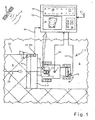
- Fig. 1 shows an executed as a combine harvester 2 agricultural machine 1 which is assigned in its front area designed as a grain cutting unit 3 attachment 4 for harvesting a grown in a territory to be processed 5 stock 6.
- the harvester 2 has one known GPS locating device 7, which receives position signals 9 generated by so-called GPS satellites 8 and generates them from these position signals 10 of the combine harvester 2.
- at least one control and evaluation unit 12 is arranged in the effective range of the operator 13, which according to its schematic enlargement in FIG Fig. 1 at least one display unit 14, an input unit 15 and a programming module 16 includes.
- the combine harvester 2 has a steering system 19 which can be controlled automatically so that the combine harvester 2 in the territory 5 to be processed automatically moves on predefined driving routes 20 can.
- this automatic guidance of the agricultural working machine can be effected by depositing the travel routes 20 to be processed in the control and evaluation unit 12, the generation of which being effected either externally or in the control and evaluation unit 12 itself External route signals 21 then usually passed by femübertragung to the control and evaluation unit 12.
- the position signals 10 of the combine harvester 2 generated by the GPS locating device 7 so-called steering signals 22 are then generated in the control and evaluation unit 12 and transmitted to the steering system 19, so that the agricultural work machine 1 automatically moves on a defined route 20 in the road to be processed
- the position signals 10 of the agricultural working machine 1 in the territory 5 to be processed can also be generated by optoelectronic locating devices 23, such as a laser scanner 24 detecting a crop edge 25.
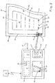
- the territory to be processed 5 may have any desired outer contours 26, wherein the travel routes 20 to be traveled by the agricultural machine 1 should be selected as a function of the working width X of the agricultural machine 1 such that adjacent travel routes 20 are at a distance from each other that corresponds to the working width X the agricultural machine corresponds to 1,
- the in FIG. 2 shown in phantom The outermost travel route 20 must first be determined either by driving around the territory 5 to be processed once, or, if it has already been traveled and created earlier, can be transferred directly to the control and evaluation unit 12 of the combine harvester 2 via the external route signals 21.
- the agricultural working machine 1 may be necessary for the agricultural working machine 1 to process a plurality of travel routes 20 simulating the outer contour 26 of the territory 5 to be processed.
- at least the internal driving routes 20 can be processed automatically.
- very different lane geometries and Fahrspuran extracten arise. This is where the invention begins.
- An optimal arrangement of the lanes in a territory to be processed 5 for example, be structured so that after one or more the outer contour 26 of the territory to be processed 5 imitating arranged in the so-called headland 27 routes 20, the remaining remaining territory 28 by differently running lanes 29 more efficiently cross over and editable, To generate these routes 29, it first requires a so-called reference line 30, which defines the orientation of the new routes to be generated 29 in the territory to be processed 5.
- this reference line 30 is generated by the fact that while the agricultural machine 1 is automatically guided along an outer, the outer contour 26 of the territory to be machined replicating route 5 20, the operator 13 of the agricultural machine 1 by pressing a start button 31 and a stop button 32 can activate and stop a recording mode 33 associated with the navigation module 18.
- the contour of the distance traveled in this period by the agricultural machine 1 travel route 20 is recorded as a new reference line 30 and stored in the programming module 16.
- the operation of the start button 31 and the stop button 32 leads to the generation of so-called start points 34 and End points 35, which are at least stored and can be visualized in an advantageous embodiment of the invention in the display unit 14.
- the display unit 14 is a so-called touch screen monitor 36 comprises on which the operator 13 in the depicted route 20 can directly select the starting point 34 and the end point 35 of the reference line 30 to be generated, without having to activate operation buttons 31, 32.
- the storage of the recorded reference line 30 can also be transmitted to a central processing unit 37.
- FIG. 3 the principle of route generation and the required structure of the programming module 16 is explained in more detail with reference to a schematic representation, in the lower part of the FIG. 3
- the territory to be processed 5 and the executed as a combine harvester 2 agricultural machine 1 and the processed, differently structured routes 20, are shown.
- the upper part of the FIG. 3 shows an enlarged view of the control and evaluation unit 12 with a schematic detail representation of the data generation.
- the control and evaluation unit 12 comprises a display unit 14, an input unit 15 and a programming module 16.
- at least one route planning system module 17 and the navigation module 18 according to the invention are set up in the programming module 16. They are out FIG. 3 resulting rigidity between navigation module 18 and route planning system module 17 has been selected for reasons of better representability. It is within the scope of the invention that these are combined in a single module in the programming module 16.
- Automatic driving modes 39-41 and at least one recording mode 33 for recording a reference line 30 are stored in the navigation module 18 in the exemplary embodiment.
- the automatic driving modes 39-41 comprise in the exemplary embodiment shown a first automatic driving mode "driving off a straight distance limited by a starting point and an end point” 39 , a second automatic driving mode “departing one from a starting point and an ending point limited contour distance "40 and another automatic driving mode” contour travel without limitation by a starting point and an end point "41.
- the very concept of the automatic driving modes 39-41 indicates their structure, namely the automatic driving modes 39 and 40 automatically guide the agricultural vehicle 1 to driving routes 20 which are determined by predefined starting points 43 and end points 44, wherein the travel route 20 is designed either as a straight route or a curved contour route, in contrast to which the further automatic driving mode 41 operates in such a way that initially a first, for example the outer contour 26 of the territory 5 to be processed replicating outer route 20 is traveled by the agricultural machine 1, this outer, route 20 depending on whether their geodata is present or not automatically or controlled by the operator 13.
- the respective automatic mode 39-41 can be selected by selector switch 45-47.
- the recording mode 33 which is likewise integrated into the navigation module 18, can be activated and terminated on a touchscreen monitor 36, for example via start and stop buttons 31, 32 or by definition of the start and end points 34, 35 of the reference line 30.
- the use of a touch screen monitor 36 also has the advantage that the selection of a reference line 30 can be made at any time, if on the touch screen monitor 36, a plurality of already processed and / or still to be processed routes 20, 29 are displayed.
- the various automatic driving modes 39-41 are linked to the recording mode 33 such that on the one hand the recording according to the invention of a reference line 30 in any of the available automatic driving modes 39-41 or on the other hand regardless of whether one of the available automatic driving modes 39-41 activated is possible.
- the recording mode 33 can be started in a first automatic driving mode 39-41 and generates a reference line 30, which is then used to create driving routes 29 for another than the automatic driving mode 39-41 active during the recording.
- the recording mode 33 may be started, and a reference line 30 record, which is then used to generate routes 29 for the automatic driving mode "departing from a start point and an end point limited straight line” 39.
- the recording mode 33 By defining a starting point 34 and an end point 35 for recording the reference line 30 during the contouring in the manner already described, the recording mode 33 generates a straight line between these points 34, 35 as the reference line 30.
- the agricultural working machine 1 would be operated in the third automatic driving mode 41 for processing the travel route 20 defining the outer contour 26 of the territory 5 to be processed. It is within the scope of the invention that the agricultural machine 1 but also in one of the other automatic driving modes 39, 40 can be operated or that can be changed during operation in the one automatic mode 39-41 in another automatic mode 39-41.
- the operator 13 of the combine harvester 2 activates the start key 31 to define the starting point 34 of the record.
- the stop button 32 is pressed so that the recording is aborted by defining an end point 35.
- the distance lying between the start and end points 34, 35 forms the reference line 30, which is stored in the simplest case in the control and evaluation unit 12 and forms the input information 48 for the route planning system 17 according to the invention.
- the route planning system 17 includes a so-called Beetfunktionsmodul 49 in which based on the generated reference line 30 a remaining territory to be processed 28 filled with routes 29 and stored in a so-called bed function 50.
- the processing of the now stored bedding function 50 can be done either by targeted retrieval or the fact that the operator 13 the agricultural machine 1 parallel to the location of the generated reference line 30 into the stock 6 and the programming module 16 automatically recognizes that now the recorded bed function 50 to work off is.
- each bedding function 50 can be stored in the programming module 16 and each bedding function 50 comprises differently structured travel routes 20, 29.
- the different structure of the routes 20, 29 can thereby both the shape, such as straight or curved lines, and the location in the territory to be processed 5, such as the north-south-east-west arrangement include.
Abstract
Description
Die Erfindung betrifft ein Routenplanungssystem für landwirtschaftliche Arbeitsmaschinen nach dem Oberbegriff des Anspruchs 1.The invention relates to a route planning system for agricultural machines according to the preamble of claim 1.
Aus dem Stand der Technik sind eine Vielzahl von gattungsgemäßen Routenplanungssystemen bekannt, die neben der Aufzeichnung von Fahrtrouten eines über ein zu bearbeitendes Territorium bewegten Fahrzeuges auch das automatische Abarbeiten zuvor programmierter Fahrtrouten durch das besagte Fahrzeug umfassen. Beispielsweise beschreibt die
Ein heute typischerweise eingesetztes Verfahren einer Routenplanung im Zusammenhang mit sogenannten automatischen Spurführungssystemen ist unter anderem in der
Aus der
Es ist deshalb Aufgabe der Erfindung die beschriebenen Nachteile des Standes der Technik zu vermeiden und ein Routenplanungssystem vorzuschlagen, welches schnell und hochpräzise Fahrtrouten einem zu bearbeitendes Territorium zuordnen kann, sodass sich der Aufwand für die Erstellung dieser Fahrtrouten erheblich reduziert.It is therefore an object of the invention to avoid the disadvantages of the prior art described and to propose a route planning system, which can quickly and highly accurate routes assign a territory to be processed, so that the cost of creating these routes significantly reduced.
Diese Aufgabe wird erfindungsgemäß durch die kennzeichnenden Merkmale des Anspruchs 1 gelöst.This object is achieved by the characterizing features of claim 1.
Indem das Routenplanungssystem ein Navigationsmodul beinhaltet, welches ein oder mehrere Automatikfahrmodi und zumindest einen Aufzeichnungsmodus umfasst und der oder die Automatikfahrmodi und der zumindest eine Aufzeichnungsmodus unabhängig voneinander aktivierbar sind, wird sichergestellt, dass die landwirtschaftliche Arbeitsmaschine im Automatikfahrmodus betrieben werden kann und zugleich die Aufzeichnung einer Referenzlinie für einen zukünftig abzuarbeitenden Automatikmodus aufgezeichnet wird. Damit wird zeitgleich eine bereits existierende Fahrtroute abgearbeitet und eine neue, zukünftig benötigte Fahrtroute erstellt, sodass sich der Aufwand für die Erstellung von Fahrtrouten eines Routenplanungssystems erheblich reduziert.By the route planning system includes a navigation module, which comprises one or more automatic driving modes and at least one recording mode and the automatic driving modes and the at least one recording mode are independently activated, it is ensured that the agricultural machine can be operated in automatic driving mode and at the same time recording a reference line is recorded for an automatic mode to be processed in the future. At the same time an already existing route is processed and a new, future required route is created, so that the effort for the creation of routes of a route planning system is significantly reduced.
In vorteilhafter Ausgestaltung der Erfindung wird in einem Automatikfahrmodus die Aufzeichnung einer definierten Fahrstrecke vorgenommen, die zugleich die Referenzlinie einer oder mehrerer nachfolgend abzuarbeitenden Fahrstrecken bildet. Dies hat insbesondere den Vorteil, dass die Routenplanung auf Basis sehr präziser Daten des zu bearbeitenden Territoriums vorgenommen wird und die Generierung dieser präzisen sogenannten Online-Daten keine unproduktiven Hilfsfahrten zur Definition benötigter Referenzpunkte des zu bearbeitenden Territoriums erfordern.In an advantageous embodiment of the invention, the recording of a defined route is made in an automatic driving mode, which is also the reference line one or more subsequently processed routes. This has the particular advantage that the route planning is carried out on the basis of very precise data of the territory to be processed and the generation of these precise so-called online data does not require unproductive auxiliary trips to define required reference points of the territory to be processed.
In einer weiteren vorteilhaften Ausgestaltung der Erfindung werden die von der Referenzlinie definierten, nachfolgend abzuarbeitenden Fahrstrecken in einem Beetfunktionsmodul als Beetfunktion zusammengefasst. Damit wird gewährleistet, dass die Aufteilung des nachfolgend zu bearbeitenden Territoriums oder eines Ausschnitts dieses Territoriums mit definierten Fahrtrouten bereits vollständig abgeschlossen sein kann, bevor die Bearbeitung des momentan von dem Fahrzeug bearbeiteten Territoriums abgeschlossen ist.In a further advantageous embodiment of the invention, the routes defined by the reference line and subsequently to be processed are combined in a bed function module as a bed function. This ensures that the division of the territory to be subsequently processed or a section of this territory with defined routes can already be completed before the processing of the territory currently being processed by the vehicle is completed.
Eine vorteilhafte Weiterbildung der Erfindung ergibt sich dann, wenn die definierte Fahrstrecke durch Selektion eines die definierte Fahrstrecke begrenzenden Anfangspunktes und Endpunktes erfolgt Auf diese Weise kann der Betreiber des Fahrzeugs ohne große Mühe die Gestalt der neuen Referenzlinie definieren. In einer sehr einfachen Ausgestaltung wird dies dadurch erreicht, dass der Anfangspunkt und der Endpunkt durch Generierung eines Start- und Stoppsignals in einer Aufzeichnungseinheit selektiert werden. Eine noch einfachere Handhabung ergibt sich dann, wenn in vorteilhafter Ausgestaltung der Erfindung die Steuer- und Auswerteinheit eine als Touchscreenmonitor ausgebildete Anzeigeeinheit umfasst und dass der Anfangspunkt und der Endpunkt durch Selektion auf dem Touchscreenmonitor bestimmt werden, Auf diese Weise ist der Betreiber auch in der Wahl einer geeigneten Referenzlinie völlig frei, da auf dem Bildschirm ein beliebiger Streckenabschnitt als neue Referenzlinie definiert werden kann.An advantageous development of the invention results when the defined route is selected by selecting a defined driving distance limiting start point and end point in this way, the operator of the vehicle without much effort to define the shape of the new reference line. In a very simple embodiment, this is achieved by selecting the starting point and the end point by generating a start and stop signal in a recording unit. An even easier handling results when, in an advantageous embodiment of the invention, the control and evaluation unit comprises a display unit designed as a touchscreen monitor and that the starting point and the end point are determined by selection on the touchscreen monitor, in this way, the operator is also in the election a suitable reference line completely free, since on the screen any section can be defined as a new reference line.
In vorteilhafter Ausgestaltung der Erfindung umfasst die Beetfunktion die Aufteilung eines zu bearbeitenden Territoriums in eine Vielzahl von Fahrstrecken, sodass in einem einzigen Schritt ein beliebig großes, zu bearbeitendes Territorium in Fahrstrecken unterteilt werden kann.In an advantageous embodiment of the invention, the bedding function comprises the division of a territory to be processed in a plurality of routes, so that in a single step, an arbitrarily large, to be processed territory can be divided into routes.
Ein besonders flexibler Einsatz des erfindungsgemäßen Routenplanungssystems ergibt sich dann, wenn die Automatikfahrmodi das Abfahren einer von einem Anfangspunkt und einem Endpunkt begrenzten geraden Strecke, das Abfahren einer von einem Anfangspunkt und einem Endpunkt begrenzten Konturstrecke und das Konturfahren ohne Begrenzung durch einen Anfangspunkt und einen Endpunkt oder eine Kombination aus zumindest diesen Automatikfahrmodi umfassen. Diese Flexibilität des Routenplanungssystems wird auch dadurch noch erhöht, wenn der jeweilige Automatikfahrmodus frei wählbar ist und zwischen verschiedenen Automatikfahrmodi umgeschaltet werden kann.A particularly flexible use of the route planning system according to the invention results when the automatic driving modes driving off a limited from a starting point and an end point straight line, the departure of a limited by a starting point and an end point contour line and the contour driving without limitation by a start point and an end point or a combination of at least these automatic driving modes include. This flexibility of the route planning system is also increased by the fact that the respective automatic driving mode is freely selectable and can be switched between different automatic driving modes.
Eine weitere vorteilhafte Ausgestaltung der Erfindung ergibt sich dann, wenn in dem einen Automatikfahrmodus die Aufzeichnung einer definierten Fahrstrecke erfolgt und diese definierte Fahrstrecke die Referenzlinie für die Beetfunktion eines anderen Automatikfahrmodus bildet. Dies hat insbesondere den Vorteil, dass in jedem beliebigen Automatikfahrmodus eine Referenzlinie beliebigster Struktur generiert werden kann, sodass die Methode zur Generierung der Referenzlinie sehr flexibel einsetzbar ist.A further advantageous embodiment of the invention results when the recording of a defined route takes place in the one automatic driving mode and this defined route forms the reference line for the bed function of another automatic driving mode. This has the particular advantage that in any automatic driving mode a reference line of most arbitrary structure can be generated, so that the method for generating the reference line can be used very flexibly.
Weitere vorteilhafte Ausführungen sind Gegenstand weiterer Unteransprüche und werden nachfolgend an Hand eines in mehreren Figuren dargestellten Ausführungsbeispiels beschrieben. Es zeigen:
- Fig. 1
- die Draufsicht auf eine landwirtschaftliche Arbeitsmaschine mit Detailansicht der erfindungsgemäßen Steuer- und Auswerteinheit
- Fig. 2
- eine schematische Darstellung des erfindungsgemäßen Routenplanungssys- tems
- Fig. 3
- eine schematische Darstellung der Steuer- und Auswerteinheit mit erfindungs- gemäßem Programmiermodul
- Fig. 1
- the top view of an agricultural machine with detailed view of the control and evaluation unit according to the invention
- Fig. 2
- a schematic representation of the route planning system according to the invention
- Fig. 3
- a schematic representation of the control and evaluation unit with inventive programming module
Gemäß
äußerste Fahrtroute 20 muss entweder durch einmaliges Umfahren des zu bearbeitenden Territoriums 5 zunächst ermittelt werden oder kann, sofern früher schon einmal abgefahren und erstellt, via der externen Fahrtroutensignale 21 an die Steuerund Auswerteinheit 12 des Mähdreschers 2 unmittelbar übergeben werden. Je nach Beschaffenheit des zu bearbeitenden Territoriums 5 und der Größe der landwirtschaftlichen Arbeitsmaschine 1 kann es erforderlich sein, dass die landwirtschaftliche Arbeitsmaschine 1 mehrere die Außenkontur 26 des zu bearbeitenden Territoriums 5 nachbildende Fahrtrouten 20 abarbeitet. In diesem Fall können zumindest die innen liegenden Fahrtrouten 20 automatisch abgearbeitet werden. In Abhängigkeit von der Außenkontur 26 des zu bearbeitenden Territoriums 5 können sich, wie bereits aus
The
In dem Navigationsmodul 18 sind in erfindungsgemäßer Weise Automatikfahrmodi 39-41 und zumindest ein Aufzeichnungsmodus 33 zur Aufzeichnung einer Referenzlinie 30 hinterlegt Die Automatikfahrmodi 39-41 umfassen in dem dargestellten Ausführungsbeispiel einen ersten Automatikfahrmodus "Abfahren einer von einem Anfangspunkt und einem Endpunkt begrenzten geraden Strecke" 39, einen zweiten Automatikfahrmodus "Abfahren einer von einem Anfangspunkt und einem Endpunkt
begrenzten Konturstrecke" 40 und einen weiteren Automatikfahrmodus "Konturfahrt ohne Begrenzung durch einen Anfangspunkt und einen Endpunkt" 41. Bereits die Begrifflichkeit der Automatikfahrmodi 39-41 weist auf deren Struktur hin, nämlich die Automatikfahrmodi 39 und 40 führen das landwirtschaftliche Fahrzeug 1 automatisch auf Fahrtrouten 20, die durch vordefinierte Anfangspunkte 43 und Endpunkte 44 bestimmt sind, wobei die Fahrtroute 20 entweder als gerade Strecke oder gekrümmte Konturstrecke ausgebildet ist. Demgegenüber arbeitet der weitere Automatikfahrmodus 41 in der Weise, dass zunächst eine erste, beispielsweise die Außenkontur 26 des zu bearbeitenden Territoriums 5 nachbildende äußere Fahrtroute 20 von der landwirtschaftlichen Arbeitsmaschine 1 abgefahren wird, wobei dieser äußeren, Fahrtroute 20 in Abhängigkeit davon, ob deren Geodaten vorliegen oder nicht automatisch oder vom Betreiber 13 gesteuert gefolgt wird. Im dargestellten Ausführungsbeispiel kann der jeweilige Automatikfahrmodus 39-41 durch Vorwahlschalter 45-47 ausgewählt werden. Wie bereits beschrieben, kann der ebenfalls in das Navigationsmodul 18 integrierte Aufzeichnungsmodus 33 beispielsweise über Start- und Stopptasten 31, 32 oder durch Definition des Anfangs- und Endpunktes 34, 35 der Referenzlinie 30 auf einem Touchscreenmonitor 36 aktiviert und beendet werden. Der Einsatz eines Touchscreenmonitors 36 hat zudem den Vorteil, dass die Selektion einer Referenzlinie 30 dann zu jedem beliebigen Zeitpunkt vorgenommen werden kann, wenn auf dem Touchscreenmonitor 36 eine Vielzahl von bereits abgearbeiteten und/oder noch abzuarbeitenden Fahrtrouten 20, 29 angezeigt werden. In einer vorteilhaften Ausgestaltung der Erfindung sind die verschiedenen Automatikfahrmodi 39-41 so mit dem Aufzeichnungsmodus 33 verknüpft, dass einerseits die erfindungsgemäße Aufzeichnung einer Referenzlinie 30 in irgendeinem der verfügbaren Automatikfahrmodi 39-41 oder andererseits unabhängig davon, ob einer der verfügbaren Automatikfahrmodi 39-41 aktiviert ist erfolgen kann. Auf diese Weise wird es möglich, dass der Aufzeichnungsmodus 33 in einem ersten Automatikfahrmodus 39-41 gestartete werden kann und eine Referenzlinie 30 generiert, die dann zur Erstellung von Fahrtrouten 29 für einen anderen als den während der Aufzeichnung aktiven Automatikfahrmodus 39-41 herangezogen wird. Beispielsweise kann der Aufzeichnungsmodus 33 während die landwirtschaftliche Arbeitsmaschine 1 in dem Automatikfahrmodus "Konturfahrt ohne Begrenzung durch einen Anfangspunkt und einen Endpunkt" 41 betrieben wird gestartet werden und eine Referenzlinie 30 aufzeichnen, die dann zur Generierung von Fahrtrouten 29 für den Automatikfahrmodus "Abfahren einer von einem Anfangspunkt und einem Endpunkt begrenzten geraden Strecke" 39 herangezogen wird. Indem während der Konturfahrt in der bereits beschriebenen Weise ein Anfangspunkt 34 und ein Endpunkt 35 zur Aufzeichnung der Referenzlinie 30 definiert werden, generiert der Aufzeichnungsmodus 33 eine zwischen diesen Punkten 34, 35 liegende gerade Strecke als Referenzlinie 30.Automatic driving modes 39-41 and at least one
limited contour distance "40 and another automatic driving mode" contour travel without limitation by a starting point and an end point "41. The very concept of the automatic driving modes 39-41 indicates their structure, namely the
Im dargestellten Ausführungsbeispiel nach
Es liegt im Rahmen des Könnens eines Fachmanns das beschriebene Routenplanungssystem 17 in nicht dargestellter Weise abzuwandeln oder in anderen Maschinensystemen einzusetzen, um die beschriebenen Effekte zu erzielen, ohne dabei den Rahmen der Erfindung zu verlassen.It is within the skill of one skilled in the art to modify the described
- 11
- landwirtschaftliche Arbeitsmaschineagricultural working machine
- 22
- MähdrescherHarvester
- 33
- GetreideschneidwerkGrain header
- 44
- Vorsatzgerätheader
- 55
- Territoriumterritory
- 66
- BestandDuration
- 77
- GPS-OrtungsvorrichtungGPS tracking device
- 88th
- GPS-SatellitGPS satellite
- 99
- Positionssignalposition signal
- 10 110 1
- Positionssignal FahrerkabinePosition signal of the driver's cab
- 1212
- Steuer- und AuswerteinheitControl and evaluation unit
- 1313
- Betreiberoperator
- 1414
- Anzeigeeinheitdisplay unit
- 1515
- Eingabeeinheitinput unit
- 1616
- Programmiermodulprogramming module
- 1717
- RoutenplanungssystemRoute planning system
- 1818
- Navigationsmodulnavigation module
- 1919
- Lenksystemsteering system
- 2020
- Fahrtrouteroute
- 2121
- FahrtroutensignalRoute signal
- 2222
- Lenksignalsteering signal
- 2323
- Ortungsvorrichtunglocating device
- 2424
- Laserscannerlaser scanner
- 2525
- Bestandskantecrop edge
- 2626
- Außenkonturouter contour
- 2727
- Vorgewendeheadland
- 2828
- Restterritoriumrest territory
- 2929
- Fahrtrouteroute
- 3030
- Referenzliniereference line
- 3131
- Starttastestart button
- 3232
- Starttastestart button
- 3333
- Aufzeichnungsmodusrecording mode
- 3434
- Anfangspunktstarting point
- 3535
- Endpunktendpoint
- 3636
- Touchscreenmonitortouchscreen monitor
- 3737
-
zentrale Recheneinheit
38central processing unit
38 - 3939
- AutomatikfahrmodusAutomatic driving mode
- 4040
- AutomatikfahrmodusAutomatic driving mode
- 4141
-
Automatikfahrmodus
42Automatic driving mode
42 - 4343
- Anfangspunktstarting point
- 4444
- Endpunktendpoint
- 4545
- Vorwahlschalterselector switch
- 4646
- Vorwahlschalterselector switch
- 4747
- Vorwahlschalterselector switch
- 4848
- Eingangsinformationinput information
- 4949
- BeetfunktionsmodulBeetfunktionsmodul
- 5050
- Beetfunktioncrop bed function
- XX
- Arbeitsbreiteworking width
Claims (10)
- A route planning system (17) for agricultural working machines (1), wherein associated with the agricultural working machine (1) is a defined working width (X) for generating travel routes (20, 29) in a territory (5) and generation of the travel routes (20, 29) is effected in a navigation module (18), wherein the navigation module (18) includes at least one automatic travel mode (39-41) for automatically guiding the agricultural working machine (1) on travel routes (20, 29) and at least one recording mode (33) for recording a reference line (30),
characterised in that
the navigation module (18) includes one or more automatic travel modes (39-41) and wherein the automatic travel mode or modes (39-41) and the at least one recording mode (33) are activatable independently of each other. - A route planning system for agricultural working machines according to claim 1 characterised in that recording of a defined travel path (20) is effected in an automatic travel mode (39-41) and said defined travel path (20) forms the reference line (30) of one or more travel paths (29) to be subsequently processed.
- A route planning system for agricultural working machines according to claim 2 characterised in that the travel paths (29) defined by the reference line (30) and to be subsequently processed are assembled in a crop bed function module (49) as a bed function (50).
- A route planning system for agricultural working machines according to one of the preceding claims characterised in that the defined travel path (20, 30) is effected by selection of a start point (34) and an end point (35) delimiting the defined travel path (20, 30).
- A route planning system for agricultural working machines according to one of the preceding claims characterised in that the start point (34) and the end point (35) are selected by generating a start and stop signal (31, 32) in a control and evaluation unit (12).
- A route planning system for agricultural working machines according to claim 5 characterised in that the control and evaluation unit (12) includes a display unit (14) in the form of a touch screen monitor (36) and the start point and the end point (35) are determined by selection on the touch screen monitor (36).
- A route planning system for agricultural working machines according to claim 3 characterised in that the bed function (50) includes division of a territory (5, 28) to be worked into a plurality of travel paths (20, 29).
- A route planning system for agricultural working machines according to one of the preceding claims characterised in that the automatic travel modes (39-41) include travelling along a straight path delimited by a start point (43) and an end point (44), travelling along a contour path delimited by a start point (43) and an end point (44) and contour travel without limitation by a start point (43) and an end point (44) or a combination of at least said automatic travel modes (39-41).
- A route planning system for agricultural working machines according to one of the preceding claims characterised in that the respective automatic travel mode (39-41) can be freely selected and switching-over can be effected between various automatic travel modes (39-41).
- A route planning system for agricultural working machines according to one of the preceding claims characterised in that recording of a defined travel path (20) is effected in the one automatic travel mode (39-41) and said defined travel path (20) forms the reference line (30) for the bed function (50) of another automatic travel mode (39-41).
Applications Claiming Priority (1)
| Application Number | Priority Date | Filing Date | Title |
|---|---|---|---|
| DE102006002567A DE102006002567A1 (en) | 2006-01-18 | 2006-01-18 | Method of generating reference lanes for agricultural vehicles |
Publications (2)
| Publication Number | Publication Date |
|---|---|
| EP1811268A1 EP1811268A1 (en) | 2007-07-25 |
| EP1811268B1 true EP1811268B1 (en) | 2011-01-19 |
Family
ID=37909335
Family Applications (1)
| Application Number | Title | Priority Date | Filing Date |
|---|---|---|---|
| EP06124116A Active EP1811268B1 (en) | 2006-01-18 | 2006-11-15 | Route planning system for generating reference tracks for agricultural working machines |
Country Status (6)
| Country | Link |
|---|---|
| US (1) | US7729834B2 (en) |
| EP (1) | EP1811268B1 (en) |
| AT (1) | ATE496280T1 (en) |
| DE (2) | DE102006002567A1 (en) |
| RU (1) | RU2412580C2 (en) |
| UA (1) | UA95440C2 (en) |
Families Citing this family (29)
| Publication number | Priority date | Publication date | Assignee | Title |
|---|---|---|---|---|
| US8060299B2 (en) * | 2007-02-28 | 2011-11-15 | Caterpillar Inc. | Machine with automated steering system |
| AU2010212148B2 (en) | 2009-02-06 | 2014-07-10 | Bae Systems Plc | Touch -screen vehicle remote control |
| DE102009009818A1 (en) | 2009-02-20 | 2010-08-26 | Claas Selbstfahrende Erntemaschinen Gmbh | Method for generating reference lanes for agricultural vehicles |
| RU2455660C1 (en) * | 2011-03-24 | 2012-07-10 | Государственное научное учреждение Всероссийский научно-исследовательский институт агрохимии им. Д.Н. Прянишникова | Method of accelerated identification of stable internal field contours of soil fertility in agricultural fields |
| DE102011054630A1 (en) * | 2011-10-20 | 2013-04-25 | Claas Agrosystems GmbH | visualiser |
| US8589013B2 (en) | 2011-10-25 | 2013-11-19 | Jaybridge Robotics, Inc. | Method and system for dynamically positioning a vehicle relative to another vehicle in motion |
| DE102013107492A1 (en) | 2013-07-15 | 2015-01-15 | Koubachi AG | System for monitoring and controlling activities of at least one gardening tool within at least one activity area |
| US9188986B2 (en) | 2013-10-01 | 2015-11-17 | Jaybridge Robotics, Inc. | Computer-implemented method and system for dynamically positioning a vehicle relative to another vehicle in motion for on-the-fly offloading operations |
| CN105980948B (en) * | 2014-02-06 | 2019-12-31 | 洋马株式会社 | Method for setting travel route of autonomous travel work vehicle |
| DE102014102489A1 (en) * | 2014-02-26 | 2015-08-27 | Amazonen-Werke H. Dreyer Gmbh & Co. Kg | control unit |
| DE102014104619A1 (en) | 2014-04-02 | 2015-10-08 | Claas Agrosystems Kgaa Mbh & Co. Kg | Planning system and method for planning fieldwork |
| JP6467897B2 (en) * | 2014-12-10 | 2019-02-13 | 井関農機株式会社 | Tractor |
| RU2644953C2 (en) * | 2015-06-23 | 2018-02-15 | Общество с ограниченной ответственностью "Комбайновый завод "Ростсельмаш" | Harvester cabin |
| US9663921B2 (en) * | 2015-07-09 | 2017-05-30 | Caterpillar Inc. | System and method for controlling operations of a machine |
| US9795074B2 (en) * | 2015-10-27 | 2017-10-24 | Cnh Industrial America Llc | Automatic swath generation device and methods |
| US9826673B1 (en) * | 2016-05-27 | 2017-11-28 | Cnh Industrial America Llc | Swath acquisition system for an agricultural vehicle |
| DE102016110553A1 (en) | 2016-06-08 | 2017-12-14 | S&P Agrarsysteme GmbH | Method and arrangement for collecting data in agriculture |
| US10831213B2 (en) * | 2018-03-30 | 2020-11-10 | Deere & Company | Targeted loading assistance system |
| CN108303963A (en) * | 2018-04-04 | 2018-07-20 | 湖南丰茂植保机械有限公司 | A kind of Intelligent unattended driving equipment for plant protection earth station system |
| JP7014687B2 (en) * | 2018-08-07 | 2022-02-01 | 株式会社クボタ | Harvester |
| JP7237788B2 (en) * | 2019-09-26 | 2023-03-13 | 株式会社クボタ | work vehicle |
| JP7275012B2 (en) * | 2019-11-29 | 2023-05-17 | 株式会社クボタ | Automatic travel control system and combine |
| JP7201572B2 (en) * | 2019-11-29 | 2023-01-10 | 株式会社クボタ | automatic driving system |
| JP7403323B2 (en) * | 2020-01-14 | 2023-12-22 | 株式会社クボタ | Driving route management system |
| JP7388929B2 (en) * | 2020-01-14 | 2023-11-29 | 株式会社クボタ | agricultural vehicle |
| AT523999A1 (en) * | 2020-06-19 | 2022-01-15 | Ideas Gmbh & Co Kg | Device on agricultural machines for scanning contours and method for controlling the agricultural machine |
| JP7063365B2 (en) * | 2020-11-19 | 2022-05-09 | 井関農機株式会社 | Work vehicle |
| JP7386403B2 (en) * | 2021-05-27 | 2023-11-27 | 井関農機株式会社 | work vehicle |
| JP7371667B2 (en) * | 2021-05-27 | 2023-10-31 | 井関農機株式会社 | work vehicle |
Family Cites Families (12)
| Publication number | Priority date | Publication date | Assignee | Title |
|---|---|---|---|---|
| JP3673285B2 (en) * | 1992-10-09 | 2005-07-20 | 櫻護謨株式会社 | Outdoor work automation system |
| DE4342171C2 (en) | 1993-07-17 | 1996-01-25 | Georg Duerrstein | Soil preparation methods, in particular for fertilizing agricultural land |
| US5991694A (en) * | 1995-11-13 | 1999-11-23 | Caterpillar Inc. | Method and apparatus for determining the location of seedlings during agricultural production |
| DE19629618A1 (en) * | 1996-07-23 | 1998-01-29 | Claas Ohg | Route planning system for agricultural work vehicles |
| US6085130A (en) * | 1998-07-22 | 2000-07-04 | Caterpillar Inc. | Method and apparatus for selecting a transition scheme for use in transitioning a mobile machine from a first path to a second path |
| US6112143A (en) * | 1998-08-06 | 2000-08-29 | Caterpillar Inc. | Method and apparatus for establishing a perimeter defining an area to be traversed by a mobile machine |
| US6493374B1 (en) * | 1999-09-03 | 2002-12-10 | Cymer, Inc. | Smart laser with fast deformable grating |
| US6205381B1 (en) * | 1999-03-26 | 2001-03-20 | Caterpillar Inc. | Method and apparatus for providing autoguidance for multiple agricultural machines |
| US6236924B1 (en) * | 1999-06-21 | 2001-05-22 | Caterpillar Inc. | System and method for planning the operations of an agricultural machine in a field |
| US6643576B1 (en) * | 2000-11-15 | 2003-11-04 | Integrinautics Corporation | Rapid adjustment of trajectories for land vehicles |
| US6549849B2 (en) * | 2001-06-25 | 2003-04-15 | Trimble Navigation Ltd. | Guidance pattern allowing for access paths |
| US6681551B1 (en) * | 2002-07-11 | 2004-01-27 | Deere & Co. | Programmable function control for combine |
-
2006
- 2006-01-18 DE DE102006002567A patent/DE102006002567A1/en not_active Withdrawn
- 2006-11-15 DE DE502006008759T patent/DE502006008759D1/en active Active
- 2006-11-15 EP EP06124116A patent/EP1811268B1/en active Active
- 2006-11-15 AT AT06124116T patent/ATE496280T1/en active
-
2007
- 2007-01-15 US US11/623,123 patent/US7729834B2/en active Active
- 2007-01-15 RU RU2007101054/21A patent/RU2412580C2/en active
- 2007-01-17 UA UAA200700476A patent/UA95440C2/en unknown
Also Published As
| Publication number | Publication date |
|---|---|
| US7729834B2 (en) | 2010-06-01 |
| ATE496280T1 (en) | 2011-02-15 |
| US20070168116A1 (en) | 2007-07-19 |
| DE102006002567A1 (en) | 2007-08-02 |
| RU2007101054A (en) | 2008-07-27 |
| EP1811268A1 (en) | 2007-07-25 |
| DE502006008759D1 (en) | 2011-03-03 |
| UA95440C2 (en) | 2011-08-10 |
| RU2412580C2 (en) | 2011-02-27 |
Similar Documents
| Publication | Publication Date | Title |
|---|---|---|
| EP1811268B1 (en) | Route planning system for generating reference tracks for agricultural working machines | |
| EP1839479B1 (en) | Method for operating agricultural machinery | |
| EP1616470B1 (en) | Method and device for guiding an agricultural working vehicle | |
| EP3593613B1 (en) | Method for controlling a data transmission between an agricultural machine and an external transmit/receive unit | |
| EP1865396A2 (en) | Method and device for displaying vehicle movements | |
| EP2927767B1 (en) | Planning system and method for planning the treatment of a field | |
| EP2583544B1 (en) | Visualisation device | |
| DE102004027242A1 (en) | Route planning system for agricultural machines | |
| EP1847897A2 (en) | Method of controlling an agricultural machine | |
| EP2221702B1 (en) | Method for creating reference lanes for agricultural vehicles | |
| EP2125472B1 (en) | Semiautomatic parking machine | |
| EP1602267A2 (en) | Route planning system for agricultural working machines | |
| EP2452549B1 (en) | Method for tracking an agricultural work device | |
| EP1602560B1 (en) | Vehicle steering aid - apparatus and method | |
| EP2279467B1 (en) | Control method for a robot vehicle | |
| EP3468853B1 (en) | Proactive control of an assistance system of a motor vehicle | |
| EP1052143A2 (en) | Driving assistance for vehicle lane changing | |
| EP3363273A1 (en) | Agricultural machine system and method for planning lanes for processing an agricultural field | |
| EP2098439A2 (en) | Method and device for parking a vehicle in a space using a parking assist | |
| EP1533181B1 (en) | Device for the semiautomatique support for parking a vehicle | |
| EP1847898B1 (en) | Method for recording the path of travel of an agricultural machine | |
| DE10328395B4 (en) | Method for controlling an agricultural machine | |
| EP3251487A1 (en) | Method and device for controlling an agricultural distribution machine | |
| DE112018002405T5 (en) | OPERATING SUPPORT SYSTEM FOR WORKING MACHINE AND AGRICULTURAL SUPPORT SYSTEM | |
| DE102017202564A1 (en) | Method and device for determining a navigation route |
Legal Events
| Date | Code | Title | Description |
|---|---|---|---|
| PUAI | Public reference made under article 153(3) epc to a published international application that has entered the european phase |
Free format text: ORIGINAL CODE: 0009012 |
|
| AK | Designated contracting states |
Kind code of ref document: A1 Designated state(s): AT BE BG CH CY CZ DE DK EE ES FI FR GB GR HU IE IS IT LI LT LU LV MC NL PL PT RO SE SI SK TR |
|
| AX | Request for extension of the european patent |
Extension state: AL BA HR MK YU |
|
| AKX | Designation fees paid | ||
| 17P | Request for examination filed |
Effective date: 20080320 |
|
| RBV | Designated contracting states (corrected) |
Designated state(s): AT BE BG CH CY CZ DE DK EE ES FI FR GB GR HU IE IS IT LI LT LU LV MC NL PL PT RO SE SI SK TR |
|
| 17Q | First examination report despatched |
Effective date: 20080520 |
|
| GRAP | Despatch of communication of intention to grant a patent |
Free format text: ORIGINAL CODE: EPIDOSNIGR1 |
|
| RTI1 | Title (correction) |
Free format text: ROUTE PLANNING SYSTEM FOR GENERATING REFERENCE TRACKS FOR AGRICULTURAL WORKING MACHINES |
|
| GRAS | Grant fee paid |
Free format text: ORIGINAL CODE: EPIDOSNIGR3 |
|
| GRAA | (expected) grant |
Free format text: ORIGINAL CODE: 0009210 |
|
| AK | Designated contracting states |
Kind code of ref document: B1 Designated state(s): AT BE BG CH CY CZ DE DK EE ES FI FR GB GR HU IE IS IT LI LT LU LV MC NL PL PT RO SE SI SK TR |
|
| REG | Reference to a national code |
Ref country code: GB Ref legal event code: FG4D Free format text: NOT ENGLISH |
|
| REG | Reference to a national code |
Ref country code: CH Ref legal event code: EP |
|
| REG | Reference to a national code |
Ref country code: IE Ref legal event code: FG4D Free format text: LANGUAGE OF EP DOCUMENT: GERMAN |
|
| REF | Corresponds to: |
Ref document number: 502006008759 Country of ref document: DE Date of ref document: 20110303 Kind code of ref document: P |
|
| REG | Reference to a national code |
Ref country code: DE Ref legal event code: R096 Ref document number: 502006008759 Country of ref document: DE Effective date: 20110303 |
|
| REG | Reference to a national code |
Ref country code: NL Ref legal event code: VDEP Effective date: 20110119 |
|
| LTIE | Lt: invalidation of european patent or patent extension |
Effective date: 20110119 |
|
| PG25 | Lapsed in a contracting state [announced via postgrant information from national office to epo] |
Ref country code: SE Free format text: LAPSE BECAUSE OF FAILURE TO SUBMIT A TRANSLATION OF THE DESCRIPTION OR TO PAY THE FEE WITHIN THE PRESCRIBED TIME-LIMIT Effective date: 20110119 Ref country code: LV Free format text: LAPSE BECAUSE OF FAILURE TO SUBMIT A TRANSLATION OF THE DESCRIPTION OR TO PAY THE FEE WITHIN THE PRESCRIBED TIME-LIMIT Effective date: 20110119 Ref country code: IS Free format text: LAPSE BECAUSE OF FAILURE TO SUBMIT A TRANSLATION OF THE DESCRIPTION OR TO PAY THE FEE WITHIN THE PRESCRIBED TIME-LIMIT Effective date: 20110519 Ref country code: ES Free format text: LAPSE BECAUSE OF FAILURE TO SUBMIT A TRANSLATION OF THE DESCRIPTION OR TO PAY THE FEE WITHIN THE PRESCRIBED TIME-LIMIT Effective date: 20110430 Ref country code: GR Free format text: LAPSE BECAUSE OF FAILURE TO SUBMIT A TRANSLATION OF THE DESCRIPTION OR TO PAY THE FEE WITHIN THE PRESCRIBED TIME-LIMIT Effective date: 20110420 Ref country code: LT Free format text: LAPSE BECAUSE OF FAILURE TO SUBMIT A TRANSLATION OF THE DESCRIPTION OR TO PAY THE FEE WITHIN THE PRESCRIBED TIME-LIMIT Effective date: 20110119 |
|
| REG | Reference to a national code |
Ref country code: IE Ref legal event code: FD4D |
|
| PG25 | Lapsed in a contracting state [announced via postgrant information from national office to epo] |
Ref country code: PL Free format text: LAPSE BECAUSE OF FAILURE TO SUBMIT A TRANSLATION OF THE DESCRIPTION OR TO PAY THE FEE WITHIN THE PRESCRIBED TIME-LIMIT Effective date: 20110119 Ref country code: NL Free format text: LAPSE BECAUSE OF FAILURE TO SUBMIT A TRANSLATION OF THE DESCRIPTION OR TO PAY THE FEE WITHIN THE PRESCRIBED TIME-LIMIT Effective date: 20110119 Ref country code: FI Free format text: LAPSE BECAUSE OF FAILURE TO SUBMIT A TRANSLATION OF THE DESCRIPTION OR TO PAY THE FEE WITHIN THE PRESCRIBED TIME-LIMIT Effective date: 20110119 Ref country code: CY Free format text: LAPSE BECAUSE OF FAILURE TO SUBMIT A TRANSLATION OF THE DESCRIPTION OR TO PAY THE FEE WITHIN THE PRESCRIBED TIME-LIMIT Effective date: 20110119 Ref country code: SI Free format text: LAPSE BECAUSE OF FAILURE TO SUBMIT A TRANSLATION OF THE DESCRIPTION OR TO PAY THE FEE WITHIN THE PRESCRIBED TIME-LIMIT Effective date: 20110119 Ref country code: BG Free format text: LAPSE BECAUSE OF FAILURE TO SUBMIT A TRANSLATION OF THE DESCRIPTION OR TO PAY THE FEE WITHIN THE PRESCRIBED TIME-LIMIT Effective date: 20110419 |
|
| PG25 | Lapsed in a contracting state [announced via postgrant information from national office to epo] |
Ref country code: EE Free format text: LAPSE BECAUSE OF FAILURE TO SUBMIT A TRANSLATION OF THE DESCRIPTION OR TO PAY THE FEE WITHIN THE PRESCRIBED TIME-LIMIT Effective date: 20110119 Ref country code: IE Free format text: LAPSE BECAUSE OF FAILURE TO SUBMIT A TRANSLATION OF THE DESCRIPTION OR TO PAY THE FEE WITHIN THE PRESCRIBED TIME-LIMIT Effective date: 20110119 Ref country code: DK Free format text: LAPSE BECAUSE OF FAILURE TO SUBMIT A TRANSLATION OF THE DESCRIPTION OR TO PAY THE FEE WITHIN THE PRESCRIBED TIME-LIMIT Effective date: 20110119 |
|
| PLBE | No opposition filed within time limit |
Free format text: ORIGINAL CODE: 0009261 |
|
| STAA | Information on the status of an ep patent application or granted ep patent |
Free format text: STATUS: NO OPPOSITION FILED WITHIN TIME LIMIT |
|
| PG25 | Lapsed in a contracting state [announced via postgrant information from national office to epo] |
Ref country code: CZ Free format text: LAPSE BECAUSE OF FAILURE TO SUBMIT A TRANSLATION OF THE DESCRIPTION OR TO PAY THE FEE WITHIN THE PRESCRIBED TIME-LIMIT Effective date: 20110119 Ref country code: SK Free format text: LAPSE BECAUSE OF FAILURE TO SUBMIT A TRANSLATION OF THE DESCRIPTION OR TO PAY THE FEE WITHIN THE PRESCRIBED TIME-LIMIT Effective date: 20110119 Ref country code: RO Free format text: LAPSE BECAUSE OF FAILURE TO SUBMIT A TRANSLATION OF THE DESCRIPTION OR TO PAY THE FEE WITHIN THE PRESCRIBED TIME-LIMIT Effective date: 20110119 |
|
| 26N | No opposition filed |
Effective date: 20111020 |
|
| REG | Reference to a national code |
Ref country code: DE Ref legal event code: R097 Ref document number: 502006008759 Country of ref document: DE Effective date: 20111020 |
|
| PG25 | Lapsed in a contracting state [announced via postgrant information from national office to epo] |
Ref country code: MC Free format text: LAPSE BECAUSE OF NON-PAYMENT OF DUE FEES Effective date: 20111130 |
|
| REG | Reference to a national code |
Ref country code: CH Ref legal event code: PL |
|
| GBPC | Gb: european patent ceased through non-payment of renewal fee |
Effective date: 20111115 |
|
| PG25 | Lapsed in a contracting state [announced via postgrant information from national office to epo] |
Ref country code: CH Free format text: LAPSE BECAUSE OF NON-PAYMENT OF DUE FEES Effective date: 20111130 Ref country code: LI Free format text: LAPSE BECAUSE OF NON-PAYMENT OF DUE FEES Effective date: 20111130 |
|
| PG25 | Lapsed in a contracting state [announced via postgrant information from national office to epo] |
Ref country code: GB Free format text: LAPSE BECAUSE OF NON-PAYMENT OF DUE FEES Effective date: 20111115 |
|
| REG | Reference to a national code |
Ref country code: AT Ref legal event code: MM01 Ref document number: 496280 Country of ref document: AT Kind code of ref document: T Effective date: 20111115 |
|
| PG25 | Lapsed in a contracting state [announced via postgrant information from national office to epo] |
Ref country code: AT Free format text: LAPSE BECAUSE OF NON-PAYMENT OF DUE FEES Effective date: 20111115 |
|
| PG25 | Lapsed in a contracting state [announced via postgrant information from national office to epo] |
Ref country code: LU Free format text: LAPSE BECAUSE OF NON-PAYMENT OF DUE FEES Effective date: 20111115 |
|
| PG25 | Lapsed in a contracting state [announced via postgrant information from national office to epo] |
Ref country code: TR Free format text: LAPSE BECAUSE OF FAILURE TO SUBMIT A TRANSLATION OF THE DESCRIPTION OR TO PAY THE FEE WITHIN THE PRESCRIBED TIME-LIMIT Effective date: 20110119 |
|
| PG25 | Lapsed in a contracting state [announced via postgrant information from national office to epo] |
Ref country code: HU Free format text: LAPSE BECAUSE OF FAILURE TO SUBMIT A TRANSLATION OF THE DESCRIPTION OR TO PAY THE FEE WITHIN THE PRESCRIBED TIME-LIMIT Effective date: 20110119 |
|
| PG25 | Lapsed in a contracting state [announced via postgrant information from national office to epo] |
Ref country code: PT Free format text: LAPSE BECAUSE OF FAILURE TO SUBMIT A TRANSLATION OF THE DESCRIPTION OR TO PAY THE FEE WITHIN THE PRESCRIBED TIME-LIMIT Effective date: 20110119 |
|
| REG | Reference to a national code |
Ref country code: FR Ref legal event code: PLFP Year of fee payment: 10 |
|
| REG | Reference to a national code |
Ref country code: FR Ref legal event code: PLFP Year of fee payment: 11 |
|
| REG | Reference to a national code |
Ref country code: FR Ref legal event code: PLFP Year of fee payment: 12 |
|
| PGFP | Annual fee paid to national office [announced via postgrant information from national office to epo] |
Ref country code: BE Payment date: 20221118 Year of fee payment: 17 |
|
| P01 | Opt-out of the competence of the unified patent court (upc) registered |
Effective date: 20230515 |
|
| PGFP | Annual fee paid to national office [announced via postgrant information from national office to epo] |
Ref country code: IT Payment date: 20231124 Year of fee payment: 18 Ref country code: FR Payment date: 20231120 Year of fee payment: 18 Ref country code: DE Payment date: 20231121 Year of fee payment: 18 |
|
| PGFP | Annual fee paid to national office [announced via postgrant information from national office to epo] |
Ref country code: BE Payment date: 20231120 Year of fee payment: 18 |