EP1808864B1 - Verfahren zum Einsetzen eines Brennstofftabletten Sperrhalters in einem Kernbrennstab - Google Patents
Verfahren zum Einsetzen eines Brennstofftabletten Sperrhalters in einem Kernbrennstab Download PDFInfo
- Publication number
- EP1808864B1 EP1808864B1 EP07100174A EP07100174A EP1808864B1 EP 1808864 B1 EP1808864 B1 EP 1808864B1 EP 07100174 A EP07100174 A EP 07100174A EP 07100174 A EP07100174 A EP 07100174A EP 1808864 B1 EP1808864 B1 EP 1808864B1
- Authority
- EP
- European Patent Office
- Prior art keywords
- tube
- spring
- tool
- retainer spring
- diameter
- Prior art date
- Legal status (The legal status is an assumption and is not a legal conclusion. Google has not performed a legal analysis and makes no representation as to the accuracy of the status listed.)
- Active
Links
- 239000000446 fuel Substances 0.000 title claims description 67
- 239000008188 pellet Substances 0.000 title claims description 24
- 238000000034 method Methods 0.000 title claims description 15
- 239000003758 nuclear fuel Substances 0.000 title claims description 7
- 230000007704 transition Effects 0.000 claims description 20
- 230000036316 preload Effects 0.000 claims description 10
- 230000006835 compression Effects 0.000 claims description 5
- 238000007906 compression Methods 0.000 claims description 5
- 238000009434 installation Methods 0.000 description 10
- 238000003780 insertion Methods 0.000 description 3
- 230000037431 insertion Effects 0.000 description 3
- 238000011900 installation process Methods 0.000 description 3
- 238000003466 welding Methods 0.000 description 2
- 238000012938 design process Methods 0.000 description 1
- 230000014759 maintenance of location Effects 0.000 description 1
- 239000002184 metal Substances 0.000 description 1
- 230000035515 penetration Effects 0.000 description 1
- 238000007789 sealing Methods 0.000 description 1
- 239000007787 solid Substances 0.000 description 1
Images

Classifications
-
- G—PHYSICS
- G21—NUCLEAR PHYSICS; NUCLEAR ENGINEERING
- G21C—NUCLEAR REACTORS
- G21C3/00—Reactor fuel elements and their assemblies; Selection of substances for use as reactor fuel elements
- G21C3/02—Fuel elements
- G21C3/04—Constructional details
- G21C3/16—Details of the construction within the casing
- G21C3/18—Internal spacers or other non-active material within the casing, e.g. compensating for expansion of fuel rods or for compensating excess reactivity
-
- G—PHYSICS
- G21—NUCLEAR PHYSICS; NUCLEAR ENGINEERING
- G21C—NUCLEAR REACTORS
- G21C21/00—Apparatus or processes specially adapted to the manufacture of reactors or parts thereof
- G21C21/02—Manufacture of fuel elements or breeder elements contained in non-active casings
-
- Y—GENERAL TAGGING OF NEW TECHNOLOGICAL DEVELOPMENTS; GENERAL TAGGING OF CROSS-SECTIONAL TECHNOLOGIES SPANNING OVER SEVERAL SECTIONS OF THE IPC; TECHNICAL SUBJECTS COVERED BY FORMER USPC CROSS-REFERENCE ART COLLECTIONS [XRACs] AND DIGESTS
- Y02—TECHNOLOGIES OR APPLICATIONS FOR MITIGATION OR ADAPTATION AGAINST CLIMATE CHANGE
- Y02E—REDUCTION OF GREENHOUSE GAS [GHG] EMISSIONS, RELATED TO ENERGY GENERATION, TRANSMISSION OR DISTRIBUTION
- Y02E30/00—Energy generation of nuclear origin
- Y02E30/30—Nuclear fission reactors
-
- Y—GENERAL TAGGING OF NEW TECHNOLOGICAL DEVELOPMENTS; GENERAL TAGGING OF CROSS-SECTIONAL TECHNOLOGIES SPANNING OVER SEVERAL SECTIONS OF THE IPC; TECHNICAL SUBJECTS COVERED BY FORMER USPC CROSS-REFERENCE ART COLLECTIONS [XRACs] AND DIGESTS
- Y10—TECHNICAL SUBJECTS COVERED BY FORMER USPC
- Y10T—TECHNICAL SUBJECTS COVERED BY FORMER US CLASSIFICATION
- Y10T29/00—Metal working
- Y10T29/49—Method of mechanical manufacture
- Y10T29/49826—Assembling or joining
- Y10T29/4984—Retaining clearance for motion between assembled parts
- Y10T29/49842—Between tube-forming helical coils
-
- Y—GENERAL TAGGING OF NEW TECHNOLOGICAL DEVELOPMENTS; GENERAL TAGGING OF CROSS-SECTIONAL TECHNOLOGIES SPANNING OVER SEVERAL SECTIONS OF THE IPC; TECHNICAL SUBJECTS COVERED BY FORMER USPC CROSS-REFERENCE ART COLLECTIONS [XRACs] AND DIGESTS
- Y10—TECHNICAL SUBJECTS COVERED BY FORMER USPC
- Y10T—TECHNICAL SUBJECTS COVERED BY FORMER US CLASSIFICATION
- Y10T29/00—Metal working
- Y10T29/49—Method of mechanical manufacture
- Y10T29/49826—Assembling or joining
- Y10T29/49863—Assembling or joining with prestressing of part
- Y10T29/4987—Elastic joining of parts
- Y10T29/49872—Confining elastic part in socket
-
- Y—GENERAL TAGGING OF NEW TECHNOLOGICAL DEVELOPMENTS; GENERAL TAGGING OF CROSS-SECTIONAL TECHNOLOGIES SPANNING OVER SEVERAL SECTIONS OF THE IPC; TECHNICAL SUBJECTS COVERED BY FORMER USPC CROSS-REFERENCE ART COLLECTIONS [XRACs] AND DIGESTS
- Y10—TECHNICAL SUBJECTS COVERED BY FORMER USPC
- Y10T—TECHNICAL SUBJECTS COVERED BY FORMER US CLASSIFICATION
- Y10T29/00—Metal working
- Y10T29/49—Method of mechanical manufacture
- Y10T29/49826—Assembling or joining
- Y10T29/49895—Associating parts by use of aligning means [e.g., use of a drift pin or a "fixture"]
-
- Y—GENERAL TAGGING OF NEW TECHNOLOGICAL DEVELOPMENTS; GENERAL TAGGING OF CROSS-SECTIONAL TECHNOLOGIES SPANNING OVER SEVERAL SECTIONS OF THE IPC; TECHNICAL SUBJECTS COVERED BY FORMER USPC CROSS-REFERENCE ART COLLECTIONS [XRACs] AND DIGESTS
- Y10—TECHNICAL SUBJECTS COVERED BY FORMER USPC
- Y10T—TECHNICAL SUBJECTS COVERED BY FORMER US CLASSIFICATION
- Y10T29/00—Metal working
- Y10T29/49—Method of mechanical manufacture
- Y10T29/49826—Assembling or joining
- Y10T29/49904—Assembling a subassembly, then assembling with a second subassembly
-
- Y—GENERAL TAGGING OF NEW TECHNOLOGICAL DEVELOPMENTS; GENERAL TAGGING OF CROSS-SECTIONAL TECHNOLOGIES SPANNING OVER SEVERAL SECTIONS OF THE IPC; TECHNICAL SUBJECTS COVERED BY FORMER USPC CROSS-REFERENCE ART COLLECTIONS [XRACs] AND DIGESTS
- Y10—TECHNICAL SUBJECTS COVERED BY FORMER USPC
- Y10T—TECHNICAL SUBJECTS COVERED BY FORMER US CLASSIFICATION
- Y10T29/00—Metal working
- Y10T29/49—Method of mechanical manufacture
- Y10T29/49826—Assembling or joining
- Y10T29/49945—Assembling or joining by driven force fit
-
- Y—GENERAL TAGGING OF NEW TECHNOLOGICAL DEVELOPMENTS; GENERAL TAGGING OF CROSS-SECTIONAL TECHNOLOGIES SPANNING OVER SEVERAL SECTIONS OF THE IPC; TECHNICAL SUBJECTS COVERED BY FORMER USPC CROSS-REFERENCE ART COLLECTIONS [XRACs] AND DIGESTS
- Y10—TECHNICAL SUBJECTS COVERED BY FORMER USPC
- Y10T—TECHNICAL SUBJECTS COVERED BY FORMER US CLASSIFICATION
- Y10T29/00—Metal working
- Y10T29/53—Means to assemble or disassemble
- Y10T29/531—Nuclear device
-
- Y—GENERAL TAGGING OF NEW TECHNOLOGICAL DEVELOPMENTS; GENERAL TAGGING OF CROSS-SECTIONAL TECHNOLOGIES SPANNING OVER SEVERAL SECTIONS OF THE IPC; TECHNICAL SUBJECTS COVERED BY FORMER USPC CROSS-REFERENCE ART COLLECTIONS [XRACs] AND DIGESTS
- Y10—TECHNICAL SUBJECTS COVERED BY FORMER USPC
- Y10T—TECHNICAL SUBJECTS COVERED BY FORMER US CLASSIFICATION
- Y10T29/00—Metal working
- Y10T29/53—Means to assemble or disassemble
- Y10T29/53613—Spring applier or remover
- Y10T29/53622—Helical spring
Definitions
- the present invention relates generally to methods for maintaining the fuel pellets within a nuclear fuel rod under compression and particularly relates to methods for installing a locking retainer in a nuclear fuel rod to maintain a predetermined axial preload on the fuel pellets within the fuel rod.
- the installation tooling in that patent includes a rod that extends through the upper coils with a feature on the bottom to engage either the slotted wafer or the partial coil.
- the rod extends through a sleeve that has a slot designed to engage the axial tang above the upper spring coils.
- EP 1395993 discloses a fuel rod for a nuclear plant including a plenum spring which abuts an uppermost located fuel pellet.
- JP10 020061 relates to springs for maintaining internal components in a fuel rod under compression.
- the present invention provides a method for installing a locking retainer in a tube to maintain internal components within the tube under compression comprising the steps of: a) providing an elongated retainer spring having large and small diameter sections with the large diameter section of a size for an interference fit with the interior diameter of the tube and the smaller diameter section of a size having a clearance with the interior diameter of the tube; b) inserting a smaller diameter section of an elongated tool into the larger diameter section of the elongated retainer spring, wherein the tool has large and small diameter sections; c) engaging a transition between the smaller and larger diameter sections of the tool against a transition between the larger and smaller diameter sections of the elongated retainer spring; d) inserting the combined tool and retainer spring into an open end of the tube containing internal components with an end of the smaller diameter section of the retainer spring entering the tube first; e) advancing the combined tool and retainer spring within the tube to compress the smaller diameter section of the retainer spring against an adjacent internal component until an end of the tool engages the
- the tube is a nuclear fuel rod and the internal components are fuel pellets.
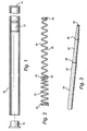
- a fuel rod 10 containing a plurality of nuclear fuel pellets 12 stacked one against the other and against a closed end 14 of the fuel rod.
- a fuel rod plug 16 Prior to closing the opposite end of the fuel rod by welding a fuel rod plug 16 to the fuel rod 10, it is necessary and desirable to axially preload the column of fuel pellets within the fuel rod.
- a locking retainer spring 18 is provided for disposition within the fuel rod and to maintain a pre-selected preload against the stacked fuel pellets 12 within the fuel rod 10.
- Figure 3 illustrates an installation tool 20 for use in installing the locking retainer spring 18 within the fuel rod 10 prior to sealing the pellets 12 within the fuel rod 10 by welding the plug 16 to rod 10.
- the retainer spring 18 includes a plurality of upper coils 22, a transition section 24 and a lower coil section 26.
- the upper spring coil section 22 has a diameter corresponding to the interior diameter of the fuel rod 10 such that an interference fit exists between the upper coiled section 22 and the fuel rod upon installation of the retainer spring 18 into the fuel rod 10.
- the upper coil section 22 includes a pair of closely wound coils 26 at the upper end of the retainer spring 18 and a pair of closely wound coils 28 at the lower end of the upper coiled section 22.
- the latter coils 28 form the transition section 24.
- the transition section 24 separates the larger diameter upper coiled section 22 from the smaller diameter lower coiled section 26.
- the lower coiled section 26 has a natural clearance relative to the inner diameter of the fuel rod.
- the lower coiled section 26 also terminates at its far or lower end in a pair of closely wound coils 30.
- the closely wound coils 30 terminate in a ground flat to provide an interface with the upper most pellet 12 of the column of fuel pellets within the fuel rod 10.
- the retainer spring 18 includes an upper coiled section having an outer diameter corresponding to the interior diameter of the fuel rod 10 and a lower coiled section 26 having a diameter less than and clear of the interior diameter of the fuel rod 10.
- the tool 20 includes a solid preferably metal rod having a first diameter section 40, a smaller diameter section 42 and a transition section 44 between the large and small diameter sections 40 and 42.
- the smaller diameter section 42 opposite transition 44 includes a further transition 46 enabling the rod to taper toward it's distal end 48.
- the larger and smaller diameter sections 40 and 42 respectively are cylindrical.
- the fuel pellets 12 are located within the fuel rod through the open end and butt or stack against one another within the fuel rod.
- the fuel pellets extend within the fuel rod a distance short of the open end of the rod and also short of the plug 16 when applied to close the upper end of the fuel rod. Consequently, it is desirable to maintain the fuel pellets 12 continuously under a pre-selected compressive loading to maintain the pellets in appropriate position within the rods and to prevent movement of the pellets in an axial direction along the rods both when transporting the fuel rods and using the fuel rods in a nuclear reactor.
- the smaller diameter end i.e., the distal end 48 of the tool 20 is inserted into the upper end of the locking retainer spring 18, particularly through the open free end of the larger diameter section 22.
- the transition 44 on the rod 20 will engage the transition 24 on the retainer spring 18. That is, the tool transition 44 seats against the retainer spring transition 24.
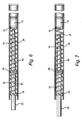
- the combined tool and spring is then inserted into the open end of the fuel rod 10 as illustrated in Figure 4 . Since the diameter of the transition section 24 is the same or substantially the same diameter as the interior diameter of the fuel rod 10, the diameter transition of the spring 18 will start to interfere with the interior diameter of the fuel tube 10.
- a combination of axial force and torque is then applied to the tool 20 to force the combined tool and spring into further penetration within the fuel rod.
- This can be accomplished by a combination of axial force and torque applied to the tool 20.
- the torsion applied to the tool is transmitted to the bottom of the upper coils 22 on the spring adjacent the transition section 24 and acts to reduce the diameter of the upper coils to further facilitate insertion.
- the torque and axial force on the tool is transmitted to the upper coils 22 of the spring such that those forces act to overcome the friction between the upper spring coils 22 and the interior surface to enable the tool and spring to advance into the fuel rod, i.e., into the interior diameter of the fuel rod.
- the balance of the upper coils are then advanced into the fuel rod by the axial force and torsion applied to the tool.
- the combined tool and spring are inserted into the fuel rod until the tip 30 of the lower coiled section 26 of the spring 18 engages against the uppermost fuel pellet 12. At this point, the lower coiled section 26 of the spring 18 is not yet compressed and lies its natural state within the fuel rod 10. (See Figure 5 ).
- the length of the tool 20 is set to give the proper spring deflection to the lower coils and thereby the correct preload is maintained on the fuel column.
- the tool and spring are further advanced until such time that the distal end 48 of tool 20 engages the end of the fuel pellet 12. Once the distal end 48 engages the adjacent fuel pellet 12, the correct preload on the fuel column is obtained because of the dimensional relationships between the length of the tool and the lower coils. Once the tool seats against the fuel pellet, the tool is withdrawn from within the coil spring and the friction between the upper coils 22 and the interior diameter of the fuel rod maintains the axial preload on the fuel column.
- the end 26 of the upper coils of the spring is set back from the end of the fuel rod and is set back likewise from the plug 16 when the plug is welded to the end of the fuel rod. It will be appreciated that there is no necessity to reduce the diameter of the upper coils in this installation process when inserting the spring. Also, the spring can be readily manufactured by standard spring coiling equipment. Further the installation tool is very simple and the installation procedure is easily accomplished manually or by automated equipment.
Landscapes
- Engineering & Computer Science (AREA)
- Physics & Mathematics (AREA)
- Plasma & Fusion (AREA)
- General Engineering & Computer Science (AREA)
- High Energy & Nuclear Physics (AREA)
- Manufacturing & Machinery (AREA)
- Monitoring And Testing Of Nuclear Reactors (AREA)
Claims (4)
- Verfahren zum Einbauen eines Sperrhalters in ein Rohr (10), um innere Komponenten innerhalb des Rohrs (10) unter Druckbelastung zu halten, das die Schritte aufweist:(a) Bereitstellen einer länglichen Haltefeder (18), die Abschnitte mit großem und kleinem Durchmesser aufweist, wobei der Abschnitt mit großem Durchmesser eine Größe für eine Presspassung mit dem Innenumfang des Rohrs (10) aufweist und der Abschnitt mit kleinerem Durchmesser eine Größe mit einem Abstand zu dem Innenumfang des Rohrs aufweist;(b) Einführen eines Abschnitts mit kleinerem Durchmesser eines länglichen Werkzeugs (20) in den Abschnitt mit größerem Durchmesser der länglichen Haltefeder (18), wobei das Werkzeug (20) Abschnitte mit großem (40) und kleinem (42) Durchmesser aufweist;(c) In-Eingriff-Bringen eines Übergangs (44, 46) zwischen den Abschnitten mit kleinerem und größerem Durchmesser (40, 42) des Werkzeugs mit einem Übergang (24) zwischen den Abschnitten mit größerem und kleinerem Durchmesser der länglichen Haltefeder (18);(d) Einführen der Kombination aus dem Werkzeug (40) und der Haltefeder (18) in ein offenes Ende des Rohrs (10), das innere Komponenten enthält, wobei ein Ende des Abschnitts mit kleinerem Durchmesser der Haltefeder (18) zuerst in das Rohr (10) eintritt;(e) Vorwärtsbewegen der Kombination aus dem Werkzeug (40) und der Haltefeder (18) innerhalb des Rohrs, um den Abschnitt mit kleinerem Durchmesser der Haltefeder (18) gegen eine benachbarte innere Komponente zusammenzudrücken, bis ein Ende des Werkzeugs mit der benachbarten inneren Komponente in Eingriff gelangt und der Feder (18) ermöglicht wird, eine ausgewählte axiale Vorspannkraft auf die inneren Komponenten in dem Rohr (10) auszuüben; und(f) Entfernen des Werkzeugs (40) von der Haltefeder (18), während der Abschnitt mit größerem Durchmesser der Haltefeder (18) mit dem Innenumfang des Rohrs (10) in Eingriff gehalten wird, um die axiale Vorspannkraft auf die inneren Komponenten aufrechtzuerhalten.
- Verfahren nach Anspruch 1, das ein Vorwärtsbewegen der Kombination aus dem Werkzeug (40) und der Haltefeder (18) innerhalb des Rohrs (10), um den Federübergang mit dem Innenumfang des Rohrs (10) in Eingriff zu bringen, und anschließendes Verdrehen der Kombination aus dem Werkzeug (40) und der Haltefeder (18) enthält, um den Abschnitt mit größerem Durchmesser der Haltefeder (18) in das Rohr (10) vorwärtszubringen.
- Verfahren nach Anspruch 1 oder Anspruch 2, wobei das Rohr (10) einen Kernbrennstab (10) aufweist.
- Verfahren nach einem beliebigen vorhergehenden Anspruch, wobei die inneren Komponenten Brennstofftabletten (12) aufweisen.
Applications Claiming Priority (1)
| Application Number | Priority Date | Filing Date | Title |
|---|---|---|---|
| US11/329,110 US7290319B2 (en) | 2006-01-11 | 2006-01-11 | Methods for installing a fuel pellet locking retainer in a nuclear fuel rod |
Publications (3)
| Publication Number | Publication Date |
|---|---|
| EP1808864A2 EP1808864A2 (de) | 2007-07-18 |
| EP1808864A3 EP1808864A3 (de) | 2010-03-17 |
| EP1808864B1 true EP1808864B1 (de) | 2012-12-19 |
Family
ID=37719450
Family Applications (1)
| Application Number | Title | Priority Date | Filing Date |
|---|---|---|---|
| EP07100174A Active EP1808864B1 (de) | 2006-01-11 | 2007-01-05 | Verfahren zum Einsetzen eines Brennstofftabletten Sperrhalters in einem Kernbrennstab |
Country Status (4)
| Country | Link |
|---|---|
| US (1) | US7290319B2 (de) |
| EP (1) | EP1808864B1 (de) |
| JP (1) | JP5216221B2 (de) |
| ES (1) | ES2399065T3 (de) |
Families Citing this family (9)
| Publication number | Priority date | Publication date | Assignee | Title |
|---|---|---|---|---|
| US7458156B2 (en) * | 2005-07-06 | 2008-12-02 | Lamb Assembly And Test, Llc | Spool valve assembly apparatus using air vortex insertion |
| KR100889033B1 (ko) * | 2007-08-27 | 2009-03-19 | 한전원자력연료 주식회사 | 핵연료집합체의 항아리형 핵연료봉 내부 공간 증가 스프링 |
| KR101375718B1 (ko) * | 2011-02-21 | 2014-03-20 | 삼성전자주식회사 | 냉매관의 연결구조 및 이를 포함하는 공기조화기 |
| JP2014213256A (ja) * | 2013-04-25 | 2014-11-17 | 株式会社Ihi | 反応管用触媒支持装置 |
| CN103264277B (zh) * | 2013-04-28 | 2015-05-27 | 福斯流体控制(苏州)有限公司 | 弹簧腔装配工装 |
| JP6402373B2 (ja) * | 2014-03-17 | 2018-10-10 | アイセル株式会社 | 装入物固定構造、装入物固定方法、静的混合器および静的混合器の組立方法 |
| CN108039214B (zh) * | 2017-12-12 | 2019-07-19 | 中国科学院近代物理研究所 | 反应堆燃料组件的锁紧与提升机构以及锁紧与提升方法 |
| CN111546073A (zh) * | 2020-05-19 | 2020-08-18 | 绍兴市上虞区舜昌金属制品有限公司 | 一种管件端面加工产线 |
| CN112712907A (zh) * | 2020-12-30 | 2021-04-27 | 中核北方核燃料元件有限公司 | 一种燃料棒压弹簧工装 |
Family Cites Families (21)
| Publication number | Priority date | Publication date | Assignee | Title |
|---|---|---|---|---|
| US2210061A (en) * | 1939-01-24 | 1940-08-06 | Aircraft Screw Prod Co | Inserting tool |
| US2329286A (en) * | 1940-02-24 | 1943-09-14 | Charles A F Meyer | Hose reinforcement inserting apparatus |
| US2300057A (en) * | 1940-03-29 | 1942-10-27 | Charles A F Meyer | Hose reinforcement means |
| US2367945A (en) * | 1941-09-15 | 1945-01-23 | David F Jorgensen | Tool guard |
| US3034869A (en) * | 1958-05-29 | 1962-05-15 | Scient Design Co | Catalyst retainer |
| US3115701A (en) * | 1960-09-01 | 1963-12-31 | Continental Oil Co | Method for installation of sealing rings |
| SE354601B (de) * | 1970-08-19 | 1973-03-19 | C Fredriksson | |
| US3963566A (en) * | 1972-10-06 | 1976-06-15 | General Electric Company | Nuclear fuel column retainer |
| DE8708476U1 (de) * | 1987-06-16 | 1987-08-06 | Klann, Horst, 7730 Villingen-Schwenningen, De | |
| DE3730973A1 (de) * | 1987-09-15 | 1989-03-23 | Reaktor Brennelement Union | Brennstab fuer ein kernreaktor-brennelement |
| US4871509A (en) | 1988-05-02 | 1989-10-03 | General Electric Company | Fuel column retainer using radially compressed spring |
| US5146676A (en) * | 1991-10-30 | 1992-09-15 | Westinghouse Electric Corp. | Hand-actuated spring clip insertion tool |
| US5255298A (en) * | 1992-08-04 | 1993-10-19 | General Electric Company | Locking sleeve plenum spring retainer |
| US5317612A (en) * | 1992-09-25 | 1994-05-31 | Combustion Engineering, Inc. | Use of shape memory alloys in fuel pellet holddown springs |
| US5329566A (en) * | 1993-05-17 | 1994-07-12 | General Electric Company | Plenum spring and getter assembly |
| JP3083258B2 (ja) | 1996-07-02 | 2000-09-04 | 核燃料サイクル開発機構 | 原子炉燃料棒及びそのプレナムスプリング装置 |
| JPH1082877A (ja) * | 1996-09-06 | 1998-03-31 | Nuclear Fuel Ind Ltd | プレナムスプリング |
| FR2790986A1 (fr) * | 1999-03-19 | 2000-09-22 | Michelin & Cie | Procede et dispositif de montage precis d'une jambe de force de suspension mac pherson |
| JP3510211B2 (ja) * | 1999-03-29 | 2004-03-22 | フラマトム アンプ ゲゼルシャフト ミット ベシュレンクテル ハフツング | 加圧水炉の燃料棒用の被覆管およびその被覆管の製造方法 |
| US6182363B1 (en) * | 1999-10-07 | 2001-02-06 | Trw Inc. | Method of making a poppet valve |
| SE0102034L (sv) | 2001-06-08 | 2002-09-10 | Westinghouse Atom Ab | Bränslestav för en nukleär anläggning och plenumfjäder inrättad att anordnas i en bränslestav |
-
2006
- 2006-01-11 US US11/329,110 patent/US7290319B2/en active Active
-
2007
- 2007-01-05 EP EP07100174A patent/EP1808864B1/de active Active
- 2007-01-05 ES ES07100174T patent/ES2399065T3/es active Active
- 2007-01-10 JP JP2007001978A patent/JP5216221B2/ja active Active
Also Published As
| Publication number | Publication date |
|---|---|
| US7290319B2 (en) | 2007-11-06 |
| US20070157452A1 (en) | 2007-07-12 |
| ES2399065T3 (es) | 2013-03-25 |
| JP5216221B2 (ja) | 2013-06-19 |
| JP2007187660A (ja) | 2007-07-26 |
| EP1808864A2 (de) | 2007-07-18 |
| EP1808864A3 (de) | 2010-03-17 |
Similar Documents
| Publication | Publication Date | Title |
|---|---|---|
| EP1808864B1 (de) | Verfahren zum Einsetzen eines Brennstofftabletten Sperrhalters in einem Kernbrennstab | |
| US20200391276A1 (en) | Wire mesh rivet | |
| CN205744760U (zh) | 单面紧固件 | |
| CN101542181B (zh) | 密封塞、密封塞的安装方法及制造密封塞的方法 | |
| US8720302B2 (en) | Anchoring means for the sheath of a bowden cable | |
| US10077567B2 (en) | Method for reinforcing and calibrating a pipe portion | |
| JP2007187660A5 (de) | ||
| JPS63286795A (ja) | 燃料棒の挿入方法及び挿入容易化装置 | |
| DE1514968C3 (de) | Kernreaktor-Brennelement | |
| US4871509A (en) | Fuel column retainer using radially compressed spring | |
| EP1980759B1 (de) | Modulares Anschlusssystem für Betätigungszüge sowie Verfahren und Fügevorrichtung zu dessen Herstellung | |
| CN104204965A (zh) | 用于钟表机芯的发条盒轴、发条盒发条以及包括这种发条和/或这种轴的发条盒 | |
| EP3654502B1 (de) | Verfahren und vorrichtung zum herstellen einer anordnung mit einem genuteten wicklungsträger und einer spulenwicklung für eine elektrische maschine | |
| WO2015096887A1 (de) | Verfahren zum befestigen eines gasgenerators und baugruppe mit einem gasgenerator | |
| US6543817B1 (en) | Process for forming radially upset tube flange and tube connector assembly formed thereby | |
| CN101402347B (zh) | 预张紧器的缸体构造及预张紧器的制造方法 | |
| DE112013003334T5 (de) | Sicherheitsgurt-Aufroller | |
| EP1003988A1 (de) | Kalibrierverfahren | |
| CN105839995B (zh) | 一种锁头及其锁销 | |
| US5069865A (en) | Method of forming a gripper cavity in a fuel rod end plug | |
| EP0361037A2 (de) | Selbstklemmende Sammelraumfeder | |
| DE102017212885A1 (de) | Herstellungsverfahren eines Ventils | |
| US7010078B2 (en) | Fuel rod for a nuclear plant and a plenum spring arranged to be provided in such a fuel rod | |
| DE60021764T2 (de) | Vorrichtung und methode, um den rotor eines hermetisch geschlossenen verdichters zu montieren | |
| EP2276602A1 (de) | Schlauchpaket für schweissvorrichtung |
Legal Events
| Date | Code | Title | Description |
|---|---|---|---|
| PUAI | Public reference made under article 153(3) epc to a published international application that has entered the european phase |
Free format text: ORIGINAL CODE: 0009012 |
|
| AK | Designated contracting states |
Kind code of ref document: A2 Designated state(s): AT BE BG CH CY CZ DE DK EE ES FI FR GB GR HU IE IS IT LI LT LU LV MC NL PL PT RO SE SI SK TR |
|
| AX | Request for extension of the european patent |
Extension state: AL BA HR MK YU |
|
| PUAL | Search report despatched |
Free format text: ORIGINAL CODE: 0009013 |
|
| AK | Designated contracting states |
Kind code of ref document: A3 Designated state(s): AT BE BG CH CY CZ DE DK EE ES FI FR GB GR HU IE IS IT LI LT LU LV MC NL PL PT RO SE SI SK TR |
|
| AX | Request for extension of the european patent |
Extension state: AL BA HR MK RS |
|
| RIC1 | Information provided on ipc code assigned before grant |
Ipc: G21C 3/18 20060101AFI20070216BHEP Ipc: G21C 21/02 20060101ALI20100209BHEP |
|
| 17P | Request for examination filed |
Effective date: 20100917 |
|
| 17Q | First examination report despatched |
Effective date: 20101008 |
|
| AKX | Designation fees paid |
Designated state(s): DE ES SE |
|
| RIC1 | Information provided on ipc code assigned before grant |
Ipc: G21C 21/02 20060101ALI20120521BHEP Ipc: G21C 3/18 20060101AFI20120521BHEP |
|
| GRAP | Despatch of communication of intention to grant a patent |
Free format text: ORIGINAL CODE: EPIDOSNIGR1 |
|
| GRAS | Grant fee paid |
Free format text: ORIGINAL CODE: EPIDOSNIGR3 |
|
| GRAA | (expected) grant |
Free format text: ORIGINAL CODE: 0009210 |
|
| AK | Designated contracting states |
Kind code of ref document: B1 Designated state(s): DE ES SE |
|
| REG | Reference to a national code |
Ref country code: DE Ref legal event code: R082 Ref document number: 602007027420 Country of ref document: DE Representative=s name: RUEGER | ABEL PATENT- UND RECHTSANWAELTE, DE Ref country code: DE Ref legal event code: R082 Ref document number: 602007027420 Country of ref document: DE Representative=s name: RUEGER, BARTHELT & ABEL PATENTANWAELTE, DE Ref country code: DE Ref legal event code: R082 Ref document number: 602007027420 Country of ref document: DE Representative=s name: RUEGER ABEL PATENT- UND RECHTSANWAELTE, DE |
|
| REG | Reference to a national code |
Ref country code: SE Ref legal event code: TRGR |
|
| REG | Reference to a national code |
Ref country code: DE Ref legal event code: R096 Ref document number: 602007027420 Country of ref document: DE Effective date: 20130228 |
|
| REG | Reference to a national code |
Ref country code: ES Ref legal event code: FG2A Ref document number: 2399065 Country of ref document: ES Kind code of ref document: T3 Effective date: 20130325 |
|
| PLBE | No opposition filed within time limit |
Free format text: ORIGINAL CODE: 0009261 |
|
| STAA | Information on the status of an ep patent application or granted ep patent |
Free format text: STATUS: NO OPPOSITION FILED WITHIN TIME LIMIT |
|
| 26N | No opposition filed |
Effective date: 20130920 |
|
| REG | Reference to a national code |
Ref country code: DE Ref legal event code: R097 Ref document number: 602007027420 Country of ref document: DE Effective date: 20130920 |
|
| REG | Reference to a national code |
Ref country code: DE Ref legal event code: R082 Ref document number: 602007027420 Country of ref document: DE Ref country code: DE Ref legal event code: R081 Ref document number: 602007027420 Country of ref document: DE Owner name: GLOBAL NUCLEAR FUEL-AMERICAS, LLC, WILMINGTON, US Free format text: FORMER OWNER: GENERAL ELECTRIC CO., SCHENECTADY, N.Y., US |
|
| PGFP | Annual fee paid to national office [announced via postgrant information from national office to epo] |
Ref country code: SE Payment date: 20231219 Year of fee payment: 18 |
|
| PGFP | Annual fee paid to national office [announced via postgrant information from national office to epo] |
Ref country code: ES Payment date: 20240202 Year of fee payment: 18 |
|
| PGFP | Annual fee paid to national office [announced via postgrant information from national office to epo] |
Ref country code: DE Payment date: 20231219 Year of fee payment: 18 |