EP1808628B1 - Dispositif de serrage pour des conduites - Google Patents
Dispositif de serrage pour des conduites Download PDFInfo
- Publication number
- EP1808628B1 EP1808628B1 EP06123517A EP06123517A EP1808628B1 EP 1808628 B1 EP1808628 B1 EP 1808628B1 EP 06123517 A EP06123517 A EP 06123517A EP 06123517 A EP06123517 A EP 06123517A EP 1808628 B1 EP1808628 B1 EP 1808628B1
- Authority
- EP
- European Patent Office
- Prior art keywords
- clamping device
- bead
- pipe
- main body
- nails
- Prior art date
- Legal status (The legal status is an assumption and is not a legal conclusion. Google has not performed a legal analysis and makes no representation as to the accuracy of the status listed.)
- Active
Links
- 239000011324 bead Substances 0.000 claims abstract description 30
- 239000011505 plaster Substances 0.000 claims abstract description 22
- XLYOFNOQVPJJNP-UHFFFAOYSA-N water Substances O XLYOFNOQVPJJNP-UHFFFAOYSA-N 0.000 claims abstract description 3
- 230000002708 enhancing effect Effects 0.000 claims abstract 2
- 230000007704 transition Effects 0.000 claims description 2
- 238000000034 method Methods 0.000 description 3
- 238000009434 installation Methods 0.000 description 2
- 239000000463 material Substances 0.000 description 2
- 230000001627 detrimental effect Effects 0.000 description 1
- 238000006073 displacement reaction Methods 0.000 description 1
- 230000035515 penetration Effects 0.000 description 1
- 230000003313 weakening effect Effects 0.000 description 1
- 239000002023 wood Substances 0.000 description 1
Images

Classifications
-
- F—MECHANICAL ENGINEERING; LIGHTING; HEATING; WEAPONS; BLASTING
- F16—ENGINEERING ELEMENTS AND UNITS; GENERAL MEASURES FOR PRODUCING AND MAINTAINING EFFECTIVE FUNCTIONING OF MACHINES OR INSTALLATIONS; THERMAL INSULATION IN GENERAL
- F16B—DEVICES FOR FASTENING OR SECURING CONSTRUCTIONAL ELEMENTS OR MACHINE PARTS TOGETHER, e.g. NAILS, BOLTS, CIRCLIPS, CLAMPS, CLIPS OR WEDGES; JOINTS OR JOINTING
- F16B15/00—Nails; Staples
- F16B15/0015—Staples
-
- F—MECHANICAL ENGINEERING; LIGHTING; HEATING; WEAPONS; BLASTING
- F16—ENGINEERING ELEMENTS AND UNITS; GENERAL MEASURES FOR PRODUCING AND MAINTAINING EFFECTIVE FUNCTIONING OF MACHINES OR INSTALLATIONS; THERMAL INSULATION IN GENERAL
- F16L—PIPES; JOINTS OR FITTINGS FOR PIPES; SUPPORTS FOR PIPES, CABLES OR PROTECTIVE TUBING; MEANS FOR THERMAL INSULATION IN GENERAL
- F16L3/00—Supports for pipes, cables or protective tubing, e.g. hangers, holders, clamps, cleats, clips, brackets
- F16L3/02—Supports for pipes, cables or protective tubing, e.g. hangers, holders, clamps, cleats, clips, brackets partly surrounding the pipes, cables or protective tubing
- F16L3/04—Supports for pipes, cables or protective tubing, e.g. hangers, holders, clamps, cleats, clips, brackets partly surrounding the pipes, cables or protective tubing and pressing it against a wall or other support
-
- H—ELECTRICITY
- H02—GENERATION; CONVERSION OR DISTRIBUTION OF ELECTRIC POWER
- H02G—INSTALLATION OF ELECTRIC CABLES OR LINES, OR OF COMBINED OPTICAL AND ELECTRIC CABLES OR LINES
- H02G3/00—Installations of electric cables or lines or protective tubing therefor in or on buildings, equivalent structures or vehicles
- H02G3/30—Installations of cables or lines on walls, floors or ceilings
- H02G3/32—Installations of cables or lines on walls, floors or ceilings using mounting clamps
Definitions
- the present invention relates in general to a clamping device for attaching pipes or tubes, such as for example water pipes, gas pipes or ducts for pulling electrical cables, to a supporting surface, such as plaster boards.
- the clamping device comprises a U-shaped main body having a diameter which corresponds to the diameter of the pipe or tube to be attached.
- the clamping device is configured with attachment means, intended to be pressed into the plaster board in order to secure the pipe or tube to the board, said attachment means coincides with the extension of the legs of the U-shaped main body.
- Said attachment mean are configured to be pressed or driven into the supporting surface, in order to fix the clamping device to the supporting surface.
- clamping device for attaching pipes to walls, wherein the clamping device is given a more or less U-shaped main part and where a straight nail is arranged at the end of each of the leg of the U-shaped main part.
- the nails are intended to be forced into the wall when attaching a pipe by means of the clamping device.
- a disadvantage with such clamping device is that use of straight nails is not suited for obtain a secure attachment on plaster walls, since the plaster material provides very low retaining force for such nails.
- U-shaped clamping device intended to be forced into wood, where the U-shaped head is provided with a single nail on each of the legs of the U-shaped head.
- the nail(s) is intended to be driven into the supporting surface by means of a suitable tool, while the U-shaped head is intended to extend out from the supporting surface, attaching the pipe to said surface.
- Portions of the material forming the U-shaped head is pressed outwards, forming a bead on each side of the clamping device, aligned with the nails and forming a flat portion at the top of the U-shaped head.
- the clamping device comprises a retaining portion intended to cooperate with said installation and an attachment means in the form of two nails intended to be bent sideways away from each other when forced into the supporting surface. Further, the clamping device may preferably be provided with a central nail, arranged between said two nails.
- a clamping device according to the preamble of claim 1 is known from DE 876 341 C .
- An object of the present invention is to provide a clamping device which meets the building requirement in Europe and which also gives the European building operator the possibility of an effective and rational building procedure.
- Another object of the invention is to provide a clamping device which easily may be forced into the supporting structure and which is configured in such way that the clamping device is as rigid as possible, where the bottom of the U-shaped main body will not be deformed during the attachment process, even if the clamping device is hit aslant by a tool.
- a still further object according to the invention is to provide a clamping device, enabling attachment to the rear side of a plaster board, for example boards with a thickness of 13 mm, providing sufficient retaining force for the duct to be attached without affecting the front side of the plaster board, either by penetration or observable deformations.
- a still further object of the invention is to provide a clamping device enabling fixation of the duct prior to attachment of the clamping device to the supporting surface.
- a further important advantage is that the visible front surface of the plaster board, when installed, will not be damaged by the nails of the clamping device.
- a still further advantage is that the pulling duct may be fixed during attachment so that the duct is prevented from displacement with respect to the clamping device subsequent to attachment of the clamping device, and at least prior to attachment of the clamping device to the supporting surface.
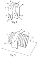
- FIG. 1 shows a perspective view of a preferred embodiment of the clamping device 10 according to the invention.
- the clamping device 10 comprises a U-shaped main body 11 and two attachment means 12, extending out from the legs of the U-shaped main body 11.
- Each attachment means 12 comprises two wing nails 13 and an intermediate, centrally arranged centre nail 14.
- the centre nail 14 is somewhat longer than the two wing nails 13, so that the centre nail 14 engages with the plaster board (not shown) before the two wing nails 13 when the clamping device 10 is positioned around a pipe or tube for attachment of said pipe or tube and before forcing the clamping device 10 into the supporting surface.
- the radius of the U-shaped main body 11 corresponds more or less to the radius of the tube or pipe to be attached to the supporting surface.
- the wing nails 13 may preferably be configured in such way that when the attachment means 12 of the clamping device 10 are driven into the supporting surface, the wing nails 13 are bent sideways out in order to improve the attachment grip of the clamping device 10 in the plaster board.
- the wing nails 13 may for this purpose be configured with a weakening part in the form of a notch, positioned at the root of each wing nail 13.
- the notches may, however be arranged on the opposite side of the foot of each wing nail 13. Further, each wing nail 13 may have such shape that they are forced laterally sideways when forced into the supporting surface.
- the clamping device 10 is provided with an outwards extending, continuous bead or collar 16, extending along the entire curved part of the U-shaped main body 11 and being terminated in the area above the central nail 14.
- the end of the bead or collar 16 and its orientation is such that the bead or collar 16 coincides with an imaginary line from the edge of one central nail 14, along the entire periphery of the U-shaped main body 11 to the edge of the opposite central nail 14.
- bead or the collar 16 The purpose of the bead or the collar 16 is to stiffen the U-shaped part of the clamping device 10, so that said part is not deformed when the clamping device 10 is forced into the supporting surface, and so that the pipe or the tube to be attached to the supporting surface is not damaged during such attachment process.
- FIG 2 shows a preferred embodiment of the invention, wherein the clamping device 10 in general corresponds to the clamping device 10 shown in Figure 1 , the only main difference being that the clamping device 10 according to Figure 2 is provided with inwards projecting bead(s) 20 on each leg of the U-shaped main body 10.
- the purpose of such beads 20 is to reduce the open space between the two legs of the U-shaped main body 11, so that the clamping device 10 more easily may be fixed to the pipe or tube 18, at least prior to attachment to the supporting surface 18.
- the bead 20 may preferably be positioned in the region of the transition between the attachment means 12 and the adjacent part of the legs of the U-shaped main body 11.
- Said bead 20 may consist of one or more bosses or of an elongated body.
- Said one or more bosses or the elongated body may either extend in the longitudinal direction of the legs of the U-shaped main body 11 or in a transverse direction with respect to said legs.
- Said bead 20 may preferably provide additional stiffness to the clamping device 10, so that the clamping device 10 is not deformed during attachment to the supporting surface.
- Figure 3 shows the clamping device 10 used for attachment of a duct 18 for pulling electrical cables (not shown) to a supporting surface 17, for example in the form of a plaster board.
- the bead 16 extends along the entire curved part of the U-shaped main body 11.
- one bead is shown, forming a doubled curved body.
- the clamping device 10 may be provided with several parallel beads 16, for example two beads, extending along the edges of the clamping device 10, or three beads 16. The two ends of the beads may in such latter case coincide with the nails 13,14.
- the bead(s) 16 may have a shape which differs from the doubled curved shape shown in the Figures.
- a safe and secure attachment of pipes or tubes to plaster boards is obtained, providing a large attachment force even in plaster boards, and without producing detrimental damage or leaving un-esthetical appearance to the opposite side of the plaster boards.
- the inwards projecting bead 20 on each leg may consist of two beads, arranged just above each of the two wing nails, or may consist of three beads 20, arranged just above each of the three nails 13,14.
Claims (7)
- Dispositif d'attache (10) conçu pour la fixation d'un tuyau (18), tel qu'une conduite d'eau, une conduite de gaz ou des conduits destinés à tirer des câbles électriques, vers une plaque de plâtre (17) de support, où le dispositif d'attache (10) comprend un corps principal (11) en forme de U dont le diamètre est plus ou moins adapté au diamètre du tuyau (18) et où le dispositif d'attache (10) est doté, à ses deux extrémités libres, d'un moyen de fixation (12) conçu pour être placé en force dans la plaque de plâtre (17) pour une fixation du tuyau (18), chaque moyen de fixation (12) comprenant deux pattes à clouer (13), les deux pattes à clouer (13) étant conçues pour plier dans la direction latérale en s'écartant mutuellement quand le dispositif d'attache (10) est placé en force dans la plaque de plâtre (17), afin d'améliorer la résistance de fixation des moyens de fixation (12) dans la plaque de plâtre (17), et dans lequel le dispositif d'attache (10) est doté, le long de sa partie incurvée (15), d'au moins une nervure ou d'un collier (16) faisant saillie vers l'extérieur, incurvé et continu, qui suit la courbure de la partie incurvée (15) du corps principal (11) en forme de U,
caractérisé en ce que chaque moyen de fixation (12) comprend en outre une pointe centrale (14), située entre les deux pattes à clouer (13), la pointe centrale (14) étant plus longue que les deux pattes à clouer (13) et conçue pour que chacune des extrémités (19) du collier ou de la nervure (16) soit alignée avec les pointes centrales (14). - Dispositif d'attache(10) selon la revendication 1, dans lequel une nervure (20) faisant saillie vers l'intérieur se trouve à la surface interne de la ou des patte(s) du corps principal (11) en forme de U, dans la zone de transition vers le moyen (12) de fixation, cette ou ces nervure(s) limitant la distance entre les deux pattes, ce qui permet de fixer le dispositif d'attache (10) par rapport au tuyau ou à la conduite (18) pendant la phase de fixation.
- Dispositif d'attache (10) selon la revendication 2, dans lequel la ou les nervure(s) (20) faisant saillie vers l'intérieur se trouve(nt) entre la pointe centrale (14) et l'extrémité de la nervure ou du collier (16) au nombre d'au moins un.
- Dispositif d'attache (10) selon la revendication 2 ou 3, dans lequel la nervure (20) est allongée et s'étend dans la direction longitudinale des pattes du corps principal (11) en forme de U.
- Dispositif d'attache (10) selon la revendication 2 ou 3, dans lequel la nervure (20) est allongée et s'étend dans la direction latérale par rapport aux pattes du corps principal (11) en forme de U.
- Dispositif d'attache (10) selon les revendications 2 à 5, dans lequel la nervure est formée par un ou plusieurs bossages alignés, disposés de préférence dans la direction transversale des patte(s) du corps principal (11) en forme de U.
- Dispositif d'attache (10) selon la revendication 6, dans lequel on utilise trois bossages, placés directement au-dessus de chacune des pointes (13, 14).
Applications Claiming Priority (1)
| Application Number | Priority Date | Filing Date | Title |
|---|---|---|---|
| NO20055276A NO325133B1 (no) | 2005-11-09 | 2005-11-09 | Rorklammer |
Publications (3)
| Publication Number | Publication Date |
|---|---|
| EP1808628A2 EP1808628A2 (fr) | 2007-07-18 |
| EP1808628A3 EP1808628A3 (fr) | 2008-03-05 |
| EP1808628B1 true EP1808628B1 (fr) | 2010-01-27 |
Family
ID=35432929
Family Applications (1)
| Application Number | Title | Priority Date | Filing Date |
|---|---|---|---|
| EP06123517A Active EP1808628B1 (fr) | 2005-11-09 | 2006-11-06 | Dispositif de serrage pour des conduites |
Country Status (5)
| Country | Link |
|---|---|
| EP (1) | EP1808628B1 (fr) |
| AT (1) | ATE456760T1 (fr) |
| DE (1) | DE602006012009D1 (fr) |
| DK (1) | DK1808628T3 (fr) |
| NO (1) | NO325133B1 (fr) |
Cited By (2)
| Publication number | Priority date | Publication date | Assignee | Title |
|---|---|---|---|---|
| DE102019118722A1 (de) * | 2019-07-10 | 2021-01-14 | Obo Bettermann Hungary Kft | Einschlagschelle |
| EP4033135A1 (fr) | 2021-01-21 | 2022-07-27 | Pipelife Austria GmbH & Co. KG | Collier de serrage |
Families Citing this family (2)
| Publication number | Priority date | Publication date | Assignee | Title |
|---|---|---|---|---|
| CN102359663A (zh) * | 2011-09-29 | 2012-02-22 | 王兴龙 | 管道安装支架 |
| JP6240925B2 (ja) * | 2014-03-27 | 2017-12-06 | タキロンシーアイ株式会社 | ドレンホース接続構造 |
Family Cites Families (4)
| Publication number | Priority date | Publication date | Assignee | Title |
|---|---|---|---|---|
| BE497499A (fr) * | 1950-02-08 | |||
| DE876341C (de) * | 1951-07-14 | 1953-05-11 | Elfriede Lang | Rohrschelle |
| NO158477C (no) * | 1983-10-12 | 1988-09-14 | Ivan Bach | Anordning ved klammer med slagansats for feste av roer og ledninger. |
| NO306363B1 (no) * | 1998-03-19 | 1999-10-25 | Thor Gunnar Pettersen | Klammer |
-
2005
- 2005-11-09 NO NO20055276A patent/NO325133B1/no unknown
-
2006
- 2006-11-06 EP EP06123517A patent/EP1808628B1/fr active Active
- 2006-11-06 AT AT06123517T patent/ATE456760T1/de active
- 2006-11-06 DE DE602006012009T patent/DE602006012009D1/de active Active
- 2006-11-06 DK DK06123517.2T patent/DK1808628T3/da active
Cited By (3)
| Publication number | Priority date | Publication date | Assignee | Title |
|---|---|---|---|---|
| DE102019118722A1 (de) * | 2019-07-10 | 2021-01-14 | Obo Bettermann Hungary Kft | Einschlagschelle |
| DE102019118722B4 (de) | 2019-07-10 | 2023-06-15 | Obo Bettermann Hungary Kft | Einschlagschelle |
| EP4033135A1 (fr) | 2021-01-21 | 2022-07-27 | Pipelife Austria GmbH & Co. KG | Collier de serrage |
Also Published As
| Publication number | Publication date |
|---|---|
| NO20055276D0 (no) | 2005-11-09 |
| EP1808628A2 (fr) | 2007-07-18 |
| DE602006012009D1 (de) | 2010-03-18 |
| DK1808628T3 (da) | 2010-05-25 |
| ATE456760T1 (de) | 2010-02-15 |
| NO325133B1 (no) | 2008-02-04 |
| EP1808628A3 (fr) | 2008-03-05 |
Similar Documents
| Publication | Publication Date | Title |
|---|---|---|
| US9899817B2 (en) | Mounting brace assembly for mounting an electrical box | |
| CA2834804C (fr) | Dispositif de fixation pour bardage de construction de type feuille | |
| EP1808628B1 (fr) | Dispositif de serrage pour des conduites | |
| US20160298340A1 (en) | Method and A Device to Attach Building Trims | |
| CA2787536C (fr) | Bande avec contrevents souples pour fixation de panneaux de bardage fixes perpendiculairement | |
| US20060101765A1 (en) | Drywall patch for blind hole and picture hanger | |
| US9151058B1 (en) | Ledger board bracket | |
| KR20200142351A (ko) | 마감패널 고정브라켓 및 이를 구비한 외벽마감장치 | |
| JP5809436B2 (ja) | 手摺ブラケット | |
| KR101790993B1 (ko) | 목재 데크 및 판재용 하이브리드 고정 장치 | |
| CN112815278A (zh) | 一种灯槽安装结构及其安装方法 | |
| KR20160061464A (ko) | 천장용 캐링채널 고정장치 | |
| CN202646277U (zh) | 保温钉 | |
| JP4049664B2 (ja) | アウトレットボックス取付金具 | |
| US1793816A (en) | Staple | |
| CN105113755A (zh) | 一种外墙板固定装置 | |
| CN216813224U (zh) | 风管角固件 | |
| CN212897304U (zh) | 一种墙板 | |
| CN219954510U (zh) | 管道限位卡钉 | |
| JP7340651B2 (ja) | 階段用の接続部材 | |
| JP6391227B2 (ja) | 固定用金具およびその使用方法 | |
| WO2008094011A1 (fr) | Dispositif de suspension au plafond | |
| US1787442A (en) | Leader-pipe strap | |
| KR101535563B1 (ko) | 벽체 연결용 고정클립 | |
| JP2007315137A (ja) | 雪止め金具 |
Legal Events
| Date | Code | Title | Description |
|---|---|---|---|
| PUAI | Public reference made under article 153(3) epc to a published international application that has entered the european phase |
Free format text: ORIGINAL CODE: 0009012 |
|
| AK | Designated contracting states |
Kind code of ref document: A2 Designated state(s): AT BE BG CH CY CZ DE DK EE ES FI FR GB GR HU IE IS IT LI LT LU LV MC NL PL PT RO SE SI SK TR |
|
| AX | Request for extension of the european patent |
Extension state: AL BA HR MK YU |
|
| PUAL | Search report despatched |
Free format text: ORIGINAL CODE: 0009013 |
|
| AK | Designated contracting states |
Kind code of ref document: A3 Designated state(s): AT BE BG CH CY CZ DE DK EE ES FI FR GB GR HU IE IS IT LI LT LU LV MC NL PL PT RO SE SI SK TR |
|
| AX | Request for extension of the european patent |
Extension state: AL BA HR MK YU |
|
| 17P | Request for examination filed |
Effective date: 20080827 |
|
| 17Q | First examination report despatched |
Effective date: 20081001 |
|
| AKX | Designation fees paid |
Designated state(s): AT BE BG CH CY CZ DE DK EE ES FI FR GB GR HU IE IS IT LI LT LU LV MC NL PL PT RO SE SI SK TR |
|
| GRAP | Despatch of communication of intention to grant a patent |
Free format text: ORIGINAL CODE: EPIDOSNIGR1 |
|
| GRAS | Grant fee paid |
Free format text: ORIGINAL CODE: EPIDOSNIGR3 |
|
| GRAA | (expected) grant |
Free format text: ORIGINAL CODE: 0009210 |
|
| AK | Designated contracting states |
Kind code of ref document: B1 Designated state(s): AT BE BG CH CY CZ DE DK EE ES FI FR GB GR HU IE IS IT LI LT LU LV MC NL PL PT RO SE SI SK TR |
|
| REG | Reference to a national code |
Ref country code: GB Ref legal event code: FG4D |
|
| REG | Reference to a national code |
Ref country code: CH Ref legal event code: EP |
|
| REG | Reference to a national code |
Ref country code: IE Ref legal event code: FG4D |
|
| REF | Corresponds to: |
Ref document number: 602006012009 Country of ref document: DE Date of ref document: 20100318 Kind code of ref document: P |
|
| REG | Reference to a national code |
Ref country code: NL Ref legal event code: T3 |
|
| REG | Reference to a national code |
Ref country code: SE Ref legal event code: TRGR |
|
| REG | Reference to a national code |
Ref country code: DK Ref legal event code: T3 |
|
| LTIE | Lt: invalidation of european patent or patent extension |
Effective date: 20100127 |
|
| PG25 | Lapsed in a contracting state [announced via postgrant information from national office to epo] |
Ref country code: IS Free format text: LAPSE BECAUSE OF FAILURE TO SUBMIT A TRANSLATION OF THE DESCRIPTION OR TO PAY THE FEE WITHIN THE PRESCRIBED TIME-LIMIT Effective date: 20100527 Ref country code: PT Free format text: LAPSE BECAUSE OF FAILURE TO SUBMIT A TRANSLATION OF THE DESCRIPTION OR TO PAY THE FEE WITHIN THE PRESCRIBED TIME-LIMIT Effective date: 20100527 Ref country code: ES Free format text: LAPSE BECAUSE OF FAILURE TO SUBMIT A TRANSLATION OF THE DESCRIPTION OR TO PAY THE FEE WITHIN THE PRESCRIBED TIME-LIMIT Effective date: 20100508 Ref country code: LT Free format text: LAPSE BECAUSE OF FAILURE TO SUBMIT A TRANSLATION OF THE DESCRIPTION OR TO PAY THE FEE WITHIN THE PRESCRIBED TIME-LIMIT Effective date: 20100127 |
|
| PG25 | Lapsed in a contracting state [announced via postgrant information from national office to epo] |
Ref country code: SI Free format text: LAPSE BECAUSE OF FAILURE TO SUBMIT A TRANSLATION OF THE DESCRIPTION OR TO PAY THE FEE WITHIN THE PRESCRIBED TIME-LIMIT Effective date: 20100127 Ref country code: LV Free format text: LAPSE BECAUSE OF FAILURE TO SUBMIT A TRANSLATION OF THE DESCRIPTION OR TO PAY THE FEE WITHIN THE PRESCRIBED TIME-LIMIT Effective date: 20100127 Ref country code: PL Free format text: LAPSE BECAUSE OF FAILURE TO SUBMIT A TRANSLATION OF THE DESCRIPTION OR TO PAY THE FEE WITHIN THE PRESCRIBED TIME-LIMIT Effective date: 20100127 |
|
| PG25 | Lapsed in a contracting state [announced via postgrant information from national office to epo] |
Ref country code: CY Free format text: LAPSE BECAUSE OF FAILURE TO SUBMIT A TRANSLATION OF THE DESCRIPTION OR TO PAY THE FEE WITHIN THE PRESCRIBED TIME-LIMIT Effective date: 20100127 Ref country code: EE Free format text: LAPSE BECAUSE OF FAILURE TO SUBMIT A TRANSLATION OF THE DESCRIPTION OR TO PAY THE FEE WITHIN THE PRESCRIBED TIME-LIMIT Effective date: 20100127 Ref country code: GR Free format text: LAPSE BECAUSE OF FAILURE TO SUBMIT A TRANSLATION OF THE DESCRIPTION OR TO PAY THE FEE WITHIN THE PRESCRIBED TIME-LIMIT Effective date: 20100428 Ref country code: RO Free format text: LAPSE BECAUSE OF FAILURE TO SUBMIT A TRANSLATION OF THE DESCRIPTION OR TO PAY THE FEE WITHIN THE PRESCRIBED TIME-LIMIT Effective date: 20100127 |
|
| PG25 | Lapsed in a contracting state [announced via postgrant information from national office to epo] |
Ref country code: BG Free format text: LAPSE BECAUSE OF FAILURE TO SUBMIT A TRANSLATION OF THE DESCRIPTION OR TO PAY THE FEE WITHIN THE PRESCRIBED TIME-LIMIT Effective date: 20100427 Ref country code: SK Free format text: LAPSE BECAUSE OF FAILURE TO SUBMIT A TRANSLATION OF THE DESCRIPTION OR TO PAY THE FEE WITHIN THE PRESCRIBED TIME-LIMIT Effective date: 20100127 Ref country code: CZ Free format text: LAPSE BECAUSE OF FAILURE TO SUBMIT A TRANSLATION OF THE DESCRIPTION OR TO PAY THE FEE WITHIN THE PRESCRIBED TIME-LIMIT Effective date: 20100127 |
|
| PLBE | No opposition filed within time limit |
Free format text: ORIGINAL CODE: 0009261 |
|
| STAA | Information on the status of an ep patent application or granted ep patent |
Free format text: STATUS: NO OPPOSITION FILED WITHIN TIME LIMIT |
|
| 26N | No opposition filed |
Effective date: 20101028 |
|
| PG25 | Lapsed in a contracting state [announced via postgrant information from national office to epo] |
Ref country code: IT Free format text: LAPSE BECAUSE OF FAILURE TO SUBMIT A TRANSLATION OF THE DESCRIPTION OR TO PAY THE FEE WITHIN THE PRESCRIBED TIME-LIMIT Effective date: 20100127 |
|
| PG25 | Lapsed in a contracting state [announced via postgrant information from national office to epo] |
Ref country code: MC Free format text: LAPSE BECAUSE OF NON-PAYMENT OF DUE FEES Effective date: 20101130 |
|
| REG | Reference to a national code |
Ref country code: CH Ref legal event code: PL |
|
| GBPC | Gb: european patent ceased through non-payment of renewal fee |
Effective date: 20101106 |
|
| PG25 | Lapsed in a contracting state [announced via postgrant information from national office to epo] |
Ref country code: CH Free format text: LAPSE BECAUSE OF NON-PAYMENT OF DUE FEES Effective date: 20101130 Ref country code: LI Free format text: LAPSE BECAUSE OF NON-PAYMENT OF DUE FEES Effective date: 20101130 |
|
| REG | Reference to a national code |
Ref country code: CH Ref legal event code: AEN Free format text: DAS PATENT IST AUFGRUND DES WEITERBEHANDLUNGSANTRAGS VOM 22.07.2011 REAKTIVIERT WORDEN. Ref country code: CH Ref legal event code: NV Representative=s name: BOVARD AG |
|
| PG25 | Lapsed in a contracting state [announced via postgrant information from national office to epo] |
Ref country code: IE Free format text: LAPSE BECAUSE OF NON-PAYMENT OF DUE FEES Effective date: 20101106 |
|
| PGRI | Patent reinstated in contracting state [announced from national office to epo] |
Ref country code: CH Effective date: 20110722 |
|
| PG25 | Lapsed in a contracting state [announced via postgrant information from national office to epo] |
Ref country code: GB Free format text: LAPSE BECAUSE OF NON-PAYMENT OF DUE FEES Effective date: 20101106 |
|
| PG25 | Lapsed in a contracting state [announced via postgrant information from national office to epo] |
Ref country code: LU Free format text: LAPSE BECAUSE OF NON-PAYMENT OF DUE FEES Effective date: 20101106 Ref country code: HU Free format text: LAPSE BECAUSE OF FAILURE TO SUBMIT A TRANSLATION OF THE DESCRIPTION OR TO PAY THE FEE WITHIN THE PRESCRIBED TIME-LIMIT Effective date: 20100728 |
|
| PG25 | Lapsed in a contracting state [announced via postgrant information from national office to epo] |
Ref country code: TR Free format text: LAPSE BECAUSE OF FAILURE TO SUBMIT A TRANSLATION OF THE DESCRIPTION OR TO PAY THE FEE WITHIN THE PRESCRIBED TIME-LIMIT Effective date: 20100127 |
|
| REG | Reference to a national code |
Ref country code: FR Ref legal event code: PLFP Year of fee payment: 10 |
|
| REG | Reference to a national code |
Ref country code: FR Ref legal event code: PLFP Year of fee payment: 11 |
|
| REG | Reference to a national code |
Ref country code: FR Ref legal event code: PLFP Year of fee payment: 12 |
|
| PGFP | Annual fee paid to national office [announced via postgrant information from national office to epo] |
Ref country code: NL Payment date: 20231020 Year of fee payment: 18 |
|
| PGFP | Annual fee paid to national office [announced via postgrant information from national office to epo] |
Ref country code: SE Payment date: 20231020 Year of fee payment: 18 Ref country code: FR Payment date: 20231019 Year of fee payment: 18 Ref country code: FI Payment date: 20231019 Year of fee payment: 18 Ref country code: DK Payment date: 20231019 Year of fee payment: 18 Ref country code: DE Payment date: 20231019 Year of fee payment: 18 Ref country code: CH Payment date: 20231201 Year of fee payment: 18 Ref country code: AT Payment date: 20231023 Year of fee payment: 18 |
|
| PGFP | Annual fee paid to national office [announced via postgrant information from national office to epo] |
Ref country code: BE Payment date: 20231019 Year of fee payment: 18 |