EP1808584A1 - Verfahren und Vorrichtung zum Entfernen eines Körpers aus einem Gehäuse - Google Patents
Verfahren und Vorrichtung zum Entfernen eines Körpers aus einem Gehäuse Download PDFInfo
- Publication number
- EP1808584A1 EP1808584A1 EP20060127197 EP06127197A EP1808584A1 EP 1808584 A1 EP1808584 A1 EP 1808584A1 EP 20060127197 EP20060127197 EP 20060127197 EP 06127197 A EP06127197 A EP 06127197A EP 1808584 A1 EP1808584 A1 EP 1808584A1
- Authority
- EP
- European Patent Office
- Prior art keywords
- jacket
- cutting
- cut
- housing
- treatment body
- Prior art date
- Legal status (The legal status is an assumption and is not a legal conclusion. Google has not performed a legal analysis and makes no representation as to the accuracy of the status listed.)
- Granted
Links
Images




Classifications
-
- C—CHEMISTRY; METALLURGY
- C22—METALLURGY; FERROUS OR NON-FERROUS ALLOYS; TREATMENT OF ALLOYS OR NON-FERROUS METALS
- C22B—PRODUCTION AND REFINING OF METALS; PRETREATMENT OF RAW MATERIALS
- C22B7/00—Working up raw materials other than ores, e.g. scrap, to produce non-ferrous metals and compounds thereof; Methods of a general interest or applied to the winning of more than two metals
- C22B7/005—Separation by a physical processing technique only, e.g. by mechanical breaking
-
- B—PERFORMING OPERATIONS; TRANSPORTING
- B23—MACHINE TOOLS; METAL-WORKING NOT OTHERWISE PROVIDED FOR
- B23D—PLANING; SLOTTING; SHEARING; BROACHING; SAWING; FILING; SCRAPING; LIKE OPERATIONS FOR WORKING METAL BY REMOVING MATERIAL, NOT OTHERWISE PROVIDED FOR
- B23D21/00—Machines or devices for shearing or cutting tubes
-
- B—PERFORMING OPERATIONS; TRANSPORTING
- B23—MACHINE TOOLS; METAL-WORKING NOT OTHERWISE PROVIDED FOR
- B23D—PLANING; SLOTTING; SHEARING; BROACHING; SAWING; FILING; SCRAPING; LIKE OPERATIONS FOR WORKING METAL BY REMOVING MATERIAL, NOT OTHERWISE PROVIDED FOR
- B23D21/00—Machines or devices for shearing or cutting tubes
- B23D21/02—Machines or devices for shearing or cutting tubes otherwise than in a plane perpendicular to the axis of the tube, e.g. for making mitred cuts, for making bicycle frames
-
- C—CHEMISTRY; METALLURGY
- C22—METALLURGY; FERROUS OR NON-FERROUS ALLOYS; TREATMENT OF ALLOYS OR NON-FERROUS METALS
- C22B—PRODUCTION AND REFINING OF METALS; PRETREATMENT OF RAW MATERIALS
- C22B11/00—Obtaining noble metals
- C22B11/02—Obtaining noble metals by dry processes
- C22B11/021—Recovery of noble metals from waste materials
-
- F—MECHANICAL ENGINEERING; LIGHTING; HEATING; WEAPONS; BLASTING
- F01—MACHINES OR ENGINES IN GENERAL; ENGINE PLANTS IN GENERAL; STEAM ENGINES
- F01N—GAS-FLOW SILENCERS OR EXHAUST APPARATUS FOR MACHINES OR ENGINES IN GENERAL; GAS-FLOW SILENCERS OR EXHAUST APPARATUS FOR INTERNAL-COMBUSTION ENGINES
- F01N2330/00—Structure of catalyst support or particle filter
- F01N2330/06—Ceramic, e.g. monoliths
-
- F—MECHANICAL ENGINEERING; LIGHTING; HEATING; WEAPONS; BLASTING
- F01—MACHINES OR ENGINES IN GENERAL; ENGINE PLANTS IN GENERAL; STEAM ENGINES
- F01N—GAS-FLOW SILENCERS OR EXHAUST APPARATUS FOR MACHINES OR ENGINES IN GENERAL; GAS-FLOW SILENCERS OR EXHAUST APPARATUS FOR INTERNAL-COMBUSTION ENGINES
- F01N2450/00—Methods or apparatus for fitting, inserting or repairing different elements
-
- F—MECHANICAL ENGINEERING; LIGHTING; HEATING; WEAPONS; BLASTING
- F01—MACHINES OR ENGINES IN GENERAL; ENGINE PLANTS IN GENERAL; STEAM ENGINES
- F01N—GAS-FLOW SILENCERS OR EXHAUST APPARATUS FOR MACHINES OR ENGINES IN GENERAL; GAS-FLOW SILENCERS OR EXHAUST APPARATUS FOR INTERNAL-COMBUSTION ENGINES
- F01N2450/00—Methods or apparatus for fitting, inserting or repairing different elements
- F01N2450/20—Methods or apparatus for fitting, inserting or repairing different elements by mechanical joints, e.g. by deforming housing, tube, baffle plate or parts thereof
-
- Y—GENERAL TAGGING OF NEW TECHNOLOGICAL DEVELOPMENTS; GENERAL TAGGING OF CROSS-SECTIONAL TECHNOLOGIES SPANNING OVER SEVERAL SECTIONS OF THE IPC; TECHNICAL SUBJECTS COVERED BY FORMER USPC CROSS-REFERENCE ART COLLECTIONS [XRACs] AND DIGESTS
- Y02—TECHNOLOGIES OR APPLICATIONS FOR MITIGATION OR ADAPTATION AGAINST CLIMATE CHANGE
- Y02P—CLIMATE CHANGE MITIGATION TECHNOLOGIES IN THE PRODUCTION OR PROCESSING OF GOODS
- Y02P10/00—Technologies related to metal processing
- Y02P10/20—Recycling
Definitions
- the present invention relates to a method for removing at least one exhaust treatment body from a housing.
- the invention also relates to a device for free cutting at least one exhaust treatment body arranged in a housing.
- Exhaust gas treatment devices such as catalysts and particle filters, have in a housing, which is usually made of sheet steel, one or more exhaust treatment body, which are configured for example of a ceramic material and preferably as a monolith.
- the respective exhaust treatment body is axially fixed in a jacket of the housing, preferably by means of a bearing mat, which encloses the respective exhaust treatment body in the circumferential direction and which is pressed radially between the exhaust treatment body and the jacket.
- the housing may be provided at axial ends of the shell with end portions, for example form a funnel-shaped inlet and a funnel-shaped outlet for the exhaust gas flow.
- the at least one exhaust treatment body may be necessary to remove the at least one exhaust treatment body from the housing, for example for material separation during recycling or when reuse of the extracted exhaust treatment body is intended.
- the latter is the case in particular if faults occur on the housing side during the production of the exhaust gas treatment device, which errors call into question the usability of the exhaust gas treatment device.
- the exhaust treatment bodies regularly represent the most expensive components of the exhaust gas treatment devices, there is a certain interest in removing them from the housing in such a way that they can then be used as directly as possible again in another housing. For this purpose, it is necessary to remove the respective exhaust treatment body from the housing so that it is neither damaged nor polluted.
- the present invention addresses the problem of providing an advantageous way of removing at least one exhaust treatment body from a housing, which is characterized in particular by a reduced risk of contamination and damage to the respective exhaust treatment body.
- the invention is based on the general idea of cutting the casing of the housing from one axial jacket end to the other axial jacket end mechanically and without cutting.
- the respective exhaust treatment body can then be removed from the cut-up jacket.
- the non-cutting and mechanical cutting is characterized by the fact that there are no impurities that could be deposited on the respective exhaust treatment body. In particular, no chips occur, as they occur, for example, when sawing or milling, and also no sparks, as they occur, for example, when separating welding of the cutting loops. Neither does mechanical dust cause dust formation. Since no contamination occurs during mechanical cutting, the risk of contamination or damage to the exhaust treatment body is also reduced.
- the respective exhaust treatment body can usually be removed from the cut-up jacket in such a way that no large forces have to be introduced onto the respective exhaust-gas treatment body. Accordingly, in this regard, the risk of damage can be reduced, which is particularly important if the exhaust treatment body made of a brittle material, such as ceramics, especially cordierite.
- a device 1 according to the invention which serves for free cutting at least one exhaust treatment body 2, which is arranged in a housing 3 of an unspecified exhaust gas treatment device, comprises at least one slicing station 4.
- the device 1 also comprises a cutting station 5.
- the exhaust gas treatment device may be, for example, a catalytic converter or a particulate filter.
- the at least one exhaust treatment body 2 is preferably a catalyst body or a particle filter body.
- a single exhaust treatment body 2 is arranged in the housing 3 here.
- a plurality of exhaust treatment body 2 may be arranged in the housing 3.
- the exhaust treatment body 2 may for example consist of a ceramic material.
- the exhaust treatment body 2 is a monolith.
- the exhaust treatment body 2 can be assembled from a plurality of monolithic partial bodies.
- the housing 3 has a jacket 6, which surrounds the exhaust treatment body 2 in the circumferential direction. Furthermore, the housing 3 preferably has two axial end sections 7 and 8, which are arranged at the axial ends of the jacket 6. In particular, the end sections 7, 8 are welded to the casing 6 or formed thereon by deformation. Basically, the present invention is also applicable to a housing 3, which is made in the so-called half shell construction, in which the shell 6 is assembled from two half-shells , In the present case, the end sections 7, 8 are designed as funnels; as well as other embodiments are possible. Usually owns the jacket 6 and thus also the exhaust treatment body 2 a circular or elliptical cross section; as well as other cross sections are possible. Sheath 6 and end sections 7, 8 are usually made of metal, usually steel sheet, preferably stainless steel sheet.
- the exhaust treatment body 2 is preferably enveloped in the interior of the shell 6 by a bearing material 9 in the circumferential direction.
- the bearing material 9 is for example in the form of a bearing mat single-layer or multi-layer wrapped around the exhaust treatment body 2 and used with this in the jacket 6.
- the bearing material 9 is arranged radially between the jacket 6 and the exhaust treatment body 2 and radially compressed. As a result, a tension is achieved, which axially fixes the exhaust treatment body 2 in the jacket 6 and also protects against direct contact with the jacket 6.
- the slicing station 4 and the cutting station 5 each have a holding device 10, by means of which the housing 3 can be fixed.
- both stations 4, 5 are assigned a common holding device 10.
- each station 4, 5 have its own holding device 10, whereby the cycle times for cutting free of the exhaust treatment body 2 are reduced and whereby the separate holding devices 10 can be better adapted to their respective task.
- the slicing station 4 also has at least one slicing tool 11, by means of which the casing 6 can be cut without cutting and mechanically.
- the slicing tool 11 is preferably equipped with a blade 12, the cutting edge of which is denoted by 13 here. It is clear that in another embodiment, two or more such slicing tools 11 may be present.
- the slicing station 4 is designed such that it allows an axial relative adjustment between the holding device 10 and the slicing tool 11, which is indicated in FIGS. 3 and 4 by an arrow 14.
- the slicing tool 11 can be moved relative to the stationary holding device 10;
- a stationary slicing tool 11 is conceivable.
- the cutting station 5 has at least one cutting tool 15 with the aid of which the end sections 7, 8 can be cut off from the casing 6 or from the housing 3 without cutting and mechanically.
- the cutting tool 15 is preferably equipped with a rolling blade 16, the cutting edge is denoted by 17.
- the rolling knife 16 is mounted rotatably about a roll axis 18 on the cutting tool 15. It is clear that in another embodiment, two or more such cutting tools 15 may be provided.
- the cutting station 5 is preferably designed such that it is between the holding device 10 and the cutting tool 15 allows a oriented in the circumferential direction of the housing 3 and the shell 6 relative adjustment. This relative adjustment is achieved in the example shown in that the holding device 10 can rotate the housing 3 thus held about an axis of rotation 19, which is indicated in FIGS. 1 and 2 by an arrow 20, while the cutting tool 15 is stationary. Likewise, a rotating cutting tool 15 is conceivable.
- the device 1 or the method according to the invention operates as follows:
- the housing 3 is inserted into the holding device 10 and held therein.
- the cutting tool 15 is positioned to cut off the freestanding first end portion 7.
- the roller blade 16 touches the jacket 6 radially with its cutting edge 17 and is oriented so that its roll axis 18 extends parallel to the axis of rotation 19 of the holding device 10.
- the holding device 10 then rotates the housing 3 about the axis of rotation 19.
- the rolling blade 16 is pressed radially according to an arrow 21 to the jacket 6.
- the rolling blade 16 rolls on the outside of the housing 3 or on the outside of the jacket 6.
- the roller blade 16 Due to the contact pressure 21, the roller blade 16 increasingly cuts into the housing 3 or into the casing 6 until the casing 6 is severed, as a result of which the roller cutter 16 cuts off the first end section 7 from the casing 6.
- the cutting station 5 can cut off the respective end section 7 or 8 without cutting from the jacket 6. Other contaminants, such as sparks or dust, do not occur regularly during this cutting process.
- the second end section 8 is cut off from the housing 3 or from the jacket 6.
- the remaining housing 3 is first removed from the holding device 10, turned and fixed again therein.
- the cutting tool 15 is positioned to cut off the second end portion 18 on the remaining housing 3 or on the jacket 6.
- the chipless cutting process is then identical to the cutting of the first end section 7.
- the slicing tool 11 is positioned relative to the holding device 10 such that the blade 12 is located with its cutting edge 13 axially adjacent to a first axial jacket end 23.
- the blade 12 extends with its preferably employed cutting edge 13 in the radial direction to the extent that it penetrates the jacket 6 in any case and can cut into the bearing material 9 and does not touch the exhaust treatment body 2.
- the holding device 10 is designed so that the slicing tool 11 perform the blade 12 at least on one side at least over the entire axial extent of the shell 6 through the jacket 6 can.
- the jacket 6 is thereby cut from the first axial jacket end 23 to the other or second axial jacket end 24, without cutting and mechanically.
- the relative adjustment 14 of the slicing tool 11 takes place axially and thus parallel to the axis of rotation 19. This results in a straight-line section, which is designated by 25 in FIG.
- the sheath 6 is continuously cut from the first sheath end 23 to the second sheath end 24, whereby the said cut 25 is formed.
- the slicing tool 11 By returning the slicing tool 11 to the position shown in Fig. 3 and rotating the jacket 6, e.g. 180 ° about the axis of rotation 19 can be made in a corresponding manner to the already prepared first section 25, a second section, which is designated in Fig. 8 with 26. It is also possible to produce the two cuts 25, 26 with two cutting tools 11 simultaneously. Also, the cutting of the shell 6 is carried out without cutting and mechanically, whereby contamination and damage to the exhaust treatment body 2 can be avoided.
- Fig. 5 shows the housing 3 after the cutting of the end portions 7, 8 and before the cutting of the jacket 6. This corresponds to the state shown in Fig. 3.
- the bearing material 9 enclosing the exhaust treatment body 2 in the circumferential direction is designed here as a single-layer bearing mat, the ends of which abut one another at 27.
- the bearing material 9 is radially biased so that it is not readily possible to push out the exhaust treatment body 2 without risk of damage in the axial direction of the jacket 6. Accordingly, in the invention, the jacket 6 is cut open in the axial direction.
- Fig. 6 shows the state of the housing 3 after the introduction of the first section 25 in the shell 6. Obviously, this section 25 extends in the radial direction through the jacket 6 completely through and extends into the bearing material 9 inside. In any case, a radial distance to the exhaust treatment body 2 is maintained.
- a single cut 25 may be sufficient to cut the exhaust treatment body 2 from the housing 3 and the shell 6, respectively.
- the cut-up jacket 6 can then be bent up before the exhaust treatment body 2 is removed. This increases an unspecified distance between lateral edges 28, which extend along the section 25.
- the exhaust treatment body 2, together with the bearing material 9, can be removed from the remaining housing 3 or the jacket 6. The bearing material 9 can then be removed easily from the exhaust treatment body 2.
- the jacket 6 can accordingly Fig. 8 as mentioned above are cut open at least on two sides, whereby at least the two cuts 25, 26 are formed, which are preferably diametrically opposed.
- the at least two cuts 25, 26 of the shell 6 is divided into two or more shell segments 29, 30.
- the two cut-out jacket segments or jacket halves 29, 30 can be removed from the exhaust treatment body 2, as shown in FIG.
- the exhaust treatment body 2 is removed from the housing 3 and the jacket 6.
Landscapes
- Engineering & Computer Science (AREA)
- Mechanical Engineering (AREA)
- Chemical & Material Sciences (AREA)
- Organic Chemistry (AREA)
- Materials Engineering (AREA)
- Metallurgy (AREA)
- Manufacturing & Machinery (AREA)
- Life Sciences & Earth Sciences (AREA)
- Environmental & Geological Engineering (AREA)
- General Life Sciences & Earth Sciences (AREA)
- Geology (AREA)
- Exhaust Gas After Treatment (AREA)
- Control And Other Processes For Unpacking Of Materials (AREA)
- Automatic Assembly (AREA)
- Turning (AREA)
Abstract
Description
- Die vorliegende Erfindung betrifft ein Verfahren zum Entnehmen wenigstens eines Abgasbehandlungskörpers aus einem Gehäuse. Die Erfindung betrifft außerdem eine Vorrichtung zum Freischneiden wenigstens eines in einem Gehäuse angeordneten Abgasbehandlungskörpers.
- Abgasbehandlungseinrichtungen, die wie z.B. Katalysatoren und Partikelfilter, weisen in einem Gehäuse, das in der Regel aus Stahlblech hergestellt ist, einen oder mehrere Abgasbehandlungskörper auf, die beispielsweise aus einem keramischen Werkstoff und vorzugsweise als Monolith ausgestaltet sind. Üblicherweise ist der jeweilige Abgasbehandlungskörper in einem Mantel des Gehäuses axial fixiert, vorzugsweise mit Hilfe einer Lagermatte, die den jeweiligen Abgasbehandlungskörper in Umfangsrichtung umhüllt und die radial zwischen dem Abgasbehandlungskörper und dem Mantel verpresst ist. Durch diese Verpressung des Lagermaterials entsteht eine starke axiale Fixierung für den jeweiligen Abgasbehandlungskörper im Mantel. Zusätzlich kann das Gehäuse an axialen Enden des Mantels mit Endabschnitten versehen sein, die beispielsweise einen trichterförmigen Einlauf und einen trichterförmigen Auslauf für die Abgasströmung bilden.
- Aus unterschiedlichen Gründen kann es erforderlich sein, den wenigstens einen Abgasbehandlungskörper aus dem Gehäuse zu entnehmen, beispielsweise zur Werkstofftrennung beim Recycling oder wenn eine Wiederverwendungen der entnommen Abgasbehandlungskörper beabsichtigt ist. Letzteres ist insbesondere dann der Fall, wenn während der Herstellung der Abgasbehandlungseinrichtung gehäuseseitig Fehler auftreten, welchen die Verwendbarkeit der Abgasbehandlungseinrichtung in Frage stellen. Da die Abgasbehandlungskörper regelmäßig die teuersten Komponenten der Abgasbehandlungseinrichtungen darstellen, besteht ein gewisses Interesse daran, diese so aus dem Gehäuse herauszunehmen, dass sie anschließend möglichst unmittelbar wieder in ein anderes Gehäuse eingesetzt werden können. Hierzu ist es erforderlich, den jeweiligen Abgasbehandlungskörper so aus dem Gehäuse zu entnehmen, dass er dabei weder beschädigt noch verschmutzt wird.
- Die vorliegende Erfindung beschäftigt sich mit dem Problem, einen vorteilhaften Weg zum Entfernen wenigstens eines Abgasbehandlungskörpers aus einem Gehäuse aufzuzeigen, der sich insbesondere durch eine reduzierte Verschmutzungs- und Beschädigungsgefahr für den jeweiligen Abgasbehandlungskörper auszeichnet.
- Dieses Problem wird erfindungsgemäß durch die Gegenstände der unabhängigen Ansprüche gelöst. Vorteilhafte Ausführungsformen sind Gegenstand der abhängigen Ansprüche.
- Die Erfindung beruht auf dem allgemeinen Gedanken, den Mantel des Gehäuses von einem axialen Mantelende zum anderen axialen Mantelende mechanisch und spanlos aufzuschneiden. Aus dem aufgeschnittenen Mantel kann dann der jeweilige Abgasbehandlungskörper entnommen werden. Das spanlose und mechanischen Aufschneiden zeichnet sich dadurch aus, dass dabei keine Verunreinigungen entstehen, die sich am jeweiligen Abgasbehandlungskörper ablagern könnten. Insbesondere entstehen keine Späne, wie sie z.B. beim Sägen oder Fräsen auftreten, und auch keine Funken, wie sie z.B. beim Trennschweißen der Trennschleifen auftreten. Ebenso wenig kommt es beim mechanischen Schneiden zu einer Staubentwicklung. Da somit beim mechanischen Schneiden keine Verunreinigungen entstehen, ist auch die Gefahr einer Verschmutzung oder Beschädigung der Abgasbehandlungskörper reduziert. Desweiteren lässt sich der jeweilige Abgasbehandlungskörper aus dem aufgeschnittenen Mantel in der Regel so herausnehmen, dass dabei keine großen Kräfte auf den jeweiligen Abgasbehandlungskörper eingeleitet werden müssen. Dementsprechend kann auch diesbezüglich die Beschädigungsgefahr reduziert werden, was insbesondere dann von Bedeutung ist, wenn die Abgasbehandlungskörper aus einem spröden Material bestehen, wie z.B. Keramik, insbesondere Cordierit.
- Weitere wichtige Merkmale und Vorteile der Erfindung ergeben sich aus den Unteransprüchen, aus den Zeichnungen und aus der zugehörigen Figurenbeschreibung anhand der Zeichnungen.
- Es versteht sich, dass die vorstehend genannten und die nachstehend noch zu erläuternden Merkmale nicht nur in der jeweils angegebenen Kombination, sondern auch in anderen Kombinationen oder in Alleinstellung verwendbar sind, ohne den Rahmen der vorliegenden Erfindung zu verlassen.
- Bevorzugte Ausführungsbeispiele der Erfindung sind in den Zeichnungen dargestellt und werden in der nachfolgenden Beschreibung näher erläutert, wobei sich gleiche Bezugszeichen auf gleiche oder ähnliche oder funktional gleiche Bauteile beziehen.
- Es zeigen, jeweils schematisch,
- Fig. 1
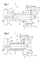
- eine stark vereinfachte, prinzipielle Ansicht einer Vorrichtung zum Freischneiden eines Abgasbehandlungskörpers beim Abschneiden eines ersten Endabschnitts des Gehäuses,
- Fig. 2
- eine Ansicht wie in Fig. 1, jedoch beim Abschneiden eines zweiten Endabschnitts des Gehäuses,
- Fig. 3
- eine Ansicht wie in Fig. 2, jedoch vor dem Aufschneiden eines Mantels des Gehäuses,
- Fig. 4
- eine Ansicht wie in Fig. 3, jedoch nach dem Aufschneiden des Mantels,
- Fig. 5
- einen vereinfachten Querschnitt durch das Gehäuse im Bereich des Mantels vor dem Aufschneiden des Mantels entsprechend Schnittlinien V in Fig. 1,
- Fig. 6
- ein Querschnitt wie in Fig. 5, jedoch nach dem Aufschneiden des Mantels entsprechend Schnittlinien VI in Fig. 4,
- Fig. 7
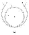
- ein Querschnitt wie in Fig. 6, jedoch nach dem Aufbiegen des Mantels,
- Fig. 8
- ein Querschnitt wie in Fig. 6, jedoch bei einer Ausführungsform mit zwei gegenüberliegenden Schnitten,
- Fig. 9
- eine Ansicht wie in Fig. 8, jedoch beim Entfernen freigeschnittener Gehäusehälften.
- Entsprechend den Fig. 1 bis 4 umfasst eine erfindungsgemäße Vorrichtung 1, die zum Freischneiden wenigstens eines Abgasbehandlungskörpers 2 dient, der in einem Gehäuse 3 einer nicht näher bezeichneten Abgasbehandlungseinrichtung angeordnet ist, zumindest eine Aufschneidstation 4. In der dargestellten bevorzugten Ausführungsform umfasst die Vorrichtung 1 außerdem eine Abschneidstation 5.
- Bei der Abgasbehandlungseinrichtung kann es beispielsweise um einen Katalysator oder um ein Partikelfilter handeln. Dementsprechend handelt es sich bei dem wenigstens einen Abgasbehandlungskörper 2 vorzugsweise um einen Katalysatorkörper oder um einen Partikelfilterkörper. Zur vereinfachten Darstellung ist im Gehäuse 3 hier nur ein einziger Abgasbehandlungskörper 2 angeordnet. Es ist klar, dass bei anderen Ausführungsformen auch mehrere Abgasbehandlungskörper 2 im Gehäuse 3 angeordnet sein können. Der Abgasbehandlungskörper 2 kann beispielsweise aus einem keramischen Material bestehen. Insbesondere handelt es sich beim Abgasbehandlungskörper 2 um einen Monolithen. Ebenso kann der Abgasbehandlungskörper 2 aus mehreren monolithischen Teilkörpern zusammengebaut sein.
- Das Gehäuse 3 weist einen Mantel 6 auf, der den Abgasbehandlungskörper 2 in Umfangsrichtung umschließt. Desweiteren weist das Gehäuse 3 vorzugsweise zwei axiale Endabschnitte 7 und 8 auf, die an den axialen Enden des Mantels 6 angeordnet sind. Insbesondere sind die Endabschnitte 7, 8 an den Mantel 6 angeschweißt oder daran durch Umformung ausgebildet. Das Gehäuse 3 ist hier in der sogenannten Rohrbauweise gefertigt und besitzt demnach einen einstückigen, rohrförmigen Mantel 6. Grundsätzlich ist die vorliegende Erfindung auch bei einem Gehäuse 3 anwendbar, das in der sogenannten Halbschalenbauweise gefertigt ist, bei welcher der Mantel 6 aus zwei Halbschalen zusammengebaut ist. Im vorliegenden Fall sind die Endabschnitte 7, 8 als Trichter ausgestaltet; ebenso sind andere Ausführungsformen möglich. Üblicherweise besitzt der Mantel 6 und somit auch der Abgasbehandlungskörper 2 einen kreisförmigen oder elliptischen Querschnitt; ebenso sind andere Querschnitte möglich. Mantel 6 und Endabschnitte 7, 8 bestehen üblicherweise aus Metall, in der Regel Stahlblech, vorzugsweise Edelstahlblech.
- Der Abgasbehandlungskörper 2 ist im Inneren des Mantels 6 vorzugsweise von einem Lagermaterial 9 in Umfangsrichtung umhüllt. Das Lagermaterial 9 ist beispielsweise in Form einer Lagermatte einlagig oder mehrlagig um den Abgasbehandlungskörper 2 gewickelt und mit diesem in den Mantel 6 eingesetzt. Im fertig montierten Zustand ist das Lagermaterial 9 radial zwischen dem Mantel 6 und dem Abgasbehandlungskörper 2 angeordnet und radial verpresst. Hierdurch wird eine Verspannung erzielt, die den Abgasbehandlungskörper 2 im Mantel 6 axial fixiert und außerdem vor einem unmittelbaren Kontakt mit dem Mantel 6 schützt.
- Die Aufschneidstation 4 und die Abschneidstation 5 weisen jeweils eine Halteeinrichtung 10 auf, mit deren Hilfe das Gehäuse 3 fixierbar ist. Im gezeigten Ausführungsbeispiel ist beiden Stationen 4, 5 eine gemeinsame Halteinrichtung 10 zugeordnet. Bei einer anderen Ausführungsform kann jede Station 4, 5 eine eigene Halteeinrichtung 10 aufweisen, wodurch die Taktzeiten zum Freischneiden des Abgasbehandlungskörpers 2 verkleinert werden und wodurch die separaten Halteeinrichtungen 10 besser an ihre jeweilige Aufgabe angepasst werden können.
- Die Aufschneidstation 4 weist außerdem zumindest ein Aufschneidwerkzeug 11 auf, mit dessen Hilfe der Mantel 6 spanlos und mechanisch aufgeschnitten werden kann. Hierzu ist das Aufschneidwerkzeug 11 vorzugsweise mit einer Klinge 12 ausgestattet, deren Schneide hier mit 13 bezeichnet ist. Es ist klar, dass bei einer anderen Ausführungsform auch zwei oder mehr derartige Aufschneidwerkzeuge 11 vorhanden sein können.
- Die Aufschneidstation 4 ist so ausgestaltet, dass sie zwischen der Halteeinrichtung 10 und dem Aufschneidwerkzeug 11 eine axiale Relativverstellung ermöglicht, die in den Fig. 3 und 4 durch einen Pfeil 14 angedeutet ist. Im Beispiel ist das Aufschneidwerkzeug 11 relativ zur stationären Halteeinrichtung 10 verfahrbar; ebenso ist ein stationäres Aufschneidwerkzeug 11 denkbar.
- Die Abschneidstation 5 weist wenigstens ein Abschneidwerkzeug 15, mit dessen Hilfe die Endabschnitte 7, 8 vom Mantel 6 bzw. vom Gehäuse 3 spanlos und mechanisch abschneidbar sind. Hierzu ist das Abschneidwerkzeug 15 vorzugsweise mit einem Rollmesser 16 ausgestattet, dessen Schneide mit 17 bezeichnet ist. Das Rollmesser 16 ist um eine Rollachse 18 drehbar am Abschneidwerkzeug 15 gelagert. Es ist klar, dass bei einer anderen Ausführungsform auch zwei oder mehr derartiger Abschneidwerkzeuge 15 vorgesehen sein können.
- Die Abschneidstation 5 ist vorzugsweise so ausgestaltet, dass sie zwischen der Halteinrichtung 10 und dem Abschneidwerkzeug 15 eine in der Umfangsrichtung des Gehäuses 3 bzw. des Mantels 6 orientierte Relativverstellung ermöglicht. Diese Relativverstellung wird im gezeigten Beispiel dadurch erreicht, dass die Halteeinrichtung 10 das damit festgehaltene Gehäuse 3 um eine Drehachse 19 drehen kann, was in den Fig. 1 und 2 durch einen Pfeil 20 angedeutet ist, während das Abschneidwerkzeug 15 stationär ist. Ebenso ist ein rotierendes Abschneidwerkzeug 15 denkbar.
- Die erfindungsgemäße Vorrichtung 1 bzw. das erfindungsgemäße Verfahren arbeitet wie folgt:
- Entsprechend Fig. 1 wird das Gehäuse 3 in die Halteeinrichtung 10 eingesetzt und darin festgehalten. Das Abschneidwerkzeug 15 wird zum Abschneiden des freistehenden ersten Endabschnitts 7 positioniert. Das Rollmesser 16 berührt dabei mit seiner Schneide 17 den Mantel 6 radial und ist dabei so orientiert, dass sich seine Rollachse 18 parallel zur Drehachse 19 der Halteinrichtung 10 erstreckt. Die Halteeinrichtung 10 dreht dann das Gehäuse 3 um die Drehachse 19. Gleichzeitig wird das Rollmesser 16 entsprechend einem Pfeil 21 radial an den Mantel 6 angepresst. Desweiteren rollt das Rollmesser 16 außen am Gehäuse 3 bzw. außen am Mantel 6 ab. Beim Abrollen dreht das Rollmesser 16 um seine Rollachse 18, was in den Fig. 1 und 2 durch Pfeil 22 angedeutet ist. Aufgrund des Anpressdrucks 21 schneidet dabei das Rollmesser 16 zunehmend in das Gehäuse 3 bzw. in den Mantel 6 ein, solange bis der Mantel 6 durchtrennt ist, wodurch das Rollmesser 16 den ersten Endabschnitt 7 vom Mantel 6 abschneidet. Die Abschneidstation 5 kann dabei den jeweiligen Endabschnitt 7 bzw. 8 spanlos vom Mantel 6 abschneiden. Auch andere Verunreinigen, wie Funken oder Staub, treten bei diesem Abschneidvorgang regelmäßig nicht auf.
- Entsprechend Fig. 2 wird in einem nächsten Schritt der zweite Endabschnitt 8 vom Gehäuse 3 bzw. vom Mantel 6 abgeschnitten. Hierzu wird zunächst das restliche Gehäuse 3 aus der Halteeinrichtung 10 entnommen, gewendet und erneut darin fixiert. Anschließend wird das Abschneidwerkzeug 15 zum Abschneiden des zweiten Endabschnitts 18 am restlichen Gehäuse 3 bzw. am Mantel 6 positioniert. Der spanlose Abschneidvorgang ist dann identisch wie beim Abschneiden des ersten Endabschnitts 7.
- Anschließend ist entsprechend Fig. 3 vom Gehäuse 3 nur noch der Mantel 5 übrig, der im folgenden mit Hilfe des Aufschneidwerkzeugs 11 aufgeschnitten wird. Hierzu wird das Aufschneidwerkzeug 11 relativ zur Halteeinrichtung 10 so positioniert, dass sich die Klinge 12 mit ihrer Schneide 13 axial benachbart zu einem ersten axialen Mantelende 23 befindet. Dabei erstreckt sich die Klinge 12 mit ihrer vorzugsweise angestellten Schneide 13 in radialer Richtung soweit, dass sie in jedem Fall den Mantel 6 durchsetzt und in das Lagermaterial 9 einschneiden kann und keinenfalls den Abgasbehandlungskörper 2 berührt. Die Halteeinrichtung 10 ist so gestaltet, dass das Aufschneidwerkzeug 11 die Klinge 12 wenigstens an einer Seite zumindest über die gesamte axiale Erstreckung des Mantels 6 durch den Mantel 6 durchführen kann. Der Mantel 6 wird dabei vom ersten axialen Mantelende 23 bis zum anderen oder zweiten axialen Mantelende 24 aufgeschnitten, und zwar spanlos und mechanisch. Vorzugsweise erfolgt die Relativverstellung 14 des Aufschneidwerkzeugs 11 axial und somit parallel zur Drehachse 19. Hierdurch entsteht ein geradliniger Schnitt, der in Fig. 6 mit 25 bezeichnet ist.
- Entsprechend Fig. 4 wird der Mantel 6 vom ersten Mantelende 23 bis zum zweiten Mantelende 24 durchgehend aufgeschnitten, wodurch der genannte Schnitt 25 entsteht. Durch Zurückverstellen des Aufschneidwerkzeugs 11 in die in Fig. 3 gezeigte Position und durch Drehen des Mantels 6, z.B. um 180° um die Drehachse 19 kann auf entsprechende Weise zu dem bereits hergestellten ersten Schnitt 25 ein zweiter Schnitt hergestellt werden, der in Fig. 8 mit 26 bezeichnet ist. Ebenso ist es möglich, die beiden Schnitte 25, 26 mit zwei Abschneidwerkzeugen 11 simultan herzustellen. Auch das Aufschneiden des Mantels 6 erfolgt spanlos und mechanisch, wodurch eine Verschmutzung sowie eine Beschädigung des Abgasbehandlungskörpers 2 vermieden werden kann.
- Fig. 5 zeigt das Gehäuse 3 nach dem Abschneiden der Endabschnitte 7, 8 und vor dem Aufschneiden des Mantels 6. Dies entspricht dem in Fig. 3 gezeigten Zustand.
- Das den Abgasbehandlungskörper 2 in Umfangsrichtung umhüllende Lagermaterial 9 ist hier als einlagige Lagermatte ausgestaltet, deren Ende bei 27 aneinander stoßen. Insbesondere bei einer neuen Abgasbehandlungseinrichtung ist das Lagermaterial 9 radial stark vorgespannt, so dass es nicht ohne weiteres möglich ist, den Abgasbehandlungskörper 2 ohne Beschädigungsgefahr in axialer Richtung aus dem Mantel 6 herauszuschieben. Dementsprechend wird bei der Erfindung der Mantel 6 in axialer Richtung aufgeschnitten.
- Fig. 6 zeigt den Zustand des Gehäuses 3 nach dem Einbringen des ersten Schnitts 25 in den Mantel 6. Erkennbar erstreckt sich dieser Schnitt 25 in radialer Richtung durch den Mantel 6 vollständig hindurch und erstreckt sich bis in das Lagermaterial 9 hinein. In jedem Fall wird ein radialer Abstand zum Abgasbehandlungskörper 2 eingehalten.
- Bei einer relativ kleinen Wandstärke des Mantels 6 kann ein einziger Schnitt 25 ausreichen, um den Abgasbehandlungskörper 2 vom Gehäuse 3 bzw. vom Mantel 6 freizuschneiden. Entsprechend Fig. 7 kann dann nämlich der aufgeschnittene Mantel 6 vor dem Entnehmen des Abgasbehandlungskörpers 2 aufgebogen werden. Hierbei vergrößert sich ein nicht näher bezeichneter Abstand zwischen Mantelkanten 28, die sich entlang des Schnitts 25 erstrecken. Nach dem Aufbiegen des Mantels 6 lässt sich der Abgasbehandlungskörper 2 zusammen mit dem Lagermaterial 9 dem restlichen Gehäuse 3 bzw. dem Mantel 6 entnehmen. Das Lagermaterial 9 kann dann ohne weiteres vom Abgasbehandlungskörper 2 abgenommen werden.
- Bei einer alternativen Vorgehensweise, die sich bei größeren Wandstärken des Mantels 6 anbietet, kann der Mantel 6 entsprechend Fig. 8 wie oben erwähnt zumindest an zwei Seiten aufgeschnitten werden, wodurch wenigstens die beiden Schnitte 25, 26 entstehen, die sich vorzugsweise diametral gegenüberliegen. Durch die wenigstens zwei Schnitte 25, 26 wird der Mantel 6 in zwei oder mehr Mantelsegmente 29, 30 aufgeteilt.
- Bei zwei diametralen Schnitten 25, 26 können entsprechend Fig. 9 die beiden freigeschnittenen Mantelsegmente oder Mantelhälften 29, 30 vom Abgasbehandlungskörper 2 entfernt werden. Damit ist der Abgasbehandlungskörper 2 aus dem Gehäuse 3 bzw. dem Mantel 6 entnommen.
Claims (11)
- Verfahren zum Entnehmen wenigstens eines Abgasbehandlungskörpers (2) aus einem Gehäuse (3), das einen den wenigstens einen Abgasbehandlungskörper (2) in Umfangsrichtung umschließenden Mantel (6) aufweist,- bei dem der Mantel (6) von einem axialen Mantelende (23) zum anderen axialen Mantelende (24) spanlos und mechanisch aufgeschnitten wird,- bei dem nach dem Aufschneiden des Mantels (6) der wenigstens eine Abgasbehandlungskörper (2) aus dem aufgeschnitten Mantel (6) entnommen wird.
- Verfahren nach Anspruch 1,
dadurch gekennzeichnet,
dass das Aufschneiden des Mantels (6) mit zumindest einem Aufschneidwerkzeug (11) durchgeführt wird, das beim Aufschneiden den Mantel (6) radial durchsetzt und dabei relativ zum Mantel (6) axial verstellt wird. - Verfahren nach Anspruch 1 oder 2,
dadurch gekennzeichnet,- dass der Mantel (6) nur mit einem einzigen Schnitt (25) aufgeschnitten wird, wobei der aufgeschnittene Mantel (6) vor dem Entnehmen des wenigstens einen Abgasbehandlungskörpers (2) aufgebogen wird, indem ein Abstand zwischen entlang des Schnitts (25) aneinandergrenzenden Mantelkanten (28) vergrößert wird, oder- dass der Mantel (6) mit mindestens zwei in Umfangsrichtung voneinander beabstandeten Schnitten (25, 26) aufgeschnitten wird, wodurch mindestens zwei Mantelsegmente (29, 30) entstehen, wobei zum Entnehmen des wenigstens einen Abgasbehandlungskörpers (2) aus dem aufgeschnittenen Mantel (6) zumindest eines der Mantelsegmente (29, 30) vom wenigstens einen Abgasbehandlungskörper (2) entfernt wird, wobei die Schnitte (25, 26) insbesondere gleichzeitig oder nacheinander am Mantel (6) eingebracht werden können. - Verfahren nach einem der Ansprüche 1 bis 3,
dadurch gekennzeichnet,- dass der Mantel (6) mit wenigstens einer Klinge (12) geschnitten wird, und/oder- dass beim Aufschneiden des Mantels (6) eine axiale Relativverstellung (14) zwischen dem Mantel (6) und der wenigstens einen Klinge (12) erfolgt, und/oder- dass die wenigstens eine Klinge (12) beim Aufschneiden des Mantels (6) in ein Lagermaterial (9) einschneidet, das den wenigstens einen Abgasbehandlungskörper (2) innerhalb des Mantels (6) in Umfangsrichtung umhüllt. - Verfahren nach einem der Ansprüche 1 bis 4,
dadurch gekennzeichnet,
dass beim Aufschneiden des Mantels (6) gleichzeitig ein Lagermaterial (9), das den wenigstens einen Abgasbehandlungskörper (2) innerhalb des Mantels (6) in Umfangsrichtung umhüllt, aufgeschnitten oder eingeschnitten wird. - Verfahren nach einem der Ansprüche 1 bis 5,
dadurch gekennzeichnet,- dass vor dem Aufschneiden des Mantels (6) ein axialer Endabschnitt (7, 8) des Gehäuses (3) vom Mantel (6) spanlos und mechanisch abgeschnitten wird, oder- dass vor dem Aufschneiden des Mantels (6) zwei axiale Endabschnitte (7, 8) des Gehäuses (3) vom Mantel (6) spanlos und mechanisch abgeschnitten werden. - Verfahren nach Anspruch 6,
dadurch gekennzeichnet,- dass der wenigstens eine Endabschnitt (7, 8) mit wenigstens einem Rollmesser (16) vom Mantel (6) abgeschnitten wird, und/oder- dass beim Abschneiden des wenigstens einen Endabschnitts (7, 8) eine in Umfangsrichtung orientierte Relativverstellung (20) zwischen dem Mantel (6) und dem wenigstens einen Rollmesser (15) erfolgt, und/oder- dass das wenigstens eine Rollmesser (16) beim Abschneiden des wenigstens einen Endabschnitts (7, 8) am Gehäuse (3) abrollt, und/oder- dass das wenigstens eine Rollmesser (16) beim Abschneiden des wenigstens eine Endabschnitts (7, 8) am Gehäuse (3) unter radialem Anpressdruck (21) abrollt. - Vorrichtung zum Freischneiden wenigstens eines in einem Gehäuse (3) angeordnete Abgasbehandlungskörpers (2),- mit einer Aufschneidstation (4), die eine Halteeinrichtung (10) zum Festhalten des Gehäuses (3) und wenigstens ein Aufschneidwerkzeug (11) zum spanlosen und mechanischen Aufschneiden eines den wenigstens einen Abgasbehandlungskörper (2) in Umfangsrichtung umschließenden Mantels (6) des Gehäuses (3) aufweist,- wobei die Aufschneidstation (4) zum Aufschneiden des Mantels (6) eine axiale Relativverstellung (14) zwischen der Halteeinrichtung (10) und dem wenigstens einen Aufschneidwerkzeug (11) ermöglicht, derart, dass das wenigstens eine Aufschneidwerkzeug (11) den Mantel (6) von einem axialen Mantelende (23) zum anderen axialen Mantelende (24) aufschneidet.
- Vorrichtung nach Anspruch 8,
dadurch gekennzeichnet,
dass das wenigstens eine Aufschneidwerkzeug (11) jeweils eine Klinge (12) aufweist, die bei der axialen Relativverstellung (14) den Mantel (6) radial durchsetzt und ihn vom einen Mantelende (23) zum anderen Mantelende (24) aufschneidet. - Vorrichtung nach Anspruch 8 oder 9,
dadurch gekennzeichnet,- dass eine Abschneidstation (5) vorgesehen ist, die eine Halteinrichtung (10) zum Festhalten des Gehäuses (3) und wenigstens ein Abschneidwerkzeug (15) zum spanlosen und mechanischen Abschneiden wenigstens eines axialen Endabschnitts (7, 8) des Gehäuses (3) aufweist,- wobei die Abschneidstation (5) zum Abschneiden des wenigstens einen Endabschnitts (7, 8) eine in Umfangsrichtung orientierte Relativverstellung (20) zwischen der Halteeinrichtung (10) und dem wenigstens einen Abschneidwerkzeug (15) ermöglicht, derart, dass der wenigstens eine Endabschnitt (7, 8) vom Mantel (6) abgeschnitten wird. - Vorrichtung nach Anspruch 10,
dadurch gekennzeichnet,
dass das wenigstens eine Abschneidwerkzeug (15) jeweils ein Rollmesser (16) aufweist, das bei der in Umfangsrichtung orientierten Relativverstellung (20) außen am Gehäuse (3) unter radialem Anpressdruck (21) abrollt und dabei zunehmend in das Gehäuse (3) einschneidet und letztlich den jeweiligen Endabschnitt (7, 8) vom Mantel (6) abschneidet.
Applications Claiming Priority (1)
| Application Number | Priority Date | Filing Date | Title |
|---|---|---|---|
| DE200610002182 DE102006002182A1 (de) | 2006-01-16 | 2006-01-16 | Verfahren und Vorrichtung zum Entfernen eines Körpers aus einem Gehäuse |
Publications (2)
| Publication Number | Publication Date |
|---|---|
| EP1808584A1 true EP1808584A1 (de) | 2007-07-18 |
| EP1808584B1 EP1808584B1 (de) | 2009-11-04 |
Family
ID=37913748
Family Applications (1)
| Application Number | Title | Priority Date | Filing Date |
|---|---|---|---|
| EP20060127197 Not-in-force EP1808584B1 (de) | 2006-01-16 | 2006-12-27 | Verfahren und Vorrichtung zum Entfernen eines Körpers aus einem Gehäuse |
Country Status (3)
| Country | Link |
|---|---|
| EP (1) | EP1808584B1 (de) |
| AT (1) | ATE447663T1 (de) |
| DE (2) | DE102006002182A1 (de) |
Families Citing this family (2)
| Publication number | Priority date | Publication date | Assignee | Title |
|---|---|---|---|---|
| DE102010000408B4 (de) | 2010-02-12 | 2012-04-12 | Duesmann & Hensel Recycling Gmbh | Verfahren zum Bearbeiten eines Körpers |
| DE102012104006B3 (de) * | 2012-05-07 | 2013-03-28 | Jochen Tietz | Vertikalschere zum Recycling von Kfz-Katalysatoren |
Citations (4)
| Publication number | Priority date | Publication date | Assignee | Title |
|---|---|---|---|---|
| GB1096745A (en) * | 1965-03-02 | 1967-12-29 | Commissariat Energie Atomique | Improvements in apparatus for and methods of opening tubular members |
| DE4303925A1 (de) * | 1993-02-10 | 1994-08-11 | Lederle Hans | Vorrichtung zum radialen Schneiden von Schneidgut |
| DE19920868A1 (de) | 1999-05-06 | 2000-11-16 | Degussa | Verfahren zur Trennung der in Abgaskonvertern enthaltenen keramischen Abgaskatalysatoren von Konvertergehäuse |
| DE10040715A1 (de) * | 2000-08-17 | 2002-02-28 | Volker Wanzke | Vorrichtung zum Zerlegen von Kraftfahrzeugkatalysatoren |
Family Cites Families (3)
| Publication number | Priority date | Publication date | Assignee | Title |
|---|---|---|---|---|
| DD118812A1 (de) * | 1975-03-17 | 1976-03-20 | ||
| DE19535574C1 (de) * | 1995-09-14 | 1996-10-24 | Mannesmann Ag | Verfahren und Vorrichtung zur Beseitigung eines Stauchgrates |
| DE10214834A1 (de) * | 2002-04-04 | 2003-10-16 | Volkswagen Ag | Verfahren zum gezielten Zerlegen eines Altfahrzeuges |
-
2006
- 2006-01-16 DE DE200610002182 patent/DE102006002182A1/de not_active Withdrawn
- 2006-12-27 AT AT06127197T patent/ATE447663T1/de not_active IP Right Cessation
- 2006-12-27 EP EP20060127197 patent/EP1808584B1/de not_active Not-in-force
- 2006-12-27 DE DE200650005285 patent/DE502006005285D1/de active Active
Patent Citations (4)
| Publication number | Priority date | Publication date | Assignee | Title |
|---|---|---|---|---|
| GB1096745A (en) * | 1965-03-02 | 1967-12-29 | Commissariat Energie Atomique | Improvements in apparatus for and methods of opening tubular members |
| DE4303925A1 (de) * | 1993-02-10 | 1994-08-11 | Lederle Hans | Vorrichtung zum radialen Schneiden von Schneidgut |
| DE19920868A1 (de) | 1999-05-06 | 2000-11-16 | Degussa | Verfahren zur Trennung der in Abgaskonvertern enthaltenen keramischen Abgaskatalysatoren von Konvertergehäuse |
| DE10040715A1 (de) * | 2000-08-17 | 2002-02-28 | Volker Wanzke | Vorrichtung zum Zerlegen von Kraftfahrzeugkatalysatoren |
Also Published As
| Publication number | Publication date |
|---|---|
| DE102006002182A1 (de) | 2007-07-26 |
| EP1808584B1 (de) | 2009-11-04 |
| ATE447663T1 (de) | 2009-11-15 |
| DE502006005285D1 (de) | 2009-12-17 |
Similar Documents
| Publication | Publication Date | Title |
|---|---|---|
| EP0665365B1 (de) | Abgasbehandlungsvorrichtung | |
| DE3004838C2 (de) | Vorrichtung zur Herstellung eines Rohrkörpers mit Querwellen | |
| EP2324218B2 (de) | Verfahren zum herstellen einer abgas führenden vorrichtung sowie werkzeug hierfür | |
| DE102017110922B4 (de) | Vorrichtung zum Durchtrennen eines Rohres; Verfahren zum Durchtrennen eines Rohres | |
| DE3224308C2 (de) | Verfahren und Vorrichtung zum Herstellen eines gewellten mehrschichtigen Metallbalgs | |
| DE69711696T2 (de) | Verfahren zum quereinpressen eines zylindrischen teils in ein rohrförmiges teil und entsprechende einheit aus zwei teilen | |
| DE2742118C2 (de) | Verfahren zum Erstellen einer Verschleiß-Schutzanordnung für ein Rohr und Grundkörper für eine Verschleiß-Schutzbüchse zur Ausführung des Verfahrens | |
| EP2777797A2 (de) | Verfahren und Vorrichtung zur Herstellung eines Filterelements und Filterelement | |
| EP1171259A1 (de) | Verfahren und vorrichtung zum bruchtrennen eines werkstücks | |
| EP2279808B1 (de) | Verfahren und Vorrichtung zum Herstellen von Rotor- und Statorblechen | |
| WO2011141190A1 (de) | Verfahren und vorrichtung zur herstellung von dichtringen | |
| EP1808584B1 (de) | Verfahren und Vorrichtung zum Entfernen eines Körpers aus einem Gehäuse | |
| EP0543216B1 (de) | Vorrichtung zum Abschneiden von Rohren | |
| EP0649689A1 (de) | Verfahren und Vorrichtung zur Herstellung von Pressfittings | |
| DE2458869A1 (de) | Vorrichtung zum schlitzen von rollenmaterial mit einer selbstbeschickungseinrichtung | |
| DE3347503A1 (de) | Selbstsichernder sperrbolzen | |
| DE10057689A1 (de) | Verfahren zum maßgerechten endseitigen Beschneiden eines gebogenen metallischen rohrförmigen Hohlkörpers und Vorrichtung zur Durchführung des Verfahrens | |
| EP1909990B1 (de) | Verfahren und vorrichtung zum herstellen von metallringen | |
| EP3315231B1 (de) | Werkzeug zur bearbeitung eines rohrendes und verfahren dafür | |
| DE102004056804A1 (de) | Katalysator und/oder Partikelfilter sowie zugehöriges Herstellungsverfahren und zugehörige Lagermatte | |
| EP0907824A1 (de) | Abgasreinigungsvorrichtung für einen verbrennungsmotor sowie verfahren zu ihrer herstellung | |
| EP3643898B1 (de) | Verfahren zur herstellung einer abgasbehandlungsanordnung | |
| EP1726794A1 (de) | Schalldämpfer für eine Abgasanlage und Herstellungsverfahren | |
| DE102012212717A1 (de) | Rollbiegeverfahren und -vorrichtung | |
| EP1933996A1 (de) | Verfahren zum herstellen eines kalibrierten bauteils, insbesondere für ein abgasanlage eines kraftfahrzeugs, sowie bauteil für eine abgasanlage |
Legal Events
| Date | Code | Title | Description |
|---|---|---|---|
| PUAI | Public reference made under article 153(3) epc to a published international application that has entered the european phase |
Free format text: ORIGINAL CODE: 0009012 |
|
| AK | Designated contracting states |
Kind code of ref document: A1 Designated state(s): AT BE BG CH CY CZ DE DK EE ES FI FR GB GR HU IE IS IT LI LT LU LV MC NL PL PT RO SE SI SK TR |
|
| AX | Request for extension of the european patent |
Extension state: AL BA HR MK YU |
|
| 17P | Request for examination filed |
Effective date: 20080118 |
|
| AKX | Designation fees paid |
Designated state(s): AT BE BG CH CY CZ DE DK EE ES FI FR GB GR HU IE IS IT LI LT LU LV MC NL PL PT RO SE SI SK TR |
|
| 17Q | First examination report despatched |
Effective date: 20090219 |
|
| GRAP | Despatch of communication of intention to grant a patent |
Free format text: ORIGINAL CODE: EPIDOSNIGR1 |
|
| GRAS | Grant fee paid |
Free format text: ORIGINAL CODE: EPIDOSNIGR3 |
|
| GRAA | (expected) grant |
Free format text: ORIGINAL CODE: 0009210 |
|
| AK | Designated contracting states |
Kind code of ref document: B1 Designated state(s): AT BE BG CH CY CZ DE DK EE ES FI FR GB GR HU IE IS IT LI LT LU LV MC NL PL PT RO SE SI SK TR |
|
| REG | Reference to a national code |
Ref country code: GB Ref legal event code: FG4D Free format text: NOT ENGLISH |
|
| REG | Reference to a national code |
Ref country code: CH Ref legal event code: EP |
|
| REG | Reference to a national code |
Ref country code: IE Ref legal event code: FG4D |
|
| REF | Corresponds to: |
Ref document number: 502006005285 Country of ref document: DE Date of ref document: 20091217 Kind code of ref document: P |
|
| REG | Reference to a national code |
Ref country code: SE Ref legal event code: TRGR |
|
| NLV1 | Nl: lapsed or annulled due to failure to fulfill the requirements of art. 29p and 29m of the patents act | ||
| LTIE | Lt: invalidation of european patent or patent extension |
Effective date: 20091104 |
|
| PG25 | Lapsed in a contracting state [announced via postgrant information from national office to epo] |
Ref country code: FI Free format text: LAPSE BECAUSE OF FAILURE TO SUBMIT A TRANSLATION OF THE DESCRIPTION OR TO PAY THE FEE WITHIN THE PRESCRIBED TIME-LIMIT Effective date: 20091104 Ref country code: IS Free format text: LAPSE BECAUSE OF FAILURE TO SUBMIT A TRANSLATION OF THE DESCRIPTION OR TO PAY THE FEE WITHIN THE PRESCRIBED TIME-LIMIT Effective date: 20100304 Ref country code: ES Free format text: LAPSE BECAUSE OF FAILURE TO SUBMIT A TRANSLATION OF THE DESCRIPTION OR TO PAY THE FEE WITHIN THE PRESCRIBED TIME-LIMIT Effective date: 20100215 Ref country code: PT Free format text: LAPSE BECAUSE OF FAILURE TO SUBMIT A TRANSLATION OF THE DESCRIPTION OR TO PAY THE FEE WITHIN THE PRESCRIBED TIME-LIMIT Effective date: 20100304 Ref country code: LT Free format text: LAPSE BECAUSE OF FAILURE TO SUBMIT A TRANSLATION OF THE DESCRIPTION OR TO PAY THE FEE WITHIN THE PRESCRIBED TIME-LIMIT Effective date: 20091104 |
|
| REG | Reference to a national code |
Ref country code: IE Ref legal event code: FD4D |
|
| PG25 | Lapsed in a contracting state [announced via postgrant information from national office to epo] |
Ref country code: SI Free format text: LAPSE BECAUSE OF FAILURE TO SUBMIT A TRANSLATION OF THE DESCRIPTION OR TO PAY THE FEE WITHIN THE PRESCRIBED TIME-LIMIT Effective date: 20091104 Ref country code: CY Free format text: LAPSE BECAUSE OF FAILURE TO SUBMIT A TRANSLATION OF THE DESCRIPTION OR TO PAY THE FEE WITHIN THE PRESCRIBED TIME-LIMIT Effective date: 20091104 Ref country code: LV Free format text: LAPSE BECAUSE OF FAILURE TO SUBMIT A TRANSLATION OF THE DESCRIPTION OR TO PAY THE FEE WITHIN THE PRESCRIBED TIME-LIMIT Effective date: 20091104 Ref country code: PL Free format text: LAPSE BECAUSE OF FAILURE TO SUBMIT A TRANSLATION OF THE DESCRIPTION OR TO PAY THE FEE WITHIN THE PRESCRIBED TIME-LIMIT Effective date: 20091104 |
|
| BERE | Be: lapsed |
Owner name: J. EBERSPACHER G.M.B.H. & CO. KG Effective date: 20091231 |
|
| PG25 | Lapsed in a contracting state [announced via postgrant information from national office to epo] |
Ref country code: IE Free format text: LAPSE BECAUSE OF FAILURE TO SUBMIT A TRANSLATION OF THE DESCRIPTION OR TO PAY THE FEE WITHIN THE PRESCRIBED TIME-LIMIT Effective date: 20091104 Ref country code: RO Free format text: LAPSE BECAUSE OF FAILURE TO SUBMIT A TRANSLATION OF THE DESCRIPTION OR TO PAY THE FEE WITHIN THE PRESCRIBED TIME-LIMIT Effective date: 20091104 Ref country code: DK Free format text: LAPSE BECAUSE OF FAILURE TO SUBMIT A TRANSLATION OF THE DESCRIPTION OR TO PAY THE FEE WITHIN THE PRESCRIBED TIME-LIMIT Effective date: 20091104 Ref country code: EE Free format text: LAPSE BECAUSE OF FAILURE TO SUBMIT A TRANSLATION OF THE DESCRIPTION OR TO PAY THE FEE WITHIN THE PRESCRIBED TIME-LIMIT Effective date: 20091104 Ref country code: MC Free format text: LAPSE BECAUSE OF NON-PAYMENT OF DUE FEES Effective date: 20100701 Ref country code: BG Free format text: LAPSE BECAUSE OF FAILURE TO SUBMIT A TRANSLATION OF THE DESCRIPTION OR TO PAY THE FEE WITHIN THE PRESCRIBED TIME-LIMIT Effective date: 20100204 |
|
| PG25 | Lapsed in a contracting state [announced via postgrant information from national office to epo] |
Ref country code: SK Free format text: LAPSE BECAUSE OF FAILURE TO SUBMIT A TRANSLATION OF THE DESCRIPTION OR TO PAY THE FEE WITHIN THE PRESCRIBED TIME-LIMIT Effective date: 20091104 Ref country code: CZ Free format text: LAPSE BECAUSE OF FAILURE TO SUBMIT A TRANSLATION OF THE DESCRIPTION OR TO PAY THE FEE WITHIN THE PRESCRIBED TIME-LIMIT Effective date: 20091104 |
|
| PLBE | No opposition filed within time limit |
Free format text: ORIGINAL CODE: 0009261 |
|
| STAA | Information on the status of an ep patent application or granted ep patent |
Free format text: STATUS: NO OPPOSITION FILED WITHIN TIME LIMIT |
|
| 26N | No opposition filed |
Effective date: 20100805 |
|
| PG25 | Lapsed in a contracting state [announced via postgrant information from national office to epo] |
Ref country code: BE Free format text: LAPSE BECAUSE OF NON-PAYMENT OF DUE FEES Effective date: 20091231 Ref country code: GR Free format text: LAPSE BECAUSE OF FAILURE TO SUBMIT A TRANSLATION OF THE DESCRIPTION OR TO PAY THE FEE WITHIN THE PRESCRIBED TIME-LIMIT Effective date: 20100205 |
|
| PGFP | Annual fee paid to national office [announced via postgrant information from national office to epo] |
Ref country code: FR Payment date: 20110107 Year of fee payment: 5 |
|
| PG25 | Lapsed in a contracting state [announced via postgrant information from national office to epo] |
Ref country code: IT Free format text: LAPSE BECAUSE OF FAILURE TO SUBMIT A TRANSLATION OF THE DESCRIPTION OR TO PAY THE FEE WITHIN THE PRESCRIBED TIME-LIMIT Effective date: 20091104 |
|
| PGFP | Annual fee paid to national office [announced via postgrant information from national office to epo] |
Ref country code: SE Payment date: 20101221 Year of fee payment: 5 Ref country code: GB Payment date: 20101221 Year of fee payment: 5 |
|
| PG25 | Lapsed in a contracting state [announced via postgrant information from national office to epo] |
Ref country code: LU Free format text: LAPSE BECAUSE OF NON-PAYMENT OF DUE FEES Effective date: 20091227 |
|
| PG25 | Lapsed in a contracting state [announced via postgrant information from national office to epo] |
Ref country code: AT Free format text: LAPSE BECAUSE OF NON-PAYMENT OF DUE FEES Effective date: 20091227 |
|
| PGFP | Annual fee paid to national office [announced via postgrant information from national office to epo] |
Ref country code: DE Payment date: 20101231 Year of fee payment: 5 |
|
| PG25 | Lapsed in a contracting state [announced via postgrant information from national office to epo] |
Ref country code: HU Free format text: LAPSE BECAUSE OF FAILURE TO SUBMIT A TRANSLATION OF THE DESCRIPTION OR TO PAY THE FEE WITHIN THE PRESCRIBED TIME-LIMIT Effective date: 20100505 |
|
| REG | Reference to a national code |
Ref country code: CH Ref legal event code: PL |
|
| PG25 | Lapsed in a contracting state [announced via postgrant information from national office to epo] |
Ref country code: TR Free format text: LAPSE BECAUSE OF FAILURE TO SUBMIT A TRANSLATION OF THE DESCRIPTION OR TO PAY THE FEE WITHIN THE PRESCRIBED TIME-LIMIT Effective date: 20091104 |
|
| PG25 | Lapsed in a contracting state [announced via postgrant information from national office to epo] |
Ref country code: LI Free format text: LAPSE BECAUSE OF NON-PAYMENT OF DUE FEES Effective date: 20101231 Ref country code: CH Free format text: LAPSE BECAUSE OF NON-PAYMENT OF DUE FEES Effective date: 20101231 |
|
| REG | Reference to a national code |
Ref country code: SE Ref legal event code: EUG |
|
| GBPC | Gb: european patent ceased through non-payment of renewal fee |
Effective date: 20111227 |
|
| REG | Reference to a national code |
Ref country code: FR Ref legal event code: ST Effective date: 20120831 |
|
| PG25 | Lapsed in a contracting state [announced via postgrant information from national office to epo] |
Ref country code: NL Free format text: LAPSE BECAUSE OF FAILURE TO SUBMIT A TRANSLATION OF THE DESCRIPTION OR TO PAY THE FEE WITHIN THE PRESCRIBED TIME-LIMIT Effective date: 20091104 |
|
| REG | Reference to a national code |
Ref country code: DE Ref legal event code: R119 Ref document number: 502006005285 Country of ref document: DE Effective date: 20120703 |
|
| PG25 | Lapsed in a contracting state [announced via postgrant information from national office to epo] |
Ref country code: DE Free format text: LAPSE BECAUSE OF NON-PAYMENT OF DUE FEES Effective date: 20120703 Ref country code: GB Free format text: LAPSE BECAUSE OF NON-PAYMENT OF DUE FEES Effective date: 20111227 Ref country code: SE Free format text: LAPSE BECAUSE OF NON-PAYMENT OF DUE FEES Effective date: 20111228 |
|
| PG25 | Lapsed in a contracting state [announced via postgrant information from national office to epo] |
Ref country code: FR Free format text: LAPSE BECAUSE OF NON-PAYMENT OF DUE FEES Effective date: 20120102 |
|
| REG | Reference to a national code |
Ref country code: GB Ref legal event code: 732E Free format text: REGISTERED BETWEEN 20130905 AND 20130911 |