EP1808352A1 - Rail vehicle having at least an access platform and a modular floor construction - Google Patents
Rail vehicle having at least an access platform and a modular floor construction Download PDFInfo
- Publication number
- EP1808352A1 EP1808352A1 EP07100197A EP07100197A EP1808352A1 EP 1808352 A1 EP1808352 A1 EP 1808352A1 EP 07100197 A EP07100197 A EP 07100197A EP 07100197 A EP07100197 A EP 07100197A EP 1808352 A1 EP1808352 A1 EP 1808352A1
- Authority
- EP
- European Patent Office
- Prior art keywords
- floor
- rail vehicle
- vehicle according
- entry
- altitude
- Prior art date
- Legal status (The legal status is an assumption and is not a legal conclusion. Google has not performed a legal analysis and makes no representation as to the accuracy of the status listed.)
- Granted
Links
Images

Classifications
-
- B—PERFORMING OPERATIONS; TRANSPORTING
- B61—RAILWAYS
- B61D—BODY DETAILS OR KINDS OF RAILWAY VEHICLES
- B61D3/00—Wagons or vans
- B61D3/04—Wagons or vans with movable floors, e.g. rotatable or floors which can be raised or lowered
-
- B—PERFORMING OPERATIONS; TRANSPORTING
- B61—RAILWAYS
- B61D—BODY DETAILS OR KINDS OF RAILWAY VEHICLES
- B61D17/00—Construction details of vehicle bodies
- B61D17/04—Construction details of vehicle bodies with bodies of metal; with composite, e.g. metal and wood body structures
- B61D17/10—Floors
Definitions
- the invention relates to a rail vehicle with at least one entry / exit area and a floor structure.
- a rail vehicle corresponds to the typical structure of rail vehicles, wherein in the entry / exit area naturally a vehicle door is arranged, relative to a floor of the rail vehicle, so that passengers can leave the rail vehicle in a suitable manner and enter.
- the problem may arise that they should be used on different track distances, the height of the track belonging to the platforms may vary.
- boarding aids which are arranged in the entry / exit area and are adapted to compensate for different platform heights to a limited extent or to allow the entry into the vehicle from different platform heights.
- the object of the invention is to provide a rail vehicle in which an adaptation to different predetermined platform heights is simplified.
- the floor structure is modular and includes components that allow lifting of the floor from an initial altitude to another altitude.
- the modular design of the floor structure which allows at least two heights of the floor, it is possible to adapt the floor level to existing conditions of platforms. In this way it is achieved that such a running rail vehicle can be used on different track sections, each with associated platform height, through appropriate conversion or retrofitting of the floor structure. It is made use of the components that allow lifting of the floor from an initial altitude to another altitude. It is known from the prior art measures to bind the floor in a conventional manner on side walls of the car body shell.
- the modular floor structure presented here includes other components that allow the floor to be raised so that it can be fastened to the side walls of the carbody shell in a typically higher space.
- the floor structure as a component comprises a floor support, which is designed for the lateral attachment of the floor to the car body shell of the rail vehicle.
- a floor support may for example be in the form of an angle profile, which is attached with its one leg to the side wall of the car body shell and with its other leg at the bottom of the floor.
- the other altitude is above the initial altitude, because in this case, the initial altitude, for example, be adapted to the technically minimum feasible platform height, so that in this case a particularly simple overall design is present. For less representative platform heights then retrofit or retrofit measures can be taken to raise the floor to the appropriate height.
- the floor support will be arranged to take the other altitude of the floor in a space between the bottom floor and a substructure of the car body shell. If necessary, in addition to the floor support to the side wall further support elements may be provided which extend between the car body base and the floor.
- connections between seat supports, side wall mounting brackets and side air ducts on the one hand and the floor on the other hand remain in a change in the altitude of the floor.
- the aforementioned interior elements of a rail vehicle are thus raised together with the floor along the side walls of the rail vehicle in case of an increase in the floor layer. This means that the overall construction of floor and rail vehicle interior elements attached to it is identical for all possible floor levels.
- a compensating piece then extends in each case in the longitudinal direction of the side walls of the Wagenkastenrohbaus.
- seat support can either be supported only on the side wall or tied to the side wall. In the former case, a vertical displacement of the seat support is possible in total with a change in the floor level.
- the entry / exit area can be flexibly converted to predetermined platform heights, wherein both the initial altitude and the other altitude of the floor is respectively adapted to one of the predetermined platform heights.
- the Grandkastenrohbau for the entry / exit area on an intermediate piece for closing a shell cutout, resulting in taking the other altitude of the floor, and respectively adapted to the initial altitude or the other altitude of the floor, nach- or convertible door leaves are provided .
- the entry / exit area is to be designed such that all the associated functions, such as the opening and closing of the doors, are independent of a selected altitude of the floor.
- the intermediate piece is used to seal the Wagenkastenrohbaus in a lower door opening area, which inevitably arises from the raising of the floor from the original door opening.
- a step is provided which is attached to the floor so as to follow a change in the height of the floor.
- an internal sliding step can also be provided.
- an underfloor sliding step may be provided below the carbody base.
- FIGS. 1 and 2 relate to a rail vehicle interior area in which seats 12 for passengers are accommodated, ie the views are located away from an entry / exit area of the rail vehicle.
- a part of a Wagenkastenrohbaus 1 a part of a car body base 2 and a directly supported on the car body base 2 floor 3 is shown in an initial height.
- a side wall inner lining 4 On an inner side of the vertical Wagenkastenrohbaus 1 extends a side wall inner lining 4.
- a mounting bracket 5 is provided for an air conditioning duct 6, wherein the mounting bracket 5 and the air conditioning duct 6 are supported on the floor 3.
- the mounting bracket is attached to the side wall and / or on the floor. With exclusive attachment to the floor 3, the mounting bracket 5 can be put on lifting the floor 3 easily also in height.
- a seat support 7 is mounted in the region of the side wall inner panel 4 on an upper side of the mounting bracket 5 and also supports itself via a support member 8 on the floor 3 from.
- an optionally multi-piece compensating piece 10 which extends in the horizontal direction along the rail vehicle.
- a modular design is provided, which, as illustrated in FIG. 2, comprises a floor support 11 in the form of an angle profile. If the rail vehicle according to FIG. 1 is adapted to a predetermined platform height with regard to the altitude of its floor 3, the floor 3 can be brought to a height with the aid of the floor support 11, which corresponds to a further predetermined platform height. As can be seen in Figure 2, the floor 3 is no longer directly on the car body base 2, but is located at a distance, the floor support 11 engages with its one leg under one edge of the floor 3, while the other leg the vertical Wagenkastenrohbau 1 is mounted (positive connection).
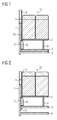
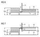
- FIGS. 3 to 7 respectively show partial cross-sectional views of an entry / exit area of a rail vehicle.
- the floor heights from FIGS. 3, 5, 6 correspond to the floor height in FIG. 1, while the floor heights from FIGS. 4 and 7 belong to the floor height from FIG.
- FIGS. 3 to 7 three different platform heights are shown in FIGS. 3 to 7 for illustrative purposes, the highest platform height being 760 mm, the average platform height being 550 mm and the lowest platform height being 380 mm above the upper edge of the rail S0.
- the floor 3 is in its initial height immediately above the car body substructure 2. Escape with the floor 3 is in the entry / exit area, which is illustrated by a door opening 13, a fixed tread 14 is provided, which is a change in height of Floor 3 follows.
- a door opening 13 For closing a lower portion of the door opening 13 is an intermediate piece 17, which closes the resulting by lifting the floor 3 gap to the car body base 2.
- the intermediate piece 17 is attached to the car body shell 1 on the respective sides of the door cutout 13 and connected to the car body shell 1 using a cold joining technique.
- Figures 3 and 4 thus allow an adaptation of the rail vehicle with respect to its floor height to the top and the middle platform height.
- FIGS. 5 and 7 in comparison with FIGS. 3 and 4, the fixed step 14 is replaced by an internal slide step 15, which serves to bridge a distance between an entry / exit edge of the door cutout 13 and a platform.
- the inside sliding step opposite to the floor 3 is arranged in alignment and follows the change in height.
- FIG. 6 an embodiment is provided in which an underfloor sliding step 16 is arranged below the vehicle body substructure 2.
- the underfloor sliding step 16 may also be supplemented in the embodiments according to FIGS. 5 and 7, so that the resulting overall construction permits use of the rail vehicle for all three platform heights.
Landscapes
- Engineering & Computer Science (AREA)
- Mechanical Engineering (AREA)
- Transportation (AREA)
- Life Sciences & Earth Sciences (AREA)
- Wood Science & Technology (AREA)
- Body Structure For Vehicles (AREA)
- Seats For Vehicles (AREA)
- Fittings On The Vehicle Exterior For Carrying Loads, And Devices For Holding Or Mounting Articles (AREA)
- Vehicle Cleaning, Maintenance, Repair, Refitting, And Outriggers (AREA)
Abstract
Description
Die Erfindung bezieht sich auf ein Schienenfahrzeug mit wenigstens einem Ein-/Ausstiegsbereich und einem Fußbodenaufbau. Ein solches Schienenfahrzeug entspricht dem typischen Aufbau von Schienenfahrzeugen, wobei in dem Ein-/Ausstiegsbereich naturgemäß eine Fahrzeugtür angeordnet ist, und zwar relativ zu einem Fußboden des Schienenfahrzeugs, so dass Fahrgäste das Schienenfahrzeug in geeigneter Art und Weise verlassen und betreten können.The invention relates to a rail vehicle with at least one entry / exit area and a floor structure. Such a rail vehicle corresponds to the typical structure of rail vehicles, wherein in the entry / exit area naturally a vehicle door is arranged, relative to a floor of the rail vehicle, so that passengers can leave the rail vehicle in a suitable manner and enter.
Bei Schienenfahrzeugen kann sich die Problematik ergeben, dass sie auf unterschiedlichen Gleisstrecken eingesetzt werden sollen, wobei die Höhe der der Gleisstrecke zugehörigenden Bahnsteige variieren kann. Unter solchen Umständen ist es erforderlich, den Ein-/Ausstiegsbereich so zu gestalten, dass verschiedenen Bahnsteighöhen Rechnung getragen werden kann. Dabei besteht allgemein die Aufgabe, für beispielsweise Rollstuhlfahrer oder gehbehinderte Personen einen ebenerdigen Einstieg zu ermöglichen. Zu diesem Zweck ist es bekannt, so genannte Einstiegshilfen einzusetzen, die im Ein-/Ausstiegsbereich angeordnet sind und dazu geeignet sind, in eingeschränktem Maße unterschiedliche Bahnsteighöhen auszugleichen oder den Einstieg in das Fahrzeug von verschiedenen Bahnsteighöhen aus zu ermögilchen.In rail vehicles, the problem may arise that they should be used on different track distances, the height of the track belonging to the platforms may vary. In such circumstances, it is necessary to design the entry / exit area so that different platform heights can be accommodated. It is generally the task, for example, wheelchair users or handicapped persons to enable a ground level entry. For this purpose, it is known to use so-called boarding aids, which are arranged in the entry / exit area and are adapted to compensate for different platform heights to a limited extent or to allow the entry into the vehicle from different platform heights.
Ausgehend hiervon liegt der Erfindung die Aufgabe zu Grunde, ein Schienenfahrzeug anzugeben, bei dem eine Anpassung an verschiedene vorgegebene Bahnsteighöhen vereinfacht wird.Proceeding from this, the object of the invention is to provide a rail vehicle in which an adaptation to different predetermined platform heights is simplified.
Diese Aufgabe wird bei einem eingangs genannten Schienenfahrzeug dadurch gelöst, dass der Fußbodenaufbau modular ausgeführt ist und Komponenten umfasst, die ein Anheben des Fußbodens aus einer Ausgangshöhenlage in eine andere Höhenlage gestatten.This object is achieved with a rail vehicle mentioned above in that the floor structure is modular and includes components that allow lifting of the floor from an initial altitude to another altitude.
In Folge der modularen Ausführung des Fußbodenaufbaus, der wenigstens zwei Höhenlagen des Fußbodens gestattet, ist es möglich, die Fußbodenhöhe an vorhandene Gegebenheiten von Bahnsteigen anzupassen. Auf diese Weise wird erreicht, dass ein derart ausgeführtes Schienenfahrzeug auf verschiedenen Gleisstrecken mit jeweils zugehöriger Bahnsteighöhe einsetzbar ist, und zwar durch entsprechende Um- bzw. Nachrüstung des Fußbodenaufbaus. Dabei wird von den Komponenten Gebrauch gemacht, die ein Anheben des Fußbodens aus einer Ausgangshöhenlage in eine andere Höhenlage gestatten. Dabei sind aus dem Stand der Technik Maßnahmen bekannt, den Fußboden in herkömmlicher Weise an Seitenwänden des Wagenkastenrohbaus anzubinden. Der hier vorgestellte modulare Fußbodenaufbau umfasst weitere Komponenten, die ein Anheben des Fußbodens ermöglichen, so dass dieser an einem typischer Weise höheren Platz an den Seitenwänden des Wagenkastenrohbaus befestigbar ist. Zu diesem Zweck ist es vorteilhaft, wenn der Fußbodenaufbau als Komponente eine Fußbodenabstützung umfasst, die zur seitlichen Befestigung des Fußbodens an dem Wagenkastenrohbau des Schienenfahrzeugs ausgebildet ist. Eine solche Fußbodenabstützung kann beispielsweise in Form eines Winkelprofils vorliegen, das mit seinem einen Schenkel an der Seitenwand des Wagenkastenrohbaus und mit seinem anderen Schenkel an der Unterseite des Fußbodens angebracht wird.As a result of the modular design of the floor structure, which allows at least two heights of the floor, it is possible to adapt the floor level to existing conditions of platforms. In this way it is achieved that such a running rail vehicle can be used on different track sections, each with associated platform height, through appropriate conversion or retrofitting of the floor structure. It is made use of the components that allow lifting of the floor from an initial altitude to another altitude. It is known from the prior art measures to bind the floor in a conventional manner on side walls of the car body shell. The modular floor structure presented here includes other components that allow the floor to be raised so that it can be fastened to the side walls of the carbody shell in a typically higher space. For this purpose, it is advantageous if the floor structure as a component comprises a floor support, which is designed for the lateral attachment of the floor to the car body shell of the rail vehicle. Such a floor support may for example be in the form of an angle profile, which is attached with its one leg to the side wall of the car body shell and with its other leg at the bottom of the floor.
Es ist von Vorteil, wenn die andere Höhenlage oberhalb der Ausgangshöhenlage liegt, denn in diesem Fall kann die Ausgangshöhenlage beispielsweise der technisch minimal realisierbaren Bahnsteighöhe angepasst sein, so dass in diesem Fall eine besonders einfache Gesamtkonstruktion vorliegt. Für weniger vertretende Bahnsteighöhen können dann Umrüst- bzw. Nachrüstmaßnahmen getroffen werden, um den Fußboden auf die geeignete Höhe anzuheben.It is advantageous if the other altitude is above the initial altitude, because in this case, the initial altitude, for example, be adapted to the technically minimum feasible platform height, so that in this case a particularly simple overall design is present. For less representative platform heights then retrofit or retrofit measures can be taken to raise the floor to the appropriate height.
Typischer Weise wird die Fußbodenabstützung zur Einnahme der anderen Höhenlage des Fußbodens in einem Zwischenraum zwischen der Fußbodenunterseite und einem Unterbau des Wagenkastenrohbaus angeordnet sein. Soweit erforderlich, können neben der Fußbodenabstützung zur Seitenwand hin weitere Stützelemente vorgesehen sein, die zwischen dem Wagenkastenunterbau und dem Fußboden verlaufen.Typically, the floor support will be arranged to take the other altitude of the floor in a space between the bottom floor and a substructure of the car body shell. If necessary, in addition to the floor support to the side wall further support elements may be provided which extend between the car body base and the floor.
Es ist hervorzuheben, dass Anbindungen zwischen Sitzträgern, Seitenwandbefestigungskonsolen und seitlichen Klimakanälen einerseits und dem Fußboden andererseits bei einer Änderung der Höhenlage des Fußbodens erhalten bleiben. Die genannten Innenraumelemente eines Schienenfahrzeugs werden somit im Fall einer Erhöhung der Fußbodenlage gemeinsam mit dem Fußboden entlang den Seitenwänden des Schienenfahrzeugs mit angehoben. Dies bedeutet, dass die Gesamtkonstruktion aus Fußboden und daran angebrachten Schienenfahrzeuginnenelementen für sämtliche möglichen Fußbodenhöhen identisch ist.It should be emphasized that connections between seat supports, side wall mounting brackets and side air ducts on the one hand and the floor on the other hand remain in a change in the altitude of the floor. The aforementioned interior elements of a rail vehicle are thus raised together with the floor along the side walls of the rail vehicle in case of an increase in the floor layer. This means that the overall construction of floor and rail vehicle interior elements attached to it is identical for all possible floor levels.
Für das letztgenannte Ausführungsbeispiel der Erfindung ist es günstig, wenn eine Seitenwandverkleidung des Schienenfahrzeugs ein zwischen einem Seitenwandverkleidungshauptteil und einem Klimakanal angeordnetes Ausgleichsstück aufweist, das aus der Seitenwandverkleidung entfernbar ist, um die Einnahme der anderen Höhenlage des Fußbodens zu gestatten. Ein solches Ausgleichsstück erstreckt sich dann jeweils in Längsrichtung der Seitenwände des Wagenkastenrohbaus. Vorgesehene Sitzträger können entweder an der Seitenwand lediglich abgestützt oder auch an der Seitenwand angebunden sein. Im ersteren Fall ist ein vertikales Versetzen der Sitzträger insgesamt mit einer Änderung der Fußbodenhöhe ermöglicht.For the latter embodiment of the invention, it is favorable if a side wall lining of the rail vehicle between a side wall panel main part and a climate channel arranged compensating piece, which is removable from the side wall paneling to allow the capture of the other altitude of the floor. Such a compensating piece then extends in each case in the longitudinal direction of the side walls of the Wagenkastenrohbaus. Provided seat support can either be supported only on the side wall or tied to the side wall. In the former case, a vertical displacement of the seat support is possible in total with a change in the floor level.
Es ergibt sich, dass eine Anhebung des Fußbodenniveaus unmittelbare Auswirkungen auf die Gestaltung eines Ein-/Ausstiegsbereichs eines Schienenfahrzeugs hat. Es ist daher vorgesehen, dass der Ein-/Ausstiegsbereich auf vorgegebene Bahnsteighöhen flexibel umrüstbar ist, wobei sowohl die Ausgangshöhenlage als auch die andere Höhenlage des Fußbodens jeweils an eine der vorgegebenen Bahnsteighöhen angepasst ist.It can be seen that raising the floor level has an immediate effect on the design of an entry / exit area of a rail vehicle. It is therefore envisaged that the entry / exit area can be flexibly converted to predetermined platform heights, wherein both the initial altitude and the other altitude of the floor is respectively adapted to one of the predetermined platform heights.
Bevorzugt weist der Wagenkastenrohbau für den Ein-/Ausstiegsbereich ein Zwischenstück zum Verschließen eines Rohbauausschnittes auf, der sich bei Einnahme der anderen Höhenlage des Fußbodens ergibt, und jeweils an die Ausgangshöhenlage oder die anderen Höhenlage des Fußbodens angepasste, nach- bzw. umrüstbare Türblätter vorgesehen sind. Allgemein gesprochen, ist der Ein-/Ausstiegsbereich derart auszuführen, dass sämtliche damit verbundenen Funktionen, wie das Öffnen und Schließen der Türen, unabhängig von einer gewählten Höhenlage des Fußbodens vorhanden sind. Dabei dient das Zwischenstück zur Abdichtung des Wagenkastenrohbaus in einem unteren Türöffnungsbereich, der durch das Anheben des Fußbodens aus dem ursprünglichen Türausschnitt zwangsläufig entsteht.Preferably, the Wagenkastenrohbau for the entry / exit area on an intermediate piece for closing a shell cutout, resulting in taking the other altitude of the floor, and respectively adapted to the initial altitude or the other altitude of the floor, nach- or convertible door leaves are provided , Generally speaking, the entry / exit area is to be designed such that all the associated functions, such as the opening and closing of the doors, are independent of a selected altitude of the floor. The intermediate piece is used to seal the Wagenkastenrohbaus in a lower door opening area, which inevitably arises from the raising of the floor from the original door opening.
Zur Erhöhung der Flexibilität gerade im Ein-/Ausstiegsbereich des Schienenfahrzeugs kann vorgesehen sein, dass, fluchtend mit dem Fußboden des Schienenfahrzeugs, eine Trittstufe vorgesehen ist, die an dem Fußboden angebracht ist, so dass sie einer Höhenveränderung des Fußbodens folgt. Statt der festen Trittstufe kann auch ein innen liegender Schiebetritt vorgesehen sein.To increase the flexibility, especially in the entry / exit area of the rail vehicle, it may be provided that, in alignment with the floor of the rail vehicle, a step is provided which is attached to the floor so as to follow a change in the height of the floor. Instead of the fixed tread, an internal sliding step can also be provided.
Zum Gewährleisten einer Anpassung an eine weitere vorgegebene Bahnsteighöhe kann unterhalb des Wagenkastenunterbaus ein Unterflur-Schiebetritt vorhanden sein.To ensure an adaptation to a further predetermined platform height, an underfloor sliding step may be provided below the carbody base.
Ausführungsbeispiele der Erfindung werden nachfolgend anhand der Zeichnungen noch näher erläutert. Es zeigen
- Figur 1
- eine Teil-Querschnittsansicht eines Schienenfahrzeugs mit einem in einer Ausgangshöhe befindlichen Fußboden,
Figur 2- eine Teil-Querschnittsansicht eines Schienenfahrzeugs mit einem Fußboden in gegenüber Figur 1 erhöhter Lage,
Figur 3- eine Teil-Querschnittsansicht eines Schienenfahrzeugs in einem Ein-/Ausstiegsbereich mit einem Fußboden in einer Ausgangshöhe,
- Figur 4
- eine Teil-Querschnittsansicht eines Schienenfahrzeugs in einem Ein-/Ausstiegsbereich mit einem gegenüber
Figur 3 erhöhten Fußboden, Figur 5- eine Teil-Querschnittsansicht eines Ein/Ausstiegsbereichs eines Schienenfahrzeugs mit einem Fußboden in einer Ausgangshöhenlage,
- Figur 6
- eine Teil-Querschnittsansicht eines Ein/Ausstiegsbereichs eines Schienenfahrzeugs mit gegenüber
Figur 5 zusätzlichem Unterflur-Schiebetritt und - Figur 7
- eine Teil-Querschnittsansicht eines Ein/Ausstiegsbereichs eines Schienenfahrzeugs mit gegenüber
Figur 5 erhöhtem Fußboden.
- FIG. 1
- a partial cross-sectional view of a rail vehicle with a floor located at an initial height,
- FIG. 2
- 2 is a partial cross-sectional view of a rail vehicle having a floor in an elevated position compared to FIG. 1;
- FIG. 3
- a partial cross-sectional view of a rail vehicle in an entry / exit area with a floor at an initial height,
- FIG. 4
- 1 is a partial cross-sectional view of a rail vehicle in an entry / exit area with a raised floor compared to FIG. 3;
- FIG. 5
- a partial cross-sectional view of an entry / exit area of a rail vehicle with a floor in an initial altitude position,
- FIG. 6
- a partial cross-sectional view of an entry / exit area of a rail vehicle with respect to Figure 5 additional under-floor Schiebetritt and
- FIG. 7
- a partial cross-sectional view of an entry / exit area of a rail vehicle with respect to Figure 5 elevated floor.
Die beiden Teil-Querschnittsansichten von Figur 1 und 2 betreffen einen Schienenfahrzeug-Innenraumbereich, in dem Sitze 12 für Fahrgäste untergebracht sind, d. h. die Ansichten liegen entfernt von einem Ein-/Ausstiegsbereich des Schienenfahrzeugs. In der Ansicht von Figur 1 ist ein Teil eines Wagenkastenrohbaus 1, ein Teil eines Wagenkastenunterbaus 2 und ein unmittelbar auf dem Wagenkastenunterbau 2 abgestützter Fußboden 3 in einer Ausgangshöhe dargestellt. Auf einer Innenseite des vertikalen Wagenkastenrohbaus 1 erstreckt sich eine Seitenwandinnenverkleidung 4. Im seitlichen Randbereich des Fußbodens 3 ist eine Befestigungskonsole 5 für einen Klimakanal 6 vorgesehen, wobei die Befestigungskonsole 5 und der Klimakanal 6 auf dem Fußboden 3 abgestützt sind. Dabei ist die Befestigungskonsole an der Seitenwand und/oder am Fußboden befestigt. Bei ausschließlicher Befestigung am Fußboden 3 lässt sich die Befestigungskonsole 5 bei Anheben des Fußbodens 3 ohne weiteres ebenfalls in der Höhe versetzen.The two partial cross-sectional views of FIGS. 1 and 2 relate to a rail vehicle interior area in which
Ein Sitzträger 7 ist im Bereich der Seitenwandinnenverkleidung 4 an einer Oberseite der Befestigungskonsole 5 angebracht und stützt sich außerdem über ein Stützelement 8 auf dem Fußboden 3 ab.A seat support 7 is mounted in the region of the side wall inner panel 4 on an upper side of the mounting
Zwischen der Oberseite der Befestigungskonsole 5 für den Klimakanal 6 und einem unteren Ende eines Hauptteils 9 der Seiteninnenwandverkleidung erstreckt sich ein ggf. mehrteiliges Ausgleichsstück 10, das in horizontaler Richtung entlang dem Schienenfahrzeug verläuft.Between the top of the mounting
Für den Fußbodenaufbau ist eine modulare Ausführung vorgesehen, die, wie in Figur 2 veranschaulicht ist, eine Fußbodenabstützung 11 in Form eines Winkelprofils umfasst. Sofern das Schienenfahrzeug nach Figur 1 hinsichtlich der Höhenlage seines Fußbodens 3 an eine vorgegebene Bahnsteighöhe angepasst ist, kann mit Hilfe der Fußbodenabstützung 11 der Fußboden 3 auf eine Höhe gebracht werden, die einer weiteren vorgegebenen Bahnsteighöhe entspricht. Wie in Figur 2 zu sehen ist, liegt der Fußboden 3 nicht mehr unmittelbar auf dem Wagenkastenunterbau 2 auf, sondern befindet sich dazu in einem Abstand, wobei die Fußbodenabstützung 11 mit ihrem einen Schenkel unter einen Rand des Fußbodens 3 greift, während der andere Schenkel an dem vertikalen Wagenkastenrohbau 1 angebracht ist (formkraftschlüssige Verbindung).For the floor construction, a modular design is provided, which, as illustrated in FIG. 2, comprises a floor support 11 in the form of an angle profile. If the rail vehicle according to FIG. 1 is adapted to a predetermined platform height with regard to the altitude of its
Mit Erhöhen der Lage des Fußbodens 3 entfällt das anhand der Figur 1 veranschaulichte Ausgleichsstück 10, so dass nunmehr der Hauptteil 9 der Seitenwandinnenverkleidung 4 und die Oberseite der Befestigungskonsole 5 für den Klimakanal 6 unmittelbar aneinander anschließen. Bei beiden anhand der Figuren 1 und 2 erläuterten Ausführungsformen der Erfindung bleiben die relativen Lagen des Fußbodens 3 der Befestigungskonsole 5 und des Sitzträgers 7 mit darauf befindlichen Sitzen 12 zueinander erhalten. Es reicht somit eine Erhöhung des Fußbodens 3 mit Hilfe der Fußbodenabstützung 11 aus, um ohne erhebliche Änderungen in der Gesamtkonstruktion eines Schienenfahrzeugs eine Anpassung von einer Ausgangsbahnsteighöhe zu einem erhöhten Bahnsteigniveau vorzunehmen.With increasing the position of the
Die Figuren 3 bis 7 zeigen jeweils Teil-Querschnittsansichten eines Ein-/Ausstiegsbereichs eines Schienenfahrzeugs. Dabei entsprechen die Fußbodenhöhen aus den Figuren 3, 5, 6 der Fußbodenhöhe in Figur 1, während die Fußbodenhöhen aus den Figuren 4 und 7 der Fußbodenhöhe von Figur 2 zugehörig sind.FIGS. 3 to 7 respectively show partial cross-sectional views of an entry / exit area of a rail vehicle. The floor heights from FIGS. 3, 5, 6 correspond to the floor height in FIG. 1, while the floor heights from FIGS. 4 and 7 belong to the floor height from FIG.
Außerdem sind in den Figuren 3 bis 7 zu Veranschaulichungszwecken drei verschieden Bahnsteighöhen dargestellt, wobei die oberste Bahnsteighöhe 760 mm, die mittlere Bahnsteighöhe 550 mm und die unterste Bahnsteighöhe 380 mm über der Schienenoberkante S0 liegt.In addition, three different platform heights are shown in FIGS. 3 to 7 for illustrative purposes, the highest platform height being 760 mm, the average platform height being 550 mm and the lowest platform height being 380 mm above the upper edge of the rail S0.
Bei der Ausführungsform nach Figur 3 befindet sich der Fußboden 3 in seiner Ausgangshöhe unmittelbar über dem Wagenkastenunterbau 2. Fluchtend mit dem Fußboden 3 ist im Ein-/Ausstiegsbereich, der durch einen Türausschnitt 13 veranschaulicht ist, eine feste Trittstufe 14 vorgesehen, die einer Höhenänderung des Fußbodens 3 folgt. Letzteres geht deutlich aus Figur 4 hervor, bei der der Fußboden 3 mit Hilfe der in Figur 2 gezeigten Fußbodenabstützung 11 auf ein höheres Niveau gebracht worden ist. Zum Verschließen eines unteren Abschnitts des Türausschnitts 13 dient ein Zwischenstück 17, das die durch das Anheben des Fußbodens 3 entstehende Lücke zum Wagenkastenunterbau 2 schließt. Für beide gezeigten Fußbodenhöhen ist jeweils ein anderer Satz Türblätter maßgeblich, die Bestandteil der Komponenten des modularen Aufbaus des Schienenfahrzeugs zur Anpassung an die verschiedenen Bahnsteighöhen sind. Das Zwischenstück 17 ist an dem Wagenkastenrohbau 1 an den jeweiligen Seiten des Türausschnitts 13 angebracht und mit dem Wagenkastenrohbau 1 unter Verwendung einer Kaltfügetechnik verbunden.In the embodiment of Figure 3, the
Die Ausführungsformen der Figuren 3 und 4 gestatten somit eine Anpassung des Schienenfahrzeugs hinsichtlich seiner Fußbodenhöhe an die oberste und die mittlere Bahnsteighöhe.The embodiments of Figures 3 and 4 thus allow an adaptation of the rail vehicle with respect to its floor height to the top and the middle platform height.
In den Figuren 5 und 7 ist im Vergleich zu den Figuren 3 und 4 die feste Trittstufe 14 durch einen innen liegenden Schiebetritt 15 ersetzt, der zum Überbrücken eines Abstandes zwischen einer Ein-/Ausstiegskante des Türausschnitts 13 und einem Bahnsteig dient. Ebenso wie die feste Trittstufe 14 ist der innen liegende Schiebetritt gegenüber dem Fußboden 3 fluchtend angeordnet und folgt dessen Höhenänderung. Zur Anpassung an die unterste Bahnsteighöhe ist in Figur 6 eine Ausführungsform vorgesehen, bei der ein Unterflur-Schiebetritt 16 unterhalb des Wagenkastenunterbaus 2 angeordnet ist. Selbstverständlich kann der Unterflur-Schiebetritt 16 auch bei den Ausführungsformen nach den Figuren 5 und 7 ergänzt sein, so dass die daraus entstehende Gesamtkonstruktion eine Verwendung des Schienenfahrzeugs für sämtliche drei Bahnsteighöhen gestattet.In FIGS. 5 and 7, in comparison with FIGS. 3 and 4, the fixed
Claims (11)
dadurch gekennzeichnet,
dass der Fußbodenaufbau modular ausgeführt ist und Komponenten umfasst, die ein Anheben eines Fußbodens (3) aus einer Ausgangshöhenlage in eine andere Höhenlage relativ zu einem Wagenkastenrohbau (1) gestatten.Railway vehicle with at least one entry / exit area and a floor structure,
characterized,
that the floor structure is modular and comprises components which allow lifting of a floor (3) from an initial height position to a different altitude relative to a car body shell (1).
dadurch gekennzeichnet,
dass die andere Höhenlage oberhalb der Ausgangshöhenlage liegt.Rail vehicle according to claim 1,
characterized,
that the other altitude is above the initial altitude.
dadurch gekennzeichnet,
dass der Fußbodenaufbau als Komponente eine Fußbodenabstützung (11) umfasst, die zur seitlichen Befestigung des Fußbodens (3) an dem Wagenkastenrohbau (1) des Schienenfahrzeugs ausgebildet ist.Rail vehicle according to claim 1 or 2,
characterized,
in that the floor structure comprises, as a component, a floor support (11) which is designed for the lateral attachment of the floor (3) to the vehicle body shell (1) of the rail vehicle.
dadurch gekennzeichnet,
dass die Fußbodenabstützung (11) zur Einnahme der anderen Höhenlage des Fußbodens in einem Zwischenraum zwischen der Fußbodenunterseite und einem Unterbau des Wagenkastenrohbaus (2) angeordnet ist.Rail vehicle according to claim 3,
characterized,
in that the floor support (11) for taking up the other vertical position of the floor is arranged in a space between the bottom floor and a substructure of the vehicle body shell (2).
dadurch gekennzeichnet,
dass Anbindungen zwischen Sitzträgern (7), Seitenwandbefestigungskonsolen (5) und seitlichen Klimakanälen (6) einerseits und dem Fußboden (3) andererseits bei einer Änderung der Höhenlage des Fußbodens (3) erhalten bleiben.Rail vehicle according to one of claims 1 to 4,
characterized,
that connections between seat supports (7), side wall mounting brackets (5) and lateral Air ducts (6) on the one hand and the floor (3) on the other hand with a change in the altitude of the floor (3) are maintained.
dadurch gekennzeichnet,
dass eine Seitenwandverkleidung (9; 10) des Schienenfahrzeugs ein zwischen einem Seitenwandverkleidungshauptteil (9) und einem Klimakanal (6) angeordnetes Ausgleichsstück (10) aufweist, das aus der Seitenwandverkleidung (9, 10) entfernbar ist, um die Einnahme der anderen Höhenlage des Fußbodens (3) zu gestatten.Rail vehicle according to one of claims 1 to 5,
characterized,
in that a sidewall covering (9; 10) of the rail vehicle comprises a compensating piece (10) arranged between a side wall lining main part (9) and an air conditioning duct (6), which is removable from the side wall covering (9, 10) to take up the other height position of the floor (3) to allow.
dadurch gekennzeichnet,
dass der Ein-/Ausstiegsbereich auf vorgegebene Bahnsteighöhen flexibel umrüstbar ist, wobei sowohl die Ausgangshöhenlage als auch die andere Höhenlage jeweils einer der vorgegebenen Bahnsteighöhen angepasst ist.Rail vehicle according to one of claims 1 to 6,
characterized,
that the entry / exit area can be flexibly converted to predetermined platform heights, wherein both the initial altitude and the other altitude are each adapted to one of the predetermined platform heights.
dadurch gekennzeichnet,
dass der Wagenkastenrohbau (1) für den Ein-/Ausstiegsbereich ein Zwischenstück (17) zum Verschließen eines Rohbauausschnittes aufweist, der sich bei Einnahme der anderen Höhenlage des Fußbodens (3) ergibt, und jeweils an die Ausgangshöhenlage oder die andere Höhenlage des Fußbodens (3) angepasste, nach- bzw. umrüstbare Türblätter vorgesehen sind.Rail vehicle according to one of claims 1 to 7,
characterized,
in that the car body shell (1) for the entry / exit area has an intermediate piece (17) for closing a body cutout resulting from taking up the other vertical position of the floor (3) and respectively at the initial height position or the other height position of the floor (3 ) adapted, nach- or convertible door leaves are provided.
dadurch gekennzeichnet,
dass, fluchtend mit dem Fußboden (3) des Schienenfahrzeugs in dem Ein-/Ausstiegsbereich eine an dem Fußboden (3) angebrachte Trittstufe (14) vorgesehen ist.Rail vehicle according to one of claims 1 to 8,
characterized,
in that , in alignment with the floor (3) of the rail vehicle, a step (14) attached to the floor (3) is provided in the entry / exit area.
dadurch gekennzeichnet,
dass, fluchtend mit dem Fußboden (3) des Schienenfahrzeugs, ein an dem Fußboden (3) angebrachter innen liegender Schiebetritt (15) im Ein-/Ausstiegsbereich des Schienenfahrzeugs vorgesehen ist.Rail vehicle according to one of claims 1 to 8,
characterized,
in that , in alignment with the floor (3) of the rail vehicle, an internal sliding step (15), which is attached to the floor (3), is provided in the entry / exit area of the rail vehicle.
dadurch gekennzeichnet,
dass unterhalb des Wagenkastenunterbaus (2) ein Unterflur-Schiebetritt (16) im Ein-/Ausstiegsbereich vorgesehen ist.Rail vehicle according to one of claims 9 or 10,
characterized,
in that below the carbody substructure (2) an underfloor sliding step (16) is provided in the entry / exit area.
Applications Claiming Priority (1)
| Application Number | Priority Date | Filing Date | Title |
|---|---|---|---|
| DE102006001807A DE102006001807A1 (en) | 2006-01-12 | 2006-01-12 | Rail vehicle, has flooring construction designed as modular flooring and including support that enables lifting of flooring from exit height to other height relative to body shell of vehicle, where latter height is above exit height |
Publications (2)
| Publication Number | Publication Date |
|---|---|
| EP1808352A1 true EP1808352A1 (en) | 2007-07-18 |
| EP1808352B1 EP1808352B1 (en) | 2009-03-11 |
Family
ID=37741937
Family Applications (1)
| Application Number | Title | Priority Date | Filing Date |
|---|---|---|---|
| EP07100197A Not-in-force EP1808352B1 (en) | 2006-01-12 | 2007-01-08 | Rail vehicle having at least an access platform and a modular floor construction |
Country Status (3)
| Country | Link |
|---|---|
| EP (1) | EP1808352B1 (en) |
| AT (1) | ATE425056T1 (en) |
| DE (2) | DE102006001807A1 (en) |
Cited By (2)
| Publication number | Priority date | Publication date | Assignee | Title |
|---|---|---|---|---|
| WO2014118026A1 (en) * | 2013-01-29 | 2014-08-07 | Siemens Aktiengesellschaft | Rail vehicle |
| EP3712030A1 (en) * | 2019-03-18 | 2020-09-23 | ALSTOM Transport Technologies | Railway vehicle with adjustable floor height |
Families Citing this family (2)
| Publication number | Priority date | Publication date | Assignee | Title |
|---|---|---|---|---|
| DE102011018618B4 (en) | 2010-04-21 | 2016-03-24 | Technische Universität Kaiserslautern | Easy entry |
| DE102014207349B4 (en) | 2014-04-16 | 2022-01-13 | Stadler Pankow GmbH | Adjusting device for adjusting the height of an extendable step element on a vehicle |
Citations (2)
| Publication number | Priority date | Publication date | Assignee | Title |
|---|---|---|---|---|
| DE19914965A1 (en) * | 1999-04-01 | 2000-10-05 | Alstom Lhb Gmbh | Passenger access for railway vehicles consists of raiseable platform between carriage doors, to align with station platforms of different heights |
| WO2001030630A1 (en) * | 1999-10-27 | 2001-05-03 | Deutsche Bahn Ag | Rail mounted vehicle segment with a centrifugal force compensation device integrated into the body thereof |
-
2006
- 2006-01-12 DE DE102006001807A patent/DE102006001807A1/en not_active Withdrawn
-
2007
- 2007-01-08 AT AT07100197T patent/ATE425056T1/en active
- 2007-01-08 DE DE502007000482T patent/DE502007000482D1/en active Active
- 2007-01-08 EP EP07100197A patent/EP1808352B1/en not_active Not-in-force
Patent Citations (2)
| Publication number | Priority date | Publication date | Assignee | Title |
|---|---|---|---|---|
| DE19914965A1 (en) * | 1999-04-01 | 2000-10-05 | Alstom Lhb Gmbh | Passenger access for railway vehicles consists of raiseable platform between carriage doors, to align with station platforms of different heights |
| WO2001030630A1 (en) * | 1999-10-27 | 2001-05-03 | Deutsche Bahn Ag | Rail mounted vehicle segment with a centrifugal force compensation device integrated into the body thereof |
Cited By (3)
| Publication number | Priority date | Publication date | Assignee | Title |
|---|---|---|---|---|
| WO2014118026A1 (en) * | 2013-01-29 | 2014-08-07 | Siemens Aktiengesellschaft | Rail vehicle |
| EP2951071B1 (en) | 2013-01-29 | 2017-03-08 | Siemens Aktiengesellschaft | Rail vehicle |
| EP3712030A1 (en) * | 2019-03-18 | 2020-09-23 | ALSTOM Transport Technologies | Railway vehicle with adjustable floor height |
Also Published As
| Publication number | Publication date |
|---|---|
| EP1808352B1 (en) | 2009-03-11 |
| DE502007000482D1 (en) | 2009-04-23 |
| DE102006001807A1 (en) | 2007-07-19 |
| ATE425056T1 (en) | 2009-03-15 |
Similar Documents
| Publication | Publication Date | Title |
|---|---|---|
| DE60103069T2 (en) | Double-decker railway wagons with passage facilities in both floors | |
| EP2641805B1 (en) | Rail vehicle with an entry designed for persons with reduced mobility | |
| DE4442368C2 (en) | Double-decker rail vehicle | |
| EP3868626B1 (en) | Passenger transport vehicle | |
| EP1808352B1 (en) | Rail vehicle having at least an access platform and a modular floor construction | |
| EP2060469B1 (en) | Double decker rail vehicle | |
| DE102005057901B4 (en) | Rail vehicle with sliding step arranged in the entry area | |
| DE69927010T2 (en) | LIFTING DEVICE FOR RAIL VEHICLES | |
| WO2014063892A1 (en) | Two-level rail vehicle | |
| DE4137450A1 (en) | ENTRANCE OR EXIT SYSTEM FOR VEHICLES | |
| DE19914965B4 (en) | Person entry for rail vehicles | |
| DE102009024510A1 (en) | Rail vehicle and method for operating a rail vehicle | |
| EP2951071B1 (en) | Rail vehicle | |
| EP2792568A1 (en) | Multi-part rail vehicle | |
| DE10113074A1 (en) | Device for bridging level differences when entering and leaving vehicles has horizontal platform which in relation to level of floor of vehicle is movable upwards to higher level and also downwards to lower level | |
| DE102012220274A1 (en) | Rail vehicle with a lifting platform in the entry area | |
| EP2653143B1 (en) | Coach with a lifting device as an aid to entry for a wheelchair user | |
| EP3538410B1 (en) | Rail vehicle having interior portions at different floor levels | |
| DE3406609A1 (en) | Superstructure for passenger carriages for railways, local-traffic railways, magnetic levitation railways etc. | |
| EP3909825B1 (en) | Railway vehicles with upper deck, lower deck and mezzanine level | |
| DE4239882A1 (en) | Track-bound vehicle | |
| EP0567509B1 (en) | Passenger car with lateral door sills | |
| EP3737598B1 (en) | Vehicle bridge body and multiple-unit rail vehicle | |
| DE19955877A1 (en) | Method for getting on and off a passenger vehicle like a low-platform tramcar has an accessible platform floor partially covering a vehicle undercarriage and a passenger lift with a platform raised and lowered by a lifting mechanism. | |
| DE102015110589A1 (en) | Auxiliary device for facilitating the entry and exit of a disabled vehicle in and out of a passenger transport |
Legal Events
| Date | Code | Title | Description |
|---|---|---|---|
| PUAI | Public reference made under article 153(3) epc to a published international application that has entered the european phase |
Free format text: ORIGINAL CODE: 0009012 |
|
| AK | Designated contracting states |
Kind code of ref document: A1 Designated state(s): AT BE BG CH CY CZ DE DK EE ES FI FR GB GR HU IE IS IT LI LT LU LV MC NL PL PT RO SE SI SK TR |
|
| AX | Request for extension of the european patent |
Extension state: AL BA HR MK YU |
|
| 17P | Request for examination filed |
Effective date: 20080115 |
|
| 17Q | First examination report despatched |
Effective date: 20080218 |
|
| AKX | Designation fees paid |
Designated state(s): AT BE BG CH CY CZ DE DK EE ES FI FR GB GR HU IE IS IT LI LT LU LV MC NL PL PT RO SE SI SK TR |
|
| GRAP | Despatch of communication of intention to grant a patent |
Free format text: ORIGINAL CODE: EPIDOSNIGR1 |
|
| GRAS | Grant fee paid |
Free format text: ORIGINAL CODE: EPIDOSNIGR3 |
|
| GRAA | (expected) grant |
Free format text: ORIGINAL CODE: 0009210 |
|
| AK | Designated contracting states |
Kind code of ref document: B1 Designated state(s): AT BE BG CH CY CZ DE DK EE ES FI FR GB GR HU IE IS IT LI LT LU LV MC NL PL PT RO SE SI SK TR |
|
| REG | Reference to a national code |
Ref country code: GB Ref legal event code: FG4D Free format text: NOT ENGLISH |
|
| REG | Reference to a national code |
Ref country code: CH Ref legal event code: NV Representative=s name: SIEMENS SCHWEIZ AG Ref country code: CH Ref legal event code: EP |
|
| REG | Reference to a national code |
Ref country code: IE Ref legal event code: FG4D Free format text: LANGUAGE OF EP DOCUMENT: GERMAN |
|
| REF | Corresponds to: |
Ref document number: 502007000482 Country of ref document: DE Date of ref document: 20090423 Kind code of ref document: P |
|
| PG25 | Lapsed in a contracting state [announced via postgrant information from national office to epo] |
Ref country code: FI Free format text: LAPSE BECAUSE OF FAILURE TO SUBMIT A TRANSLATION OF THE DESCRIPTION OR TO PAY THE FEE WITHIN THE PRESCRIBED TIME-LIMIT Effective date: 20090311 Ref country code: LT Free format text: LAPSE BECAUSE OF FAILURE TO SUBMIT A TRANSLATION OF THE DESCRIPTION OR TO PAY THE FEE WITHIN THE PRESCRIBED TIME-LIMIT Effective date: 20090311 Ref country code: SI Free format text: LAPSE BECAUSE OF FAILURE TO SUBMIT A TRANSLATION OF THE DESCRIPTION OR TO PAY THE FEE WITHIN THE PRESCRIBED TIME-LIMIT Effective date: 20090311 Ref country code: NL Free format text: LAPSE BECAUSE OF FAILURE TO SUBMIT A TRANSLATION OF THE DESCRIPTION OR TO PAY THE FEE WITHIN THE PRESCRIBED TIME-LIMIT Effective date: 20090311 |
|
| NLV1 | Nl: lapsed or annulled due to failure to fulfill the requirements of art. 29p and 29m of the patents act | ||
| PG25 | Lapsed in a contracting state [announced via postgrant information from national office to epo] |
Ref country code: LV Free format text: LAPSE BECAUSE OF FAILURE TO SUBMIT A TRANSLATION OF THE DESCRIPTION OR TO PAY THE FEE WITHIN THE PRESCRIBED TIME-LIMIT Effective date: 20090311 Ref country code: SE Free format text: LAPSE BECAUSE OF FAILURE TO SUBMIT A TRANSLATION OF THE DESCRIPTION OR TO PAY THE FEE WITHIN THE PRESCRIBED TIME-LIMIT Effective date: 20090611 Ref country code: PL Free format text: LAPSE BECAUSE OF FAILURE TO SUBMIT A TRANSLATION OF THE DESCRIPTION OR TO PAY THE FEE WITHIN THE PRESCRIBED TIME-LIMIT Effective date: 20090311 |
|
| REG | Reference to a national code |
Ref country code: IE Ref legal event code: FD4D |
|
| PG25 | Lapsed in a contracting state [announced via postgrant information from national office to epo] |
Ref country code: IE Free format text: LAPSE BECAUSE OF FAILURE TO SUBMIT A TRANSLATION OF THE DESCRIPTION OR TO PAY THE FEE WITHIN THE PRESCRIBED TIME-LIMIT Effective date: 20090311 Ref country code: EE Free format text: LAPSE BECAUSE OF FAILURE TO SUBMIT A TRANSLATION OF THE DESCRIPTION OR TO PAY THE FEE WITHIN THE PRESCRIBED TIME-LIMIT Effective date: 20090311 Ref country code: PT Free format text: LAPSE BECAUSE OF FAILURE TO SUBMIT A TRANSLATION OF THE DESCRIPTION OR TO PAY THE FEE WITHIN THE PRESCRIBED TIME-LIMIT Effective date: 20090824 Ref country code: ES Free format text: LAPSE BECAUSE OF FAILURE TO SUBMIT A TRANSLATION OF THE DESCRIPTION OR TO PAY THE FEE WITHIN THE PRESCRIBED TIME-LIMIT Effective date: 20090622 Ref country code: CZ Free format text: LAPSE BECAUSE OF FAILURE TO SUBMIT A TRANSLATION OF THE DESCRIPTION OR TO PAY THE FEE WITHIN THE PRESCRIBED TIME-LIMIT Effective date: 20090311 |
|
| PG25 | Lapsed in a contracting state [announced via postgrant information from national office to epo] |
Ref country code: RO Free format text: LAPSE BECAUSE OF FAILURE TO SUBMIT A TRANSLATION OF THE DESCRIPTION OR TO PAY THE FEE WITHIN THE PRESCRIBED TIME-LIMIT Effective date: 20090311 Ref country code: SK Free format text: LAPSE BECAUSE OF FAILURE TO SUBMIT A TRANSLATION OF THE DESCRIPTION OR TO PAY THE FEE WITHIN THE PRESCRIBED TIME-LIMIT Effective date: 20090311 Ref country code: IS Free format text: LAPSE BECAUSE OF FAILURE TO SUBMIT A TRANSLATION OF THE DESCRIPTION OR TO PAY THE FEE WITHIN THE PRESCRIBED TIME-LIMIT Effective date: 20090711 |
|
| PLBE | No opposition filed within time limit |
Free format text: ORIGINAL CODE: 0009261 |
|
| STAA | Information on the status of an ep patent application or granted ep patent |
Free format text: STATUS: NO OPPOSITION FILED WITHIN TIME LIMIT |
|
| PG25 | Lapsed in a contracting state [announced via postgrant information from national office to epo] |
Ref country code: DK Free format text: LAPSE BECAUSE OF FAILURE TO SUBMIT A TRANSLATION OF THE DESCRIPTION OR TO PAY THE FEE WITHIN THE PRESCRIBED TIME-LIMIT Effective date: 20090311 Ref country code: BG Free format text: LAPSE BECAUSE OF FAILURE TO SUBMIT A TRANSLATION OF THE DESCRIPTION OR TO PAY THE FEE WITHIN THE PRESCRIBED TIME-LIMIT Effective date: 20090611 |
|
| 26N | No opposition filed |
Effective date: 20091214 |
|
| PG25 | Lapsed in a contracting state [announced via postgrant information from national office to epo] |
Ref country code: MC Free format text: LAPSE BECAUSE OF NON-PAYMENT OF DUE FEES Effective date: 20100131 |
|
| PG25 | Lapsed in a contracting state [announced via postgrant information from national office to epo] |
Ref country code: GR Free format text: LAPSE BECAUSE OF FAILURE TO SUBMIT A TRANSLATION OF THE DESCRIPTION OR TO PAY THE FEE WITHIN THE PRESCRIBED TIME-LIMIT Effective date: 20090612 |
|
| PG25 | Lapsed in a contracting state [announced via postgrant information from national office to epo] |
Ref country code: IT Free format text: LAPSE BECAUSE OF FAILURE TO SUBMIT A TRANSLATION OF THE DESCRIPTION OR TO PAY THE FEE WITHIN THE PRESCRIBED TIME-LIMIT Effective date: 20090311 |
|
| PG25 | Lapsed in a contracting state [announced via postgrant information from national office to epo] |
Ref country code: CY Free format text: LAPSE BECAUSE OF FAILURE TO SUBMIT A TRANSLATION OF THE DESCRIPTION OR TO PAY THE FEE WITHIN THE PRESCRIBED TIME-LIMIT Effective date: 20090311 |
|
| PG25 | Lapsed in a contracting state [announced via postgrant information from national office to epo] |
Ref country code: LU Free format text: LAPSE BECAUSE OF NON-PAYMENT OF DUE FEES Effective date: 20100108 Ref country code: HU Free format text: LAPSE BECAUSE OF FAILURE TO SUBMIT A TRANSLATION OF THE DESCRIPTION OR TO PAY THE FEE WITHIN THE PRESCRIBED TIME-LIMIT Effective date: 20090912 |
|
| PG25 | Lapsed in a contracting state [announced via postgrant information from national office to epo] |
Ref country code: TR Free format text: LAPSE BECAUSE OF FAILURE TO SUBMIT A TRANSLATION OF THE DESCRIPTION OR TO PAY THE FEE WITHIN THE PRESCRIBED TIME-LIMIT Effective date: 20090311 |
|
| PGFP | Annual fee paid to national office [announced via postgrant information from national office to epo] |
Ref country code: AT Payment date: 20131211 Year of fee payment: 8 Ref country code: BE Payment date: 20140214 Year of fee payment: 8 |
|
| PGFP | Annual fee paid to national office [announced via postgrant information from national office to epo] |
Ref country code: CH Payment date: 20140407 Year of fee payment: 8 |
|
| PG25 | Lapsed in a contracting state [announced via postgrant information from national office to epo] |
Ref country code: BE Free format text: LAPSE BECAUSE OF NON-PAYMENT OF DUE FEES Effective date: 20150131 |
|
| REG | Reference to a national code |
Ref country code: CH Ref legal event code: PL |
|
| REG | Reference to a national code |
Ref country code: AT Ref legal event code: MM01 Ref document number: 425056 Country of ref document: AT Kind code of ref document: T Effective date: 20150108 |
|
| PG25 | Lapsed in a contracting state [announced via postgrant information from national office to epo] |
Ref country code: LI Free format text: LAPSE BECAUSE OF NON-PAYMENT OF DUE FEES Effective date: 20150131 Ref country code: CH Free format text: LAPSE BECAUSE OF NON-PAYMENT OF DUE FEES Effective date: 20150131 |
|
| PG25 | Lapsed in a contracting state [announced via postgrant information from national office to epo] |
Ref country code: AT Free format text: LAPSE BECAUSE OF NON-PAYMENT OF DUE FEES Effective date: 20150108 |
|
| REG | Reference to a national code |
Ref country code: FR Ref legal event code: PLFP Year of fee payment: 10 |
|
| PGFP | Annual fee paid to national office [announced via postgrant information from national office to epo] |
Ref country code: DE Payment date: 20160321 Year of fee payment: 10 |
|
| PGFP | Annual fee paid to national office [announced via postgrant information from national office to epo] |
Ref country code: GB Payment date: 20160111 Year of fee payment: 10 Ref country code: FR Payment date: 20160115 Year of fee payment: 10 |
|
| REG | Reference to a national code |
Ref country code: DE Ref legal event code: R119 Ref document number: 502007000482 Country of ref document: DE |
|
| GBPC | Gb: european patent ceased through non-payment of renewal fee |
Effective date: 20170108 |
|
| REG | Reference to a national code |
Ref country code: FR Ref legal event code: ST Effective date: 20170929 |
|
| PG25 | Lapsed in a contracting state [announced via postgrant information from national office to epo] |
Ref country code: FR Free format text: LAPSE BECAUSE OF NON-PAYMENT OF DUE FEES Effective date: 20170131 |
|
| PG25 | Lapsed in a contracting state [announced via postgrant information from national office to epo] |
Ref country code: GB Free format text: LAPSE BECAUSE OF NON-PAYMENT OF DUE FEES Effective date: 20170108 Ref country code: DE Free format text: LAPSE BECAUSE OF NON-PAYMENT OF DUE FEES Effective date: 20170801 |