EP1808246B1 - Futter für drehantreibbare Werkzeuge - Google Patents
Futter für drehantreibbare Werkzeuge Download PDFInfo
- Publication number
- EP1808246B1 EP1808246B1 EP06024977A EP06024977A EP1808246B1 EP 1808246 B1 EP1808246 B1 EP 1808246B1 EP 06024977 A EP06024977 A EP 06024977A EP 06024977 A EP06024977 A EP 06024977A EP 1808246 B1 EP1808246 B1 EP 1808246B1
- Authority
- EP
- European Patent Office
- Prior art keywords
- chuck
- insert
- sleeve
- lock bolt
- receptacle
- Prior art date
- Legal status (The legal status is an assumption and is not a legal conclusion. Google has not performed a legal analysis and makes no representation as to the accuracy of the status listed.)
- Not-in-force
Links
- 238000005461 lubrication Methods 0.000 claims abstract description 14
- 239000000314 lubricant Substances 0.000 claims abstract description 8
- 239000002826 coolant Substances 0.000 claims abstract description 7
- 238000003780 insertion Methods 0.000 description 5
- 230000037431 insertion Effects 0.000 description 5
- 230000002093 peripheral effect Effects 0.000 description 4
- 238000013016 damping Methods 0.000 description 3
- 230000005540 biological transmission Effects 0.000 description 2
- 238000005520 cutting process Methods 0.000 description 2
- 230000000694 effects Effects 0.000 description 2
- 229920001971 elastomer Polymers 0.000 description 2
- 239000000806 elastomer Substances 0.000 description 2
- 238000003754 machining Methods 0.000 description 2
- 238000010079 rubber tapping Methods 0.000 description 2
- 244000089486 Phragmites australis subsp australis Species 0.000 description 1
- 230000006978 adaptation Effects 0.000 description 1
- 239000000443 aerosol Substances 0.000 description 1
- 238000010276 construction Methods 0.000 description 1
- 230000001419 dependent effect Effects 0.000 description 1
- 238000010438 heat treatment Methods 0.000 description 1
- 230000001771 impaired effect Effects 0.000 description 1
- 238000007789 sealing Methods 0.000 description 1
- 230000007704 transition Effects 0.000 description 1
Images

Classifications
-
- B—PERFORMING OPERATIONS; TRANSPORTING
- B23—MACHINE TOOLS; METAL-WORKING NOT OTHERWISE PROVIDED FOR
- B23B—TURNING; BORING
- B23B31/00—Chucks; Expansion mandrels; Adaptations thereof for remote control
- B23B31/02—Chucks
- B23B31/028—Chucks the axial positioning of the tool being adjustable
-
- B—PERFORMING OPERATIONS; TRANSPORTING
- B23—MACHINE TOOLS; METAL-WORKING NOT OTHERWISE PROVIDED FOR
- B23B—TURNING; BORING
- B23B29/00—Holders for non-rotary cutting tools; Boring bars or boring heads; Accessories for tool holders
- B23B29/04—Tool holders for a single cutting tool
- B23B29/046—Tool holders for a single cutting tool with an intermediary toolholder
-
- B—PERFORMING OPERATIONS; TRANSPORTING
- B23—MACHINE TOOLS; METAL-WORKING NOT OTHERWISE PROVIDED FOR
- B23B—TURNING; BORING
- B23B31/00—Chucks; Expansion mandrels; Adaptations thereof for remote control
- B23B31/02—Chucks
- B23B31/10—Chucks characterised by the retaining or gripping devices or their immediate operating means
- B23B31/103—Retention by pivotal elements, e.g. catches, pawls
-
- B—PERFORMING OPERATIONS; TRANSPORTING
- B23—MACHINE TOOLS; METAL-WORKING NOT OTHERWISE PROVIDED FOR
- B23B—TURNING; BORING
- B23B31/00—Chucks; Expansion mandrels; Adaptations thereof for remote control
- B23B31/02—Chucks
- B23B31/10—Chucks characterised by the retaining or gripping devices or their immediate operating means
- B23B31/117—Retention by friction only, e.g. using springs, resilient sleeves, tapers
- B23B31/1179—Retention by friction only, e.g. using springs, resilient sleeves, tapers using heating and cooling
-
- B—PERFORMING OPERATIONS; TRANSPORTING
- B23—MACHINE TOOLS; METAL-WORKING NOT OTHERWISE PROVIDED FOR
- B23B—TURNING; BORING
- B23B2250/00—Compensating adverse effects during turning, boring or drilling
- B23B2250/12—Cooling and lubrication
Definitions
- the invention relates to a lining for rotary drivable tools, in particular drills, taps od. The like., Which referred to in the preamble of claim 1. Art.
- Lining of the type mentioned are well known. They are z. B. used for tapping on machining centers and NC machines with suitable tapping. Such chucks can also be equipped with a minimum length compensation with axial damping, which compensates for synchronization errors during the cutting process and any axial forces occurring when switching the machine spindle. Such chucks are in principle also suitable for a central coolant supply to the tool, but not for a nowadays desired minimum quantity lubrication and for such applications, which should be solved by transferring the locking device in its release position and removed from the receptacle of the feed sleeve without this changes, z , As dismantling, the system of minimum quantity lubrication are required.
- the tool is stretched in the chuck sleeve by means of a collet chucked and with its end axially against the insert, said end of the tool is frusto-conical and the facing end of the insert is suitably reversed frusto-conical shape, so that when striking the tool with its end on this insert, the sealing of a space formed therebetween is created, in which by means of a central, the insert-passing pipe in this guided coolant / lubricant is introduced.
- the insert is held within the receptacle of the feed sleeve by means of a thread and axially adjustable.
- the insert is not the actual holder of the introduced tool, which is rather stretched by means of a collet in the chuck, the use only serves the axial end stop of the inserted tool and thus the limitation of the insertion depth and the transition of the coolant / lubricant.
- the invention has for its object to provide a chuck of the type mentioned above, which is also a minimum quantity lubrication accessible at the same time functioning locking device for locking or releasing an insert inserted into the receptacle, which is easily removed without manipulation of the elements of minimum quantity lubrication ,
- the feed according to the invention allows a reliable minimal quantity lubrication without any risk of disturbance, wherein despite the central tube as part of the minimum quantity lubrication, the locking device between the locking position and the release position is freely adjustable and the use, for example in the form of a shrink sleeve after loosening the locking device of the Recording the feed sleeve without affecting the remaining components of the minimum quantity lubrication, in particular the central tube, are removed and a new insert can be inserted. Changing the insert is quick and easy.
- An insert located in the receptacle can be unlocked by means of the locking device without affecting the minimum amount of lubrication and removed therefrom and removed from the receptacle.
- a shrink sleeve as an insert also differently shaped inserts can be used.
- the lining has a slim, compact design and is simple in construction and reliable. It ensures a high concentricity with safe torque transmission from the chuck sleeve to an in-use tool.
- An initially described minimum length compensation with axial damping to compensate for synchronization errors and possibly occurring axial forces in the spindle switching can if necessary be provided or maintained in this feed.
- a chuck 10 is shown for rotary drivable tools, especially for drills, especially for taps.
- the lining 10 is z. B. with a minimum length compensation with axial damping, the eventual synchronization error when thread forming or threading by means of a tap, not shown, during the machining process and any machine side, z. B. when switching the machine tool spindle, occurring axial forces can compensate.
- This effect is achieved by integrated, deformable and only schematically indicated rings 11 made of an elastomer.
- the chuck 10 has a chuck sleeve 12 with a central inner receptacle 13, the chuck sleeve 12 being receivable on the machine side, either directly or in the form of an insert, which can then be tensioned and held on the machine side in a chuck, not shown there.
- the recording 13 is z. B. from a cylindrical bore 14 on in Fig. 1 Front right end of the feed sleeve 12.
- an insert 15 In the receptacle 13 is an insert 15 with a cylindrical male part 16 can be inserted.
- the insert 15 can advantageously consist of a shrink sleeve 17, which is designed for thermal shrink attachment of a tool therein.
- Such a shrink sleeve 17 for thermal shrink attachment of a tool must be heated for tool change to produce a tool releasing strain.
- the shrink sleeve 17 In order not to damage the rings 11 made of an elastomer during this heating, the shrink sleeve 17 must be removed from the feed sleeve 12 for tool change.
- this In the inserted state of the shrink sleeve 17, this is releasably connected to the feed sleeve 12 by means of a locking device 30, which in the representations in Fig. 1, 2 . 4 and 5 is in a locking position in which the inserted shrink sleeve 17 is firmly locked in the receptacle 13 of the feed sleeve 12.
- the locking device 30 can be from this locking position into a in Fig. 6 move only schematically indicated release position, in which the shrink sleeve 17 is released in the receptacle 13 and from this opposite direction for insertion can be pulled out and removed.
- the chuck sleeve 12 and the shrink sleeve 17 are formed for minimum quantity lubrication with central supply of coolant / lubricant via a central tube 18 at least into the shrink sleeve 17 inside.
- the locking device 30 is designed such that the shrink sleeve 17 is detachable in and out of the receptacle 13 when the tube 18 remaining in the feed sleeve 12 is removed. In this removal of the shrink sleeve 17 thus remains the tube 18 within the feed sleeve 12 in the in Fig. 1 shown position, wherein the tube 18 is still guided by the locking device 30, as will be explained later.
- an aerosol which consists of lubricant droplets finely distributed in air, is guided through a channel, which is formed inside the tube 18 and has a constant cross section, as far as possible to the cutting edges of an inserted tool.
- the centrally located tube 18 has over the entire length of the coolant / lubricant channel formed thereby a constant cross section without any deflections, bends od.
- the shrink sleeve 17 includes a central, by means of a thread 20 axially adjustable adjustment sleeve 21, the axial adjustment in adaptation to the in the shrink sleeve 17 is used tool, wherein the central passage 19 for the tube 18 is contained in this insertion sleeve 21.
- the locking device 30 includes in the chuck sleeve 12 a latch 31 which in the chuck sleeve 12 between a locking position according to Fig. 1, 2 . 4 and 5 and a release position according to Fig. 6 is movable.
- the bolt 31 is used in its locking position of the locking of the inserted into the receptacle 13 shrink sleeve 17. The movement of the bolt 31 between this locking position and the release position in which the shrink sleeve 17 can be removed from the receptacle 13, by the axial course of the pipe 18th , which is and remains an integral part of the feed sleeve 12, not hindered.
- the bolt 31 extends transversely through the receptacle 13 and is rotatably adjustable about its longitudinal central axis 32 between the locking position and the release position. This is done by an on, in Fig. 1 provided below end of the bolt 31 provided tool engagement surface, z. B. a hexagon socket 33, in which a tool can be inserted, then the rotational adjustment z. B. at least about 90 ° clockwise according to arrow 34 in Fig. 4 can be turned.
- the latch 31 includes a longitudinal center axis 22 of the receptacle 13 coaxial, transverse to its longitudinal central axis 32 first passage 35 in the form of a bore through which the tube 18 extends therethrough. The bore diameter is at least slightly larger than the outer diameter of the tube 18.
- the latch 31 includes a second passage 36 of about the same diameter, which is directed approximately at right angles to the first passage 35 and this crosses, so that both passages 35, 36 in the center merge into one another ,
- the longitudinal center axes of both passages 35 and 36 extend within a common transverse to the longitudinal central axis 32 of the bolt 31 radial plane.
- Two diametrically opposite, in FIGS. 5 and 6 For better clarity because with 37 and 38 marked, quadrant areas between the two intersecting passages are removed, such that a rotational adjustment of the Bolt 31 in the direction of arrow 34 by an angle of at least about 90 ° relative to the passing and stationary tube 18 is possible.
- the bolt 31 is formed from a cylinder pin rotatably mounted in the chuck sleeve 12 about the longitudinal central axis 32, which has flats 39 and 40 on two diametrically opposite peripheral portions which are approximately parallel to each other and extend parallel to the longitudinal central axis 32 of the bolt 31.
- the first passage 35 opens at both ends in the flats 39, 40 and is aligned with its central axis to this approximately at right angles.
- the shrink sleeve 17 has on the insertion part 16 on an end fork 23, which in Fig. 1 is open to the left and is formed by two mutually parallel fork legs 24 and 25.
- the fork 23 When inserting the shrink sleeve 17 into the receptacle 13 of the chuck sleeve 12, the fork 23 with its fork legs 24, 25 engage over the latch 31 located in the release position and receive between the fork legs 24, 25.
- the fork 23 is provided with a diameter of the bolt 31 at least substantially corresponding and extending in the direction of the longitudinal central axis 32 bore such that the forks 24, 25 on the facing sides corresponding to the cylindrical shape of the bolt 31 adapted recesses 26 and 27, z. B.
- the latch 31 is in with Fig. 3 shown locking elements 41, 42 and 43 equipped z. B. consist of balls.
- Two latching elements 41, 42 are contained in a diametral bore 44 in a top plate 45 of the bolt 31.
- a spring 46 In the bore 44 is a spring 46, by means of which the locking elements 41st and 42 are acted upon by a radially outwardly directed spring force and pressed against the chuck sleeve 12.
- the chuck sleeve 12 includes at the level of the locking elements 41 to 43 inside a more than about 90 ° circumferential angle extending groove 47, in which engage the locking elements radially.
- the locking element 43 is seated in a recess 48 of the head disk 45.
- the two rotational positions of the bolt 31 corresponding to the locking position and release position are defined by the locking elements 41 to 43, which slide in the groove 47 and at the respective radially directed end wall hit the groove 47.
- the chuck sleeve 12 is surrounded in the region of the bolt 31 by a sleeve 28 which is provided in the region of the hexagon socket 33 with a bore 29 for the passage of a tool.
- Fig. 1, 2 . 4 and 5 the state is shown in which in the receptacle 13 of the chuck sleeve 12, a shrink sleeve 17 is inserted with its insertion part 16 and locked by means of the locking device 30 which is in its locking position so that a secure axial grip is ensured.
- the fit between the bore 14 and the diameter of the male part 16 at the same time a backlash-free, secure attachment in the radial direction is ensured.
- Reliable torque transmission is also ensured by means of the between the fork legs 24, 25 positively engaging bolt 31. Furthermore, a large concentricity is ensured.
- the locking of the shrink sleeve 17 is ensured by the fact that the bolt 31 in the locking position according to Fig. 1, 2 .
- the bolt 31 is rotated by an inserted through the hole 29 in the hexagon socket 33 tool in the direction of arrow 34 by approximately 90 ° -Umfangswinkel, ie the in Fig. 5 shown locking position in the in Fig. 6 shown release position.
- the recesses 26, 27 of the fork legs 24, 25 out of engagement with the extending between the flats 39, 40 arcuate peripheral regions of the bolt 31.
- the flattening 39 measured from flattening 40 is smaller than the opening dimension of the fork 23 in the form of Transverse distance of the two fork legs 24, 25 from each other, so that in this release position according to Fig.
- the shrink sleeve 17 is no longer locked and thus can be pulled out of the receptacle 13 of the feed sleeve 12.
- the tube 18 remains firmly on the chuck sleeve 12 and passes through the latch 31, in the locking position due to the passage through the first passage 35 and in the opposite rotated by about 90 ° release position Due to the schematically indicated slots in the two quadrant areas 37 and 38, via which the two passages 35, 36 are interconnected in the circumferential direction, relative to the fixed tube 18, this rotational operation of the bolt 31 between the locking position and the release position possible without causing the remaining in the chuck sleeve 12 tube 18 is disturbing in the way.
- the design thus makes it possible to place a rectilinear tube 18 required for optimal minimum quantity lubrication in the center of the chuck sleeve 12 and the shrink sleeve 17 and nevertheless to lock and unlock the inserted shrink sleeve 17 without the tube 18 is disturbing in the way.
- the chuck 10 thus allows a simple and quick change of the insert 15, in particular in the form of the shrink sleeve 17, without causing the tube 18 would have to be removed or is disturbing in any other way. In all, results for the chuck 10 a slim, compact design.
- the feed sleeve 12 may be formed as a machine-side in a feed there existing insert or instead directly on the machine side is receivable.
Landscapes
- Engineering & Computer Science (AREA)
- Mechanical Engineering (AREA)
- Gripping On Spindles (AREA)
- Auxiliary Devices For Machine Tools (AREA)
- Drilling Tools (AREA)
- Polishing Bodies And Polishing Tools (AREA)
- Muffle Furnaces And Rotary Kilns (AREA)
Description
- Die Erfindung bezieht sich auf ein Futter für drehantreibbare Werkzeuge, insbesondere Bohrer, Gewindebohrer od. dgl., der im Oberbegriff des Anspruchs 1 genannten Art.
- Futter der eingangs genannten Art sind allgemein bekannt. Sie werden z. B. zum Gewindeschneiden auf Fertigungszentren und NC-Maschinen mit geeigneter Gewindeschneideinrichtung eingesetzt. Derartige Futter können auch mit einem Minimallängenausgleich mit axialer Dämpfung ausgestattet sein, der Synchronisationsfehler während des Schneidvorganges sowie etwaige auftretende Axialkräfte beim Umschalten der Maschinenspindel kompensiert. Solche Futter sind prinzipiell auch für eine zentrale Kühlmittelzuführung zum Werkzeug geeignet, nicht jedoch für eine heutzutage gewünschte Minimalmengenschmierung und für solche Einsätze, die durch Überführen der Verriegelungseinrichtung in deren Freigabestellung gelöst und aus der Aufnahme der Futterhülse entnommen werden sollen, ohne dass hierbei Veränderungen, z. B. Demontagen, am System der Minimalmengenschmierung erforderlich sind.
- Es ist ein Futter der eingangs genannten Art gemäß Oberbegriff des Anspruchs 1 bekannt (
EP-A-1 561 539 ), das als Einsatz ein hülsenförmiges Teil aufweist, welches einen Axialanschlag mit Zentrierwirkung für das Ende eines in die Futterhülse eingebrachten Werkzeuges bildet. Das Werkzeug ist in der Futterhülse mittels einer Spannzange gespannt und mit seinem Ende axial an dem Einsatz angeschlagen, wobei dieses Ende des Werkzeuges kegelstumpfförmig ausgebildet ist und das zugewandte Ende des Einsatzes dazu passend umgekehrt kegelstumpfförmig ausgebildet ist, so dass beim Anschlagen des Werkzeuges mit seinem Ende an diesem Einsatz die Abdichtung eines dazwischen gebildeten Raumes geschaffen ist, in den mittels eines zentralen, den Einsatz durchsetzenden Rohres in diesem geführtes Kühl-/Schmiermittel eingeleitet wird. Der Einsatz ist innerhalb der Aufnahme der Futterhülse mittels eines Gewindes gehalten und axial verstellbar. Der Einsatz ist nicht der eigentliche Halter des eingebrachten Werkzeuges, das vielmehr mittels einer Spannzange in der Futterhülse gespannt ist, wobei der Einsatz lediglich dem axialen endseitigen Anschlag des eingesteckten Werkzeuges und damit der Begrenzung der Einstecktiefe sowie der Überleitung des Kühl-/Schmiermittels dient. - Der Erfindung liegt die Aufgabe zugrunde, ein Futter der eingangs genannten Art zu schaffen, das insbesondere auch einer Minimalmengenschmierung zugänglich ist bei zugleich funktionierender Verriegelungseinrichtung zum Verriegeln bzw. Lösen eines in die Aufnahme eingesteckten Einsatzes, der ohne Manipulationen an den Elementen der Minimalmengenschmierung leicht entnehmbar ist.
- Die Aufgabe ist bei einem Futter für drehantreibbare Werkzeuge der eingangs genannten Art gemäß der Erfindung durch die Merkmale im Anspruch 1 gelöst. Vorteilhafte weitere Erfindungsmerkmale sowie Ausgestaltungen dazu ergeben sich aus den Unteransprüchen. Das erfindungsgemäße Futter ermöglicht eine zuverlässige Minimalmengenschmierung ohne etwaige Gefahr einer Störung dieser, wobei trotz des zentralen Rohres als Bestandteil der Minimalmengenschmierung die Verriegelungseinrichtung zwischen der Verriegelungsstellung und der Freigabestellung unbehindert verstellbar ist und der Einsatz, z.B. in Form einer Schrumpfhülse, nach Lösen der Verriegelungseinrichtung aus der Aufnahme der Futterhülse ohne Beeinträchtigung der darin verbleibenden Bauteile der Minimalmengenschmierung, insbesondere des zentralen Rohres, entnommen werden und ein neuer Einsatz eingesteckt werden kann. Das Wechseln des Einsatzes ist einfach und schnell möglich. Ein in der Aufnahme befindlicher Einsatz kann mittels der Verriegelungseinrichtung ohne Beeinträchtigung der Minimalmengenschmierung und durch diese entriegelt und der Aufnahme entnommen werden. Statt einer Schrumpfhülse als Einsatz können auch anders gestaltete Einsätze verwendet werden. Das Futter hat eine schlanke, kompakte Bauform und ist einfach im Aufbau und betriebssicher. Es gewährleistet eine große Rundlaufgenauigkeit mit sicherer Drehmomentübertragung von der Futterhülse auf ein im Einsatz befindliches Werkzeug. Ein eingangs beschriebener Minimallängenausgleich mit axialer Dämpfung zur Kompensierung von Synchronisationsfehlern und eventuell auftretenden Axialkräften bei der Spindelumschaltung kann bedarfsweise auch bei diesem Futter vorgesehen bzw. beibehalten werden.
- Weitere Einzelheiten und Vorteile der Erfindung ergeben sich aus der nachfolgenden Beschreibung.
- Der vollständige Wortlaut der Ansprüche ist vorstehend zur Vermeidung unnötiger Wiederholungen nicht wiedergegeben, sondern statt dessen lediglich durch Hinweis auf die Ansprüche darauf Bezug genommen, wodurch jedoch alle diese Anspruchsmerkmale als an dieser Stelle ausdrücklich und erfindungswesentlich offenbart zu gelten haben.
- Die Erfindung ist nachfolgend anhand von in den Zeichnungen gezeigten Ausführungsbeispielen näher erläutert. Es zeigen:
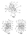
- Fig. 1
- einen schematischen axialen Längsschnitt eines Futters für drehantreibbare Werkzeuge, bei dem eine innere Verriegelungseinrichtung für eine Schrumpfhülse sich in ihrer Verriegelungsstellung befindet,
- Fig. 2
- eine schematische Seitenansicht mit teilweisem Schnitt entlang der Linie II - II in
Fig. 1 , - Fig. 3
- einen schematischen Schnitt entlang der Linie III - III in
Fig.1 , - Fig. 4
- eine schematische perspektivische Ansicht eines von einem Rohr zentral durchsetzten, in Verriegelungsstellung dargestellten Riegels der Verriegelungseinrichtung des Futters in
Fig. 1 , - Fig. 5
- einen schematischen Schnitt entlang der Linie V - V, bei dem sich der Riegel in der Verriegelungsstellung befindet,
- Fig. 6
- einen schematischen Schnitt etwa entsprechend demjenigen in
Fig. 5 , wobei sich der Riegel in der Freigabestellung befindet. - In den Zeichnungen ist ein Futter 10 für drehantreibbare Werkzeuge gezeigt, insbesondere für Bohrer, vor allem für Gewindebohrer. Das Futter 10 ist z. B. mit einem Minimallängenausgleich mit axialer Dämpfung versehen, der etwaige Synchronisationsfehler beim Gewindeformen oder Gewindeschneiden mittels eines nicht gezeigten Gewindebohrers während der spangebenden Bearbeitung sowie etwaige maschinenseitig,z. B. beim Umschalten der Werkzeugmaschinenspindel, auftretende Axialkräfte kompensieren kann. Diese Wirkung ist durch integrierte, verformbare und nur schematisch angedeutete Ringe 11 aus einem Elastomer erreicht. Das Futter 10 weist eine Futterhülse 12 mit zentraler innerer Aufnahme 13 auf, wobei die Futterhülse 12 maschinenseitig aufnehmbar ist, und zwar entweder direkt oder in der Ausbildung als Einsatz, der dann maschinenseitig in einem dort vorhandenen, nicht gezeigten Futter gespannt und gehalten werden kann. Die Aufnahme 13 besteht z. B. aus einer zylindrischen Bohrung 14 am in
Fig. 1 vorderen rechten Ende der Futterhülse 12. In die Aufnahme 13 ist ein Einsatz 15 mit einem zylindrischen Einsteckteil 16 einsteckbar. Der Einsatz 15 kann in vorteilhafter Weise aus einer Schrumpfhülse 17 bestehen, die zur thermischen Schrumpfbefestigung eines Werkzeuges darin ausgebildet ist. Eine derartige Schrumpfhülse 17 zur thermischen Schrumpfbefestigung eines Werkzeuges muss zum Werkzeugwechsel erwärmt werden, um eine das Werkzeug freigebende Dehnung zu erzeugen. Um bei dieser Erwärmung die Ringe 11 aus einem Elastomer nicht zu beschädigen, muss die Schrumpfhülse 17 zum Werkzeugwechsel aus der Futterhülse 12 entnehmbar sein. Im eingesteckten Zustand der Schrumpfhülse 17 ist diese mit der Futterhülse 12 mittels einer Verriegelungseinrichtung 30 lösbar verbunden, die sich bei den Darstellungen inFig. 1, 2 ,4 und 5 in einer Verriegelungsstellung befindet, in der die eingesteckte Schrumpfhülse 17 in der Aufnahme 13 der Futterhülse 12 fest verriegelt ist. Die Verriegelungseinrichtung 30 lässt sich aus dieser Verriegelungsstellung in eine inFig. 6 nur schematisch angedeutete Freigabestellung bewegen, in der die Schrumpfhülse 17 in der Aufnahme 13 gelöst und aus dieser gegensinnig zum Einstecken herausziehbar und entnehmbar ist. - Die Futterhülse 12 und die Schrumpfhülse 17 sind für Minimalmengenschmierung mit zentraler Zuführung von Kühl-/Schmiermittel über ein zentrales Rohr 18 zumindest bis in die Schrumpfhülse 17 hinein ausgebildet. Die Verriegelungseinrichtung 30 ist derart gestaltet, dass die Schrumpfhülse 17 bei in der Futterhülse 12 verbleibendem Rohr 18 in der Aufnahme 13 lösbar und aus dieser entnehmbar ist. Bei dieser Entnahme der Schrumpfhülse 17 verbleibt somit das Rohr 18 innerhalb der Futterhülse 12 in der in
Fig. 1 dargestellten Position, wobei das Rohr 18 durch die Verriegelungseinrichtung 30 noch geführt ist, wie später noch erläutert wird. Bei der Minimalmengenschmierung wird ein Aerosol, das aus in Luft fein verteilten Schmierstofftröpfchen besteht, durch einen Kanal, der im Inneren des Rohres 18 gebildet ist und einen konstanten Querschnitt aufweist, hindurch möglichst bis zu den Schneiden eines eingesetzten Werkzeuges geleitet. Das zentral angeordnete Rohr 18 weist über die gesamte Länge des dadurch gebildeten Kühl-/Schmiermittelkanals einen konstanten Querschnitt ohne etwaige Umlenkungen, Abkantungen od. dgl. auf, um zu verhindern, dass sich an derartigen Querschnittsänderungen die feinen Schmierstofftröpfchen absetzen können, wodurch eine zuverlässige Minimalmengenschmierung beeinträchtigt wäre. Diesen Bedingungen ist durch das zentrale geradlinig verlaufende Rohr 18 im Zentrum der Futterhülse 12 und der Aufnahme 13 Rechnung getragen, wobei das Rohr 18 sich bis zur Schrumpfhülse 17 und in dieser durch einen zentralen Durchlass 19 zumindest im Bereich des Einsteckteils 16 erstreckt. Die Schrumpfhülse 17 enthält eine zentrale, mittels eines Gewindes 20 axial einstellbare Einstellhülse 21, die der axialen Einstellung in Anpassung an das in die Schrumpfhülse 17 eingesetzte Werkzeug dient, wobei der zentrale Durchlass 19 für das Rohr 18 in dieser Einsteckhülse 21 enthalten ist. - Die Verriegelungseinrichtung 30 enthält in der Futterhülse 12 einen Riegel 31, der in der Futterhülse 12 zwischen einer Verriegelungsstellung gemäß
Fig. 1, 2 ,4 und 5 und einer Freigabestellung gemäßFig. 6 bewegbar ist. Der Riegel 31 dient in seiner Verriegelungsstellung der Verriegelung der in die Aufnahme 13 eingesteckten Schrumpfhülse 17. Die Bewegung des Riegels 31 zwischen dieser Verriegelungsstellung und der Freigabestellung, in der die Schrumpfhülse 17 aus der Aufnahme 13 entnommen werden kann, wird durch den Axialverlauf des Rohres 18, das fester Bestandteil der Futterhülse 12 ist und bleibt, nicht behindert. Der Riegel 31 reicht quer durch die Aufnahme 13 und ist um seine Längsmittelachse 32 zwischen der Verriegelungsstellung und der Freigabestellung drehverstellbar. Hierzu dient eine an einem, inFig. 1 unten befindlichen Ende des Riegels 31 vorgesehene Werkzeugangriffsfläche, z. B. ein Innensechskant 33, in den ein Werkzeug eingesteckt werden kann, das danach zur Drehverstellung z. B. um zumindest etwa 90° im Uhrzeigersinn gemäß Pfeil 34 inFig. 4 gedreht werden kann. Der Riegel 31 enthält einen zur Längsmittelachse 22 der Aufnahme 13 koaxialen, zu seiner Längsmittelachse 32 quer gerichteten ersten Durchlass 35 in Form einer Bohrung, durch den sich das Rohr 18 hindurch erstreckt. Der Bohrungsdurchmesser ist zumindest geringfügig größer als der Außendurchmesser des Rohres 18. Ferner enthält der Riegel 31 einen zweiten Durchlass 36 etwa gleichen Durchmessers, der etwa rechtwinklig zum ersten Durchlass 35 gerichtet ist und diesen kreuzt, so dass beide Durchlässe 35, 36 im Zentrum ineinander übergehen. Die Längsmittelachsen beider Durchlässe 35 und 36 verlaufen innerhalb einer gemeinsamen, quer zur Längsmittelachse 32 des Riegels 31 gerichteten Radialebene. Zwei einander diamentral gegenüberliegende, inFig. 5 und 6 der besseren Übersicht wegen mit 37 und 38 gekennzeichnete, Quadrantenbereiche zwischen den beiden sich kreuzenden Durchlässen sind entfernt, derart, dass eine Drehverstellung des Riegels 31 in Pfeilrichtung 34 um einen Winkel von zumindest etwa 90° relativ zu dem hindurchführenden und feststehenden Rohr 18 möglich ist. - Der Riegel 31 ist aus einem in der Futterhülse 12 um die Längsmittelachse 32 drehbar gelagerten Zylinderbolzen gebildet, der auf zwei einander diametral gegenüberliegenden Umfangsbereichen Abflachungen 39 und 40 aufweist, die zueinander etwa parallel verlaufen und sich parallel zur Längsmittelachse 32 des Riegels 31 erstrecken. Der erste Durchlass 35 mündet beidendig in den Abflachungen 39, 40 und ist mit seiner Mittelachse zu diesen etwa rechtwinklig ausgerichtet.
- Die Schrumpfhülse 17 weist am Einsteckteil 16 eine endseitige Gabel 23 auf, die in
Fig. 1 nach links hin offen ist und durch zwei zueinander parallele Gabelschenkel 24 und 25 gebildet ist. Beim Einstecken der Schrumpfhülse 17 in die Aufnahme 13 der Futterhülse 12 kann die Gabel 23 mit ihren Gabelschenkeln 24, 25 den sich in Freigabestellung befindlichen Riegel 31 übergreifen und zwischen den Gabelschenkeln 24, 25 aufnehmen. Die Gabel 23 ist mit einer dem Durchmesser des Riegels 31 zumindest im wesentlichen entsprechenden und in Richtung der Längsmittelachse 32 verlaufenden Bohrung dergestalt versehen, dass die Gabeln 24, 25 auf den einander zugewandten Seiten entsprechende, an die Zylinderform des Riegels 31 angepasste Eintiefungen 26 bzw. 27, z. B. konkave Bogenverläufe, aufweisen, in die der Riegel 31 in Form des Zylinderbolzens bei der Drehung um seine Längsmittelachse 32 in seine Verriegelungsstellung (Fig. 5 ) mit seinen bogenförmigen Umfangsbereichen, die zwischen den Abflachungen 39, 40 verlaufen, zur Verriegelung der Schrumpfhülse 17 formschlüssig hineindrehbar ist. - Der Riegel 31 ist mit in
Fig. 3 gezeigten Rastelementen 41, 42 und 43 ausgestattet, die z. B. aus Kugeln bestehen. Zwei Rastelemente 41, 42 sind in einer diametralen Bohrung 44 in einer Kopfscheibe 45 des Riegels 31 enthalten. In der Bohrung 44 befindet sich eine Feder 46, mittels der die Rastelemente 41 und 42 mit einer radial nach außen gerichteten Federkraft beaufschlagt und gegen die Futterhülse 12 angedrückt sind. Die Futterhülse 12 enthält auf der Höhe der Rastelemente 41 bis 43 innenseitig eine über etwa 90° Umfangswinkel sich erstreckende Nut 47, in die die Rastelemente radial eingreifen. Das Rastelement 43 sitzt in einer Vertiefung 48 der Kopfscheibe 45. Die beiden Drehpositionen des Riegels 31, die der Verriegelungsstellung bzw. Freigabestellung entsprechen, werden durch die Rastelemente 41 bis 43 definiert, die in der Nut 47 gleiten und an der jeweiligen, radial gerichteten Endwand der Nut 47 anschlagen. Die Verriegelung des Riegels 31 in der Verriegelungsstellung erfolgt über das Rastelement 43 und das angefederte Rastelement 41 und in der Freigabestellung über das Rastelement 43 und das angefederte Rastelement 42. - Die Futterhülse 12 ist im Bereich des Riegels 31 von einer Hülse 28 umgeben, die im Bereich des Innensechskants 33 mit einer Bohrung 29 für den Durchgriff eines Werkzeuges versehen ist.
- In
Fig. 1, 2 ,4 und 5 ist der Zustand gezeigt, bei dem in die Aufnahme 13 der Futterhülse 12 eine Schrumpfhülse 17 mit ihrem Einsteckteil 16 eingesteckt und mittels der Verriegelungseinrichtung 30, die sich in ihrer Verriegelungsstellung befindet, so verriegelt ist, dass ein sicherer axialer Halt gewährleistet ist. Durch die Passung zwischen der Bohrung 14 und dem Durchmesser des Einsteckteils 16 ist zugleich eine spielfreie, sichere Befestigung in radialer Richtung gewährleistet. Eine zuverlässige Drehmomentübertragung ist auch mittels des zwischen die Gabelschenkel 24, 25 formschlüssig eingreifenden Riegels 31 gewährleistet. Ferner ist eine große Rundlaufgenauigkeit sichergestellt. Die Verriegelung der Schrumpfhülse 17 ist dadurch sichergestellt, dass der Riegel 31 in der Verriegelungsstellung gemäßFig. 1, 2 ,4 und 5 mit den beiden einander diametral gegenüberliegenden, zwischen den Abflachungen 39 und 40 befindlichen Umfangsbereichen formschlüssig aufgenommen ist in den Eintiefungen 26, 27 der Gabelschenkel 24, 25. Die Verriegelungsstellung ist durch die Rastelemente 41 und 43 gesichert, die beide in die Nut 47 eingreifen und dort in jeder Drehrichtung an der zugeordneten Endwand der Nut 47 anschlagen. - Soll die Schrumpfhülse 17 mit darin eingeschrumpftem, nicht gezeigtem Werkzeug in der Aufnahme 13 gelöst werden, so wird der Riegel 31 mittels eines durch die Bohrung 29 in den Innensechskant 33 eingesteckten Werkzeuges in Richtung des Pfeiles 34 um etwa 90°-Umfangswinkel gedreht, d. h. von der in
Fig. 5 gezeigten Verriegelungsstellung in die inFig. 6 gezeigte Freigabestellung. In dieser sind die Eintiefungen 26, 27 der Gabelschenkel 24, 25 außer Eingriff mit den zwischen den Abflachungen 39, 40 verlaufenden bogenförmigen Umfangsbereichen des Riegels 31. Das von Abflachung 39 zu Abflachung 40 gemessene Querschnittsmaß ist kleiner als das Öffnungsmaß der Gabel 23 in Form des Querabstandes der beiden Gabelschenkel 24, 25 voneinander, so dass in dieser Freigabestellung gemäßFig. 6 die Schrumpfhülse 17 nicht mehr verriegelt ist und somit aus der Aufnahme 13 der Futterhülse 12 herausgezogen werden kann. Bei der Drehbetätigung des Riegels 31 von der Verriegelungsstellung in die Freigabestellung verbleibt das Rohr 18 fest an der Futterhülse 12 und durchsetzt den Riegel 31, und zwar in der Verriegelungsstellung aufgrund des Durchgangs durch den ersten Durchlass 35 und in der demgegenüber um etwa 90° gedrehten Freigabestellung durch den Durchgang durch den zweiten Durchlass 36. Aufgrund der schematisch angedeuteten Schlitze in den beiden Quadrantenbereichen 37 und 38, über die die beiden Durchlässe 35, 36 in Umfangsrichtung miteinander verbunden sind, wird relativ zum feststehenden Rohr 18 diese Drehbetätigung des Riegels 31 zwischen der Verriegelungsstellung und der Freigabestellung möglich, ohne dass dabei das in der Futterhülse 12 verbleibende Rohr 18 störend im Wege ist. Die Gestaltung macht es somit möglich, ein für optimale Minimalmengenschmierung erforderliches geradliniges Rohr 18 im Zentrum der Futterhülse 12 und der Schrumpfhülse 17 zu platzieren und gleichwohl eine Verriegelung und Entriegelung der eingesteckten Schrumpfhülse 17 vorzunehmen, ohne dass dabei das Rohr 18 störend im Wege ist. Zugleich ist nach Entriegeln der Schrumpfhülse 17 auch ein Herausziehen dieser aus der Aufnahme 13 schnell und einfach bei nach wie vor verbleibendem Rohr 18 möglich. Das Futter 10 ermöglicht somit ein einfaches und schnelles Wechseln des Einsatzes 15, insbesondere in Form der Schrumpfhülse 17, ohne dass dabei das Rohr 18 entfernt werden müsste oder in sonstiger Weise störend im Wege ist. Bei allem ergibt sich für das Futter 10 eine schlanke, kompakte Bauform. Dabei versteht es sich, dass als Einsatz 15 statt der Schrumpfhülse 17 auch andere schnelladaptierbare Einsätze verwendet werden können. Ebenso versteht es sich, dass die Futterhülse 12 als maschinenseitig in einem dort vorhandenen Futter aufnehmbarer Einsatz ausgebildet sein kann oder statt dessen direkt maschinenseitig aufnehmbar ist.
Claims (12)
- Futter für drehantreibbare Werkzeuge, insbesondere Bohrer, Gewindebohrer od. dgl., mit einer maschinenseitig aufnehmbaren Futterhülse (12), die eine zentrale innere Aufnahme (13) für einen in die Aufnahme (13) einsteckbaren Einsatz (15) enthält, der z. B. als Schrumpfhülse (17) zur thermischen Schrumpfbefestigung eines Werkzeuges darin ausgebildet ist und der im eingesteckten Zustand mit der Futterhülse (12) mittels einer Verriegelungseinrichtung (30) lösbar verbindbar ist, wobei die Futterhülse (12) und der Einsatz (15), insbesondere die Schrumpfhülse (17), für Minimalmengenschmierung mit zentraler Zuführung von Kühl-/Schmiermittel über ein zentrales Rohr (18) zumindest bis in den Einsatz (15) hinein ausgebildet sind und die Verriegelungseinrichtung (30) derart gestaltet ist, dass der Einsatz (15) bei in der Futterhülse (12) verbleibendem Rohr (18) in der Aufnahme (13) lösbar und daraus entnehmbar ist,
dadurch gekennzeichnet,
dass die Verriegelungseinrichtung (30) in der Futterhülse (12) einen quer durch die Aufnahme (13) reichenden und um seine Längsmittelachse (32) zwischen einer Verriegelungsstellung und einer Freigabestellung um etwa 90° Umfangswinkel drehverstellbaren Riegel (31) für eine Verriegelung des in die Aufnahme (13) eingesteckten Einsatzes (15) enthält und dass die Bewegung des Riegels (31) zwischen der Verriegelungsstellung und Freigabestellung nicht durch den Axialverlauf des Rohres behindert ist. - Futter nach Anspruch 1,
dadurch gekennzeichnet,
dass der Einsatz (15) einen zentralen Durchlass (19) für das Rohr (18) enthält. - Futter nach Anspruch 2,
dadurch gekennzeichnet,
dass der Einsatz (15) eine zentrale, mittels eines Gewindes (20) axial einstellbare Einstellhülse (21) enthält und dass der zentrale Durchlass (19) für das Rohr (18) in der Einstellhülse (21) enthalten ist. - Futter nach Anspruch 1,
dadurch gekennzeichnet,
dass der Riegel (31) einen zur Längsmittelachse (22) der Aufnahme (13) koaxialen, quer zu seiner Längsmittelachse (32) gerichteten Durchlass (35) enthält, durch den sich das Rohr (18) hindurcherstreckt. - Futter nach Anspruch 4,
dadurch gekennzeichnet,
dass der Riegel (31) einen zweiten Durchlass (36) enthält, der etwa rechtwinklig zum ersten Durchlass (35) gerichtet ist und diesen kreuzt, und
dass zwei einander etwa diametral gegenüberliegende Quadrantenbereiche (37, 38) zwischen den beiden sich kreuzenden Durchlässen (35, 36) entfernt sind, derart, dass eine Drehverstellung des Riegels (31) um den Winkel von etwa 90° relativ zu dem hindurchführenden Rohr (18) möglich ist. - Futter nach einem der Ansprüche 1 bis 5,
dadurch gekennzeichnet,
dass der Riegel (31) mittels Rastelementen (41, 42, 43), z. B. Rastkugeln, bei der Drehverstellung in der Verriegelungsstellung sowie in der Freigabestellung verrastbar ist. - Futter nach einem der Ansprüche 1 bis 6,
dadurch gekennzeichnet,
dass der Riegel (31) aus einem in der Futterhülse (12) drehbar gelagerten Zylinderbolzen gebildet ist. - Futter nach einem der Ansprüche 1 bis 7,
dadurch gekennzeichnet,
dass der Riegel (31), insbesondere Zylinderbolzen, auf zwei einander diametral gegenüberliegenden Umfangsbereichen Abflachungen (39, 40) aufweist, die zur Längsmittelachse (32) und zueinander etwa parallel verlaufen. - Futter nach einem der Ansprüche 4 bis 8,
dadurch gekennzeichnet,
dass die beiden zueinander etwa rechtwinkligen Durchlässe (35, 36) im Riegel (31) als Bohrungen ausgebildet sind. - Futter nach Anspruch 8 oder 9,
dadurch gekennzeichnet,
dass ein Durchlass (35), insbesondere eine Bohrung, im Riegel (31) mit seiner Mittelachse etwa rechtwinklig zu den beiden Abflachungen (39, 40) ausgerichtet ist. - Futter nach einem der Ansprüche 1 bis10,
dadurch gekennzeichnet,
dass der Einsatz (15) an seinem Einsteckende (16) eine Gabel (23) aufweist, die beim Einstecken des Einsatzes (15) in die Aufnahme (13) der Futterhülse (12) den Riegel (31), wenn sich dieser in seiner Freigabestellung befindet, übergreifen und zwischen ihren Gabelschenkeln (24, 25) aufnehmen kann. - Futter nach Anspruch 11,
dadurch gekennzeichnet,
dass die Gabel (23) auf den einander zugewandten Seiten der Gabelschenkel (24, 25) an den als Zylinderbolzen ausgebildeten Riegel (31) angepasste Eintiefungen (26, 27), z. B. konkave Bogenverläufe, aufweist, in die der als Zylinderbolzen ausgebildete Riegel (31) bei Drehung in seine Verriegelungsstellung mit seinen zwischen den Abflachungen (39, 40) verlaufenden bogenförmigen Umfangsbereichen zur Verriegelung des Einsatzes (15) formschlüssig hineindrehbar ist.
Applications Claiming Priority (1)
| Application Number | Priority Date | Filing Date | Title |
|---|---|---|---|
| DE102006002089A DE102006002089A1 (de) | 2006-01-17 | 2006-01-17 | Futter für drehantreibbare Werkzeuge |
Publications (3)
| Publication Number | Publication Date |
|---|---|
| EP1808246A2 EP1808246A2 (de) | 2007-07-18 |
| EP1808246A3 EP1808246A3 (de) | 2008-08-27 |
| EP1808246B1 true EP1808246B1 (de) | 2010-02-17 |
Family
ID=38048004
Family Applications (1)
| Application Number | Title | Priority Date | Filing Date |
|---|---|---|---|
| EP06024977A Not-in-force EP1808246B1 (de) | 2006-01-17 | 2006-12-02 | Futter für drehantreibbare Werkzeuge |
Country Status (4)
| Country | Link |
|---|---|
| EP (1) | EP1808246B1 (de) |
| AT (1) | ATE457843T1 (de) |
| DE (2) | DE102006002089A1 (de) |
| ES (1) | ES2341477T3 (de) |
Families Citing this family (1)
| Publication number | Priority date | Publication date | Assignee | Title |
|---|---|---|---|---|
| DE202014104802U1 (de) * | 2014-10-07 | 2016-01-11 | Bilz Werkzeugfabrik Gmbh & Co. Kg | Werkzeughalter mit Fluidzufuhr |
Family Cites Families (3)
| Publication number | Priority date | Publication date | Assignee | Title |
|---|---|---|---|---|
| DE4128446C1 (en) * | 1991-08-28 | 1992-08-13 | Mercedes-Benz Aktiengesellschaft, 7000 Stuttgart, De | Standard stem for rotary machining tools - has outer, precise fitting cylinder for setting into retaining aperture in spindle |
| DE4232790C1 (de) * | 1992-09-30 | 1994-02-10 | Daimler Benz Ag | Standardschaft für rotierende Bearbeitungswerkzeuge zur unmittelbaren Aufnahme in eine Arbeitsspindel einer Werkzeugmaschine |
| JP3849096B2 (ja) * | 2002-07-18 | 2006-11-22 | ホーコス株式会社 | 工作機械の工具ホルダ |
-
2006
- 2006-01-17 DE DE102006002089A patent/DE102006002089A1/de not_active Withdrawn
- 2006-12-02 ES ES06024977T patent/ES2341477T3/es active Active
- 2006-12-02 AT AT06024977T patent/ATE457843T1/de active
- 2006-12-02 DE DE502006006163T patent/DE502006006163D1/de active Active
- 2006-12-02 EP EP06024977A patent/EP1808246B1/de not_active Not-in-force
Also Published As
| Publication number | Publication date |
|---|---|
| ATE457843T1 (de) | 2010-03-15 |
| DE502006006163D1 (de) | 2010-04-01 |
| EP1808246A2 (de) | 2007-07-18 |
| DE102006002089A1 (de) | 2007-07-19 |
| ES2341477T3 (es) | 2010-06-21 |
| EP1808246A3 (de) | 2008-08-27 |
Similar Documents
| Publication | Publication Date | Title |
|---|---|---|
| EP1504836B1 (de) | Schnellspannbohrfutter | |
| EP2318166B1 (de) | Werkzeug für spanende bearbeitung eines werkstücks | |
| DE102013103937B4 (de) | Schnellwechselsystem für eine Werkzeugaufnahme | |
| DE102013209371B4 (de) | Kupplungsteil, insbesondere Schneidkopf für ein Rotationswerkzeug sowie hierzu komplementäres Kupplungsteil und Rotationswerkzeug | |
| EP2370222B1 (de) | Werkzeugaufnahme | |
| EP1464426B1 (de) | Schnellspannfutter | |
| EP2755786A1 (de) | Spannsystem sowie grundkörper, spannzange und rotationswerkzeug dafür und ein installationsverfahren für das rotationswerkzeug im spannsystem | |
| DE102009059707B4 (de) | Vorrichtung zum Gewindewirbeln und Werkzeug zur Montage eines Wirbelrings | |
| DE102010006918B4 (de) | Verbindungssystem zum lösbaren Verbinden zweier Bauteile | |
| DE102009044994B4 (de) | Schneidwerkzeug mit austauschbarem Schneideinsatz, Schneideinsatzträger, Verfahren zum Befestigen eines austauschbaren Schneideinsatzes, Verfahren zum Austauschen eines Schneideinsatzes | |
| DE102009044995B4 (de) | Schneideinsatzträger, Schneideinsatzund drehangetriebenes Schneidwerkzeug | |
| DE102011116572B4 (de) | Spannvorrichtung und Werkzeughalter mit einer derartigen Spannvorrichtung | |
| EP1808246B1 (de) | Futter für drehantreibbare Werkzeuge | |
| DE3532842A1 (de) | Fraes- und/oder bohrmaschine | |
| DE102019100072A1 (de) | Ausziehbare Spannvorrichtung und Spanneinheit mit einer solchen Spannvorrichtung | |
| EP3890910B1 (de) | Bohrkopf zum auskesseln von nicht-zylindrischen innenkonturen | |
| DE202009014717U1 (de) | Schnellwechsel-Spannzeug für Bohrwerkzeuge mit Spannfläche | |
| DE9104377U1 (de) | Spannfutter für Schäfte | |
| WO1999024200A1 (de) | Schnellwechselanschluss für diamant-bohrmaschinenwerkzeuge, insbesondere für kernbohrmaschinenwerkzeuge (bohrkronenschnellverschluss) | |
| DE102023200289B4 (de) | Vorrichtung, welche ein Rotationswerkzeug aufweist, und Verfahren zum Befestigen oder Lösen eines Schneideinsatzes bei einer solchen Vorrichtung | |
| DE20317695U1 (de) | Bohrvorrichtung | |
| DE102022118797B3 (de) | Bohranschlag | |
| WO1991008072A2 (de) | Klemmsystem zum dreh- und rundlaufsicheren verbinden von teilen, insbesondere werkzeugteilen | |
| DE8605002U1 (de) | Schnellwechselfutter für Werkzeuge | |
| DE2701337A1 (de) | Werkzeughalter |
Legal Events
| Date | Code | Title | Description |
|---|---|---|---|
| PUAI | Public reference made under article 153(3) epc to a published international application that has entered the european phase |
Free format text: ORIGINAL CODE: 0009012 |
|
| AK | Designated contracting states |
Kind code of ref document: A2 Designated state(s): AT BE BG CH CY CZ DE DK EE ES FI FR GB GR HU IE IS IT LI LT LU LV MC NL PL PT RO SE SI SK TR |
|
| AX | Request for extension of the european patent |
Extension state: AL BA HR MK YU |
|
| PUAL | Search report despatched |
Free format text: ORIGINAL CODE: 0009013 |
|
| AK | Designated contracting states |
Kind code of ref document: A3 Designated state(s): AT BE BG CH CY CZ DE DK EE ES FI FR GB GR HU IE IS IT LI LT LU LV MC NL PL PT RO SE SI SK TR |
|
| AX | Request for extension of the european patent |
Extension state: AL BA HR MK RS |
|
| 17P | Request for examination filed |
Effective date: 20080903 |
|
| 17Q | First examination report despatched |
Effective date: 20081106 |
|
| AKX | Designation fees paid |
Designated state(s): AT BE BG CH CY CZ DE DK EE ES FI FR GB GR HU IE IS IT LI LT LU LV MC NL PL PT RO SE SI SK TR |
|
| GRAP | Despatch of communication of intention to grant a patent |
Free format text: ORIGINAL CODE: EPIDOSNIGR1 |
|
| GRAS | Grant fee paid |
Free format text: ORIGINAL CODE: EPIDOSNIGR3 |
|
| GRAA | (expected) grant |
Free format text: ORIGINAL CODE: 0009210 |
|
| AK | Designated contracting states |
Kind code of ref document: B1 Designated state(s): AT BE BG CH CY CZ DE DK EE ES FI FR GB GR HU IE IS IT LI LT LU LV MC NL PL PT RO SE SI SK TR |
|
| REG | Reference to a national code |
Ref country code: GB Ref legal event code: FG4D Free format text: NOT ENGLISH |
|
| REG | Reference to a national code |
Ref country code: CH Ref legal event code: EP |
|
| REG | Reference to a national code |
Ref country code: IE Ref legal event code: FG4D Free format text: LANGUAGE OF EP DOCUMENT: GERMAN |
|
| REF | Corresponds to: |
Ref document number: 502006006163 Country of ref document: DE Date of ref document: 20100401 Kind code of ref document: P |
|
| REG | Reference to a national code |
Ref country code: SE Ref legal event code: TRGR |
|
| REG | Reference to a national code |
Ref country code: ES Ref legal event code: FG2A Ref document number: 2341477 Country of ref document: ES Kind code of ref document: T3 |
|
| REG | Reference to a national code |
Ref country code: NL Ref legal event code: VDEP Effective date: 20100217 |
|
| LTIE | Lt: invalidation of european patent or patent extension |
Effective date: 20100217 |
|
| PG25 | Lapsed in a contracting state [announced via postgrant information from national office to epo] |
Ref country code: PT Free format text: LAPSE BECAUSE OF FAILURE TO SUBMIT A TRANSLATION OF THE DESCRIPTION OR TO PAY THE FEE WITHIN THE PRESCRIBED TIME-LIMIT Effective date: 20100617 Ref country code: LT Free format text: LAPSE BECAUSE OF FAILURE TO SUBMIT A TRANSLATION OF THE DESCRIPTION OR TO PAY THE FEE WITHIN THE PRESCRIBED TIME-LIMIT Effective date: 20100217 Ref country code: IS Free format text: LAPSE BECAUSE OF FAILURE TO SUBMIT A TRANSLATION OF THE DESCRIPTION OR TO PAY THE FEE WITHIN THE PRESCRIBED TIME-LIMIT Effective date: 20100617 |
|
| PG25 | Lapsed in a contracting state [announced via postgrant information from national office to epo] |
Ref country code: SI Free format text: LAPSE BECAUSE OF FAILURE TO SUBMIT A TRANSLATION OF THE DESCRIPTION OR TO PAY THE FEE WITHIN THE PRESCRIBED TIME-LIMIT Effective date: 20100217 Ref country code: PL Free format text: LAPSE BECAUSE OF FAILURE TO SUBMIT A TRANSLATION OF THE DESCRIPTION OR TO PAY THE FEE WITHIN THE PRESCRIBED TIME-LIMIT Effective date: 20100217 Ref country code: LV Free format text: LAPSE BECAUSE OF FAILURE TO SUBMIT A TRANSLATION OF THE DESCRIPTION OR TO PAY THE FEE WITHIN THE PRESCRIBED TIME-LIMIT Effective date: 20100217 Ref country code: FI Free format text: LAPSE BECAUSE OF FAILURE TO SUBMIT A TRANSLATION OF THE DESCRIPTION OR TO PAY THE FEE WITHIN THE PRESCRIBED TIME-LIMIT Effective date: 20100217 |
|
| REG | Reference to a national code |
Ref country code: IE Ref legal event code: FD4D |
|
| PG25 | Lapsed in a contracting state [announced via postgrant information from national office to epo] |
Ref country code: EE Free format text: LAPSE BECAUSE OF FAILURE TO SUBMIT A TRANSLATION OF THE DESCRIPTION OR TO PAY THE FEE WITHIN THE PRESCRIBED TIME-LIMIT Effective date: 20100217 Ref country code: RO Free format text: LAPSE BECAUSE OF FAILURE TO SUBMIT A TRANSLATION OF THE DESCRIPTION OR TO PAY THE FEE WITHIN THE PRESCRIBED TIME-LIMIT Effective date: 20100217 Ref country code: CY Free format text: LAPSE BECAUSE OF FAILURE TO SUBMIT A TRANSLATION OF THE DESCRIPTION OR TO PAY THE FEE WITHIN THE PRESCRIBED TIME-LIMIT Effective date: 20100217 Ref country code: GR Free format text: LAPSE BECAUSE OF FAILURE TO SUBMIT A TRANSLATION OF THE DESCRIPTION OR TO PAY THE FEE WITHIN THE PRESCRIBED TIME-LIMIT Effective date: 20100518 Ref country code: IE Free format text: LAPSE BECAUSE OF FAILURE TO SUBMIT A TRANSLATION OF THE DESCRIPTION OR TO PAY THE FEE WITHIN THE PRESCRIBED TIME-LIMIT Effective date: 20100217 Ref country code: NL Free format text: LAPSE BECAUSE OF FAILURE TO SUBMIT A TRANSLATION OF THE DESCRIPTION OR TO PAY THE FEE WITHIN THE PRESCRIBED TIME-LIMIT Effective date: 20100217 |
|
| PG25 | Lapsed in a contracting state [announced via postgrant information from national office to epo] |
Ref country code: SK Free format text: LAPSE BECAUSE OF FAILURE TO SUBMIT A TRANSLATION OF THE DESCRIPTION OR TO PAY THE FEE WITHIN THE PRESCRIBED TIME-LIMIT Effective date: 20100217 Ref country code: CZ Free format text: LAPSE BECAUSE OF FAILURE TO SUBMIT A TRANSLATION OF THE DESCRIPTION OR TO PAY THE FEE WITHIN THE PRESCRIBED TIME-LIMIT Effective date: 20100217 Ref country code: BG Free format text: LAPSE BECAUSE OF FAILURE TO SUBMIT A TRANSLATION OF THE DESCRIPTION OR TO PAY THE FEE WITHIN THE PRESCRIBED TIME-LIMIT Effective date: 20100517 |
|
| PLBE | No opposition filed within time limit |
Free format text: ORIGINAL CODE: 0009261 |
|
| STAA | Information on the status of an ep patent application or granted ep patent |
Free format text: STATUS: NO OPPOSITION FILED WITHIN TIME LIMIT |
|
| 26N | No opposition filed |
Effective date: 20101118 |
|
| PG25 | Lapsed in a contracting state [announced via postgrant information from national office to epo] |
Ref country code: DK Free format text: LAPSE BECAUSE OF FAILURE TO SUBMIT A TRANSLATION OF THE DESCRIPTION OR TO PAY THE FEE WITHIN THE PRESCRIBED TIME-LIMIT Effective date: 20100217 |
|
| BERE | Be: lapsed |
Owner name: BILZ WERKZEUGFABRIK G.M.B.H. & CO. KG Effective date: 20101231 |
|
| PG25 | Lapsed in a contracting state [announced via postgrant information from national office to epo] |
Ref country code: MC Free format text: LAPSE BECAUSE OF NON-PAYMENT OF DUE FEES Effective date: 20101231 |
|
| REG | Reference to a national code |
Ref country code: CH Ref legal event code: PL |
|
| PG25 | Lapsed in a contracting state [announced via postgrant information from national office to epo] |
Ref country code: BE Free format text: LAPSE BECAUSE OF NON-PAYMENT OF DUE FEES Effective date: 20101231 |
|
| PG25 | Lapsed in a contracting state [announced via postgrant information from national office to epo] |
Ref country code: LI Free format text: LAPSE BECAUSE OF NON-PAYMENT OF DUE FEES Effective date: 20101231 Ref country code: CH Free format text: LAPSE BECAUSE OF NON-PAYMENT OF DUE FEES Effective date: 20101231 |
|
| PG25 | Lapsed in a contracting state [announced via postgrant information from national office to epo] |
Ref country code: LU Free format text: LAPSE BECAUSE OF NON-PAYMENT OF DUE FEES Effective date: 20101202 Ref country code: HU Free format text: LAPSE BECAUSE OF FAILURE TO SUBMIT A TRANSLATION OF THE DESCRIPTION OR TO PAY THE FEE WITHIN THE PRESCRIBED TIME-LIMIT Effective date: 20100818 |
|
| PG25 | Lapsed in a contracting state [announced via postgrant information from national office to epo] |
Ref country code: TR Free format text: LAPSE BECAUSE OF FAILURE TO SUBMIT A TRANSLATION OF THE DESCRIPTION OR TO PAY THE FEE WITHIN THE PRESCRIBED TIME-LIMIT Effective date: 20100217 |
|
| REG | Reference to a national code |
Ref country code: DE Ref legal event code: R082 Ref document number: 502006006163 Country of ref document: DE Representative=s name: WITTE, WELLER & PARTNER, DE Ref country code: DE Ref legal event code: R082 Ref document number: 502006006163 Country of ref document: DE Representative=s name: WITTE, WELLER & PARTNER PATENTANWAELTE MBB, DE |
|
| REG | Reference to a national code |
Ref country code: FR Ref legal event code: PLFP Year of fee payment: 10 |
|
| PGFP | Annual fee paid to national office [announced via postgrant information from national office to epo] |
Ref country code: GB Payment date: 20151221 Year of fee payment: 10 |
|
| PGFP | Annual fee paid to national office [announced via postgrant information from national office to epo] |
Ref country code: SE Payment date: 20151221 Year of fee payment: 10 Ref country code: FR Payment date: 20151221 Year of fee payment: 10 Ref country code: ES Payment date: 20151214 Year of fee payment: 10 Ref country code: AT Payment date: 20151222 Year of fee payment: 10 |
|
| PGFP | Annual fee paid to national office [announced via postgrant information from national office to epo] |
Ref country code: IT Payment date: 20151228 Year of fee payment: 10 Ref country code: DE Payment date: 20160203 Year of fee payment: 10 |
|
| REG | Reference to a national code |
Ref country code: DE Ref legal event code: R119 Ref document number: 502006006163 Country of ref document: DE |
|
| REG | Reference to a national code |
Ref country code: SE Ref legal event code: EUG |
|
| REG | Reference to a national code |
Ref country code: AT Ref legal event code: MM01 Ref document number: 457843 Country of ref document: AT Kind code of ref document: T Effective date: 20161202 |
|
| GBPC | Gb: european patent ceased through non-payment of renewal fee |
Effective date: 20161202 |
|
| PG25 | Lapsed in a contracting state [announced via postgrant information from national office to epo] |
Ref country code: SE Free format text: LAPSE BECAUSE OF NON-PAYMENT OF DUE FEES Effective date: 20161203 |
|
| REG | Reference to a national code |
Ref country code: FR Ref legal event code: ST Effective date: 20170831 |
|
| PG25 | Lapsed in a contracting state [announced via postgrant information from national office to epo] |
Ref country code: AT Free format text: LAPSE BECAUSE OF NON-PAYMENT OF DUE FEES Effective date: 20161202 Ref country code: IT Free format text: LAPSE BECAUSE OF NON-PAYMENT OF DUE FEES Effective date: 20161202 Ref country code: FR Free format text: LAPSE BECAUSE OF NON-PAYMENT OF DUE FEES Effective date: 20170102 |
|
| PG25 | Lapsed in a contracting state [announced via postgrant information from national office to epo] |
Ref country code: DE Free format text: LAPSE BECAUSE OF NON-PAYMENT OF DUE FEES Effective date: 20170701 Ref country code: GB Free format text: LAPSE BECAUSE OF NON-PAYMENT OF DUE FEES Effective date: 20161202 |
|
| PG25 | Lapsed in a contracting state [announced via postgrant information from national office to epo] |
Ref country code: ES Free format text: LAPSE BECAUSE OF NON-PAYMENT OF DUE FEES Effective date: 20161203 |
|
| REG | Reference to a national code |
Ref country code: ES Ref legal event code: FD2A Effective date: 20181121 |