EP1808243B1 - Procede de production d'agglomere poreux, materiau de moulage d'agglomere poreux et agglomere poreux associe - Google Patents
Procede de production d'agglomere poreux, materiau de moulage d'agglomere poreux et agglomere poreux associe Download PDFInfo
- Publication number
- EP1808243B1 EP1808243B1 EP05793657.7A EP05793657A EP1808243B1 EP 1808243 B1 EP1808243 B1 EP 1808243B1 EP 05793657 A EP05793657 A EP 05793657A EP 1808243 B1 EP1808243 B1 EP 1808243B1
- Authority
- EP
- European Patent Office
- Prior art keywords
- temperature
- pore formation
- formation material
- draining
- binder
- Prior art date
- Legal status (The legal status is an assumption and is not a legal conclusion. Google has not performed a legal analysis and makes no representation as to the accuracy of the status listed.)
- Active
Links
- 238000000034 method Methods 0.000 title claims description 43
- 239000012778 molding material Substances 0.000 title 1
- 239000011148 porous material Substances 0.000 claims description 221
- 239000000463 material Substances 0.000 claims description 211
- 230000015572 biosynthetic process Effects 0.000 claims description 188
- 239000011230 binding agent Substances 0.000 claims description 124
- 238000005238 degreasing Methods 0.000 claims description 74
- 238000005245 sintering Methods 0.000 claims description 71
- 150000001875 compounds Chemical class 0.000 claims description 49
- 239000000843 powder Substances 0.000 claims description 26
- 238000004519 manufacturing process Methods 0.000 claims description 19
- 238000011049 filling Methods 0.000 claims description 12
- 239000008188 pellet Substances 0.000 claims description 11
- 238000001746 injection moulding Methods 0.000 claims description 10
- 238000002156 mixing Methods 0.000 claims description 7
- 238000010438 heat treatment Methods 0.000 claims description 2
- 239000000155 melt Substances 0.000 claims 1
- 239000002245 particle Substances 0.000 description 42
- 230000001965 increasing effect Effects 0.000 description 15
- 229910052751 metal Inorganic materials 0.000 description 15
- 239000002184 metal Substances 0.000 description 15
- 239000002923 metal particle Substances 0.000 description 11
- 238000000354 decomposition reaction Methods 0.000 description 10
- 239000000919 ceramic Substances 0.000 description 7
- 230000000052 comparative effect Effects 0.000 description 7
- 230000007423 decrease Effects 0.000 description 7
- 239000000203 mixture Substances 0.000 description 7
- 239000000126 substance Substances 0.000 description 7
- 239000004743 Polypropylene Substances 0.000 description 6
- 238000010586 diagram Methods 0.000 description 6
- 229920003229 poly(methyl methacrylate) Polymers 0.000 description 6
- 239000004926 polymethyl methacrylate Substances 0.000 description 6
- 229920006324 polyoxymethylene Polymers 0.000 description 6
- BASFCYQUMIYNBI-UHFFFAOYSA-N platinum Chemical compound [Pt] BASFCYQUMIYNBI-UHFFFAOYSA-N 0.000 description 4
- 239000003054 catalyst Substances 0.000 description 3
- 238000003754 machining Methods 0.000 description 3
- 229930182556 Polyacetal Natural products 0.000 description 2
- 239000004793 Polystyrene Substances 0.000 description 2
- 239000000470 constituent Substances 0.000 description 2
- 238000007796 conventional method Methods 0.000 description 2
- 238000009826 distribution Methods 0.000 description 2
- 238000002347 injection Methods 0.000 description 2
- 239000007924 injection Substances 0.000 description 2
- 230000014759 maintenance of location Effects 0.000 description 2
- 229910052697 platinum Inorganic materials 0.000 description 2
- -1 polypropylene Polymers 0.000 description 2
- 229920001155 polypropylene Polymers 0.000 description 2
- 229920002223 polystyrene Polymers 0.000 description 2
- 238000009834 vaporization Methods 0.000 description 2
- 230000008016 vaporization Effects 0.000 description 2
- GWEVSGVZZGPLCZ-UHFFFAOYSA-N Titan oxide Chemical compound O=[Ti]=O GWEVSGVZZGPLCZ-UHFFFAOYSA-N 0.000 description 1
- 229910052586 apatite Inorganic materials 0.000 description 1
- 238000005266 casting Methods 0.000 description 1
- 230000003197 catalytic effect Effects 0.000 description 1
- 238000006243 chemical reaction Methods 0.000 description 1
- 239000002131 composite material Substances 0.000 description 1
- 238000001816 cooling Methods 0.000 description 1
- 238000005520 cutting process Methods 0.000 description 1
- 230000003247 decreasing effect Effects 0.000 description 1
- 230000002708 enhancing effect Effects 0.000 description 1
- 239000000945 filler Substances 0.000 description 1
- 239000012530 fluid Substances 0.000 description 1
- 238000005187 foaming Methods 0.000 description 1
- 238000000227 grinding Methods 0.000 description 1
- 238000011068 loading method Methods 0.000 description 1
- 239000000314 lubricant Substances 0.000 description 1
- 239000008204 material by function Substances 0.000 description 1
- 238000005259 measurement Methods 0.000 description 1
- 238000010297 mechanical methods and process Methods 0.000 description 1
- 229910044991 metal oxide Inorganic materials 0.000 description 1
- 150000004706 metal oxides Chemical class 0.000 description 1
- 238000000465 moulding Methods 0.000 description 1
- 231100000252 nontoxic Toxicity 0.000 description 1
- 230000003000 nontoxic effect Effects 0.000 description 1
- VSIIXMUUUJUKCM-UHFFFAOYSA-D pentacalcium;fluoride;triphosphate Chemical compound [F-].[Ca+2].[Ca+2].[Ca+2].[Ca+2].[Ca+2].[O-]P([O-])([O-])=O.[O-]P([O-])([O-])=O.[O-]P([O-])([O-])=O VSIIXMUUUJUKCM-UHFFFAOYSA-D 0.000 description 1
- 238000007747 plating Methods 0.000 description 1
- 230000002028 premature Effects 0.000 description 1
- 230000002787 reinforcement Effects 0.000 description 1
- 239000011347 resin Substances 0.000 description 1
- 229920005989 resin Polymers 0.000 description 1
- 230000000717 retained effect Effects 0.000 description 1
- 230000000630 rising effect Effects 0.000 description 1
- 239000012798 spherical particle Substances 0.000 description 1
- OGIDPMRJRNCKJF-UHFFFAOYSA-N titanium oxide Inorganic materials [Ti]=O OGIDPMRJRNCKJF-UHFFFAOYSA-N 0.000 description 1
Images


Classifications
-
- B—PERFORMING OPERATIONS; TRANSPORTING
- B22—CASTING; POWDER METALLURGY
- B22F—WORKING METALLIC POWDER; MANUFACTURE OF ARTICLES FROM METALLIC POWDER; MAKING METALLIC POWDER; APPARATUS OR DEVICES SPECIALLY ADAPTED FOR METALLIC POWDER
- B22F3/00—Manufacture of workpieces or articles from metallic powder characterised by the manner of compacting or sintering; Apparatus specially adapted therefor ; Presses and furnaces
- B22F3/10—Sintering only
- B22F3/1017—Multiple heating or additional steps
- B22F3/1021—Removal of binder or filler
-
- B—PERFORMING OPERATIONS; TRANSPORTING
- B22—CASTING; POWDER METALLURGY
- B22F—WORKING METALLIC POWDER; MANUFACTURE OF ARTICLES FROM METALLIC POWDER; MAKING METALLIC POWDER; APPARATUS OR DEVICES SPECIALLY ADAPTED FOR METALLIC POWDER
- B22F3/00—Manufacture of workpieces or articles from metallic powder characterised by the manner of compacting or sintering; Apparatus specially adapted therefor ; Presses and furnaces
- B22F3/10—Sintering only
- B22F3/11—Making porous workpieces or articles
- B22F3/1121—Making porous workpieces or articles by using decomposable, meltable or sublimatable fillers
-
- C—CHEMISTRY; METALLURGY
- C04—CEMENTS; CONCRETE; ARTIFICIAL STONE; CERAMICS; REFRACTORIES
- C04B—LIME, MAGNESIA; SLAG; CEMENTS; COMPOSITIONS THEREOF, e.g. MORTARS, CONCRETE OR LIKE BUILDING MATERIALS; ARTIFICIAL STONE; CERAMICS; REFRACTORIES; TREATMENT OF NATURAL STONE
- C04B38/00—Porous mortars, concrete, artificial stone or ceramic ware; Preparation thereof
- C04B38/02—Porous mortars, concrete, artificial stone or ceramic ware; Preparation thereof by adding chemical blowing agents
-
- C—CHEMISTRY; METALLURGY
- C04—CEMENTS; CONCRETE; ARTIFICIAL STONE; CERAMICS; REFRACTORIES
- C04B—LIME, MAGNESIA; SLAG; CEMENTS; COMPOSITIONS THEREOF, e.g. MORTARS, CONCRETE OR LIKE BUILDING MATERIALS; ARTIFICIAL STONE; CERAMICS; REFRACTORIES; TREATMENT OF NATURAL STONE
- C04B38/00—Porous mortars, concrete, artificial stone or ceramic ware; Preparation thereof
- C04B38/04—Porous mortars, concrete, artificial stone or ceramic ware; Preparation thereof by dissolving-out added substances
-
- C—CHEMISTRY; METALLURGY
- C04—CEMENTS; CONCRETE; ARTIFICIAL STONE; CERAMICS; REFRACTORIES
- C04B—LIME, MAGNESIA; SLAG; CEMENTS; COMPOSITIONS THEREOF, e.g. MORTARS, CONCRETE OR LIKE BUILDING MATERIALS; ARTIFICIAL STONE; CERAMICS; REFRACTORIES; TREATMENT OF NATURAL STONE
- C04B38/00—Porous mortars, concrete, artificial stone or ceramic ware; Preparation thereof
- C04B38/06—Porous mortars, concrete, artificial stone or ceramic ware; Preparation thereof by burning-out added substances by burning natural expanding materials or by sublimating or melting out added substances
-
- B—PERFORMING OPERATIONS; TRANSPORTING
- B22—CASTING; POWDER METALLURGY
- B22F—WORKING METALLIC POWDER; MANUFACTURE OF ARTICLES FROM METALLIC POWDER; MAKING METALLIC POWDER; APPARATUS OR DEVICES SPECIALLY ADAPTED FOR METALLIC POWDER
- B22F2998/00—Supplementary information concerning processes or compositions relating to powder metallurgy
- B22F2998/10—Processes characterised by the sequence of their steps
-
- C—CHEMISTRY; METALLURGY
- C04—CEMENTS; CONCRETE; ARTIFICIAL STONE; CERAMICS; REFRACTORIES
- C04B—LIME, MAGNESIA; SLAG; CEMENTS; COMPOSITIONS THEREOF, e.g. MORTARS, CONCRETE OR LIKE BUILDING MATERIALS; ARTIFICIAL STONE; CERAMICS; REFRACTORIES; TREATMENT OF NATURAL STONE
- C04B2111/00—Mortars, concrete or artificial stone or mixtures to prepare them, characterised by specific function, property or use
- C04B2111/00474—Uses not provided for elsewhere in C04B2111/00
- C04B2111/00793—Uses not provided for elsewhere in C04B2111/00 as filters or diaphragms
-
- C—CHEMISTRY; METALLURGY
- C04—CEMENTS; CONCRETE; ARTIFICIAL STONE; CERAMICS; REFRACTORIES
- C04B—LIME, MAGNESIA; SLAG; CEMENTS; COMPOSITIONS THEREOF, e.g. MORTARS, CONCRETE OR LIKE BUILDING MATERIALS; ARTIFICIAL STONE; CERAMICS; REFRACTORIES; TREATMENT OF NATURAL STONE
- C04B2111/00—Mortars, concrete or artificial stone or mixtures to prepare them, characterised by specific function, property or use
- C04B2111/00474—Uses not provided for elsewhere in C04B2111/00
- C04B2111/0081—Uses not provided for elsewhere in C04B2111/00 as catalysts or catalyst carriers
-
- C—CHEMISTRY; METALLURGY
- C04—CEMENTS; CONCRETE; ARTIFICIAL STONE; CERAMICS; REFRACTORIES
- C04B—LIME, MAGNESIA; SLAG; CEMENTS; COMPOSITIONS THEREOF, e.g. MORTARS, CONCRETE OR LIKE BUILDING MATERIALS; ARTIFICIAL STONE; CERAMICS; REFRACTORIES; TREATMENT OF NATURAL STONE
- C04B2111/00—Mortars, concrete or artificial stone or mixtures to prepare them, characterised by specific function, property or use
- C04B2111/00474—Uses not provided for elsewhere in C04B2111/00
- C04B2111/00844—Uses not provided for elsewhere in C04B2111/00 for electronic applications
-
- Y—GENERAL TAGGING OF NEW TECHNOLOGICAL DEVELOPMENTS; GENERAL TAGGING OF CROSS-SECTIONAL TECHNOLOGIES SPANNING OVER SEVERAL SECTIONS OF THE IPC; TECHNICAL SUBJECTS COVERED BY FORMER USPC CROSS-REFERENCE ART COLLECTIONS [XRACs] AND DIGESTS
- Y10—TECHNICAL SUBJECTS COVERED BY FORMER USPC
- Y10T—TECHNICAL SUBJECTS COVERED BY FORMER US CLASSIFICATION
- Y10T428/00—Stock material or miscellaneous articles
- Y10T428/26—Web or sheet containing structurally defined element or component, the element or component having a specified physical dimension
- Y10T428/268—Monolayer with structurally defined element
Definitions
- the present invention relates to methods of making porous sintered bodies, compounds for forming porous sintered bodies, and porous sintered bodies. Specifically, the present invention relates to methods and related techniques for accurately forming porous sintered bodies which have a high rate of porosity.
- porous sintered body i.e. a material that has a multiple of voids within.
- These products include filters, catalysts for chemical reactions, electrodes, heat exchangers and so on.
- the porous sintered body can be used as a material for bearings.
- Methods of manufacturing the porous sintered body include casting method, foaming method, plating method, etc.
- Another method is space holder method: In this method, powdery sintering compound is mixed with a pore formation material which is a compound that is removed by heat. The mixed compound is molded, then heated to remove the pore formation material thereby making pores, and then heated to remove the pore formation material thereby making pores, and thereafter the sintering compound is sintered into a porous sintered body.
- JP2001271101 Gazette discloses a method of making a sintered body by using space holder method.
- the patent document discloses a method of making a sintered body which uses a composite including a row material powder, an organic binder, and a pore formation material whose decomposition starting temperature is higher than that of the organic binder.
- the method includes a step of forming a formed body, a first degreasing step of removing the organic binder thereby obtaining a first degreased body, a second degreasing step of removing the pore formation material thereby obtaining a second degreased body, and a step of sintering the second degreased body thereby obtaining a sintered body.
- the method of making a sintered body disclosed in the Patent Document first, most of the binder is removed in the first degreasing step. Next, the first degreased body is heated further, thereby removing the pore formation material. Thus, at the time when the pore formation material has been
- the pore formation material generally has a larger particle size than the binder and the sintering compound particles.
- the sintering compound particles and the binder are loaded to fill the surrounds of the pore formation material.
- the sintering compound particles after removal of the binder are supported by the pore formation material, around the pore formation material. Then, as the pore formation material is removed under this state, the sintering compound particles around the pore formation material are likely to drop into the space formerly occupied by the pore formation material, or walls that define pores are likely to deform. As a result, the formed body is easily deformed in the degreasing step, and it is difficult to obtain a sintered body of a desired size and shape.
- porous sintered bodies which offer novel functions are available. These are made from a compound mixed with a functional particle material which works as a catalyst for example.
- the functional material mixed with the sintering compound is molded and sintered into products.
- a sintered body produced by sintering a sintering compound mixed with a functional particle material only part of the functional particle material can be on a surface, and have exposure to the pore space.
- One idea is to form a porous sintered body first and then fill the pores with a functional material.
- a problem is that only a limited amount of functional material can be filled in the sintered body if the body has a small porosity.
- Another problem is that functional material in the form of particle is difficult to fill after the body has been sintered and the amount which can be filled is also limited unless the pores are large. It may not be impossible to form pores first, and then fill the material before sintering; however, the conventional porous formed body as disclosed in the Patent Document does not have enough strength after the pores are formed, so filling is an impossible idea.
- Prior art document WO 2004/039748 A1 discloses a modified powder injection molding method which is advantageously used for producing highly porous, near net-shaped parts having complex geometries from initial metallic and/or ceramic powders.
- the placeholders that are used are non-toxic and can be quickly and almost entirely removed from the parts. Said placeholders make it possible to specifically adjust the pore sizes of the parts within a range of 20 ⁇ m to 2 mm and the porosities thereof within a range of 10 to 85 percent by volume, the distribution of pores being very homogeneous. The duration of the entire process is determined to a considerable degree by the removal of the binder and the placeholders.
- the total time required from the step of preliminary surface-active binder removal is no more than 14 to 20 hours, even if preliminary thermal binder removal is added (for metal powders and ceramic powders ⁇ 20 ⁇ m). Said total time includes removing the placeholder, removing the remaining binder, and sintering as well as heating, cooling, and holding times.
- the present invention was made in order to solve the above-described problems.
- the present invention provides methods for solving the above-described problems in the degreasing step, enabling to manufacture highly accurate porous sintered bodies and to manufacture porous sintered bodies with functionalities which have not been available before.
- An invention disclosed in Claim 1 of the present application relates to a method of making a porous sintered body.
- a pellet making step is performed for forming pellets applicable to thermal formation process such as injection molding, thermal protrusion, etc.
- mixing is performed at temperatures which allow the binder to melt but do not allow the pore formation material to soften, so as to ensure ease of formation in the step thereafter.
- the pellets gain increased fluidity, enabling the thermal forming step to be performed in such conventional ways as injection molding.
- the thermal formation step is performed also at temperatures which allows the binder to melt but do not allow the pore formation material to change its shape.
- the pore formation material is drained while part of the binder remains.
- the binder contains components which melt at temperatures in the pellet making step and the formation step, and drains at temperatures higher than a draining temperature of the pore formation material.
- the binder in the present invention includes any components other than the sintering compound and the pore formation material, contained in the formed body after the formation and capable of providing shape retentionability during the degreasing step. When the pore formation material drains, the remaining binder binds the sintering compound around the pore formation material, thereby enhancing shape retentionability.
- sintering compound there is no specific limitation to the kind of sintering compound in the present invention.
- Metal powder, ceramic powder, or a mixture of these may be used as a sintering powder material.
- particle size of the powder There is no specific limitation, either, to the particle size of the powder.
- the amount of the binder to remain un-drained may be selected in accordance with such factors as the particle size of the pore formation material and the sintering compound, as well as an intermediate work processes to be performed after pores are formed. If injection molding is employed, the mixing ratio of the binder to the overall amount of the injection compound should preferably selected from a range of 8 volume percent through 40 volume percent. A rate lower than 8 volume percent decreases flow in the mold, which leads to decreased accuracy of the formed body. On the other hand, a rate exceeding 40 volume percent will cause excessive shrinkage and deformation of the formed body during the degreasing process.
- the amount of binder which remains un-drained should preferably be an amount sufficient to maintain the strength of the formed body during the draining process of the pore formation material. In other words, it is preferable that a sufficient level of the remaining binder should be maintained for preventing the formed body from deformation during the time when the pore formation material is drained in the degreasing step.
- the drainage mode may include burning, decomposition, vaporization, etc.
- a certain amount of the binder has drained by the time when the pore formation material begins to drain, so as to provide paths or gaps for the pore formation material to drain. Further, it is preferable that the formation of the drain paths is matched to such specifics as speed and amount of drainage of the pore formation material. If an intermediate processing is to be made after pores are formed, it is preferable that an appropriate amount of the binder should remain un-drained when the pore formation material has drained, so as to maintain a level of strength to allow the intermediate processing.
- An invention disclosed in Claim 2 of the present application provides a method where the binder contains: a low-temperature draining component which begins to drain at a temperature lower than a draining temperature of the pore formation material, and drains at a degreasing temperature that is lower than the draining temperature of the pore formation material; and a high-temperature draining component which begins to drain at a temperature higher than a drain-starting temperature of the pore formation material, and drains at a degreasing temperature that is higher than the draining temperature of the pore formation material.
- the degreasing step includes: a first degreasing step where the low-temperature draining component is allowed to begin draining and before the pore formation material is allowed to begin draining; a second degreasing step where the pore formation material is allowed to drain completely; and a third degreasing step where the high-temperature draining component is allowed to drain completely.
- the low-temperature draining component begins to drain first. This creates gaps for the pore formation material to drain through. There is no need for the low-temperature draining component to have drained entirely before the pore formation material begins to drain, as long as the gaps provide sufficient drainage channel for changing amounts of the pore formation material along the time course.
- the temperature is increased to drain the pore formation material. Until the pore formation material has completely drained, part or all of the high-temperature draining component stays within, to increase shape retentionability during the time when the pore formation material drains. In order to maintain the shape retentionability, it is preferable that an amount of the binder specific to such factors as the shape should remain after the pore formation material has drained completely.
- An invention disclosed in Claim 3 of the present application provides a method where the pore formation material is allowed to drain through gaps formed by drainage of the low-temperature draining component or gaps formed by partial drainage of the high-temperature draining component, in the second degreasing step.
- the low-temperature draining component and the high-temperature draining component can be selected on the basis of the draining temperature of the pore formation material.
- the low-temperature draining component should be selected from materials which begin draining before the pore formation material begins to drain.
- the high-temperature draining component should be selected from materials which remain un-drained at least partially even after the pore formation material has drained completely.
- the low-temperature draining component and the high-temperature draining component may be selected on the basis of their decomposition starting temperature and decomposition completing temperature. It is a characteristic of the present invention that the binder remains un-drained upon complete drainage of the pore formation material, so as to increase shape retentionability; therefore, material selection is not made only on conventional sense of decomposition starting temperature and decomposition completing temperature.
- the binder component is drained by 0.1 volume percent through 5.0 volume percent before the pore formation material begins draining.
- the amount of the binder for forming the drainage paths depends on e.g. the size of the pore formation material and the sintering particles, it is preferable that the amount should not be smaller than 0.1 volume percent of the entire amount of the binder.
- a lower rate will not provide enough paths at an initial stage of drainage of the pore formation material, which can lead to increased pressure on the sintering compound after the pore formation material has begun draining, resulting in deformation for example.
- a rate exceeding 5.0 volume percent is likely to decrease shape maintaining strength for the sintering compound around the pore formation material.
- the binder component remains un-drained by 5 volume percent through 40 volume percent upon complete drainage of the pore formation material.
- no less than 5 volume percent of the binder remains un-drained when the pore formation material has drained completely.
- a rate smaller than 5 volume percent increases a risk of deformation for example, in the formed body during or after the drainage of the pore formation material.
- a rate exceeding 40 volume percent can inhibit drainage of the pore formation material and stress the formed body in the draining process. In addition, such a rate increases degreasing time after the pore formation material has drained.
- binder should drain as the pore formation material drains, with part of the binder remaining un-drained when the pore formation material has drained completely.
- An invention disclosed in Claim 4 of the present application provides a method where the high-temperature draining component contains at least two binder components each having a draining temperature differing from the other, and the binder components having different draining temperatures are drained sequentially in the third degreasing step.
- At least two or more binders each having a draining temperature differing from the others are drained sequentially after the pore formation material has been drained. This enables to drain the remaining binder smoothly without causing excessive stress on the formed body. With this invention, it has become possible to make porous sintered bodies which have a very high porosity in a range of 50% through 80%.
- An invention disclosed in Claim 5 of the present application includes an interim work step of subjecting an intermediary degreased body which has undergone the second degreasing step to intermediate processing.
- the porous formed body after the second degreasing step contains the binder within, and therefore, it is possible to maintain a level of strength required in the intermediate process.
- various intermediate processes to the formed body which is now porous.
- an amount of the binder which is to remain un-drained should be determined in accordance with the type of process expected, in order to provide sufficient strength for the processing.
- machining may be performed including cutting/grinding, and plasticity processing as well as other types of machining.
- porous bodies after the pore formation material has been drained do not have a high level of strength, and it is difficult to perform an intermediate process to the porous body. For this reason, a degreasing step is followed successively by a sintering step.
- a necessary amount of the binder remains in the body after the pore formation material has been drained. Therefore, it is now possible to perform intermediate processes just the same way as the formed body can be machined before degreasing.
- the present invention has become possible as a result of increased shape maintaining strength in the degreased body.
- the method of making a porous sintered body having continuous pores may further include an additional-material filling step of filling a predetermined additional material to part or all of the pores in an intermediary degreased body which has undergone the second degreasing step.
- Porous sintered bodies having their pores filled with a variety of functional materials are available conventionally. However, because of low strength in the degreased body, many are manufactured by sintering first and then filling the functional material thereafter. Thus, there are limitations to the kind and state of the functional material to be filled. Further, additional steps such as a secondary sintering step are necessary in order to integrate the functional material with the sintered body.
- part of the binder remains un-drained under a state where the pore formation material has been drained. Therefore, the porous body has a high level of strength, making it possible to load the pores with a variety of materials before the sintering step.
- An invention disclosed in Claim 7 of the present application provides a method where the third degreasing step and the sintering step are performed after the additional-material filling step disclosed in Claim 8, and the additional material is sintered integrally with the sintering compound in an inner surface of the pores.
- the present invention enables to sinter the additional material and the sintered body integrally with each other only in one sintering step.
- An invention disclosed in Claim 8 of the present application provides a method where the third degreasing step and the sintering step are performed after the additional-material filling step, and the additional material is held movably in the pores.
- a sintering step causes a degreased body to shrink. Therefore, the size of the pores decreases with the shrinkage.
- the present invention capitalizes on the shrinkage in such a way that a non-sinterable additional material is captured movably in the pores.
- particles of e.g. a functional ceramic which does not sinter at a sintering temperature of a metal may be movably held in pores in a porous body made of the metal for maximum performance of the functional ceramic via the pore.
- An invention disclosed in Claim 9 of the present application provides a method where the pore formation material is mixed at a ratio of 50 through 80 volume percent of the sintering compound.
- porous sintered bodies which have approximately the same porosity. According to conventional methods, even if a large amount of pore formation material is used, it is not possible to maintain the shape of pores in the degreasing step. As a result, it is impossible to form porous bodies which have a porosity similar to the rate of pore formation material used. It is particularly difficult to manufacture porous sintered bodies which have a porosity not smaller than 50%. According to the present invention, as a result of increased shape retentionability in the degreasing step, it is possible to form porous sintered bodies which have a very high porosity of 50 through 80%.
- a maximum fill rate achievable is about 74% when a spherical pore formation material is filled to a maximum density.
- the porosity can be increased to 80%. Porosity can also be increased by using a pore formation material which includes particles of different sizes.
- Formed bodies according to the present invention may be formed by a variety of methods, which include thermal press formation, thermal protrusion formation, etc. Also, as disclosed in an invention in Claim 10, the formation step may employ an injection molding process.
- An invention disclosed in Claim 11 of the present application provides a sintering compound.
- An invention disclosed in Claim 12 of the present application provides a sintering compound where the binder contains the low-temperature draining component at a rate of 40 volume percent through 70 volume percent.
- the low-temperature draining component and the high-temperature draining component may be selected in accordance with the draining temperature of the pore formation material employed.
- the mode of drainage There is no specific limitation to the mode of drainage; the mode may include burning, decomposition, vaporization, etc.
- the ratio of the low-temperature draining component is smaller than 40 percent, it is impossible to ensure draining paths for the pore formation material. On the other hand, if the ratio of the low-temperature draining component is greater than 70 volume percent, it is impossible to retain sufficient shape retention strength during the draining process of the pore formation material.
- the low-temperature draining component includes all constituent components which drain completely in the degreasing step before the pore formation material has drained.
- the high-temperature draining component includes all constituent components which are remaining at least partially when the pore formation material has drained, and complete draining thereafter.
- An invention disclosed in Claim 13 of the present application provides a sintering compound where the high-temperature draining component contains at least two binder components each draining at a draining temperature differing from that of the others, after the pore formation material has drained.
- Porous formed bodies which have a higher porosity become lower in shape retention strength after the pore formation material drains. Therefore, quick draining of the remaining binder increases a risk of deformation for example.
- the present invention enables to drain remaining binder without posing excessive stress after the pore formation material has been drained.
- An invention disclosed in Claim 14 of the present application relates to a porous sintered body forming compound containing the pore formation material at a rate of 50 through 80 volume percent of the sintering compound.
- the present disclosure provides a porous sintered body wherein at least part of its pores hold, by shrinkage during a sintering step, a powder material not sinterable at a sintering temperature during a sintering process of the sintered body.
- the present disclosure relates to a porous sintered body in which the powder material is held movably within the pores.
- Metal powder is provided by SUS 316L which has an average particle size of 10 ⁇ m
- pore formation material is provided by PMMA (polymethylmethacrylate resin) which has an average particle size of 50 ⁇ m
- binders are provided by three kinds of binder components; i.e. wax (a compound wax made of natural wax and synthetic was), POM (polyacetal) and PP (polypropylene). These components are mixed uniformly at a ratio shown in Table 1 to make an injection compound.
- metal powder to be used as the sintering compound there is no specific limitation to the kind of metal powder to be used as the sintering compound.
- Other metal powders, ceramic powders or a mixture of a plurality of materials selected from these may be used as long as they are sinterable.
- an average particle size of the metal powder there is no specific limitation to an average particle size of the metal powder. So called submicron particles which have a particle size of not greater than 1 ⁇ m may be used, or large powder particles of about 100 ⁇ m may also be used. Preferably however, the particle size should be selected from a range of 1 ⁇ m through 30 ⁇ m for the sake of increased sintering performance. It should be noted here that when manufacturing a sintered body which has a porosity not smaller than 50%, the metal powder should preferably have an average particle size smaller than that of the pore formation material.
- the amount of metal powder to be mixed should preferably be selected from a range of 15 through 30 volume percent of the total compound mix. If the amount is smaller than 15 volume percent, the amount of binder is relatively large, leading to increased shrinkage or deformation in the degreasing step and sintering step. On the other hand, the amount exceeding 30 volume percent reduces fluidity, leading to poor operability.
- the pore formation material is provided by PMMA particles having an average particle size of 50 ⁇ m.
- the PMMA particles have a draining-start temperature of 240°C.
- their draining temperature at which they are removed completely from the formed body is 400°C.
- the draining-start temperature is a decomposition starting temperature of the relevant component.
- the pore formation material does not soften or melt in the mixing step or injection molding step.
- the pore formation material is granular, having a spherical particle shape; however, the pore formation material may be of other types such as fibriform, baculiform, and so on.
- Binder A is a component which has a draining temperature lower than that of the pore formation material
- Binder B which has a draining temperature higher than that of the pore formation material
- the binder A is a wax component: Its draining-start temperature is 210°C approximately whereas its draining temperature is 340°C.
- the binder B contains POM (polyacetal) and PP (polypropylene).
- the POM has a draining-start temperature of 352°C and a draining temperature of 488°C.
- the PP on the other hand, has a draining-start temperature of 255°C, and a draining temperature of 497°C.
- the draining temperatures assume that the degreasing step is performed at a temperature rising rate of 20°C/hour.
- the binder A starts draining at a draining-start temperature lower than that of the pore formation material.
- the binder B has a draining-start temperature higher than that of the pore formation material.
- removal of the binder and removal of the pore formation material are defined by decomposition starting temperature and decomposition completing temperature. It must be understood, however, that a characteristic of the present invention is to keep part of the binder un-drained at the end of draining of the pore formation material. If the binder drains in a different mode, the definition criterion should preferably be a temperature or a period of time for the binder to complete draining actually.
- the compound of the above-described component composition is mixed at a temperature (200°C approx.) which is low enough not to cause softening of the pore formation material made into the form of pellet. Then, the compound is molded into a predetermined shape using an injector. The injection molding step is performed also at a temperature low enough not to deform the shape of the pore formation material.
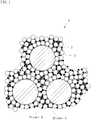
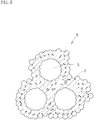
- the formed body 1 has a structure as shown in a conceptual image given in Fig. 1 .
- large particles of the pore formation material 2 are surrounded by a mixture of metal powder 3, the binder A and the binder B, and distribution is substantially uniform.
- Fig. 1 illustrates the binders A, B in the form of particle; however, the binders A and B melt during the molding step, and distribute to fill spaces between the particles.
- small black circles represent the binder A while large black circles represent the binder B.
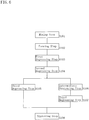
- temperature in the degreasing furnace is raised at a rate of 20°C/hour. As the temperature in the furnace reaches and goes beyond 210°C, the binder A begins draining. This is a first degreasing step S103 which continues until the pore formation material begins draining. In the first degreasing step S103, predetermined gaps are formed between the metal particles by the time when the pore formation material 2 begins to drain. In the present example, approximately 2 volume percent of the binder A drains in the first degreasing step.
- the binder A drains, the pore formation material 2 begins to drain, and further, the binder B begins to drain, i.e. a second degreasing step takes place.
- the pore formation material 2 begins draining at a temperature not lower than 240°C while the binder B begins draining at a temperature not lower than 255°C.
- the three components drain simultaneously in the second degreasing step.
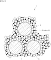
- Fig. 2 shows a state where the binder A has drained completely. For easier understanding, Fig.
- FIG. 2 illustrates as if no part of the pore formation material 2 or binder B has been drained; however, part of them has already been draining.
- draining of the binder A leaves continuous gap spaces 4 among the metal particles. Therefore, it is possible to drain the pore formation material 2 smoothly via these gap spaces.
- the binder B is present and provides bonding between the metal particles, a sufficient level of strength is maintained while the pore formation material drains. Further, as the draining speed of the pore formation material 2 increases, so does the amount of the binder draining, providing sufficient gap space for the pore formation material to drain through. Therefore, it is possible to let the pore formation material drain while keeping the shape of the pores 5.
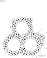
- the binder A and the pore formation material 2 have completely drained as shown in Fig. 3 , leaving the pores 5.
- the binder B is slightly softer, and provides bridging between the metal particles 3 thereby providing increased shape retentionability. Further, the binder B prevents the metal particles from dropping into the pores 5 which are left by the pore formation material. The metal particles do not change their relative positions, providing an intermediate degreased body of highly accurate shape and dimensions.
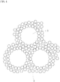
- a third degreasing step (S105), to remove the binder B.
- the third degreasing step leaves a degreased body as shown in Fig. 4 , formed by the metal particle 3.
- Fig. 4 illustrates as if the particles are separated from each other; however, there is only little shrinkage in the degreased body because the particles distribute in a three-dimensional manner in up-and-down directions in the drawing.
- the temperature of the furnace is increased beyond the sintering temperature of the metal, to perform a sintering step thereby sintering the metal particles.
- the sintering step causes metal particles to be bonded with adjacent metal particles, shrinks gap spaces between the adjacent particles, and yields a sintered body 6 as shown in Fig. 5 .
- the sintered body is shrunken from the formed body approximately by the amount of the binder mixed thereto.
- Fig. 7 shows how the pore formation material 2 and the binder (the entire body of A and B) decrease in the present example.
- the graph has its vertical axis representing the rate of decrease, and the horizontal axis representing the degreasing temperature.
- part of the binder A begins to drain in the present example. This provides a channel in the formed body, for the pore formation material 2 to drain through.
- the pore formation material 2 begins to drain: The rate of decrease in the pore formation material 2 exceeds that of the binder at a certain temperature, and this situation continues until the pore formation material drains completely, i.e. the pore formation material 2 completes draining before the binder does.
- the degreasing step is performed while securing drainage paths for the pore formation material 2 and while providing reinforcement by the binder, with part of the binder remaining un-drained even at a point when the pore formation material has completely drained. This enables to allow the degreasing step to proceed, with increased shape retentionability of the formed body.
- the binder B contains two binder components each having a different draining temperature from the other. This prevents premature draining of the remaining binder which remains after the pore formation material 2 has drained. Therefore, it is possible to prevent the formed body from being subjected to excessive stresses in the process when the binder drains. As a result, even after the pore formation material 2 has drained, the method provides good shape retentionability, enabling to prevent the formed body from deforming.
- Table 2 shows a combination ratio in a comparative example.
- the binder B which drains at a temperature higher than that of the pore formation material 2 is replaced by a binder C (polystyrene) which drains at a temperature lower than that of the pore formation material 2.
- All of the others in the combination ratio are identical with those in the embodiment example 1, so no more description will be given here.
- the third degreasing step is not performed in the comparative example since the binder B is not mixed thereto.
- the porous body had an approximately 60% porosity, matching to the combination ratio of the pore formation material 2.
- the porous body had an approximately 40% porosity despite the fact that the same combination ratio of the pore formation material was used.
- microscopic observation of the structure of the sintered body according to the embodiment example 1 revealed that the example 1 had substantially uniform, spherical pores.
- pore shapes were irregularly deformed and the sizes were smaller. From these observations, it became clear that a porous sintered body which has a high level of accuracy can be formed by using the binder B thereby retaining the shape which is formed with the metal particles, during the time when draining the pore formation material.
- the second degreasing step S104 may be followed by an interim work step S106. Since it is possible, according to the present embodiment, to retain the binder after the pore formation material has drained, a sufficient level of strength is retained in the porous formed body, and therefore, a variety of works can be performed to the sintered body even after the body became porous.
- the interim work step may include e.g. machining like in convention. Further, it is now possible to fill the pores and continuous pore spaces in the formed body with a variety of functional substances.
- the second degreasing step shrinks the formed body very little, so the pores have a large size.
- a high level of porosity allows use of fluid as a way to fill the spaces with functional substance, while it is also possible to use a mechanical method of filling a functional substance only in the surface.
- a substance which acts as a catalyst may be filled in the pores before sintering is performed in the sintering step. According to this process, the catalytic substance is fixed in inner walls of the pores, so it is now possible to fix expensive substances such as platinum inside of the pores.
- a porous formed body containing pores which communicate with each other are formed, then the particles 8 are filled, and thereafter, the third degreasing step S107 and the sintering step S108 are performed. Since the sintering step shrinks the pores 5, it is also possible to make the particles movable but inescapable from the pores.
- the fillers may be selected from metal oxides such as titanium oxide and functional ceramics such as apatite.
Landscapes
- Chemical & Material Sciences (AREA)
- Engineering & Computer Science (AREA)
- Ceramic Engineering (AREA)
- Materials Engineering (AREA)
- Structural Engineering (AREA)
- Organic Chemistry (AREA)
- Manufacturing & Machinery (AREA)
- Mechanical Engineering (AREA)
- Chemical Kinetics & Catalysis (AREA)
- General Chemical & Material Sciences (AREA)
- Powder Metallurgy (AREA)
- Filtering Materials (AREA)
- Health & Medical Sciences (AREA)
- Toxicology (AREA)
Claims (14)
- Procédé de préparation d'un corps fritté poreux, comprenant :une étape de préparation d'une pastille consistant à préparer une pastille composée par chauffage et mélange d'un composé de frittage contenant un liant, d'un matériau en poudre frittable et d'un matériau porogène à une température provoquant la fusion du liant mais ne provoquant pas le ramollissement du matériau porogène, moyennant quoi le composé de frittage contient le matériau porogène à raison de 50 à 80 % en volume du composé de frittage ;une étape de formation thermique consistant à mettre la pastille préparée dans l'étape de préparation de la pastille sous une forme prédéterminée à une température provoquant la fusion du liant mais ne provoquant pas la déformation du matériau porogène;une étape de dégraissage consistant à éliminer le liant du corps façonné obtenu à l'étape de formation thermique ; etune étape de frittage consistant à fritter le corps dégraissé après l'étape de dégraissage,dans lequel le liant contient un composant qui fond à la température atteinte lors de l'étape de préparation de la pastille et de l'étape de formation et qui s'écoule à une température supérieure à la température d'écoulement du matériau porogène, le matériau porogène s'écoulant dans l'étape de dégraissage et une partie du liant restant sans s'écouler,dans lequel le composant liant s'écoule à raison de 0,1 % en volume à 5,0 % en volume avant que le matériau porogène commence à s'écouler,dans lequel le composant liant reste sans s'écouler à raison de 5 % en volume à 40 % en volume suite à l'écoulement complet du matériau porogène, etdans lequel le corps fritté poreux a une porosité de 50 à 80 %.
- Procédé selon la revendication 1, dans lequel le liant contient : un composant s'écoulant à basse température qui commence à s'écouler à une température inférieure à une température d'écoulement du matériau porogène, et s'écoule à une température de dégraissage qui est inférieure à la température d'écoulement du matériau porogène ; et un composant s'écoulant à température élevée qui commence à s'écouler à une température supérieure à une température de début d'écoulement du matériau porogène, et s'écoule à une température de dégraissage qui est supérieure à la température d'écoulement du matériau porogène,
l'étape de dégraissage incluant :une première étape de dégraissage dans laquelle le composant s'écoulant à basse température est laissé à s'écouler et avant que le matériau porogène soit laissé à s'écouler ;une deuxième étape de dégraissage dans laquelle le matériau porogène est laissé à s'écouler complètement;une troisième étape de dégraissage dans laquelle le composant s'écoulant à température élevée est laissé à s'écouler complètement. - Procédé de préparation d'un corps fritté poreux selon la revendication 2, dans lequel le matériau porogène est laissé à s'écouler par des espaces formés par l'écoulement du composant s'écoulant à basse température ou des espaces formés par l'écoulement d'une partie du composant s'écoulant à température élevée, dans la deuxième étape de dégraissage.
- Procédé de préparation d'un corps fritté poreux selon la revendication 2, dans lequel le composant s'écoulant à température élevée contient au moins deux composants liants ayant chacun une température d'écoulement différente,
les composants liants ayant des températures d'écoulement différentes s'écoulant successivement dans la troisième étape de dégraissage. - Procédé de préparation d'un corps fritté poreux selon la revendication 2, comprenant en outre une étape d'usinage transitoire consistant à soumettre un corps dégraissé intermédiaire qui a subi la deuxième étape de dégraissage à un traitement intermédiaire.
- Procédé de préparation d'un corps fritté poreux ayant des pores continus selon la revendication 2, comprenant en outre
une étape de remplissage d'un matériau additionnel consistant à remplir d'un matériau additionnel prédéterminé tout ou partie des pores dans un corps dégraissé intermédiaire qui a subi la deuxième étape de dégraissage. - Procédé de préparation d'un corps fritté poreux selon la revendication 6, dans lequel la troisième étape de dégraissage et l'étape de frittage sont mises en oeuvre après l'étape de remplissage du matériau additionnel, le matériau additionnel étant fritté solidairement avec le composé de frittage dans une surface intérieure des pores.
- Procédé de préparation d'un corps fritté poreux selon la revendication 6, dans lequel la troisième étape de dégraissage et l'étape de frittage sont mises en oeuvre après l'étape de remplissage du matériau additionnel, le matériau additionnel étant maintenu mobile dans les pores.
- Procédé de préparation d'un corps fritté poreux selon la revendication 1, dans lequel le matériau porogène est mélangé en une proportion de 50 à 80 % en volume du composé de frittage.
- Procédé de préparation d'un corps fritté poreux selon la revendication 1, dans lequel l'étape de formation emploie un procédé de moulage par injection.
- Composé de frittage de formation thermique contenant un liant, un matériau en poudre frittable et un matériau porogène, pour une mise sous une forme prédéterminée dans une étape de formation thermique, élimination du liant dans une étape de dégraissage, et frittage du matériau en poudre dans une étape de frittage, moyennant quoi le composé de frittage contient le matériau porogène à raison de 50 à 80 % en volume du composé de frittage,
dans lequel le liant contient :un composant s'écoulant à basse température, qui est adapté pour fondre dans l'étape de formation thermique, est adapté pour commencer à s'écouler à une température inférieure à une température d'écoulement du matériau porogène, et est adapté pour s'écouler à une température inférieure à une température à laquelle s'écoule le matériau porogène ; etun composant s'écoulant à température élevée, qui est adapté pour fondre dans l'étape de formation thermique, est adapté pour commencer à s'écouler après que le matériau porogène commence à s'écouler, et est adapté pour s'écouler à une température supérieure à celle du matériau porogène,dans lequel le composant liant est adapté pour s'écouler à raison de 0,1 % en volume à 5,0 % en volume avant que le matériau porogène commence à s'écouler, etdans lequel le composant liant est adapté pour rester sans s'écouler à raison de 5 % en volume à 40 % en volume suite à l'écoulement complet du matériau porogène. - Composé de frittage selon la revendication 11, dans lequel le liant contient le composant s'écoulant à basse température à raison de 40 % en volume à 70 % en volume.
- Composé de frittage pour un corps poreux selon la revendication 11, dans lequel le composant s'écoulant à une température élevée contient au moins deux composants liants, chacun étant adapté pour s'écouler à une température d'écoulement différente de celle des autres, après que le matériau porogène s'est écoulé.
- Composé de frittage pour un corps poreux selon la revendication 11, contenant le matériau porogène à raison de 50 à 80 % en volume du composé de frittage.
Applications Claiming Priority (2)
| Application Number | Priority Date | Filing Date | Title |
|---|---|---|---|
| JP2004301482 | 2004-10-15 | ||
| PCT/JP2005/018850 WO2006041118A1 (fr) | 2004-10-15 | 2005-10-13 | Procede de production d'agglomere poreux, materiau de moulage d'agglomere poreux et agglomere poreux associe |
Publications (3)
| Publication Number | Publication Date |
|---|---|
| EP1808243A1 EP1808243A1 (fr) | 2007-07-18 |
| EP1808243A4 EP1808243A4 (fr) | 2010-07-14 |
| EP1808243B1 true EP1808243B1 (fr) | 2019-03-20 |
Family
ID=36148405
Family Applications (1)
| Application Number | Title | Priority Date | Filing Date |
|---|---|---|---|
| EP05793657.7A Active EP1808243B1 (fr) | 2004-10-15 | 2005-10-13 | Procede de production d'agglomere poreux, materiau de moulage d'agglomere poreux et agglomere poreux associe |
Country Status (5)
| Country | Link |
|---|---|
| US (3) | US9272333B2 (fr) |
| EP (1) | EP1808243B1 (fr) |
| JP (1) | JP5503838B2 (fr) |
| ES (1) | ES2738003T3 (fr) |
| WO (1) | WO2006041118A1 (fr) |
Cited By (1)
| Publication number | Priority date | Publication date | Assignee | Title |
|---|---|---|---|---|
| US11819917B2 (en) | 2004-10-15 | 2023-11-21 | Taisei Kogyo Co., Ltd. | Method of making a porous sintered body, a compound for making the porous sintered body, and the porous sintered body |
Families Citing this family (10)
| Publication number | Priority date | Publication date | Assignee | Title |
|---|---|---|---|---|
| JP5168451B2 (ja) * | 2007-03-13 | 2013-03-21 | 独立行政法人 宇宙航空研究開発機構 | 多孔質成形体の製造方法及び多孔質充填成形体の製造方法 |
| US8017070B2 (en) * | 2007-05-17 | 2011-09-13 | The Boeing Company | Direct to metal sintering of 17-4PH steel |
| EP2799166A4 (fr) * | 2011-12-28 | 2016-06-15 | Taisei Kogyo Co Ltd | Corps fritté poreux et procédé de production de corps fritté poreux |
| EP2966184B1 (fr) * | 2013-03-05 | 2023-06-07 | Taisei Kogyo Co., Ltd. | Matière frittée poreuse et procédé de fabrication d'une matière frittée poreuse |
| EP3640320A4 (fr) | 2017-06-12 | 2021-03-17 | Mitsubishi Paper Mills Limited | Gabarit de cryoconservation pour la cryoconservation de cellules ou de tissus |
| ES2695849B2 (es) * | 2017-07-05 | 2019-08-06 | Univ Alicante | Materiales espumados de poro interconectado con fases huesped, procedimiento para la preparacion de dichos materiales y usos de los mismos. |
| KR20220034882A (ko) | 2019-07-19 | 2022-03-18 | 엔테그리스, 아이엔씨. | 다공성 소결 멤브레인 및 다공성 소결 멤브레인을 제조하는 방법 |
| JP2021159843A (ja) * | 2020-03-31 | 2021-10-11 | 株式会社U・M・R | 担持触媒の製造方法 |
| US20240199494A1 (en) * | 2021-04-16 | 2024-06-20 | Kuraray Noritake Dental lnc. | Zirconia molded body, zirconia pre-sintered body, and zirconia sintered body, and methods of production thereof |
| CN113828778B (zh) * | 2021-09-23 | 2023-12-19 | 东睦新材料集团股份有限公司 | 一种水溶性粘结剂、粘结剂的制备方法及制备零件的方法 |
Family Cites Families (17)
| Publication number | Priority date | Publication date | Assignee | Title |
|---|---|---|---|---|
| JPH01164755A (ja) * | 1987-08-31 | 1989-06-28 | Toshiba Corp | セラミック射出成形用バインダー組成物 |
| DE68912613T2 (de) * | 1988-02-18 | 1994-05-11 | Sanyo Chemical Ind Ltd | Formbare Zusammensetzung. |
| JPH0459655A (ja) * | 1990-06-29 | 1992-02-26 | Tokai Carbon Co Ltd | セラミックス焼結体の製造方法 |
| JPH0941004A (ja) * | 1995-08-04 | 1997-02-10 | Olympus Optical Co Ltd | 金属粉末射出成形方法 |
| US5641920A (en) * | 1995-09-07 | 1997-06-24 | Thermat Precision Technology, Inc. | Powder and binder systems for use in powder molding |
| JP4187314B2 (ja) * | 1998-06-29 | 2008-11-26 | 株式会社イノアックコーポレーション | 金属多孔体の製造方法 |
| JP4019522B2 (ja) * | 1998-10-13 | 2007-12-12 | セイコーエプソン株式会社 | 焼結体の製造方法 |
| JP4441059B2 (ja) * | 1999-04-28 | 2010-03-31 | 日本碍子株式会社 | ハニカム成形体及びその製造方法 |
| JP4514274B2 (ja) | 2000-02-29 | 2010-07-28 | 京セラ株式会社 | 多孔質セラミック構造体の製造方法 |
| US6376585B1 (en) * | 2000-06-26 | 2002-04-23 | Apex Advanced Technologies, Llc | Binder system and method for particulate material with debind rate control additive |
| DE10063220A1 (de) * | 2000-12-19 | 2002-06-20 | Basf Ag | NOx-Speicher-Katalysator, Verfahren zu seiner Herstellung sowie seine Verwendung |
| US6852272B2 (en) * | 2001-03-07 | 2005-02-08 | Advanced Ceramics Research, Inc. | Method for preparation of metallic and ceramic foam products and products made |
| JP3832729B2 (ja) * | 2001-10-26 | 2006-10-11 | 日立金属株式会社 | 多孔質焼結体の製造方法 |
| EP1382408B1 (fr) * | 2002-07-15 | 2010-06-23 | Hitachi Metals, Ltd. | Procédé de fabrication de métal poreux fritté pour filtres |
| DE10248888B4 (de) * | 2002-10-18 | 2005-01-27 | Forschungszentrum Jülich GmbH | Verfahren zur Herstellung endkonturnaher, metallischer und/oder keramischer Bauteile |
| JP5503838B2 (ja) | 2004-10-15 | 2014-05-28 | 太盛工業株式会社 | 多孔質焼結体の製造方法、多孔質焼結成形材料及び多孔質焼結体 |
| DE102006049844A1 (de) * | 2006-10-20 | 2008-04-24 | Gkss-Forschungszentrum Geesthacht Gmbh | Verfahren zur Herstellung von Bauteilen für Verbrennungsmotoren oder Turbinen |
-
2005
- 2005-10-13 JP JP2006540963A patent/JP5503838B2/ja active Active
- 2005-10-13 EP EP05793657.7A patent/EP1808243B1/fr active Active
- 2005-10-13 US US11/665,017 patent/US9272333B2/en active Active
- 2005-10-13 ES ES05793657T patent/ES2738003T3/es active Active
- 2005-10-13 WO PCT/JP2005/018850 patent/WO2006041118A1/fr active Application Filing
-
2015
- 2015-12-08 US US14/962,466 patent/US20160090327A1/en not_active Abandoned
-
2019
- 2019-08-20 US US16/545,646 patent/US11819917B2/en active Active
Non-Patent Citations (1)
| Title |
|---|
| None * |
Cited By (1)
| Publication number | Priority date | Publication date | Assignee | Title |
|---|---|---|---|---|
| US11819917B2 (en) | 2004-10-15 | 2023-11-21 | Taisei Kogyo Co., Ltd. | Method of making a porous sintered body, a compound for making the porous sintered body, and the porous sintered body |
Also Published As
| Publication number | Publication date |
|---|---|
| US20190367419A1 (en) | 2019-12-05 |
| US20160090327A1 (en) | 2016-03-31 |
| WO2006041118A1 (fr) | 2006-04-20 |
| JPWO2006041118A1 (ja) | 2008-08-07 |
| US11819917B2 (en) | 2023-11-21 |
| EP1808243A1 (fr) | 2007-07-18 |
| US20090202821A1 (en) | 2009-08-13 |
| JP5503838B2 (ja) | 2014-05-28 |
| EP1808243A4 (fr) | 2010-07-14 |
| US9272333B2 (en) | 2016-03-01 |
| ES2738003T3 (es) | 2020-01-17 |
Similar Documents
| Publication | Publication Date | Title |
|---|---|---|
| US11819917B2 (en) | Method of making a porous sintered body, a compound for making the porous sintered body, and the porous sintered body | |
| EP0311407B1 (fr) | Procédé pour la fabrication de pièces à partir de matériau en forme de poudre | |
| EP0988839B1 (fr) | Procédé de fabrication des implants au moins partiellement poreux par moulage à injection à haute précision | |
| US6746506B2 (en) | Blended powder solid-supersolidus liquid phase sintering | |
| US5531958A (en) | Process for improving the debinding rate of ceramic and metal injection molded products | |
| EP3643693B1 (fr) | Liant pour composition de moulage par injection | |
| CN104837584B (zh) | 用于制造多孔部件的方法及其部件 | |
| EP2907604B1 (fr) | Procédé de fabrication d'un composant poreux et composant poreux | |
| JPH06316709A (ja) | ドーム形押出ダイおよびその製造方法 | |
| KR102277881B1 (ko) | 사출 성형 조성물용 바인더 | |
| WO2006004011A1 (fr) | Filtre et méthode de fabrication de celui-ci | |
| US20180014937A1 (en) | Nitinol metal injection molding of porous, orthopedic implants with a titanium substrate | |
| Moritz et al. | Hybridization of materials and processes by additive manufacturing | |
| KR100340590B1 (ko) | 분말사출성형용결합제및이를이용한분말사출성형방법 | |
| KR101837977B1 (ko) | 금속사출성형법을 이용한 금속 다공체의 제조방법 | |
| CN105669206A (zh) | 多孔碳化硅陶瓷及其制备方法 | |
| JPH08127805A (ja) | 金属粉末焼結体の製造方法 | |
| Matsuzaki et al. | PM Lightweight and Porous Materials: Production of Porous Metal Materials by Injection and Extrusion Moulding | |
| WO2005011900A1 (fr) | Composition de moulage pour le frittage des poudres, procede de frittage de poudres pour frittage, et element fritte obtenu a partir d'une telle poudre | |
| JPH03177504A (ja) | 射出成形用金属粉末 |
Legal Events
| Date | Code | Title | Description |
|---|---|---|---|
| PUAI | Public reference made under article 153(3) epc to a published international application that has entered the european phase |
Free format text: ORIGINAL CODE: 0009012 |
|
| 17P | Request for examination filed |
Effective date: 20070510 |
|
| AK | Designated contracting states |
Kind code of ref document: A1 Designated state(s): AT BE BG CH CY CZ DE DK EE ES FI FR GB GR HU IE IS IT LI LT LU LV MC NL PL PT RO SE SI SK TR |
|
| DAX | Request for extension of the european patent (deleted) | ||
| A4 | Supplementary search report drawn up and despatched |
Effective date: 20100611 |
|
| 17Q | First examination report despatched |
Effective date: 20160712 |
|
| STAA | Information on the status of an ep patent application or granted ep patent |
Free format text: STATUS: EXAMINATION IS IN PROGRESS |
|
| GRAP | Despatch of communication of intention to grant a patent |
Free format text: ORIGINAL CODE: EPIDOSNIGR1 |
|
| STAA | Information on the status of an ep patent application or granted ep patent |
Free format text: STATUS: GRANT OF PATENT IS INTENDED |
|
| RIC1 | Information provided on ipc code assigned before grant |
Ipc: C04B 38/04 20060101ALI20180907BHEP Ipc: C04B 111/00 20060101ALI20180907BHEP Ipc: B22F 3/02 20060101ALI20180907BHEP Ipc: C04B 38/02 20060101ALI20180907BHEP Ipc: C04B 38/00 20060101ALI20180907BHEP Ipc: B22F 3/11 20060101AFI20180907BHEP Ipc: B22F 3/10 20060101ALI20180907BHEP |
|
| INTG | Intention to grant announced |
Effective date: 20180926 |
|
| GRAS | Grant fee paid |
Free format text: ORIGINAL CODE: EPIDOSNIGR3 |
|
| GRAA | (expected) grant |
Free format text: ORIGINAL CODE: 0009210 |
|
| STAA | Information on the status of an ep patent application or granted ep patent |
Free format text: STATUS: THE PATENT HAS BEEN GRANTED |
|
| AK | Designated contracting states |
Kind code of ref document: B1 Designated state(s): AT BE BG CH CY CZ DE DK EE ES FI FR GB GR HU IE IS IT LI LT LU LV MC NL PL PT RO SE SI SK TR |
|
| REG | Reference to a national code |
Ref country code: GB Ref legal event code: FG4D |
|
| REG | Reference to a national code |
Ref country code: CH Ref legal event code: EP |
|
| REG | Reference to a national code |
Ref country code: DE Ref legal event code: R096 Ref document number: 602005055533 Country of ref document: DE |
|
| REG | Reference to a national code |
Ref country code: AT Ref legal event code: REF Ref document number: 1110035 Country of ref document: AT Kind code of ref document: T Effective date: 20190415 |
|
| REG | Reference to a national code |
Ref country code: IE Ref legal event code: FG4D |
|
| REG | Reference to a national code |
Ref country code: NL Ref legal event code: MP Effective date: 20190320 |
|
| PG25 | Lapsed in a contracting state [announced via postgrant information from national office to epo] |
Ref country code: LT Free format text: LAPSE BECAUSE OF FAILURE TO SUBMIT A TRANSLATION OF THE DESCRIPTION OR TO PAY THE FEE WITHIN THE PRESCRIBED TIME-LIMIT Effective date: 20190320 Ref country code: SE Free format text: LAPSE BECAUSE OF FAILURE TO SUBMIT A TRANSLATION OF THE DESCRIPTION OR TO PAY THE FEE WITHIN THE PRESCRIBED TIME-LIMIT Effective date: 20190320 Ref country code: FI Free format text: LAPSE BECAUSE OF FAILURE TO SUBMIT A TRANSLATION OF THE DESCRIPTION OR TO PAY THE FEE WITHIN THE PRESCRIBED TIME-LIMIT Effective date: 20190320 |
|
| REG | Reference to a national code |
Ref country code: LT Ref legal event code: MG4D |
|
| PG25 | Lapsed in a contracting state [announced via postgrant information from national office to epo] |
Ref country code: BG Free format text: LAPSE BECAUSE OF FAILURE TO SUBMIT A TRANSLATION OF THE DESCRIPTION OR TO PAY THE FEE WITHIN THE PRESCRIBED TIME-LIMIT Effective date: 20190620 Ref country code: GR Free format text: LAPSE BECAUSE OF FAILURE TO SUBMIT A TRANSLATION OF THE DESCRIPTION OR TO PAY THE FEE WITHIN THE PRESCRIBED TIME-LIMIT Effective date: 20190621 Ref country code: LV Free format text: LAPSE BECAUSE OF FAILURE TO SUBMIT A TRANSLATION OF THE DESCRIPTION OR TO PAY THE FEE WITHIN THE PRESCRIBED TIME-LIMIT Effective date: 20190320 Ref country code: NL Free format text: LAPSE BECAUSE OF FAILURE TO SUBMIT A TRANSLATION OF THE DESCRIPTION OR TO PAY THE FEE WITHIN THE PRESCRIBED TIME-LIMIT Effective date: 20190320 |
|
| REG | Reference to a national code |
Ref country code: AT Ref legal event code: MK05 Ref document number: 1110035 Country of ref document: AT Kind code of ref document: T Effective date: 20190320 |
|
| PG25 | Lapsed in a contracting state [announced via postgrant information from national office to epo] |
Ref country code: RO Free format text: LAPSE BECAUSE OF FAILURE TO SUBMIT A TRANSLATION OF THE DESCRIPTION OR TO PAY THE FEE WITHIN THE PRESCRIBED TIME-LIMIT Effective date: 20190320 Ref country code: SK Free format text: LAPSE BECAUSE OF FAILURE TO SUBMIT A TRANSLATION OF THE DESCRIPTION OR TO PAY THE FEE WITHIN THE PRESCRIBED TIME-LIMIT Effective date: 20190320 Ref country code: CZ Free format text: LAPSE BECAUSE OF FAILURE TO SUBMIT A TRANSLATION OF THE DESCRIPTION OR TO PAY THE FEE WITHIN THE PRESCRIBED TIME-LIMIT Effective date: 20190320 Ref country code: PT Free format text: LAPSE BECAUSE OF FAILURE TO SUBMIT A TRANSLATION OF THE DESCRIPTION OR TO PAY THE FEE WITHIN THE PRESCRIBED TIME-LIMIT Effective date: 20190720 Ref country code: EE Free format text: LAPSE BECAUSE OF FAILURE TO SUBMIT A TRANSLATION OF THE DESCRIPTION OR TO PAY THE FEE WITHIN THE PRESCRIBED TIME-LIMIT Effective date: 20190320 |
|
| PG25 | Lapsed in a contracting state [announced via postgrant information from national office to epo] |
Ref country code: PL Free format text: LAPSE BECAUSE OF FAILURE TO SUBMIT A TRANSLATION OF THE DESCRIPTION OR TO PAY THE FEE WITHIN THE PRESCRIBED TIME-LIMIT Effective date: 20190320 |
|
| PG25 | Lapsed in a contracting state [announced via postgrant information from national office to epo] |
Ref country code: IS Free format text: LAPSE BECAUSE OF FAILURE TO SUBMIT A TRANSLATION OF THE DESCRIPTION OR TO PAY THE FEE WITHIN THE PRESCRIBED TIME-LIMIT Effective date: 20190720 Ref country code: AT Free format text: LAPSE BECAUSE OF FAILURE TO SUBMIT A TRANSLATION OF THE DESCRIPTION OR TO PAY THE FEE WITHIN THE PRESCRIBED TIME-LIMIT Effective date: 20190320 |
|
| REG | Reference to a national code |
Ref country code: DE Ref legal event code: R097 Ref document number: 602005055533 Country of ref document: DE |
|
| REG | Reference to a national code |
Ref country code: ES Ref legal event code: FG2A Ref document number: 2738003 Country of ref document: ES Kind code of ref document: T3 Effective date: 20200117 |
|
| PLBE | No opposition filed within time limit |
Free format text: ORIGINAL CODE: 0009261 |
|
| STAA | Information on the status of an ep patent application or granted ep patent |
Free format text: STATUS: NO OPPOSITION FILED WITHIN TIME LIMIT |
|
| PG25 | Lapsed in a contracting state [announced via postgrant information from national office to epo] |
Ref country code: DK Free format text: LAPSE BECAUSE OF FAILURE TO SUBMIT A TRANSLATION OF THE DESCRIPTION OR TO PAY THE FEE WITHIN THE PRESCRIBED TIME-LIMIT Effective date: 20190320 |
|
| 26N | No opposition filed |
Effective date: 20200102 |
|
| PG25 | Lapsed in a contracting state [announced via postgrant information from national office to epo] |
Ref country code: SI Free format text: LAPSE BECAUSE OF FAILURE TO SUBMIT A TRANSLATION OF THE DESCRIPTION OR TO PAY THE FEE WITHIN THE PRESCRIBED TIME-LIMIT Effective date: 20190320 |
|
| PG25 | Lapsed in a contracting state [announced via postgrant information from national office to epo] |
Ref country code: TR Free format text: LAPSE BECAUSE OF FAILURE TO SUBMIT A TRANSLATION OF THE DESCRIPTION OR TO PAY THE FEE WITHIN THE PRESCRIBED TIME-LIMIT Effective date: 20190320 |
|
| PG25 | Lapsed in a contracting state [announced via postgrant information from national office to epo] |
Ref country code: MC Free format text: LAPSE BECAUSE OF FAILURE TO SUBMIT A TRANSLATION OF THE DESCRIPTION OR TO PAY THE FEE WITHIN THE PRESCRIBED TIME-LIMIT Effective date: 20190320 |
|
| PG25 | Lapsed in a contracting state [announced via postgrant information from national office to epo] |
Ref country code: LU Free format text: LAPSE BECAUSE OF NON-PAYMENT OF DUE FEES Effective date: 20191013 |
|
| REG | Reference to a national code |
Ref country code: BE Ref legal event code: MM Effective date: 20191031 |
|
| PG25 | Lapsed in a contracting state [announced via postgrant information from national office to epo] |
Ref country code: BE Free format text: LAPSE BECAUSE OF NON-PAYMENT OF DUE FEES Effective date: 20191031 |
|
| PG25 | Lapsed in a contracting state [announced via postgrant information from national office to epo] |
Ref country code: FR Free format text: LAPSE BECAUSE OF NON-PAYMENT OF DUE FEES Effective date: 20191031 Ref country code: IE Free format text: LAPSE BECAUSE OF NON-PAYMENT OF DUE FEES Effective date: 20191013 |
|
| PG25 | Lapsed in a contracting state [announced via postgrant information from national office to epo] |
Ref country code: CY Free format text: LAPSE BECAUSE OF FAILURE TO SUBMIT A TRANSLATION OF THE DESCRIPTION OR TO PAY THE FEE WITHIN THE PRESCRIBED TIME-LIMIT Effective date: 20190320 |
|
| PG25 | Lapsed in a contracting state [announced via postgrant information from national office to epo] |
Ref country code: HU Free format text: LAPSE BECAUSE OF FAILURE TO SUBMIT A TRANSLATION OF THE DESCRIPTION OR TO PAY THE FEE WITHIN THE PRESCRIBED TIME-LIMIT; INVALID AB INITIO Effective date: 20051013 |
|
| PGFP | Annual fee paid to national office [announced via postgrant information from national office to epo] |
Ref country code: IT Payment date: 20221028 Year of fee payment: 18 Ref country code: GB Payment date: 20221027 Year of fee payment: 18 Ref country code: ES Payment date: 20221118 Year of fee payment: 18 Ref country code: DE Payment date: 20221031 Year of fee payment: 18 |
|
| PGFP | Annual fee paid to national office [announced via postgrant information from national office to epo] |
Ref country code: CH Payment date: 20221124 Year of fee payment: 18 |
|
| REG | Reference to a national code |
Ref country code: DE Ref legal event code: R119 Ref document number: 602005055533 Country of ref document: DE |
|
| REG | Reference to a national code |
Ref country code: CH Ref legal event code: PL |
|
| GBPC | Gb: european patent ceased through non-payment of renewal fee |
Effective date: 20231013 |
|
| PG25 | Lapsed in a contracting state [announced via postgrant information from national office to epo] |
Ref country code: GB Free format text: LAPSE BECAUSE OF NON-PAYMENT OF DUE FEES Effective date: 20231013 |
|
| PG25 | Lapsed in a contracting state [announced via postgrant information from national office to epo] |
Ref country code: CH Free format text: LAPSE BECAUSE OF NON-PAYMENT OF DUE FEES Effective date: 20231031 |
|
| PG25 | Lapsed in a contracting state [announced via postgrant information from national office to epo] |
Ref country code: GB Free format text: LAPSE BECAUSE OF NON-PAYMENT OF DUE FEES Effective date: 20231013 Ref country code: DE Free format text: LAPSE BECAUSE OF NON-PAYMENT OF DUE FEES Effective date: 20240501 Ref country code: CH Free format text: LAPSE BECAUSE OF NON-PAYMENT OF DUE FEES Effective date: 20231031 |