EP1808192B1 - Pre-filled syringe - Google Patents
Pre-filled syringe Download PDFInfo
- Publication number
- EP1808192B1 EP1808192B1 EP07000079.9A EP07000079A EP1808192B1 EP 1808192 B1 EP1808192 B1 EP 1808192B1 EP 07000079 A EP07000079 A EP 07000079A EP 1808192 B1 EP1808192 B1 EP 1808192B1
- Authority
- EP
- European Patent Office
- Prior art keywords
- gasket
- barrel
- base end
- filled syringe
- liquid flow
- Prior art date
- Legal status (The legal status is an assumption and is not a legal conclusion. Google has not performed a legal analysis and makes no representation as to the accuracy of the status listed.)
- Active
Links
- 229940071643 prefilled syringe Drugs 0.000 title claims description 58
- 239000007788 liquid Substances 0.000 claims description 83
- 239000003814 drug Substances 0.000 claims description 75
- 230000004308 accommodation Effects 0.000 claims description 30
- 238000004891 communication Methods 0.000 claims description 5
- 238000005192 partition Methods 0.000 claims description 3
- 238000000638 solvent extraction Methods 0.000 claims description 3
- 238000002347 injection Methods 0.000 description 37
- 239000007924 injection Substances 0.000 description 37
- 239000000463 material Substances 0.000 description 34
- 239000003708 ampul Substances 0.000 description 14
- -1 polyethylene Polymers 0.000 description 12
- 239000000243 solution Substances 0.000 description 12
- 238000002360 preparation method Methods 0.000 description 9
- 238000000926 separation method Methods 0.000 description 9
- 229920000219 Ethylene vinyl alcohol Polymers 0.000 description 8
- 238000004090 dissolution Methods 0.000 description 8
- 239000005038 ethylene vinyl acetate Substances 0.000 description 8
- 229920001200 poly(ethylene-vinyl acetate) Polymers 0.000 description 8
- 229920000139 polyethylene terephthalate Polymers 0.000 description 8
- 239000005020 polyethylene terephthalate Substances 0.000 description 8
- 229920002379 silicone rubber Polymers 0.000 description 8
- 230000004323 axial length Effects 0.000 description 6
- 239000000843 powder Substances 0.000 description 6
- 230000001012 protector Effects 0.000 description 6
- 238000000034 method Methods 0.000 description 5
- 239000004677 Nylon Substances 0.000 description 4
- 239000004952 Polyamide Substances 0.000 description 4
- 239000004698 Polyethylene Substances 0.000 description 4
- 239000004743 Polypropylene Substances 0.000 description 4
- 229920001328 Polyvinylidene chloride Polymers 0.000 description 4
- 229920005549 butyl rubber Polymers 0.000 description 4
- UUAGAQFQZIEFAH-UHFFFAOYSA-N chlorotrifluoroethylene Chemical group FC(F)=C(F)Cl UUAGAQFQZIEFAH-UHFFFAOYSA-N 0.000 description 4
- 239000013013 elastic material Substances 0.000 description 4
- 238000010828 elution Methods 0.000 description 4
- UFRKOOWSQGXVKV-UHFFFAOYSA-N ethene;ethenol Chemical compound C=C.OC=C UFRKOOWSQGXVKV-UHFFFAOYSA-N 0.000 description 4
- 239000004715 ethylene vinyl alcohol Substances 0.000 description 4
- 239000011521 glass Substances 0.000 description 4
- 239000000203 mixture Substances 0.000 description 4
- 229920001778 nylon Polymers 0.000 description 4
- 229920002647 polyamide Polymers 0.000 description 4
- 229920000728 polyester Polymers 0.000 description 4
- 229920000573 polyethylene Polymers 0.000 description 4
- 229920005672 polyolefin resin Polymers 0.000 description 4
- 229920001155 polypropylene Polymers 0.000 description 4
- 239000004800 polyvinyl chloride Substances 0.000 description 4
- 229920000915 polyvinyl chloride Polymers 0.000 description 4
- 229920002620 polyvinyl fluoride Polymers 0.000 description 4
- 239000005033 polyvinylidene chloride Substances 0.000 description 4
- 238000007789 sealing Methods 0.000 description 4
- 239000004945 silicone rubber Substances 0.000 description 4
- 229920002725 thermoplastic elastomer Polymers 0.000 description 4
- 230000002093 peripheral effect Effects 0.000 description 3
- 239000000126 substance Substances 0.000 description 3
- 241000894006 Bacteria Species 0.000 description 2
- 238000007599 discharging Methods 0.000 description 2
- 229940079593 drug Drugs 0.000 description 2
- 229920001971 elastomer Polymers 0.000 description 2
- 238000007667 floating Methods 0.000 description 2
- 230000003993 interaction Effects 0.000 description 2
- 239000002245 particle Substances 0.000 description 2
- 239000005060 rubber Substances 0.000 description 2
- 229920003002 synthetic resin Polymers 0.000 description 2
- 239000000057 synthetic resin Substances 0.000 description 2
- WQZGKKKJIJFFOK-GASJEMHNSA-N Glucose Natural products OC[C@H]1OC(O)[C@H](O)[C@@H](O)[C@@H]1O WQZGKKKJIJFFOK-GASJEMHNSA-N 0.000 description 1
- 239000003242 anti bacterial agent Substances 0.000 description 1
- 230000003115 biocidal effect Effects 0.000 description 1
- 238000010276 construction Methods 0.000 description 1
- 230000001419 dependent effect Effects 0.000 description 1
- 239000006185 dispersion Substances 0.000 description 1
- 239000008103 glucose Substances 0.000 description 1
- 229920003023 plastic Polymers 0.000 description 1
- 239000004033 plastic Substances 0.000 description 1
- 239000002994 raw material Substances 0.000 description 1
- 239000012266 salt solution Substances 0.000 description 1
- 230000001988 toxicity Effects 0.000 description 1
- 231100000419 toxicity Toxicity 0.000 description 1
Images


Classifications
-
- A—HUMAN NECESSITIES
- A61—MEDICAL OR VETERINARY SCIENCE; HYGIENE
- A61M—DEVICES FOR INTRODUCING MEDIA INTO, OR ONTO, THE BODY; DEVICES FOR TRANSDUCING BODY MEDIA OR FOR TAKING MEDIA FROM THE BODY; DEVICES FOR PRODUCING OR ENDING SLEEP OR STUPOR
- A61M5/00—Devices for bringing media into the body in a subcutaneous, intra-vascular or intramuscular way; Accessories therefor, e.g. filling or cleaning devices, arm-rests
- A61M5/178—Syringes
- A61M5/31—Details
- A61M5/3129—Syringe barrels
- A61M5/3134—Syringe barrels characterised by constructional features of the distal end, i.e. end closest to the tip of the needle cannula
-
- A—HUMAN NECESSITIES
- A61—MEDICAL OR VETERINARY SCIENCE; HYGIENE
- A61M—DEVICES FOR INTRODUCING MEDIA INTO, OR ONTO, THE BODY; DEVICES FOR TRANSDUCING BODY MEDIA OR FOR TAKING MEDIA FROM THE BODY; DEVICES FOR PRODUCING OR ENDING SLEEP OR STUPOR
- A61M5/00—Devices for bringing media into the body in a subcutaneous, intra-vascular or intramuscular way; Accessories therefor, e.g. filling or cleaning devices, arm-rests
- A61M5/178—Syringes
- A61M5/31—Details
- A61M5/3129—Syringe barrels
- A61M2005/3132—Syringe barrels having flow passages for injection agents at the distal end of the barrel to bypass a sealing stopper after its displacement to this end due to internal pressure increase
-
- A—HUMAN NECESSITIES
- A61—MEDICAL OR VETERINARY SCIENCE; HYGIENE
- A61M—DEVICES FOR INTRODUCING MEDIA INTO, OR ONTO, THE BODY; DEVICES FOR TRANSDUCING BODY MEDIA OR FOR TAKING MEDIA FROM THE BODY; DEVICES FOR PRODUCING OR ENDING SLEEP OR STUPOR
- A61M5/00—Devices for bringing media into the body in a subcutaneous, intra-vascular or intramuscular way; Accessories therefor, e.g. filling or cleaning devices, arm-rests
- A61M5/178—Syringes
- A61M5/31—Details
- A61M5/3129—Syringe barrels
- A61M5/3137—Specially designed finger grip means, e.g. for easy manipulation of the syringe rod
- A61M2005/3139—Finger grips not integrally formed with the syringe barrel, e.g. using adapter with finger grips
-
- A—HUMAN NECESSITIES
- A61—MEDICAL OR VETERINARY SCIENCE; HYGIENE
- A61M—DEVICES FOR INTRODUCING MEDIA INTO, OR ONTO, THE BODY; DEVICES FOR TRANSDUCING BODY MEDIA OR FOR TAKING MEDIA FROM THE BODY; DEVICES FOR PRODUCING OR ENDING SLEEP OR STUPOR
- A61M5/00—Devices for bringing media into the body in a subcutaneous, intra-vascular or intramuscular way; Accessories therefor, e.g. filling or cleaning devices, arm-rests
- A61M5/178—Syringes
- A61M5/31—Details
- A61M5/315—Pistons; Piston-rods; Guiding, blocking or restricting the movement of the rod or piston; Appliances on the rod for facilitating dosing ; Dosing mechanisms
- A61M5/31596—Pistons; Piston-rods; Guiding, blocking or restricting the movement of the rod or piston; Appliances on the rod for facilitating dosing ; Dosing mechanisms comprising means for injection of two or more media, e.g. by mixing
-
- A—HUMAN NECESSITIES
- A61—MEDICAL OR VETERINARY SCIENCE; HYGIENE
- A61M—DEVICES FOR INTRODUCING MEDIA INTO, OR ONTO, THE BODY; DEVICES FOR TRANSDUCING BODY MEDIA OR FOR TAKING MEDIA FROM THE BODY; DEVICES FOR PRODUCING OR ENDING SLEEP OR STUPOR
- A61M5/00—Devices for bringing media into the body in a subcutaneous, intra-vascular or intramuscular way; Accessories therefor, e.g. filling or cleaning devices, arm-rests
- A61M5/178—Syringes
- A61M5/31—Details
- A61M5/32—Needles; Details of needles pertaining to their connection with syringe or hub; Accessories for bringing the needle into, or holding the needle on, the body; Devices for protection of needles
- A61M5/3202—Devices for protection of the needle before use, e.g. caps
-
- A—HUMAN NECESSITIES
- A61—MEDICAL OR VETERINARY SCIENCE; HYGIENE
- A61M—DEVICES FOR INTRODUCING MEDIA INTO, OR ONTO, THE BODY; DEVICES FOR TRANSDUCING BODY MEDIA OR FOR TAKING MEDIA FROM THE BODY; DEVICES FOR PRODUCING OR ENDING SLEEP OR STUPOR
- A61M5/00—Devices for bringing media into the body in a subcutaneous, intra-vascular or intramuscular way; Accessories therefor, e.g. filling or cleaning devices, arm-rests
- A61M5/178—Syringes
- A61M5/31—Details
- A61M5/32—Needles; Details of needles pertaining to their connection with syringe or hub; Accessories for bringing the needle into, or holding the needle on, the body; Devices for protection of needles
- A61M5/34—Constructions for connecting the needle, e.g. to syringe nozzle or needle hub
- A61M5/347—Constructions for connecting the needle, e.g. to syringe nozzle or needle hub rotatable, e.g. bayonet or screw
Definitions
- the present invention relates to a pre-filled syringe. More specifically, it relates to a pre-filled syringe in which an inside of a barrel is partitioned by a gasket, a liquid medicine or a solution and a powder medicine are stored, and which includes a nozzle part to which an injection needle is detachably attached.
- a conventional preparation of liquid medicine is such that unsealing the ampules, vials, or the like in which medicines are separately stored until just before use, are opened by using a throwaway syringe or injection needle, or the like and medicines are prepared at the time of use, and then the prepared medicine is used.
- this method is intricate in its operation, so that a lot of time and effort is required, and in addition, there is a fear that bacteria in the air will invade in the medicine, and a high possibility that foreign objects such as particles of glass in the ampule, particles of rubber in the vial, and the like are mixed in the medicine (i.e. coring).
- a pre-filled syringe as a combined syringe and container for providing a stability when a medicine and a liquid medicine are conserved, is marketed, and has been adopted in many clinics and hospitals because it is excellent in its convenience.
- JP-B-62-58745 As a conventional pre-filled syringe, a device as disclosed in JP-B-62-58745 is enumerated.
- stoppers 17, 12 are fluid-tightly and slidably inserted into a front end and a base end of a tubular body 11 whose both ends are open, and a liquid medicine is filled between the stoppers 17, 12 and can be safely kept.
- a needle holder 18 to which an injection needle 13 has been attached is fluid-tightly fitted to the front end of the tubular body 11, and a finger grip 16 is fitted to a rear end of the tubular body 11.
- An inside of the needle holder 18 in a base end side has an inner diameter which is somewhat larger than an outer diameter of the front end stopper 17, and has a front end stopper accommodation part having an axial length which is somewhat longer than a length of the front end stopper 17.
- an inner wall of the needle holder 18 there is or are provided one or plural groove hole or holes 22 communicating from the base end to an inner bore of the injection needle 13 of the front end, and, if the base end stopper 12 is moved forward by a plunger rod 15 connected to the base end stopper 12 by being inserted from the rear end of the tubular body 11, a liquid medicine kept in the tubular body 11 between the front end and base end stoppers 17 and 12 moves forward, and thus a seal is released by the fact that the front end stopper 17 enters the front end stopper accommodation part, so that the liquid medicine in the tubular body 11 flows to the inner bore of the injection needle 13 while passing through the groove hole or holes 22 to thereby be capable of performing an injection.
- the front end and base end stoppers 17 and 12 are made of a rubber, the air bubbles are liable to adhere to a peripheral face in comparison with glass, a plastic or the like, which forms the tubular body 11, and, also from this point, there has been a problem that the air bubbles are difficult to expel from the injection needle 13 attached to the needle holder 18.
- JP-B-4-46152 a devise as disclosed in JP-B-4-46152 is enumerated.
- the device a cylindrical ampule 11 whose front end and base end are open, a separation stopper 23 fluid-tightly partitioning an inside of the ampule 11 to a front chamber and a rear chamber, a plunger 12 placed in a base end side relative to the separation stopper 23 and sealing the inside of the ampule 11, a plunger rod 18 connected to a base end of the plunger 12, a seal stopper 20 placed in a front end side than the separation stopper 23 and sealing the inside of the ampule 11, a needle holder 13 to which an injection needle 15 is fluid-tightly engaged with the front end of the ampule 11, and a plunger rod 18 having been provided in a base end part of the ampule 11, and a bulge part 24 bulging outwardly in a radial direction is formed between the separation stopper 23 of the ampul
- the rear chamber is formed in the ampule 11 between the separation stopper 23 and the plunger 12 with a solution kept therein, while the front chamber is formed in the ampule 11 between the separation stopper 23 and the seal stopper 20 with a powder preparation kept therein.
- An inside of the needle holder 13 in a base end side has an inner diameter which is somewhat larger than an outer diameter of the seal stopper 20, and has a seal stopper accommodation part having an axial length which is somewhat longer than a length of the seal stopper 20.
- In an inner wall of the needle holder there is or are provided one or plural groove bore or bores 27 communicating from the base end to an inner bore of the injection needle 15 of the front end.
- the present invention is one having been made in view of the above circumstances, and its object is to provide a pre-filled syringe in which, in carrying out an injection by the pre-filled syringe, it becomes possible to easily expel the air bubbles in the liquid medicine stored or dissolution-prepared in a container to the outside through the injection needle and, in a two-chamber type pre-filled syringe, it is possible to prevent uneven dissolution of the liquid medicine during shaking from occurring.
- the present inventor devised the present invention as a result of earnestly repeating studies in order to solve the above-mentioned problems.
- the present invention provides a pre-filled syringe as defined by claim 1.
- the dependent claims define preferred or advantageous embodiments of the syringe.
- the present invention is:
- the present invention in performing an injection it is possible to make it easy to discharge the air bubbles in the liquid medicine in the pre-filled syringe to the outside through the injection needle without impairing the convenience in preparing the liquid medicine or a keeping storage property possessed by a conventional pre-filled syringe. Further, even if the inner diameter of the barrel becomes large with an increase in the inner capacity of the pre-filled syringe, it is possible to make it easy to certainly discharge the air bubbles in the liquid medicine in the pre-filled syringe to the outside in spite of the operation.
- a pre-filled syringe which is capable of preventing uneven dissolution of the medicine by shaking during preparation form occurring.
- a structure of a nozzle member is so comparatively simple as to only provide a concave liquid flow passage in an inner wall face, so that there is no unreasonableness in a mold design and it can be easily manufactured.
- Fig. 1 - Fig. 4 are views showing a two-chamber type pre-filled syringe that is a first embodiment of the present invention.
- Fig. 1 is a cross-sectional view of the same, and
- Figs. 2 - 4 are longitudinal sectional views explaining a use of the pre-filled syringe of the first embodiment.
- Fig. 2 is a view showing a state before dissolution is performed and position of the front end gasket
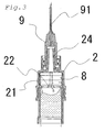
- Fig. 3 is a view showing a state in which the pre-filled syringe is being shaken for dissolution and operation positions of the front end and intermediate gaskets
- Fig. 1 is a cross-sectional view of the same
- Figs. 2 - 4 are longitudinal sectional views explaining a use of the pre-filled syringe of the first embodiment.
- Fig. 2 is a view showing a state before dissolution is performed and position of the front end gasket
- Fig. 3 is a view showing a
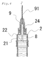
- FIG. 4 is a view showing a state in which air bubbles are being discharged during preparation for injection and operation positions of the front end and intermediate gaskets.
- Fig. 5 is a cross-sectional view showing a one-chamber type pre-filled syringe that is a second embodiment of the present invention.
- a pre-filled syringe A that is one implementation mode of the present invention has, among the above characteristics, (1), (2), (3) and (5), and additionally it is desirable to have characteristic (4).
- the pre-filled syringe A is a two-chamber type pre-filled syringe possessing a barrel 1 whose front end and base end are open, an intermediate gasket 6 fluid-tightly partitioning an inside of the barrel 1 into a front chamber and a rear chamber, a base end gasket 4 in a base end side relative to intermediate gasket 6 and sealing the inside of the barrel 1, a plunger rod 12 connected to a base end of the base end gasket 4, a front end gasket 8 placed in a front end side relative to the intermediate gasket 6 and sealing the inside of the barrel 1, a nozzle member 2 which is fluid-tightly engaged with a front end of the barrel 1 and to which an injection needle 9 is detachably attached, and a flange part 3
- the nozzle member 2 is a tubular member whose front end has a nozzle 24 capable of discharging a liquid medicine LD and a base end that is open and to which the barrel 1 can be fluid-tightly fitted. And, in its inside, there is formed the front end gasket accommodation part 23 which is capable of accommodating the front end gasket 8, which is mentioned later. Further, as shown in Fig. 2 , in an inner wall of the front end gasket accommodation part 23, there is formed liquid flow passage 21 through which the liquid medicine LD can pass when the front end gasket 8 has been accommodated in the front end gasket accommodation part 23.
- This liquid flow passage 21 is a groove having been concavely provided in a side wall and a top face of the front end gasket accommodation part 23, and its one end is connected to an inner cavity of the nozzle 24 and the other end can communicate with the barrel 1.
- an axial length of the liquid flow passage 21 must be longer than an axial length of the front end gasket 8 and, if it is shorter, it is impossible to discharge the liquid medicine LD.
- the liquid flow passage 21 possesses a wide width part 22 in which a width widens in a base end of the side wall such that a sectional area of the front end becomes smaller than that of the base end of the side wall when seen in the sectional area of the front end of the side wall.
- the nozzle 24 can be a male luer to which the injection needle 9 can be connected.
- the material for forming the nozzle member 2 although there are enumerated, e.g., polyolefin resins such as polyethylene and polypropylene, polyvinyl chloride, PET (polyethylene terephthalate), EVA (ethylene-vinyl acetate copolymer), EVOH (ethylene-vinyl alcohol copolymer), polyamide, polyvinylidene chloride, polyvinyl fluoride, poly-trifluorochloroethylene, polyester, nylon, mixtures thereof and laminated bodies thereof, the material is not limited especially if it is known for use as a medical equipment material and does not interact with the medicine accommodated in the barrel 1, and also there is no fear of elution into the medicine or the like.
- polyolefin resins such as polyethylene and polypropylene, polyvinyl chloride, PET (polyethylene terephthalate), EVA (ethylene-vinyl acetate copolymer), EVOH (ethylene-vinyl alcohol copolymer), polyamide
- the injection nozzle 9 is generally attached to the nozzle 24.
- a needle protector 10 is mounted on the injection needle 9.
- the material for forming the needle protector 10 is not limited, especially if it is known for use as a medical equipment material and has a rigidity which prevents fear that the injection needle 9 will be bent or damaged by a load from the outside.
- a cap (not shown in the drawing) is used to seal the nozzle 24.
- an elastic material such as, e.g., butyl rubber, silicone rubber, a thermoplastic elastomer and a silicone elastomer, the material is not limited especially if it is known for use as a medical equipment material and can seal the nozzle 24.
- the barrel 1 is a tubular member whose front end and base end are open and the flange part 3 for applying fingers is formed at its base end, and its front end is fluid-tightly mounted to the nozzle member 2.
- the front end of the barrel 1 is fluid-tightly sealed by the front end gasket 8, and the base end is fluid-tightly sealed by the base end gasket 4.
- the intermediate gasket 6 is inserted into the barrel 1, and the inside of the barrel 1 is fluid-tightly partitioned into a front chamber 7 and a rear chamber 5 by the intermediate gasket 6. Additionally, in a wall of the front chamber 7, the bypass 11 is formed in the axial direction of the barrel 1 so as to bulge radially outward.
- the material for forming the barrel 1 although there are enumerated, e.g., glass, polyolefin resins such as polyethylene and polypropylene, polyvinyl chloride, PET (polyethylene terephthalate), EVA (ethylene-vinyl acetate copolymer), EVOH (ethylene-vinyl alcohol copolymer), polyamide, polyvinylidene chloride, polyvinyl fluoride, poly-trifluorochloroethylene, polyester, nylon, mixtures thereof and laminated bodies thereof, the material is not limited especially if it is known for use as a medical equipment material and does not interact with the medicine accommodated in the barrel 1, and also there is no fear of elution into the medicine or the like.
- polyolefin resins such as polyethylene and polypropylene, polyvinyl chloride, PET (polyethylene terephthalate), EVA (ethylene-vinyl acetate copolymer), EVOH (ethylene-vinyl alcohol copolymer), polyamide
- a solution L is accommodated in the rear chamber 5. It is desirable that, as the solution accommodated in the rear chamber 5, there is accommodated a solution like physiological salt solution and glucose solution, or a liquid chemical as a liquid medicine.
- a powder medicine M is accommodated in the front chamber 7.
- a form of the medicine accommodated in the front chamber 7 is not especially limited, and it may be a liquid-like medicine which is necessary to be mixed just before use.
- the front end gasket 8, the base end gasket 4 and the intermediate gasket 6 are all columnar members consisting of an elastic body and have several annular ribs 41, 61, 81 formed in their side faces in a circumferential direction for fluid-tightly contacting with the inner wall of the barrel 1, and are slidable in the barrel 1. Further, as shown in Fig.
- the ribs of the intermediate gasket 6 may include an annular rib 61 formed in the front end side in the circumferential direction for fluid-tightly contacting the inner wall of the barrel 1, a circumferential groove 62 concavely provided in the circumferential direction while adjoining a base end side of the annular rib 61, and a spiral communication passage 63 communicating the circumferential groove 62 with the rear chamber 5.
- an inner pressure of the front chamber 7 is raised by an advance of the intermediate gasket 6 in preparation for dissolution and thus the inside of the front chamber 7 becomes like a compressed air spring and, when the solution L flows into the front chamber 7 through the bypass 11, the front end gasket 8 vigorously moves forward and enters to the front end gasket accommodation part 23, so that there is an advantage that the liquid medicine LD is prevented from flying out by its vigorous power from a needle tip 91 of the injection needle 9.
- annular rib 61 by suitably setting lengths of the annular rib 61, the circumferential groove 62, the communication passage 63 and the base end gasket 4, since it is possible to avoid a fear that, when the liquid medicine LD in the pre-filled syringe has been wholly discharged, an annular rib 42 existing in a most base end of the base end gasket 4 moves forward beyond a base end of the bypass 11, it is possible to prevent the liquid medicine LD from leaking to the outside from a base end side of the barrel 1 in a case of a liquid medicine whose toxicity is strong, or the like.
- an elastic material such as, e.g., butyl rubber, silicone rubber, a thermoplastic elastomer and a silicone elastomer
- the material is not limited especially if it is known for the use performance as a medical equipment material, and generates no interaction with the medicine accommodated in the barrel 1.
- a plunger rod 12 is connected to the base end of the base end gasket 4.
- the plunger rod 12 may be previously connected, or may be connected at a time of use.
- As a connection method there are enumerated fitting engagement, meshing engagement and the like.
- the pre-filled syringe A of the first embodiment Fig. 1
- the pre-filled syringe A is placed in a state that the injection needle 91 is directed upward. If the plunger rod 12 is pushed and moved forward in a front end direction while supporting the flange part 3 by the fingers, the inner pressure of the rear chamber 5 is raised and, accompanying it, the intermediate gasket 6 is also moved forward.
- the pre-filled syringe is shaken with an amount of force complying with a dispersion property of the powder medicine M, thereby dissolving the powder medicine M in the liquid chemical L and making the liquid medicine LD.
- a liquid surface ruffles during shaking time and, even if the liquid medicine enters between an inner periphery wall of the front end gasket accommodation part 23 and a side face of the front end gasket 8 when dissolution is insufficient, it immediately returns into the front chamber 7.
- the needle protector 10 is removed and the needle tip 91 of the injection needle is pierced into an object portion of a patient, and the plunger rod 12 is slowly pushed, thereby injecting the liquid medicine LD. From this state, if the plunger rod 12 is additionally strongly pushed, the front end, the intermediate and the base end gaskets 4, 6 and 8 are elastically deformed respectively, so that it is possible to inject the liquid medicine LD in the pre-filled syringe A without leaving the medicine in the syringe.
- a pre-filled syringe B that is another embodiment of the present invention has, among the above characteristics, (2) and (3), and additionally it is desirable to have (4).
- the pre-filled syringe B is a one-chamber type pre-filled syringe including a barrel 1 whose front end and base end are open, a base end gasket 4 fluid-tightly and slidably attached to a base end in the barrel 1, a plunger rod 12 connected to the base end of a base end gasket 4, the front end gasket 8 fluid-tightly and slidably attached to the front end in the barrel 1, a nozzle member 2 which is fluid-tightly engaged with the front end of the barrel 1 and to which the injection needle 9 is detachably attached, and a flange part 3 provided at the base end part of the barrel 1.
- Pre-filled syringe B comprises a construction in which the nozzle member 2 includes the front end gasket accommodation part 23 capable of accommodating the front end gasket 8, at least two liquid flow passages 21 extending in the axial direction in the inner periphery wall, through which the liquid medicine can pass when the front end gasket 8 is accommodated in the front end gasket accommodation part 23, and a wide width part 22 of the liquid flow passage, in which the sectional area in the front end of the liquid flow passage becomes smaller than the sectional area of the base end.
- the nozzle member 2 is a tubular member whose front end has a nozzle 24 capable of discharging a liquid medicine LD and base end which is opened and to which the barrel 1 can be fluid-tightly fitted. And, in its inside, there is formed the front end gasket accommodation part 23 which is capable of accommodating the front end gasket 8, which is mentioned later. Further, as shown in Fig.5 , in the inner wall of the front end gasket accommodation part 23, there is formed the liquid flow passage 21 through which the liquid medicine LD can pass when the front end gasket 8 has been accommodated in the front end gasket accommodation part 23.
- This liquid flow passage 21 is a groove concavely provided in the side wall and the top face of the front end gasket accommodation part 23, and its one end is linked to the inner cavity of the nozzle 24 and the other end can communicate with the barrel 1 .
- the axial length of the liquid flow passage 21 must be longer than the axial length of the front end gasket 8. If it is shorter, it is impossible to discharge the liquid medicine LD.
- the liquid flow passage 21 possesses wide width part 22 in which the width widens in the base end of the side wall such that a sectional area of the front end becomes smaller than that of the base end of the side wall when seen in a sectional area of the front end of the side wall.
- the nozzle 24 can be in the form of a male luer to which the injection needle 9 can be connected.
- the material for forming the nozzle member 2 although there can be enumerated, e.g., polyolefin resins such as polyethylene and polypropylene, polyvinyl chloride, PET (polyethylene terephthalate), EVA (ethylene-vinyl acetate copolymer), EVOH (ethylene-vinyl alcohol copolymer), polyamide, polyvinylidene chloride, polyvinyl fluoride, poly-trifluorochloroethylene, polyester, nylon, mixtures thereof and laminated bodies thereof, the material is not limited especially if it is known for use as a medical equipment material and does not interact with the medicine accommodated in the barrel 1, and also if there is no fear of elution of the material into the medicine or the like.
- the nozzle member 2 can also be a nozzle part which is formed as one body with the barrel 1.
- the injection nozzle 9 is generally attached to the nozzle 24.
- the needle protector 10 is mounted on the injection needle 9.
- the material for forming the needle protector 10 the material is not especially limited if it is known for use as a medical equipment material, and has a rigidity which prevent a fear of the injection needle being bent or damaged by a load from the outside.
- a cap (not shown in the drawing) is used to seal the nozzle 24.
- an elastic material such as, e.g., butyl rubber, silicone rubber, a thermoplastic elastomer and a silicone elastomer, the material is not limited especially if it is known for use as a medical equipment material and can seal the nozzle 24.
- the barrel 1 is a tubular member whose front end and base end are open and has flange part 3 for applying fingers formed at its base end and has nozzle member 2 fluid-tightly mounted to its front end.
- the front end of the barrel 1 is fluid-tightly sealed by the front end gasket 8, and the base end is fluid-tightly sealed by the base end gasket 4, thereby forming a liquid medicine chamber 5.
- the material for forming the barrel 1 although there can be enumerated, e.g., glass, polyolefin resins such as polyethylene and polypropylene, polyvinyl chloride, PET (polyethylene terephthalate), EVA (ethylene-vinyl acetate copolymer), EVOH (ethylene-vinyl alcohol copolymer), polyamide, polyvinylidene chloride, polyvinyl fluoride, poly-trifluorochloroethylene, polyester, nylon, mixtures thereof and laminated bodies thereof, the material is not limited especially if it is known for use as a medical equipment material and does not interact with the medicine accommodated in the barrel 1, and also if there is no fear of elution of the material into the medicine or the like.
- polyolefin resins such as polyethylene and polypropylene, polyvinyl chloride, PET (polyethylene terephthalate), EVA (ethylene-vinyl acetate copolymer), EVOH (ethylene-vinyl alcohol cop
- the liquid medicine LD is accommodated in the liquid medicine chamber 5.
- the front end gasket 8 and the base end gasket 4 are all columnar members consisting of an elastic body, have several annular ribs 41, 81 formed in their side faces in the circumferential direction while fluid-tightly contacting the inner wall of the barrel 1, and are slidable in the barrel 1.
- an elastic material such as, e.g., butyl rubber, silicone rubber, thermoplastic elastomer and a silicone elastomer
- the raw material thereof is not limited especially if it is known for use as a medical equipment material, and generates no interaction with the medicine accommodated in the barrel 1.
- the plunger rod 12 is connected to the base end of the base end gasket 4.
- the plunger rod 12 may be previously connected, or may be connected at the time of use.
- As the connection method there are enumerated fitting engagement, meshing engagement and the like.
- the needle protector 10 is removed and the needle tip 91 of the injection needle is pierced into an object portion of a patient, and the plunger rod 12 is slowly pushed, thereby injecting the liquid medicine LD.
Landscapes
- Health & Medical Sciences (AREA)
- Vascular Medicine (AREA)
- Engineering & Computer Science (AREA)
- Anesthesiology (AREA)
- Biomedical Technology (AREA)
- Heart & Thoracic Surgery (AREA)
- Hematology (AREA)
- Life Sciences & Earth Sciences (AREA)
- Animal Behavior & Ethology (AREA)
- General Health & Medical Sciences (AREA)
- Public Health (AREA)
- Veterinary Medicine (AREA)
- Infusion, Injection, And Reservoir Apparatuses (AREA)
Applications Claiming Priority (1)
| Application Number | Priority Date | Filing Date | Title |
|---|---|---|---|
| JP2006005430A JP4682850B2 (ja) | 2006-01-12 | 2006-01-12 | プレフィルドシリンジ |
Publications (2)
| Publication Number | Publication Date |
|---|---|
| EP1808192A1 EP1808192A1 (en) | 2007-07-18 |
| EP1808192B1 true EP1808192B1 (en) | 2015-12-30 |
Family
ID=37846974
Family Applications (1)
| Application Number | Title | Priority Date | Filing Date |
|---|---|---|---|
| EP07000079.9A Active EP1808192B1 (en) | 2006-01-12 | 2007-01-03 | Pre-filled syringe |
Country Status (4)
| Country | Link |
|---|---|
| US (1) | US7699811B2 (es) |
| EP (1) | EP1808192B1 (es) |
| JP (1) | JP4682850B2 (es) |
| ES (1) | ES2562244T3 (es) |
Families Citing this family (25)
| Publication number | Priority date | Publication date | Assignee | Title |
|---|---|---|---|---|
| US8152778B2 (en) * | 2008-09-30 | 2012-04-10 | Tyco Healthcare Group Lp | Device for interfacing with standard luer lock syringes |
| EP2358392B1 (en) | 2008-11-12 | 2019-01-09 | MedImmune, LLC | Antibody formulation |
| EP2581102A4 (en) * | 2010-06-11 | 2013-11-20 | Nipro Corp | PRE-FILLED SYRINGE |
| WO2012022734A2 (en) | 2010-08-16 | 2012-02-23 | Medimmune Limited | Anti-icam-1 antibodies and methods of use |
| JP4934226B1 (ja) * | 2011-02-02 | 2012-05-16 | 株式会社アルテ | 容器兼用注射器 |
| WO2012170540A2 (en) * | 2011-06-07 | 2012-12-13 | Actitech, L.P. | Apparatus and method for steam disinfection of a powder |
| US9181572B2 (en) | 2012-04-20 | 2015-11-10 | Abbvie, Inc. | Methods to modulate lysine variant distribution |
| WO2013176754A1 (en) | 2012-05-24 | 2013-11-28 | Abbvie Inc. | Novel purification of antibodies using hydrophobic interaction chromatography |
| CA2890933C (en) | 2012-12-03 | 2021-06-08 | Novobiotic Pharmaceuticals, Llc | Novel depsipeptide and uses thereof |
| JP5437510B1 (ja) * | 2013-02-15 | 2014-03-12 | 株式会社アルテ | 二室式容器兼用注射器 |
| AU2014240431A1 (en) | 2013-03-14 | 2015-08-27 | Abbvie Inc. | Low acidic species compositions and methods for producing the same using displacement chromatography |
| AU2013384204B2 (en) | 2013-03-14 | 2017-03-16 | Abbvie Inc. | Low acidic species compositions and methods for producing and using the same |
| WO2015006460A1 (en) | 2013-07-10 | 2015-01-15 | Matrix Biology Institute | Compositions of hyaluronan with high elasticity and uses thereof |
| ES2878019T3 (es) * | 2013-09-10 | 2021-11-18 | Augma Biomaterials Ltd | Aplicador de componente doble |
| WO2015050959A1 (en) | 2013-10-01 | 2015-04-09 | Yale University | Anti-kit antibodies and methods of use thereof |
| EP3075403B1 (en) | 2013-11-27 | 2018-09-19 | Nipro Corporation | Pre-filled syringe |
| US20170226552A1 (en) | 2014-07-03 | 2017-08-10 | Abbvie Inc. | Methods for modulating protein glycosylation profiles of recombinant protein therapeutics using cobalt |
| WO2016007764A1 (en) | 2014-07-09 | 2016-01-14 | Abbvie Inc. | Methods for modulating the glycosylation profile of recombinant proteins using non-commonly used sugars |
| CN107205843B (zh) | 2014-12-08 | 2020-02-28 | 豪夫迈·罗氏有限公司 | 通用的注射器平台 |
| WO2016144773A1 (en) | 2015-03-06 | 2016-09-15 | Abbvie Inc. | Arabinosylated glycoproteins |
| DE102015206757A1 (de) * | 2015-04-15 | 2016-10-20 | Henkel IP & Holding GmbH | Misch- und Ausgabevorrichtung sowie Verfahren für die Bereitstellung und Applikation eines aus mindestens zwei Komponenten bestehenden Klebstoffes |
| EP3352766B1 (en) | 2015-09-24 | 2021-03-17 | Matrix Biology Institute | High elasticity hyaluronan compositions and methods of use thereof |
| WO2017147003A1 (en) | 2016-02-26 | 2017-08-31 | Novobiotic Pharmaceuticals, Llc | Novel macrocyclic antibiotics and uses thereof |
| CA3057987A1 (en) | 2017-04-04 | 2018-10-11 | Novobiotic Pharmaceuticals, Llc | Novel depsipeptides and uses thereof |
| BE1026618B1 (nl) * | 2019-03-15 | 2020-04-08 | Hubert De Backer Nv | Injectiespuit met ontluchtingskanalen |
Family Cites Families (16)
| Publication number | Priority date | Publication date | Assignee | Title |
|---|---|---|---|---|
| NL180634C (nl) | 1977-12-23 | 1987-04-01 | Duphar Int Res | Injectiespuit alsmede naaldhouder hiervoor. |
| EP0072057B1 (en) * | 1981-08-10 | 1988-02-10 | Duphar International Research B.V | Automatic injection syringe |
| ATE42041T1 (de) * | 1985-02-07 | 1989-04-15 | Duphar Int Res | Injektionsspritze. |
| DE3674483D1 (de) * | 1985-06-27 | 1990-10-31 | Duphar Int Res | Mehrkammerspritze. |
| JP3419925B2 (ja) * | 1994-11-18 | 2003-06-23 | 株式会社アルテ | 1室式容器兼用注射器 |
| JPH09225032A (ja) * | 1995-12-22 | 1997-09-02 | Material Eng Tech Lab Inc | 注射器 |
| KR100373886B1 (ko) * | 1996-09-10 | 2003-02-26 | 데츠로 히가시카와 | 주사기용 미끄럼이동 밸브, 주사기, 및 키트제제 |
| JP4046152B2 (ja) | 1998-11-30 | 2008-02-13 | 日本電波工業株式会社 | 眼科用の超音波探触子 |
| JP2001112867A (ja) * | 1999-10-18 | 2001-04-24 | Terumo Corp | 薬剤入りシリンジ |
| US6966897B2 (en) * | 2000-09-22 | 2005-11-22 | Arte Corporation | Combined container-syringe and assembly method of the same |
| JP4626064B2 (ja) * | 2000-09-28 | 2011-02-02 | 生化学工業株式会社 | 注射器 |
| JP2002177391A (ja) | 2000-12-13 | 2002-06-25 | Arute:Kk | 容器兼用注射器 |
| JP4098593B2 (ja) * | 2002-10-08 | 2008-06-11 | 株式会社アルテ | 容器兼用注射器 |
| US6866653B2 (en) * | 2002-10-31 | 2005-03-15 | Kyongtae T. Bae | Method and apparatus for sequential delivery of multiple injectable substances stored in a prefilled syringe |
| ES2416311T3 (es) | 2004-03-23 | 2013-07-31 | Nipro Corporation | Jeringuilla prellenada |
| JP4641819B2 (ja) * | 2004-05-06 | 2011-03-02 | 一般財団法人化学及血清療法研究所 | プレフィルドシリンジ |
-
2006
- 2006-01-12 JP JP2006005430A patent/JP4682850B2/ja active Active
-
2007
- 2007-01-03 ES ES07000079.9T patent/ES2562244T3/es active Active
- 2007-01-03 EP EP07000079.9A patent/EP1808192B1/en active Active
- 2007-01-11 US US11/652,001 patent/US7699811B2/en active Active
Also Published As
| Publication number | Publication date |
|---|---|
| US7699811B2 (en) | 2010-04-20 |
| JP4682850B2 (ja) | 2011-05-11 |
| ES2562244T3 (es) | 2016-03-03 |
| EP1808192A1 (en) | 2007-07-18 |
| US20070161961A1 (en) | 2007-07-12 |
| JP2007185319A (ja) | 2007-07-26 |
Similar Documents
| Publication | Publication Date | Title |
|---|---|---|
| EP1808192B1 (en) | Pre-filled syringe | |
| JP2007185319A5 (es) | ||
| EP1728528B1 (en) | Pre-filled syringe | |
| EP1592381B1 (en) | Pharmaceutical delivery systems | |
| CN107771093B (zh) | 用于混合两种组分和用于在存储条件下保持真空的注射器 | |
| EP1093826A1 (en) | Pre-filled syringe | |
| KR102372700B1 (ko) | 프리필드 시린지 | |
| EP2814446A1 (en) | Fluid transfer devices having cartridge port with cartridge ejection arrangement | |
| JPS6258745B2 (es) | ||
| US20160184571A1 (en) | Prefilled Syringe Devices Employing Microneedle Interfaces for Intradermal Delivery | |
| US10130771B2 (en) | Syringe barrel and mold for injection molding | |
| WO2016153003A1 (ja) | 医療用樹脂製中空針、穿刺部付外筒およびプレフィルドシリンジ | |
| JP2017522115A (ja) | 事前充填注射器 | |
| EP2922589B1 (en) | Valve permitting mixing in a drug delivery device | |
| EP0728492A2 (en) | Dual chamber internal by-pass syringe assembly | |
| WO2017057476A1 (ja) | 医療用樹脂製中空針、それを用いた医療用具セットおよび穿刺部付外筒 | |
| JP2003528699A (ja) | プレフィルドカートリッジを備えた無針シリンジ | |
| JP4114197B2 (ja) | プレフィルドシリンジキット |
Legal Events
| Date | Code | Title | Description |
|---|---|---|---|
| PUAI | Public reference made under article 153(3) epc to a published international application that has entered the european phase |
Free format text: ORIGINAL CODE: 0009012 |
|
| AK | Designated contracting states |
Kind code of ref document: A1 Designated state(s): AT BE BG CH CY CZ DE DK EE ES FI FR GB GR HU IE IS IT LI LT LU LV MC NL PL PT RO SE SI SK TR |
|
| AX | Request for extension of the european patent |
Extension state: AL BA HR MK YU |
|
| 17P | Request for examination filed |
Effective date: 20080103 |
|
| 17Q | First examination report despatched |
Effective date: 20080214 |
|
| AKX | Designation fees paid |
Designated state(s): AT BE BG CH CY CZ DE DK EE ES FI FR GB GR HU IE IS IT LI LT LU LV MC NL PL PT RO SE SI SK TR |
|
| RIC1 | Information provided on ipc code assigned before grant |
Ipc: A61M 5/315 20060101ALN20150529BHEP Ipc: A61M 5/31 20060101AFI20150529BHEP Ipc: A61M 5/28 20060101ALN20150529BHEP |
|
| GRAP | Despatch of communication of intention to grant a patent |
Free format text: ORIGINAL CODE: EPIDOSNIGR1 |
|
| RAP1 | Party data changed (applicant data changed or rights of an application transferred) |
Owner name: NIPRO CORPORATION |
|
| INTG | Intention to grant announced |
Effective date: 20150715 |
|
| GRAS | Grant fee paid |
Free format text: ORIGINAL CODE: EPIDOSNIGR3 |
|
| GRAA | (expected) grant |
Free format text: ORIGINAL CODE: 0009210 |
|
| REG | Reference to a national code |
Ref country code: FR Ref legal event code: PLFP Year of fee payment: 10 |
|
| AK | Designated contracting states |
Kind code of ref document: B1 Designated state(s): AT BE BG CH CY CZ DE DK EE ES FI FR GB GR HU IE IS IT LI LT LU LV MC NL PL PT RO SE SI SK TR |
|
| REG | Reference to a national code |
Ref country code: GB Ref legal event code: FG4D |
|
| REG | Reference to a national code |
Ref country code: CH Ref legal event code: EP |
|
| REG | Reference to a national code |
Ref country code: AT Ref legal event code: REF Ref document number: 767170 Country of ref document: AT Kind code of ref document: T Effective date: 20160115 |
|
| REG | Reference to a national code |
Ref country code: IE Ref legal event code: FG4D |
|
| REG | Reference to a national code |
Ref country code: DE Ref legal event code: R096 Ref document number: 602007044345 Country of ref document: DE |
|
| REG | Reference to a national code |
Ref country code: ES Ref legal event code: FG2A Ref document number: 2562244 Country of ref document: ES Kind code of ref document: T3 Effective date: 20160303 |
|
| REG | Reference to a national code |
Ref country code: LT Ref legal event code: MG4D |
|
| PG25 | Lapsed in a contracting state [announced via postgrant information from national office to epo] |
Ref country code: LT Free format text: LAPSE BECAUSE OF FAILURE TO SUBMIT A TRANSLATION OF THE DESCRIPTION OR TO PAY THE FEE WITHIN THE PRESCRIBED TIME-LIMIT Effective date: 20151230 |
|
| REG | Reference to a national code |
Ref country code: NL Ref legal event code: MP Effective date: 20151230 |
|
| REG | Reference to a national code |
Ref country code: AT Ref legal event code: MK05 Ref document number: 767170 Country of ref document: AT Kind code of ref document: T Effective date: 20151230 |
|
| PG25 | Lapsed in a contracting state [announced via postgrant information from national office to epo] |
Ref country code: GR Free format text: LAPSE BECAUSE OF FAILURE TO SUBMIT A TRANSLATION OF THE DESCRIPTION OR TO PAY THE FEE WITHIN THE PRESCRIBED TIME-LIMIT Effective date: 20160331 Ref country code: LV Free format text: LAPSE BECAUSE OF FAILURE TO SUBMIT A TRANSLATION OF THE DESCRIPTION OR TO PAY THE FEE WITHIN THE PRESCRIBED TIME-LIMIT Effective date: 20151230 Ref country code: BE Free format text: LAPSE BECAUSE OF NON-PAYMENT OF DUE FEES Effective date: 20160131 Ref country code: FI Free format text: LAPSE BECAUSE OF FAILURE TO SUBMIT A TRANSLATION OF THE DESCRIPTION OR TO PAY THE FEE WITHIN THE PRESCRIBED TIME-LIMIT Effective date: 20151230 Ref country code: SE Free format text: LAPSE BECAUSE OF FAILURE TO SUBMIT A TRANSLATION OF THE DESCRIPTION OR TO PAY THE FEE WITHIN THE PRESCRIBED TIME-LIMIT Effective date: 20151230 |
|
| PG25 | Lapsed in a contracting state [announced via postgrant information from national office to epo] |
Ref country code: NL Free format text: LAPSE BECAUSE OF FAILURE TO SUBMIT A TRANSLATION OF THE DESCRIPTION OR TO PAY THE FEE WITHIN THE PRESCRIBED TIME-LIMIT Effective date: 20151230 |
|
| PG25 | Lapsed in a contracting state [announced via postgrant information from national office to epo] |
Ref country code: CZ Free format text: LAPSE BECAUSE OF FAILURE TO SUBMIT A TRANSLATION OF THE DESCRIPTION OR TO PAY THE FEE WITHIN THE PRESCRIBED TIME-LIMIT Effective date: 20151230 |
|
| PG25 | Lapsed in a contracting state [announced via postgrant information from national office to epo] |
Ref country code: PL Free format text: LAPSE BECAUSE OF FAILURE TO SUBMIT A TRANSLATION OF THE DESCRIPTION OR TO PAY THE FEE WITHIN THE PRESCRIBED TIME-LIMIT Effective date: 20151230 Ref country code: AT Free format text: LAPSE BECAUSE OF FAILURE TO SUBMIT A TRANSLATION OF THE DESCRIPTION OR TO PAY THE FEE WITHIN THE PRESCRIBED TIME-LIMIT Effective date: 20151230 Ref country code: IS Free format text: LAPSE BECAUSE OF FAILURE TO SUBMIT A TRANSLATION OF THE DESCRIPTION OR TO PAY THE FEE WITHIN THE PRESCRIBED TIME-LIMIT Effective date: 20160430 Ref country code: PT Free format text: LAPSE BECAUSE OF FAILURE TO SUBMIT A TRANSLATION OF THE DESCRIPTION OR TO PAY THE FEE WITHIN THE PRESCRIBED TIME-LIMIT Effective date: 20160502 Ref country code: LU Free format text: LAPSE BECAUSE OF FAILURE TO SUBMIT A TRANSLATION OF THE DESCRIPTION OR TO PAY THE FEE WITHIN THE PRESCRIBED TIME-LIMIT Effective date: 20160103 Ref country code: EE Free format text: LAPSE BECAUSE OF FAILURE TO SUBMIT A TRANSLATION OF THE DESCRIPTION OR TO PAY THE FEE WITHIN THE PRESCRIBED TIME-LIMIT Effective date: 20151230 Ref country code: RO Free format text: LAPSE BECAUSE OF FAILURE TO SUBMIT A TRANSLATION OF THE DESCRIPTION OR TO PAY THE FEE WITHIN THE PRESCRIBED TIME-LIMIT Effective date: 20151230 Ref country code: SK Free format text: LAPSE BECAUSE OF FAILURE TO SUBMIT A TRANSLATION OF THE DESCRIPTION OR TO PAY THE FEE WITHIN THE PRESCRIBED TIME-LIMIT Effective date: 20151230 |
|
| REG | Reference to a national code |
Ref country code: CH Ref legal event code: PL |
|
| PG25 | Lapsed in a contracting state [announced via postgrant information from national office to epo] |
Ref country code: MC Free format text: LAPSE BECAUSE OF FAILURE TO SUBMIT A TRANSLATION OF THE DESCRIPTION OR TO PAY THE FEE WITHIN THE PRESCRIBED TIME-LIMIT Effective date: 20151230 |
|
| REG | Reference to a national code |
Ref country code: DE Ref legal event code: R097 Ref document number: 602007044345 Country of ref document: DE |
|
| PG25 | Lapsed in a contracting state [announced via postgrant information from national office to epo] |
Ref country code: DK Free format text: LAPSE BECAUSE OF FAILURE TO SUBMIT A TRANSLATION OF THE DESCRIPTION OR TO PAY THE FEE WITHIN THE PRESCRIBED TIME-LIMIT Effective date: 20151230 Ref country code: LI Free format text: LAPSE BECAUSE OF NON-PAYMENT OF DUE FEES Effective date: 20160131 Ref country code: CH Free format text: LAPSE BECAUSE OF NON-PAYMENT OF DUE FEES Effective date: 20160131 |
|
| REG | Reference to a national code |
Ref country code: IE Ref legal event code: MM4A |
|
| PLBE | No opposition filed within time limit |
Free format text: ORIGINAL CODE: 0009261 |
|
| STAA | Information on the status of an ep patent application or granted ep patent |
Free format text: STATUS: NO OPPOSITION FILED WITHIN TIME LIMIT |
|
| 26N | No opposition filed |
Effective date: 20161003 |
|
| PG25 | Lapsed in a contracting state [announced via postgrant information from national office to epo] |
Ref country code: BE Free format text: LAPSE BECAUSE OF FAILURE TO SUBMIT A TRANSLATION OF THE DESCRIPTION OR TO PAY THE FEE WITHIN THE PRESCRIBED TIME-LIMIT Effective date: 20151230 |
|
| REG | Reference to a national code |
Ref country code: FR Ref legal event code: PLFP Year of fee payment: 11 |
|
| PG25 | Lapsed in a contracting state [announced via postgrant information from national office to epo] |
Ref country code: IE Free format text: LAPSE BECAUSE OF NON-PAYMENT OF DUE FEES Effective date: 20160103 |
|
| PG25 | Lapsed in a contracting state [announced via postgrant information from national office to epo] |
Ref country code: SI Free format text: LAPSE BECAUSE OF FAILURE TO SUBMIT A TRANSLATION OF THE DESCRIPTION OR TO PAY THE FEE WITHIN THE PRESCRIBED TIME-LIMIT Effective date: 20151230 Ref country code: IT Free format text: LAPSE BECAUSE OF NON-PAYMENT OF DUE FEES Effective date: 20160103 |
|
| PG25 | Lapsed in a contracting state [announced via postgrant information from national office to epo] |
Ref country code: IT Free format text: LAPSE BECAUSE OF NON-PAYMENT OF DUE FEES Effective date: 20160103 |
|
| PGRI | Patent reinstated in contracting state [announced from national office to epo] |
Ref country code: IT Effective date: 20170710 |
|
| REG | Reference to a national code |
Ref country code: FR Ref legal event code: PLFP Year of fee payment: 12 |
|
| PG25 | Lapsed in a contracting state [announced via postgrant information from national office to epo] |
Ref country code: CY Free format text: LAPSE BECAUSE OF FAILURE TO SUBMIT A TRANSLATION OF THE DESCRIPTION OR TO PAY THE FEE WITHIN THE PRESCRIBED TIME-LIMIT Effective date: 20151230 Ref country code: HU Free format text: LAPSE BECAUSE OF FAILURE TO SUBMIT A TRANSLATION OF THE DESCRIPTION OR TO PAY THE FEE WITHIN THE PRESCRIBED TIME-LIMIT; INVALID AB INITIO Effective date: 20070103 |
|
| PG25 | Lapsed in a contracting state [announced via postgrant information from national office to epo] |
Ref country code: TR Free format text: LAPSE BECAUSE OF FAILURE TO SUBMIT A TRANSLATION OF THE DESCRIPTION OR TO PAY THE FEE WITHIN THE PRESCRIBED TIME-LIMIT Effective date: 20151230 |
|
| PG25 | Lapsed in a contracting state [announced via postgrant information from national office to epo] |
Ref country code: BG Free format text: LAPSE BECAUSE OF FAILURE TO SUBMIT A TRANSLATION OF THE DESCRIPTION OR TO PAY THE FEE WITHIN THE PRESCRIBED TIME-LIMIT Effective date: 20151230 |
|
| PGFP | Annual fee paid to national office [announced via postgrant information from national office to epo] |
Ref country code: FR Payment date: 20230124 Year of fee payment: 17 |
|
| PGFP | Annual fee paid to national office [announced via postgrant information from national office to epo] |
Ref country code: IT Payment date: 20230120 Year of fee payment: 17 |
|
| PGFP | Annual fee paid to national office [announced via postgrant information from national office to epo] |
Ref country code: ES Payment date: 20240223 Year of fee payment: 18 |
|
| PGFP | Annual fee paid to national office [announced via postgrant information from national office to epo] |
Ref country code: DE Payment date: 20240119 Year of fee payment: 18 Ref country code: GB Payment date: 20240119 Year of fee payment: 18 |