EP1805409B1 - Magnetventilbetätigter kraftstoffinjektor mit hydraulischem überhubanschlag - Google Patents
Magnetventilbetätigter kraftstoffinjektor mit hydraulischem überhubanschlag Download PDFInfo
- Publication number
- EP1805409B1 EP1805409B1 EP05801500A EP05801500A EP1805409B1 EP 1805409 B1 EP1805409 B1 EP 1805409B1 EP 05801500 A EP05801500 A EP 05801500A EP 05801500 A EP05801500 A EP 05801500A EP 1805409 B1 EP1805409 B1 EP 1805409B1
- Authority
- EP
- European Patent Office
- Prior art keywords
- armature
- solenoid valve
- plate
- valve according
- bolt
- Prior art date
- Legal status (The legal status is an assumption and is not a legal conclusion. Google has not performed a legal analysis and makes no representation as to the accuracy of the status listed.)
- Expired - Lifetime
Links
Images
Classifications
-
- F—MECHANICAL ENGINEERING; LIGHTING; HEATING; WEAPONS; BLASTING
- F02—COMBUSTION ENGINES; HOT-GAS OR COMBUSTION-PRODUCT ENGINE PLANTS
- F02M—SUPPLYING COMBUSTION ENGINES IN GENERAL WITH COMBUSTIBLE MIXTURES OR CONSTITUENTS THEREOF
- F02M63/00—Other fuel-injection apparatus having pertinent characteristics not provided for in groups F02M39/00 - F02M57/00 or F02M67/00; Details, component parts, or accessories of fuel-injection apparatus, not provided for in, or of interest apart from, the apparatus of groups F02M39/00 - F02M61/00 or F02M67/00; Combination of fuel pump with other devices, e.g. lubricating oil pump
- F02M63/0012—Valves
- F02M63/0014—Valves characterised by the valve actuating means
- F02M63/0015—Valves characterised by the valve actuating means electrical, e.g. using solenoid
-
- F—MECHANICAL ENGINEERING; LIGHTING; HEATING; WEAPONS; BLASTING
- F02—COMBUSTION ENGINES; HOT-GAS OR COMBUSTION-PRODUCT ENGINE PLANTS
- F02M—SUPPLYING COMBUSTION ENGINES IN GENERAL WITH COMBUSTIBLE MIXTURES OR CONSTITUENTS THEREOF
- F02M47/00—Fuel-injection apparatus operated cyclically with fuel-injection valves actuated by fluid pressure
- F02M47/02—Fuel-injection apparatus operated cyclically with fuel-injection valves actuated by fluid pressure of accumulator-injector type, i.e. having fuel pressure of accumulator tending to open, and fuel pressure in other chamber tending to close, injection valves and having means for periodically releasing that closing pressure
- F02M47/027—Electrically actuated valves draining the chamber to release the closing pressure
-
- F—MECHANICAL ENGINEERING; LIGHTING; HEATING; WEAPONS; BLASTING
- F02—COMBUSTION ENGINES; HOT-GAS OR COMBUSTION-PRODUCT ENGINE PLANTS
- F02M—SUPPLYING COMBUSTION ENGINES IN GENERAL WITH COMBUSTIBLE MIXTURES OR CONSTITUENTS THEREOF
- F02M2200/00—Details of fuel-injection apparatus, not otherwise provided for
- F02M2200/30—Fuel-injection apparatus having mechanical parts, the movement of which is damped
- F02M2200/304—Fuel-injection apparatus having mechanical parts, the movement of which is damped using hydraulic means
-
- F—MECHANICAL ENGINEERING; LIGHTING; HEATING; WEAPONS; BLASTING
- F02—COMBUSTION ENGINES; HOT-GAS OR COMBUSTION-PRODUCT ENGINE PLANTS
- F02M—SUPPLYING COMBUSTION ENGINES IN GENERAL WITH COMBUSTIBLE MIXTURES OR CONSTITUENTS THEREOF
- F02M2200/00—Details of fuel-injection apparatus, not otherwise provided for
- F02M2200/70—Linkage between actuator and actuated element, e.g. between piezoelectric actuator and needle valve or pump plunger
-
- F—MECHANICAL ENGINEERING; LIGHTING; HEATING; WEAPONS; BLASTING
- F02—COMBUSTION ENGINES; HOT-GAS OR COMBUSTION-PRODUCT ENGINE PLANTS
- F02M—SUPPLYING COMBUSTION ENGINES IN GENERAL WITH COMBUSTIBLE MIXTURES OR CONSTITUENTS THEREOF
- F02M2547/00—Special features for fuel-injection valves actuated by fluid pressure
- F02M2547/003—Valve inserts containing control chamber and valve piston
Definitions
- Solenoid valves can be used on fuel injection systems for actuating fuel injectors.
- the solenoid valves comprise an electromagnet embedded in the injector body, which cooperates with an armature group comprising an anchor bolt and an armature plate.
- the anchor bolt is configured such that a closing body is received thereon, which closes or releases an outflow of a control chamber actuating the nozzle needle of the fuel injector.
- DE 196 50 865 A1 refers to a solenoid valve. Its anchor is designed in several parts.
- the armature includes an armature disc and an anchor bolt which is guided in a slider.
- a damping device is designed on the magnet armature. With such a device exactly the required short switching times of the solenoid valve are sustainable and also reproducible.
- This solenoid valve is intended for use in injection systems, in particular high-pressure injection systems such as those with high-pressure accumulator (common rail).
- a damping device with which a Nachschwingen the first anchor member is attenuated in its dynamic displacement, comprising a first anchor member which includes an axially facing approach, which is complementary to the neck, fixedly arranged recess of a slider in a displacement of the first anchor member can dive.
- the recess with the approach includes a damping chamber, which has a leak gap connection with a surrounding relief space.
- annular shoulder can be arranged on the anchor bolt, which is enclosed by a part of the first anchor member and on the first anchor member also an annular shoulder is mounted, between the and the annular shoulder of the anchor bolt constantly a damping space is included, in turn, via a leakage gap to a connection having a discharge space surrounding it.
- a stop ring is inserted between the anchor bolt and the anchor plate.
- the stop ring is designed as an open lock washer and tends to knock out. It can occur more severe signs of wear, which can lead to a self-adjusting game between anchor bolt and anchor plate and the other to complete destruction of the lock washer.
- a self-adjusting game between anchor bolt and anchor plate affects the quantity tolerances in the injection adversely, so that in particular a reproducibility is no longer given at short intervals successive injections smallest amounts.
- Out DE 101 33 450 A1 is a solenoid valve with a plug-in rotary connection known.
- the solenoid valve is used on a fuel injector for injecting fuel into the combustion chamber of an internal combustion engine, wherein the fuel injector comprises an injector body and an electromagnet.
- an armature assembly of the solenoid valve for depressurizing a control chamber is actuated, so that a present in the injector nozzle needle assembly performs an opening or a closing movement.
- the anchor group includes a first and a second anchor part. The first anchor part and the second anchor part are joined together by a plug-in rotary connection, wherein one of the anchor parts is encompassed by an armature guide containing a rotation lock.
- EP 0 851 114 A2 discloses a solenoid valve with a spring-loaded, slidably received on an anchor bolt anchor plate, wherein a nip under the anchor plate causes a hydraulic damping.
- the armature stroke is set by adjusting rings which define the axial position of a corresponding anchor stop. About the armature or the movement of the armature in the axial direction, the opening of a nozzle of the fuel injector and thus the injected fuel quantity is set.
- the components that determine the armature stroke, measured and based on the results of measurement is required for a given predetermined armature stroke Dimensioning of a setting ring calculated.
- a magnet group is then screwed together with the adjustment ring dimensioned according to the calculation in the injector body and then the armature stroke is measured with a screwed or braced state.
- the magnet group In order to then ensure the adjustment of the armature stroke within the narrow tolerance values, the magnet group must be completely disassembled and be reset by selecting a ring of a different dimensioning of the armature stroke. If necessary, this process must even be repeated several times until an acceptable tolerance compliance of the armature stroke is achieved.
- over-stroke spring is replaced by a hydraulic cushion.
- the components anchor bolt and anchor plate of a two-piece anchor assembly move together towards the valve seat.
- the closure member which may be formed, for example, as a ceramic ball
- the anchor plate and anchor bolt separate.
- the anchor plate can swing through into an overstroke area. Due to the separation of anchor bolt and anchor plate during the closing process, the impulse force and thus the "closing bounce" is reduced.
- the previously used overstroke spring pushes the armature plate before the next injection back to its original position. Now, if injections take place at short intervals before a previously used overstroke spring has returned the anchor plate to its original position, the quality of injection quantity and injection scattering deteriorates.
- the outlet opening or the outlet openings open at several overflow channels, in the area between the top of the stationary mounted anchor bolt guide and below a neck portion of the anchor bolt movably received anchor plate.
- the emerging from the outlet opening of the one or more transfer ports fuel builds between an upper end face of the stationarily mounted anchor bolt guide and the underside of a neck region of the anchor plate on a hydraulic cushion, which dampens the armature plate movably guided on the anchor bolt.
- a chamfer is preferably formed on the neck region of the anchor plate on the side of the neck region facing the end face of the stationary anchor bolt guide.
- the chamfer runs in the radial direction from outside to inside and is bounded by a chamfer edge.
- a restoring force is exerted on the armature plate guided on the anchor bolt, which, however, does not always act permanently on the anchor plate. Only in the open state of the ball-shaped closing element and immediately after the closing of the closing element, that is its concerns on the valve seat, a restoring force is present, which thus reduces or dampens the impact of the anchor plate formed on a sickle disk stop.
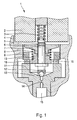
- FIG. 1 The representation according to FIG. 1 is to be taken from a known from the prior art solenoid valve whose armature plate is acted upon by an overstroke spring, which in turn is supported on a stationary, arranged in the injector anchor bolt guide.
- solenoid valve 1 comprises a magnet 2, which is accommodated in the valve housing 4.
- the magnet 2 encloses a closing spring 3, which acts on an upper end face of an anchor bolt 6.
- a mechanical stop 5 is provided, which may be formed for example as a sickle disc and the upper stroke limit for the armature pin 6 movably received anchor plate 7 represents.
- the anchor plate 7 in turn is acted upon by an overstroke spring 8, which is supported on an anchor bolt guide 10.
- the anchor bolt guide 10 is fastened in the valve housing 4 via a valve clamping screw 9.
- one or more holes 16 may be formed, which allow the overflow of fuel in the leakage region of the fuel injector.
- the anchor bolt guide 10 is employed on a valve member 11.
- the anchor bolt 6 with an armature plate 7, which is held movably thereon, comprises a spherical cap 12, in which, in the illustration according to FIG FIG. 1 Spherically shaped closing element 13 is inserted, which may be, for example, a ceramic ball.
- the ceramic ball is placed by the anchor bolt 6 in a valve seat and thus closes an outlet throttle 14, via which a control chamber 15 of an in FIG. 1 Not shown fuel injector is pressure relieved.
- FIG. 1 known from the prior art design of a solenoid valve, in particular at short injection intervals of ⁇ 800 microseconds between pilot injection and main injection, a significant increases in the absolute quantities and to observe a large increase in the scatters between two main injections when the anchor plate 7 impacts on the stop 5 made as a sickle disk.
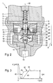
- FIG. 2 is a first embodiment of an inventively proposed Magnetankerein extract refer to a solenoid valve for actuating a fuel injector.
- the FIG. 2 removable solenoid valve 1 comprises the magnetic coil 2, which is arranged opposite the top of the anchor plate 7.
- the armature plate 7 is movably received on the anchor bolt 6 via a stop 5 designed as a sickle disk, whose axis of symmetry is identified by reference numeral 22.
- the anchor bolt 6 is acted upon by the closing spring 3.
- the valve housing 4 serves to receive a valve clamping screw 9 provided with an external thread, via which the bolt guide 10 is fastened in the valve housing 4.
- the bolt guide 10 rests on an upper plane surface of the valve piece 11, in which the discharge throttle space 34 is formed, which has on its side facing the discharge throttle 14 a funnel 33 in which a valve seat 32 is formed.
- the valve seat 32 is shown in the illustration FIG. 2 closed by a spherical closure member 13 which may be formed, for example, as a ceramic ball.
- the closing element 13 is guided in a spherical cap 12 at the lower end of the anchor bolt 6.
- Below the valve seat 32 is located in the valve piece 11, the outlet throttle 14, via which the control chamber 15 is pressure relieved when the closing element 13 is open. In this case flows via the outlet throttle 14 of the valve housing 4, a Abberichtvolumen of fuel from the control chamber 15 in the drain throttle chamber 34 a.
- the anchor bolt 6 has at least one overflow channel 26.
- the at least one overflow channel 26 is acted upon by an inlet opening 27, which is executed in the lower portion of the anchor bolt 6, with fuel.
- the fuel flows with the closing element 13 open via the outlet throttle 14 from the control chamber 15 into the outlet throttle space 34 and from there via the inlet openings 27 into the at least one overflow channel 26.
- the or the overflow channels 26 each have an outflow opening 24.
- the overflow channels 26 can however also be formed in the anchor bolt 6 in such a way that all overflow channels 26 open into a common outflow opening 24.
- the outflow opening 24 is in relation to the anchor bolt 6 so that it opens in the region between the end face 23 of the stationary anchor bolt guide 10 and below the anchor plate holder 20. This flows out of the overflow 26 exiting Fuel at a point in the Abêtraum 35, in which advantageously a hydraulic pressure pad can be constructed.
- the armature plate neck 20 has a chamfer 21 on its end facing the end face 23 of the stationary anchor bolt guide 10.
- the chamfer 21 extends in a cone angle from outside to inside towards the lateral surface of the anchor bolt 6.
- the chamfer 21 is delimited by a chamfer edge 25, so that a space formed in accordance with the angle of inclination of the conical surface forms, which can be filled with the fuel volume leaving the outflow openings 24 of the overflow channels 26. Due to the formation of the chamfer 21, premature discharge of fuel from the damping pad is avoided.
- the number of overflow channels 26 on the anchor bolt 6 can be arbitrary, but is limited by the fact that the overflow 26 should not represent hydraulic throttles and therefore should be sufficiently large in terms of their diameter.
- the number of overflow channels 26 that can be formed on the anchor bolt 6 depends on the diameter of the anchor bolt 6 and on the production possibilities.
- Each of the transfer ports 26 has its own discharge port 24 so as not only to utilize the static cushion formed in the hydraulic space surrounding the anchor bolt 6, but also to utilize an additional dynamic upstream force.
- a symmetrical arrangement of the overflow 26 at the periphery of the anchor bolt 6 is advantageous to minimize lateral forces in the guides between anchor bolt 6 and armature guide 10 and anchor bolt 6 and anchor plate 7.
- the hydraulic cushion above the end face 23 of the stationary anchor bolt guide 10 and below the chamfer 21 on the neck portion 20 of the anchor plate 7 is not permanently on, but is effective only in the open state of the closing element 13 and immediately after closing the closing element 13, that is, after this has reached the valve seat 32.
- a bouncing of the upper plane of the anchor plate 7 can be significantly attenuated to the underside of the serving as a stopper sickdle 5.
- Reference number 30 shows the return flow quantities flowing from the outlet throttle control space 34 into the further hydraulic space 35, while reference number 31 designates the fuel volume leaving the discharge opening or openings 24, which serves to dampen the movement of the armature plate 7.
- the anchor plate 7 can be quickly returned by the emerging from the or the discharge ports 24 fuel back to its original position, wherein the striking of the upper plane of the anchor plate 7 on the executed as a sickle disc stop. 5 with a relatively small pulse.
- the flow of the Abêtmenge within the discharge throttle chamber 34 is present shortly after the closing of the valve seat 32 by the closing element 13.
- the relatively small leakage quantities of nozzles and valve guide are permanently available.
- the anchor plate 7 Due to the fuel flowing through the flow process of the Abgresmenge in the discharge throttle space 34 in the transfer ports 26 and the leakage of fuel through the discharge port 24 between the end face 23 and bevel 21 can quickly return the armature plate 7 in its initial position. Due to the small self-adjusting leakage amount, indicated by the arrow 31, the anchor plate 7 can impinge on the designed as a sickle disk stop 5 and held there with only a small pulse. With reference numeral 31, the second return amount is referred to, which flows from the annular channel above the anchor bolt guide 10.
- the return movement of the armature plate 7 to the stop 5 takes place with progressive stroke and decreasing axial force in the direction of the starting position, so that a wear-causing impact of anchor plate 7 and stopper 5, which can be formed as a sickle disc, can be achieved.
- the amount of fuel exiting from the outflow openings 24 is so dimensioned that the armature plate 7 is returned to its initial position, ie in contact with the stop 5, until the next injection process.
- different opening behavior leads to increased stroke / stroke spread of the injection quantities, which is highly undesirable.
- the representation according to FIG. 3 are the Hubverrise an anchor plate removed, which is damped with a spring or as proposed by the invention with a hydraulic stop.
- the curve identified by reference numeral 40 denotes the slope of a curve which describes the return speed of the armature plate 7 to its starting position.
- the curve increases with the first slope 40 to a turning point 45, at which the curve assumes a second slope 42, which is caused due to leakage flows 31.
- Reference numeral 43 designates a speed which has an armature plate 7 when it is reset by an overstroke spring (compare overstroke spring 8 in the illustration according to FIG. 1 ). Due to the spring force that builds up only slowly, the return movement of an armature plate 7 acted upon by the overstroke spring 8 takes place substantially more slowly.
- a self-adjusting overswing is characterized, as seen over the time axis, asymptotically decaying.
- the anchor plate must pass through 7, after a closing operation of the anchor bolt 6, that is placed in the valve seat 32 closing element 13, to reach their original position again, characterized by an investment in the form of a sickle disk stop 5 is.
Landscapes
- Engineering & Computer Science (AREA)
- Chemical & Material Sciences (AREA)
- Combustion & Propulsion (AREA)
- Mechanical Engineering (AREA)
- General Engineering & Computer Science (AREA)
- Physics & Mathematics (AREA)
- Fluid Mechanics (AREA)
- Fuel-Injection Apparatus (AREA)
Description
- Magnetventile können an Kraftstoffeinspritzanlagen zur Betätigung von Kraftstoffinjektoren eingesetzt werden. Dazu umfassen die Magnetventile einen in den Injektorkörper eingelassenen Elektromagneten, welcher mit einer Ankergruppe zusammenarbeitet, die einen Ankerbolzen und eine Ankerplatte umfasst. Der Ankerbolzen ist so ausgestaltet, dass an diesem ein Schließkörper aufgenommen ist, der einen Ablauf eines die Düsennadel des Kraftstoffinjektors betätigenden Steuerraumes verschließt oder freigibt. Zur Erzielung einer genauen Hubbewegung der Ankergruppe bei Erregung des Elektromagneten ist eine betriebssichere und spielfreie Verbindung von Ankerplatte und Ankerbolzen bei zweiteiligen Ankerbaugruppen beziehungsweise bei Ankerführungshülse und Ankerbolzen bei einteiligen Ankern erforderlich.
-
DE 196 50 865 A1 bezieht sich auf ein Magnetventil. Dessen Anker ist mehrteilig ausgebildet. Der Anker umfasst eine Ankerscheibe und einen Ankerbolzen, der in einem Gleitstück geführt wird. Um ein Nachschwingen der Ankerscheibe nach einem Schließen des Magnetventils zu vermeiden, ist am Magnetanker eine Dämpfungseinrichtung ausgeführt. Mit einer solchen Einrichtung sind exakt die erforderlichen kurzen Schaltzeiten des Magnetventils einhaltbar und auch reproduzierbar. Dieses Magnetventil ist bestimmt zur Anwendung bei Einspritzanlagen, insbesondere Hochdruckeinspritzanlagen wie zum Beispiel solche mit Hochdrucksammelraum (Common Rail). - Eine Dämpfungseinrichtung, mit der ein Nachschwingen des ersten Ankerteiles bei seiner dynamischen Verschiebung dämpfbar ist, umfasst einen ersten Ankerteil, der einen in axiale Richtung weisenden Ansatz enthält, der in eine zum Ansatz komplementär ausgebildete, ortsfest angeordnete Aussparung eines Gleitstücks bei einer Verschiebung des ersten Ankerteils eintauchen kann. Dabei schließt die Aussparung mit dem Ansatz einen Dämpfungsraum ein, der über eine Leckspalt Verbindung mit einem ihm umgebenden Entlastungsraum hat.
- Alternativ kann am Ankerbolzen eine Ringschulter angeordnet werden, die von einem Teil des ersten Ankerteils umschlossen ist und an dem ersten Ankerteil ebenfalls eine Ringschulter angebracht ist, zwischen der und der Ringschulter des Ankerbolzens ständig ein Dämpfungsraum eingeschlossen ist, der seinerseits über einen Leckspalt eine Verbindung zu einem ihm umgebenden Entlastungsraum aufweist.
- Gemäß dieser Lösung mit einem durch einen Elektromagneten betätigbaren, zweiteilig ausgebildeten Anker, ist zwischen dem Ankerbolzen und der Ankerplatte ein Anschlagring eingelassen. Der Anschlagring ist als offene Sicherungsscheibe ausgebildet und neigt zum Ausschlagen. Es können stärkere Verschleißerscheinungen auftreten, die zu einem zu sich einstellendem Spiel zwischen Ankerbolzen und Ankerplatte und zum anderen zur vollständigen Zerstörung der Sicherungsscheibe führen können. Ein sich einstellendes Spiel zwischen Ankerbolzen und Ankerplatte beeinflusst die Mengentoleranzen bei der Einspritzung nachteilig, so dass insbesondere eine Reproduzierbarkeit bei in kurzen Abständen aufeinander folgenden Einspritzungen kleinster Mengen nicht mehr gegeben ist.
- Aus
DE 101 33 450 A1 ist ein Magnetventil mit einer Steck-Drehverbindung bekannt. Das Magnetventil kommt an einem Kraftstoffinjektor zum Einspritzen von Kraftstoff in den Brennraum einer Verbrennungskraftmaschine zum Einsatz, wobei der Kraftstoffinjektor einen Injektorkörper sowie einen Elektromagneten umfasst. Mit diesem ist eine Ankerbaugruppe des Magnetventils zur Druckentlastung eines Steuerraums betätigbar, so dass eine im Injektorkörper vorhandene Düsennadelanordnung eine Öffnungs- beziehungsweise einer Schließbewegung ausführt. Die Ankergruppe enthält ein erstes und ein zweites Ankerteil. Das erste Ankerteil und das zweites Ankerteil sind durch eine Steck-Drehverbindung miteinander gefügt, wobei eines der Ankerteile von einer Drehsicherung enthaltenden Ankerführung umgriffen ist. -
EP 0 851 114 A2 offenbart ein Magnetventil mit einer Federbeaufschlagten, gleitend an einem Ankerbolzen aufgenommenen Ankerplatte, wobei ein Quetschspalt unterhalb der Ankerplatte eine hydraulische Dämpfung bewirkt. - Bei heute bekannten Magnetventilen, welche im Zusammenhang mit Kraftstoffinjektoren in Einspritzsystemen zur Kraftstoffversorgung eingesetzt werden, wird der Ankerhub über Einstellringe eingestellt, welche die axiale Lage eines entsprechenden Ankeranschlages festlegen. Über den Anker beziehungsweise über die Bewegung des Ankers in axialer Richtung wird die Öffnung einer Düse des Kraftstoffinjektors und somit die eingespritzte Kraftstoff menge festgelegt. Beim Zusammenbau eines Magnetventiles beziehungsweise eines Kraftstoffinjektors werden die Bauteile, welche den Ankerhub bestimmen, vermessen und anhand der Messergebnisse wird die für ein bestimmten vorgegebenen Ankerhub erforderliche Dimensionierung eines Einstellrings berechnet. Eine Magnetgruppe wird dann zusammen mit dem entsprechend der Berechnung dimensionierten Einstellring im Injektorkörper verschraubt und anschließend wird der Ankerhub mit verschraubtem, beziehungsweise verspanntem Zustand gemessen. Für die Verwendung in Höchstdruckeinspritzsystemen sind für den Ankerhub allenfalls Toleranzen im Mikrometerbereich tolerierbar, um ein reproduzierbares Injektor-Verhalten zu gewährleisten. Aufgrund der erlaubten lediglich geringen Toleranzabweichung befindet sich der Ankerhub nach einer ersten Montage, wie sie oben geschildert wurde, nicht immer innerhalb der Toleranzwerte. Um dann die Einstellung des Ankerhubes innerhalb der engen Toleranzwerte zu gewährleisten, muss die Magnetgruppe vollständig demontiert werden und über die Wahl eines Einstellrings einer anderen Dimensionierung der Ankerhub neu eingestellt werden. Gegebenenfalls muss dieser Vorgang sogar mehrmals wiederholt werden, bis eine akzeptable Toleranzeinhaltung des Ankerhubs erzielt wird.
- Erfindungsgemäß wird vorgeschlagen, zur Minimierung des Mengen- und des Streuungseinflusses bei kurz hintereinander folgenden Einspritzvorgängen das Aufprallen einer Überhubscheibe auf den Ankerbolzen zu verringern, wenn nicht vollständig zu verhindern. Eine bisher zu diesem Zweck eingesetzte Überhubfeder wird durch ein hydraulisches Polster ersetzt.
- Beim Schließen eines Magnetventils bewegen sich die Komponenten Ankerbolzen und Ankerplatte einer zweiteilig ausgebildeten Ankeranordnung gemeinsam in Richtung auf den Ventilsitz. Wenn das Schließelement, was zum Beispiel als eine Keramikkugel ausgebildet sein kann, im Ventilsitz aufschlägt, trennen sich Ankerplatte und Ankerbolzen. Die Ankerplatte vermag in einen Überhubbereich durchzuschwingen. Durch die Trennung von Ankerbolzen und Ankerplatte beim Schließvorgang, wird die Impulskraft und damit das "Schließprellen" verringert. Die bisher eingesetzte Überhubfeder drückt die Ankerplatte vor der nächstfolgenden Einspritzung wieder in ihre Ausgangsposition zurück. Wenn nun Einspritzvorgänge in kurzen Zeitabständen stattfinden, bevor eine bisher eingesetzte Überhubfeder die Ankerplatte in ihre Ausgangsposition zurückgestellt hat, verschlechtert sich die Qualität von Einspritzmenge und Einspritzstreuung. Durch die erfindungsgemäß vorgeschlagenen, im Inneren des Ankerbolzens ausgebildeten Überströmkanäle, besteht nunmehr eine hydraulische Verbindung, um eine über eine Ablaufdrossel abgesteuerte Kraftstoffmenge vom Ablaufdrosselraum in einen hydraulischen Raum einzuleiten. Das die Überströmkanäle durchströmende Fluid, das heißt, der Kraftstoff, mündet in den weiteren hydraulischen Raum oberhalb einer stationär montierten Ankerbolzenführung. Dazu münden die Austrittsöffnung beziehungsweise die Austrittsöffnungen bei mehreren Überströmkanälen, im Bereich zwischen der Oberseite der stationär montierten Ankerbolzenführung und unterhalb eines Halsbereiches der am Ankerbolzen bewegbar aufgenommenen Ankerplatte. Der aus der Austrittsöffnung des einen oder der mehreren Überströmkanäle austretende Kraftstoff baut zwischen einer oberen Stirnfläche der stationär montierten Ankerbolzenführung und der Unterseite eines Halsbereiches der Ankerplatte ein hydraulisches Polster auf, welches die am Ankerbolzen bewegbar geführte Ankerplatte dämpft.
- Am Halsbereich der Ankerplatte auf der der Stirnfläche der stationären Ankerbolzenführung zuweisenden Seite des Halsbereiches wird bevorzugt eine Fase ausgebildet. Die Fase verläuft in radialer Richtung gesehen von außen nach innen und wird von einem Fasenrand begrenzt. Durch eine derart ausgebildete Fase an der Unterseite des Halsabschnittes der Ankerplatte wird das Abströmen von Kraftstoff, welcher über die Austrittsöffnung oder die Austrittsöffnungen an der Mantelfläche des Ankerbolzens zwischen der stationären Ankerbolzenführung und der Unterseite des Halsbereiches in den weiteren hydraulischen Raum eintritt, aus der durch eine Kegelfläche und ein Fasenrand begrenzten Anordnung vermieden. Dadurch verbleibt stets ein Fluid-Vorrat in dem durch die konische Fläche der Fase und dem Fasenrand sowie der Mantelfläche des Ankerbolzens begrenzten Raum, der dann auf die Ankerplatte einwirkt.
- Durch die erfindungsgemäß vorgeschlagene Lösung wird auf die am Ankerbolzen geführte Ankerplatte eine Rückstellkraft ausgeübt, die jedoch nicht immer permanent auf die Ankerplatte einwirkt. Nur im geöffneten Zustand des kugelförmig ausgebildeten Schließelementes und gleich nach dem Schließen des Schließelementes, das heißt dessen Anliegen am Ventilsitz, ist eine Rückstellkraft vorhanden, welche das Aufprallen der Ankerplatte auf einen als Sichelscheibe ausgebildeten Anschlag somit verringert beziehungsweise dämpft.
- Anhand der Zeichnung wird die Erfindung nachstehend eingehender beschrieben.
- Es zeigt:
- Figur 1
- ein aus dem Stand der Technik bekanntes Magnetventil zur Ansteuerung eines Kraftstoffinjektors, mit einer Überhubfeder, die zwischen der Ankerplatte und einer Ankerbolzenführung stationär aufgenommen ist,
- Figur 2
- eine erste Ausführungsvariante der erfindungsgemäß vorgeschlagenen Lösung mit im Ankerbolzen ausgebildeten Überströmkanälen zur hydraulischen Verwendung eines Ablaufsteuerraumes mit einem weiteren hydraulischen Raum, und
- Figur 3
- über die Zeitachse aufgetragene Bewegungszeiten einer Ankerplatte, die über eine Überhubfeder beaufschlagt ist sowie mit einem hydraulischen Polster gedämpft wird.
- Der Darstellung gemäß
Figur 1 ist ein aus dem Stand der Technik bekanntes Magnetventil zu entnehmen, dessen Ankerplatte durch eine Überhubfeder beaufschlagt ist, die sich ihrerseits auf einer stationär, im Injektorkörper angeordneten Ankerbolzenführung abstützt. - Das in
Figur 1 dargestellte Magnetventil 1 umfasst einen Magneten 2, der im Ventilgehäuse 4 aufgenommen ist. Der Magnet 2 umschließt eine Schließfeder 3, die eine obere Stirnseite eines Ankerbolzens 6 beaufschlagt. Oberhalb einer Ankerplatte 7 ist ein mechanischer Anschlag 5 vorgesehen, der beispielsweise als Sichelscheibe ausgebildet sein kann und die obere Hubbegrenzung für die am Ankerbolzen 6 bewegbar aufgenommene Ankerplatte 7 darstellt. Die Ankerplatte 7 ihrerseits ist über eine Überhubfeder 8 beaufschlagt, die sich an einer Ankerbolzenführung 10 abstützt. Der Ankerbolzenführung 10 ist in dem Ventilgehäuse 4 über eine Ventilspannschraube 9 befestigt. In der Ankerbolzenführung 10 können ein oder mehrere Bohrungen 16 ausgebildet sein, die das Überströmen von Kraftstoff in den Leckagebereich des Kraftstoffinjektors ermöglichen. Über die Ventilspannschraube 9 ist die Ankerbolzenführung 10 an ein Ventilstück 11 angestellt. - Der Ankerbolzen 6 mit daran bewegbar aufgenommener Ankerplatte 7 umfasst eine Kugelkalotte 12, in welcher ein in der Darstellung gemäß
Figur 1 kugelförmig ausgebildetes Schließelement 13 eingelassen ist, bei dem es sich zum Beispiel um eine Keramikkugel handeln kann. Die Keramikkugel wird durch den Ankerbolzen 6 in einen Ventilsitz gestellt und verschließt damit eine Ablaufdrossel 14, über welche ein Steuerraum 15 eines inFigur 1 nicht näher dargestellten Kraftstoffinjektors druckentlastbar ist. - Mit der in
Figur 1 dargestellten, aus dem Stand der Technik bekannten Auslegung eines Magnetventils, sind insbesondere bei kurzen Einspritzabständen von < 800 µs zwischen Voreinspritzung und Haupteinspritzung eine erhebliche Zunahmen der Absolutmengen und eine starke Zunahme der Streuungen zwischen zwei Haupteinspritzungen beim Aufprallen der Ankerplatte 7 auf den als Sichelscheibe ausgeführten Anschlag 5 zu beobachten. - Der Darstellung gemäß
Figur 2 ist eine erste Ausführungsvariante einer erfindungsgemäß vorgeschlagenen Magnetankereinordnung für ein Magnetventil zur Betätigung eines Kraftstoffinjektors zu entnehmen. DasFigur 2 entnehmbare Magnetventil 1 umfasst die Magnetspule 2, die der Oberseite der Ankerplatte 7 gegenüberliegend angeordnet ist. Die Ankerplatte 7 ist über einen als Sichelscheibe ausgebildeten Anschlag 5 am Ankerbolzen 6 bewegbar aufgenommen, dessen Symmetrieachse durch Bezugszeichen 22 identifiziert ist. Der Ankerbolzen 6 wird über die Schließfeder 3 beaufschlagt. Das Ventilgehäuse 4 dient zur Aufnahme einer mit einem Außengewinde versehenen Ventilspannschraube 9, über welche die Bolzenführung 10 im Ventilgehäuse 4 befestigt wird. - Die Bolzenführung 10 liegt auf einer oberen Planfläche des Ventilstückes 11 auf, in welchem der Ablaufdrosselraum 34 ausgebildet ist, der auf seiner der Ablaufdrossel 14 zuweisenden Seite einen Trichter 33 aufweist, in dem ein Ventilsitz 32 ausgebildet ist. Der Ventilsitz 32 ist in der Darstellung gemäß
Figur 2 durch ein kugelförmig ausgebildetes Schließelement 13 verschlossen, welches zum Beispiel als eine Keramikkugel ausgebildet sein kann. Das Schließelement 13 ist in einer Kugelkalotte 12 am unteren Ende des Ankerbolzens 6 geführt. Unterhalb des Ventilsitzes 32 befindet sich im Ventilstück 11 die Ablaufdrossel 14, über welche bei geöffnetem Schließelement 13 der Steuerraum 15 druckentlastbar ist. In diesem Fall strömt über die Ablaufdrossel 14 des Ventilgehäuses 4 ein Absteuervolumen von Kraftstoff aus dem Steuerraum 15 in den Ablaufdrosselraum 34 ein. - Der Ankerbolzen 6 weist mindestens eine Überströmkanal 26 auf. Der mindestens eine Überströmkanal 26 wird über eine Einströmöffnung 27, die im unteren Abschnitt des Ankerbolzens 6 ausgeführt ist, mit Kraftstoff beaufschlagt. Der Kraftstoff strömt bei geöffnetem Schließelement 13 über die Ablaufdrossel 14 aus dem Steuerraum 15 in den Ablaufdrosselraum 34 ein und von dort über die Einströmöffnungen 27 in den mindestens einen Überströmkanal 26. Der oder die Überströmkanäle 26 weisen jeweils eine Ausströmöffnung 24 auf. Die Überströmkanäle 26 können jedoch im Ankerbolzen 6 jedoch auch so ausgebildet werden, dass sämtliche Überströmkanäle 26 in eine gemeinsame Ausströmöffnung 24 münden.
- Die Ausströmöffnung 24 liegt in Bezug auf den Ankerbolzen 6 so, dass diese im Bereich zwischen der Stirnfläche 23 der stationären Ankerbolzenführung 10 und unterhalb des Ankerplattenhalters 20 mündet. Damit strömt der aus den Überströmkanälen 26 austretende Kraftstoff an einer Stelle in den Absteuerraum 35 ein, in welchem in vorteilhafter Weise eine hydraulisches Druckpolster aufgebaut werden kann.
- Zur Verbesserung der Dämpfungseigenschaften weist der Ankerplattenhals 20 an seinen der Stirnfläche 23 der stationären Ankerbolzenführung 10 zuweisenden Ende eine Fase 21 auf. Die Fase 21 verläuft in einem Kegelwinkel von außen nach innen hin auf die Mantelfläche des Ankerbolzens 6 zu. Die Fase 21 wird von einem Fasenrand 25 begrenzt, so dass sich ein entsprechend des Neigungswinkels der Kegelfläche ausgebildeter Raum bildet, welcher mit dem aus den Ausströmöffnungen 24 der Überströmkanäle 26 austretenden Kraftstoffvolumen befüllbar ist. Aufgrund der Ausbildung der Fase 21 wird ein vorzeitiges Abströmen von Kraftstoff aus dem Dämpfungspolster vermieden. Die Anzahl der Überströmkanäle 26 am Ankerbolzen 6 kann beliebig sein, ist jedoch dadurch begrenzt, dass die Überströmkanäle 26 keine hydraulischen Drosseln darstellen sollen und deswegen hinsichtlich ihres Durchmessers ausreichend groß dimensioniert sein sollen. Die Anzahl der am Ankerbolzen 6 ausbildbaren Überströmkanäle 26 hängt vom Durchmesser des Ankerbolzens 6 und von den Fertigungsmöglichkeiten ab. Jeder der Überströmkanäle 26 hat eine eigene Ausströmöffnung 24, um nicht nur das im hydraulischen Raum, welcher den Ankerbolzen 6 umgibt, ausgebildete statische Polster zu nutzen, sondern auch eine zusätzliche dynamische Anströmkraft zu nutzen. Eine symmetrische Anordnung der Überströmkanäle 26 am Umfang des Ankerbolzens 6 ist von Vorteil, um Querkräfte in den Führungen zwischen Ankerbolzen 6 und Ankerführung 10 sowie Ankerbolzen 6 und Ankerplatte 7 zu minimieren.
- Das hydraulische Polster oberhalb der Stirnfläche 23 der stationären Ankerbolzenführung 10 und unterhalb der Fase 21 am Halsabschnitt 20 der Ankerplatte 7 liegt nicht permanent an, sondern wird nur in geöffnetem Zustand des Schließelementes 13 wirksam und unmittelbar nach dem Schließen des Schließelementes 13, das heißt, nachdem dieses den Ventilsitz 32 erreicht hat. Mit der erfindungsgemäß vorgeschlagenen Lösung kann ein Aufprallen der oberen Planfläche der Ankerplatte 7 an die Unterseite der als Anschlag dienenden Sichelscheibe 5 erheblich gedämpft werden. Mit Bezugszeichen 30 sind die vom Ablaufdrosselsteuerraum 34 in den weiteren hydraulischen Raum 35 einströmenden Rücklaufmengen dargestellt, während Bezugszeichen 31 das aus der oder den Ausströmöffnungen 24 austretenden Kraftstoffvolumen bezeichnet, welches zur Dämpfung der Bewegung der Ankerplatte 7 dient.
- Insbesondere bei kurzen Zeitabständen zwischen aufeinander folgenden Einspritzvorgängen kann die Ankerplatte 7 durch den aus der oder den Ausströmöffnungen 24 austretenden Kraftstoff schnell wieder in ihre Ausgangslage zurückgestellt werden, wobei das Anschlagen der oberen Planfläche der Ankerplatte 7 an dem als Sichelscheibe ausgeführten Anschlag 5 mit einem relativ geringen Impuls erfolgt. In vorteilhafter Weise wird ausgenützt, dass die Strömung der Absteuermenge innerhalb des Ablaufdrosselraumes 34 kurz bis nach dem Schließen des Ventilsitzes 32 durch das Schließelement 13 vorhanden ist. Demgegenüber stehen die relativ geringen Leckmengen von Düsen und Ventilführung permanent zur Verfügung.
- Aufgrund des durch den Strömungsvorgang der Absteuermenge im Ablaufdrosselraum 34 in die Überströmkanäle 26 einströmenden Kraftstoffes und des Austretens des Kraftstoffes über die Ausströmöffnung 24 zwischen Stirnfläche 23 und Fase 21 kann ein schnelles Rückstellen der Ankerplatte 7 in ihre Ausgangsposition folgen. Durch die geringe sich einstellende Leckmenge, angedeutet durch den Pfeil 31, kann die Ankerplatte 7 mit nur einem geringen Impuls auf den als Sichelscheibe ausgebildeten Anschlag 5 auftreffen und dort gehalten werden. Mit Bezugszeichen 31 ist die zweite Rücklaufmenge bezeichnet, welche aus dem Ringkanal oberhalb der Ankerbolzenführung 10 strömt. Die Rückstellbewegung der Ankerplatte 7 an den Anschlag 5 erfolgt bei fortschreitenden Hub und abnehmender axialer Kraft in Richtung der Ausgangslage, so dass ein Verschleiß verursachendes Auftreffen von Ankerplatte 7 und Anschlag 5, der als Sichelscheibe ausgebildet werden kann, erreicht werden kann. Die Menge von aus den Ausströmöffnungen 24 austretendem Kraftstoff ist so bemessen, dass die Ankerplatte 7 bis zum nächsten Einspritzvorgang wieder in ihrer Ausgangslage, d.h. in Kontakt mit dem Anschlag 5 zurückgestellt ist. Erfolgt der nächste Einspritzvorgang jedoch früher, kommt es durch unterschiedliche Öffnungsverhalten zu erhöhter Hub/Hubstreuung der Einspritzmengen, was höchst unerwünscht ist. Beim Ventilschließen, welches durch den Pfeil A in
Figur 2 angedeutet ist, dämpft die dynamische Strömung des aus den Ausströmöffnungen 24 austretenden Kraftstoffes und die statische Menge von Kraftstoff, die im Ringkanal oberhalb der Ankerbolzenführung 10 enthalten ist, das Durchschwingen der Ankerplatte 7. Ein Kontakt der Ankerplatte mit der Stirnfläche 23 der Ankerbolzenführung 10 ist nicht erforderlich, jedoch möglich. - Der Darstellung gemäß
Figur 3 sind die Hubverläufe einer Ankerplatte entnehmbar, die mit einer Feder beziehungsweise wie erfindungsgemäß vorgeschlagen mit einem hydraulischen Anschlag gedämpft ist. - Der durch Bezugszeichen 40 identifizierte Kurvenzug bezeichnet die Steigung einer Kurve, welche die Rückstellgeschwindigkeit der Ankerplatte 7 in ihre Ausgangsposition beschreibt. Der Kurvenzug steigt mit der ersten Steigung 40 bis zu einem Wendepunkt 45, zu dem der Kurvenzug eine zweite Steigung 42 annimmt, die aufgrund von Leckageströmen 31 verursacht wird.
- Durch Bezugszeichen 43 ist eine Geschwindigkeit gekennzeichnet, die eine Ankerplatte 7 aufweist, wenn ihr Rückstellen durch eine Überhubfeder erfolgt (vgl. Überhubfeder 8 in der Darstellung gemäß
Figur 1 ). Aufgrund der sich nur langsam aufbauenden Federkraft erfolgt die Rückstellbewegung einer über die Überhubfeder 8 beaufschlagten Ankerplatte 7 wesentlich langsamer. Mit Bezugszeichen 44 ist ein sich einstellender Überschwung gekennzeichnet, der über die Zeitachse gesehen, asymptotisch abklingt. Durch ÜH ist der gesamte Überhubbereich gekennzeichnet, den die Ankerplatte 7 durchfahren muss, um nach einem Schließvorgang des Ankerbolzens 6, das heißt in den Ventilsitz 32 gestellten Schließelement 13, wieder ihre Ausgangsposition zu erreichen, die durch eine Anlage am als Sichelscheibe ausgebildeten Anschlag 5 charakterisiert ist. - Bei der Rückstellung der Ankerplatte 7 durch eine Federkraft gemäß des Kurvenzuges 43 wirkt über den gesamten Überhubbereich ÜH die gleiche Kraft auf die Ankerplatte 7. Bei der erfindungsgemäß vorgeschlagenen hydraulischen Rückstellung wirkt aufgrund der am Anfang sich einstellenden Überströmmenge und des engen Leckspaltes zwischen der Ankerplatte 7 und der Ankerbolzenführung 10 eine große Rückstellkraft. Nach dem Ventilschließen in Richtung des Pfeiles A und nach dem sich die Ankerplatte 7 und die Ankerbolzenführung 10 weiter voneinander entfernt haben, hält nur noch eine geringe Kraft die Ankerplatte 7 in ihrer Ausgangsposition. In ihrer Ausgangsposition liegt die Ankerplatte 7 an dem als Sichelscheibe ausgebildeten Anschlag 5 an.
-
- 1
- Magnetventil
- 2
- Magnet
- 3
- Schließfeder
- 4
- Ventilgehäuse
- 5
- Anschlag (Sichelscheibe)
- 6
- Ankerbolzen
- 7
- Ankerplatte
- 8
- Überhubfeder
- 9
- Ventilspannschraube
- 10
- Ankerbolzenführung
- 11
- Ventilstück
- 12
- Kugelkalotte
- 13
- Schließelement (Keramikkugel)
- 14
- Ablaufdrossel
- 15
- Steuerraum
- 16
- Überströmbohrung
- 20
- Ankerplattenhals
- 21
- Fase
- 22
- Symmetrieachse
- 23
- Stirnfläche Ankerbolzenführung
- 24
- Ausströmöffnung
- 25
- Fasenrand
- 26
- Überströmkanal
- 27
- Einströmöffnung
- 28
- Überströmkanal-Neigungswinkel
- 29
- Einströmbereich
- 30
- erste Rücklaufmenge
- 31
- zweite Rücklaufmenge
- 32
- Ventilsitz
- 33
- Trichter
- 34
- Ablaufdrosselraum
- 35
- Absteuerraum
- 40
- erste Steigung anhand Steuermenge
- 42
- zweite Steigung aufgrund Leckölmenge
- 43
- Steigung aufgrund Federkraft
- 44
- Überschwinger
- 45
- Wendepunkt
- ÜH
- Überhub
Claims (10)
- Magnetventil zur Betätigung eines Kraftstoffinjektors mit einem Schließelement (13), über das eine Ablaufdrossel (14) eines Steuerraumes (15) freigebbar oder verschließbar ist, einem Ankerbolzen (6) mit einer an diesem beweglich aufgenommenen Ankerplatte (7), die am Ankerbolzen (6) gesichert ist und einem der Ankerplatte (7) gegenüberliegend angeordneten Magneten (2), dadurch gekennzeichnet, dass im Ankerbolzen (6) mindestens ein Überströmkanal (26) ausgebildet ist, über den ein Ablaufdrosselraum (34) und ein Absteuerraum (35) hydraulisch zum Aufbau eines hydraulischen Polsters unterhalb der Ankerplatte (7) miteinander verbunden sind.
- Magnetventil gemäß Anspruch 1, dadurch gekennzeichnet, dass mindestens eine Austrittsöffnung (24) mindestens eines Überströmkanals (26) zwischen einer Stirnfläche (23) und einer Ankerbolzenführung (10) und unterhalb eines Ankerplattenhalses (20) in den Absteuerraum (35) mündet.
- Magnetventil gemäß Anspruch 2, dadurch gekennzeichnet, dass der Ankerplattenhals (20) eine Fase (21) aufweist.
- Magnetventil gemäß Anspruch 3, dadurch gekennzeichnet, dass ein Kegelwinkel der Fase (21) radial von außen nach innen verläuft.
- Magnetventil gemäß Anspruch 3, dadurch gekennzeichnet, dass die Fase (21) nach außen durch einen Fasenrand (25) begrenzt ist.
- Magnetventil gemäß Anspruch 1, dadurch gekennzeichnet, dass mindestens eine Einströmöffnung (27) mindestens eines Überströmkanales (26) von im Ablaufdrosselraum (34) enthaltenem Kraftstoff beaufschlagt ist.
- Magnetventil gemäß Anspruch 1, dadurch gekennzeichnet, dass Überströmkanäle (26) im Ankerbolzen (6) um einen Neigungswinkel (28) bezogen auf die Symmetrieachse (22) des Ankerbolzens (6) geneigt verlaufen.
- Magnetventil gemäß Anspruch 1, dadurch gekennzeichnet, dass das Schließelement (13) als Keramikkugel ausgebildet ist und in einer Kugelkalotte (12) des Ankerbolzens (6) geführt ist.
- Magnetventil gemäß Anspruch 1, dadurch gekennzeichnet, dass dieses mit einem zweiteiligen Anker, eine Ankerplatte (7) und einen Ankerbolzen (6) umfassend ausgebildet ist und die Ankerplatte (7) relativ beweglich zum Ankerbolzen (6) angeordnet ist, wobei die Ankerplatte (7) überhubfederfrei hydraulisch gegen einen Anschlag (5) zurückstellbar ist.
- Verwendung eines Magnetventiles gemäß einem oder mehrerer der vorhergehenden Ansprüche in einem Kraftstoffinjektor an einem Common-Rail-Hochdruckeinspritzsystem.
Applications Claiming Priority (2)
| Application Number | Priority Date | Filing Date | Title |
|---|---|---|---|
| DE102004050992A DE102004050992A1 (de) | 2004-10-20 | 2004-10-20 | Magnetventilbetätigter Kraftstoffinjektor mit hydraulischem Überhubanschlag |
| PCT/EP2005/055108 WO2006042798A1 (de) | 2004-10-20 | 2005-10-07 | Magnetventilbetätigter kraftstoffinjektor mit hydraulischem überhubanschlag |
Publications (2)
| Publication Number | Publication Date |
|---|---|
| EP1805409A1 EP1805409A1 (de) | 2007-07-11 |
| EP1805409B1 true EP1805409B1 (de) | 2008-02-27 |
Family
ID=35502958
Family Applications (1)
| Application Number | Title | Priority Date | Filing Date |
|---|---|---|---|
| EP05801500A Expired - Lifetime EP1805409B1 (de) | 2004-10-20 | 2005-10-07 | Magnetventilbetätigter kraftstoffinjektor mit hydraulischem überhubanschlag |
Country Status (5)
| Country | Link |
|---|---|
| EP (1) | EP1805409B1 (de) |
| JP (1) | JP4495761B2 (de) |
| AT (1) | ATE387577T1 (de) |
| DE (2) | DE102004050992A1 (de) |
| WO (1) | WO2006042798A1 (de) |
Families Citing this family (9)
| Publication number | Priority date | Publication date | Assignee | Title |
|---|---|---|---|---|
| US7303014B2 (en) | 2004-10-26 | 2007-12-04 | Halliburton Energy Services, Inc. | Casing strings and methods of using such strings in subterranean cementing operations |
| US7303008B2 (en) | 2004-10-26 | 2007-12-04 | Halliburton Energy Services, Inc. | Methods and systems for reverse-circulation cementing in subterranean formations |
| DE102006045357A1 (de) * | 2006-09-26 | 2008-04-03 | Robert Bosch Gmbh | Sicherungsscheibe für ein Magnetventil |
| DE102007037824A1 (de) * | 2007-08-10 | 2009-02-12 | Robert Bosch Gmbh | Kraftstoffeinspritzventil für Brennkraftmaschinen |
| DE102008002717A1 (de) * | 2008-06-27 | 2010-01-14 | Robert Bosch Gmbh | Kraftstoffinjektor mit zweiteiligem Magnetanker |
| EP2138706B1 (de) | 2008-06-27 | 2010-11-10 | C.R.F. Società Consortile per Azioni | Kraftstoffeinspritzgerät mit symmetrischem Mess-Servoventil für einen Verbrennungsmotor |
| DE602008005349D1 (de) * | 2008-12-29 | 2011-04-14 | Fiat Ricerche | Brennstoffeinspritzsystem mit hoher Betriebswiederholbarkeit und -stabilität für einen Verbrennungsmotor |
| CN104100424B (zh) * | 2014-07-23 | 2016-06-29 | 哈尔滨工程大学 | 带有电磁阀控制的船用低速机共轨喷油器 |
| CN110397771B (zh) * | 2019-07-20 | 2020-12-01 | 防城港澳加粮油工业有限公司 | 一种使用寿命高的弹簧式安全阀 |
Family Cites Families (6)
| Publication number | Priority date | Publication date | Assignee | Title |
|---|---|---|---|---|
| DE3408012A1 (de) * | 1984-03-05 | 1985-09-05 | Gerhard Dipl.-Ing. Warren Mich. Mesenich | Elektromagnetisches einspritzventil |
| IT1219397B (it) * | 1988-06-23 | 1990-05-11 | Weber Srl | Valvola per la dosatura e la polverizzazione di carburante ad azionamento elettromagnetico provvista di doppia serie di fori laterali di ingresso del carburante |
| DE19650865A1 (de) | 1996-12-07 | 1998-06-10 | Bosch Gmbh Robert | Magnetventil |
| IT239878Y1 (it) * | 1996-12-23 | 2001-03-13 | Elasis Sistema Ricerca Fiat | Perfezionamenti ad una valvola di dosaggio a comando elettromagneticoper un iniettore di combustibile. |
| DE19843546A1 (de) * | 1998-09-23 | 2000-03-30 | Bosch Gmbh Robert | Kraftstoffeinspritzeinrichtung für Brennkraftmaschinen |
| DE10133450A1 (de) | 2001-07-10 | 2003-01-30 | Bosch Gmbh Robert | Magnetventil mit Steck-Drehverbindung |
-
2004
- 2004-10-20 DE DE102004050992A patent/DE102004050992A1/de not_active Withdrawn
-
2005
- 2005-10-07 AT AT05801500T patent/ATE387577T1/de not_active IP Right Cessation
- 2005-10-07 DE DE502005003034T patent/DE502005003034D1/de not_active Expired - Lifetime
- 2005-10-07 WO PCT/EP2005/055108 patent/WO2006042798A1/de not_active Ceased
- 2005-10-07 EP EP05801500A patent/EP1805409B1/de not_active Expired - Lifetime
- 2005-10-07 JP JP2007537253A patent/JP4495761B2/ja not_active Expired - Fee Related
Also Published As
| Publication number | Publication date |
|---|---|
| JP2008517212A (ja) | 2008-05-22 |
| JP4495761B2 (ja) | 2010-07-07 |
| ATE387577T1 (de) | 2008-03-15 |
| WO2006042798A1 (de) | 2006-04-27 |
| EP1805409A1 (de) | 2007-07-11 |
| DE102004050992A1 (de) | 2006-04-27 |
| DE502005003034D1 (de) | 2008-04-10 |
Similar Documents
| Publication | Publication Date | Title |
|---|---|---|
| EP1259729B1 (de) | Magnetventil zur steuerung eines einspritzventils einer brennkraftmaschine | |
| EP3535486B1 (de) | Brennstoffeinspritzventil zum einspritzen eines gasförmigen und/oder flüssigen brennstoffs | |
| EP2116717B1 (de) | Kraftstoff-Injektor | |
| WO2009121646A1 (de) | Magnetventil mit mehrteiligem anker ohne ankerführung | |
| EP2156046A1 (de) | Ankerhubeinstellung für magnetventil | |
| EP2100026B1 (de) | Kraftstoffinjektor mit magnetventil mit kugelsitz | |
| EP2855914B1 (de) | Kraftstoffinjektor | |
| WO2008049666A1 (de) | Injektor mit einem eine konische hubanschlagfläche aufweisenden steuerventil | |
| EP1967726B1 (de) | Magnetventilinjektor | |
| DE102004050992A1 (de) | Magnetventilbetätigter Kraftstoffinjektor mit hydraulischem Überhubanschlag | |
| DE102007044361A1 (de) | Steuerventil für einen Kraftstoffinjektor | |
| EP2123898B1 (de) | Kraftstoff-Injektor | |
| DE102007052753A1 (de) | Kraftstoffinjektor mit optimiertem Absteuerstoß | |
| DE102006053128A1 (de) | Injektor zum Einpritzen von Kraftstoff | |
| EP1541859B1 (de) | Einspritzventil | |
| EP0262197A1 (de) | Einspritzdüse für brennkraftmaschinen. | |
| WO2003004861A1 (de) | Kraftstoffinjektor mit kraftausgeglichenem steuerventil | |
| WO2009121647A1 (de) | Hydraulische dämpfung | |
| WO2001038723A1 (de) | Kraftstoffeinspritzventil für brennkraftmaschinen | |
| DE10154576C1 (de) | Kraftstoffinjektor mit düsennaher Magnetventilanordnung | |
| DE19747092A1 (de) | Durchflußbegrenzungsvorrichtung für Brennkraftmaschinen | |
| EP1404964B1 (de) | Kraftstoffinjektor mit zuschaltbarem steuerraumzulauf | |
| EP2019198A2 (de) | Injektor | |
| EP1339974A1 (de) | Brennstoffeinspritzanlage | |
| DE10164395A1 (de) | Kraftstoffeinspritzvorrichtung für Brennkraftmaschinen |
Legal Events
| Date | Code | Title | Description |
|---|---|---|---|
| PUAI | Public reference made under article 153(3) epc to a published international application that has entered the european phase |
Free format text: ORIGINAL CODE: 0009012 |
|
| 17P | Request for examination filed |
Effective date: 20070521 |
|
| AK | Designated contracting states |
Kind code of ref document: A1 Designated state(s): AT BE BG CH CY CZ DE DK EE ES FI FR GB GR HU IE IS IT LI LT LU LV MC NL PL PT RO SE SI SK TR |
|
| GRAP | Despatch of communication of intention to grant a patent |
Free format text: ORIGINAL CODE: EPIDOSNIGR1 |
|
| GRAS | Grant fee paid |
Free format text: ORIGINAL CODE: EPIDOSNIGR3 |
|
| DAX | Request for extension of the european patent (deleted) | ||
| GRAA | (expected) grant |
Free format text: ORIGINAL CODE: 0009210 |
|
| AK | Designated contracting states |
Kind code of ref document: B1 Designated state(s): AT BE BG CH CY CZ DE DK EE ES FI FR GB GR HU IE IS IT LI LT LU LV MC NL PL PT RO SE SI SK TR |
|
| REG | Reference to a national code |
Ref country code: GB Ref legal event code: FG4D Free format text: NOT ENGLISH |
|
| REG | Reference to a national code |
Ref country code: CH Ref legal event code: EP |
|
| REG | Reference to a national code |
Ref country code: IE Ref legal event code: FG4D Free format text: LANGUAGE OF EP DOCUMENT: GERMAN |
|
| REF | Corresponds to: |
Ref document number: 502005003034 Country of ref document: DE Date of ref document: 20080410 Kind code of ref document: P |
|
| PG25 | Lapsed in a contracting state [announced via postgrant information from national office to epo] |
Ref country code: FI Free format text: LAPSE BECAUSE OF FAILURE TO SUBMIT A TRANSLATION OF THE DESCRIPTION OR TO PAY THE FEE WITHIN THE PRESCRIBED TIME-LIMIT Effective date: 20080227 Ref country code: ES Free format text: LAPSE BECAUSE OF FAILURE TO SUBMIT A TRANSLATION OF THE DESCRIPTION OR TO PAY THE FEE WITHIN THE PRESCRIBED TIME-LIMIT Effective date: 20080607 Ref country code: IS Free format text: LAPSE BECAUSE OF FAILURE TO SUBMIT A TRANSLATION OF THE DESCRIPTION OR TO PAY THE FEE WITHIN THE PRESCRIBED TIME-LIMIT Effective date: 20080627 |
|
| NLV1 | Nl: lapsed or annulled due to failure to fulfill the requirements of art. 29p and 29m of the patents act | ||
| PG25 | Lapsed in a contracting state [announced via postgrant information from national office to epo] |
Ref country code: PL Free format text: LAPSE BECAUSE OF FAILURE TO SUBMIT A TRANSLATION OF THE DESCRIPTION OR TO PAY THE FEE WITHIN THE PRESCRIBED TIME-LIMIT Effective date: 20080227 Ref country code: LV Free format text: LAPSE BECAUSE OF FAILURE TO SUBMIT A TRANSLATION OF THE DESCRIPTION OR TO PAY THE FEE WITHIN THE PRESCRIBED TIME-LIMIT Effective date: 20080227 Ref country code: SI Free format text: LAPSE BECAUSE OF FAILURE TO SUBMIT A TRANSLATION OF THE DESCRIPTION OR TO PAY THE FEE WITHIN THE PRESCRIBED TIME-LIMIT Effective date: 20080227 |
|
| REG | Reference to a national code |
Ref country code: IE Ref legal event code: FD4D |
|
| ET | Fr: translation filed | ||
| PG25 | Lapsed in a contracting state [announced via postgrant information from national office to epo] |
Ref country code: IE Free format text: LAPSE BECAUSE OF FAILURE TO SUBMIT A TRANSLATION OF THE DESCRIPTION OR TO PAY THE FEE WITHIN THE PRESCRIBED TIME-LIMIT Effective date: 20080227 Ref country code: NL Free format text: LAPSE BECAUSE OF FAILURE TO SUBMIT A TRANSLATION OF THE DESCRIPTION OR TO PAY THE FEE WITHIN THE PRESCRIBED TIME-LIMIT Effective date: 20080227 Ref country code: SK Free format text: LAPSE BECAUSE OF FAILURE TO SUBMIT A TRANSLATION OF THE DESCRIPTION OR TO PAY THE FEE WITHIN THE PRESCRIBED TIME-LIMIT Effective date: 20080227 Ref country code: CZ Free format text: LAPSE BECAUSE OF FAILURE TO SUBMIT A TRANSLATION OF THE DESCRIPTION OR TO PAY THE FEE WITHIN THE PRESCRIBED TIME-LIMIT Effective date: 20080227 Ref country code: DK Free format text: LAPSE BECAUSE OF FAILURE TO SUBMIT A TRANSLATION OF THE DESCRIPTION OR TO PAY THE FEE WITHIN THE PRESCRIBED TIME-LIMIT Effective date: 20080227 Ref country code: PT Free format text: LAPSE BECAUSE OF FAILURE TO SUBMIT A TRANSLATION OF THE DESCRIPTION OR TO PAY THE FEE WITHIN THE PRESCRIBED TIME-LIMIT Effective date: 20080721 Ref country code: SE Free format text: LAPSE BECAUSE OF FAILURE TO SUBMIT A TRANSLATION OF THE DESCRIPTION OR TO PAY THE FEE WITHIN THE PRESCRIBED TIME-LIMIT Effective date: 20080527 |
|
| PG25 | Lapsed in a contracting state [announced via postgrant information from national office to epo] |
Ref country code: RO Free format text: LAPSE BECAUSE OF FAILURE TO SUBMIT A TRANSLATION OF THE DESCRIPTION OR TO PAY THE FEE WITHIN THE PRESCRIBED TIME-LIMIT Effective date: 20080227 |
|
| PLBE | No opposition filed within time limit |
Free format text: ORIGINAL CODE: 0009261 |
|
| STAA | Information on the status of an ep patent application or granted ep patent |
Free format text: STATUS: NO OPPOSITION FILED WITHIN TIME LIMIT |
|
| PG25 | Lapsed in a contracting state [announced via postgrant information from national office to epo] |
Ref country code: LT Free format text: LAPSE BECAUSE OF FAILURE TO SUBMIT A TRANSLATION OF THE DESCRIPTION OR TO PAY THE FEE WITHIN THE PRESCRIBED TIME-LIMIT Effective date: 20080227 |
|
| 26N | No opposition filed |
Effective date: 20081128 |
|
| BERE | Be: lapsed |
Owner name: ROBERT BOSCH G.M.B.H. Effective date: 20081031 |
|
| PG25 | Lapsed in a contracting state [announced via postgrant information from national office to epo] |
Ref country code: EE Free format text: LAPSE BECAUSE OF FAILURE TO SUBMIT A TRANSLATION OF THE DESCRIPTION OR TO PAY THE FEE WITHIN THE PRESCRIBED TIME-LIMIT Effective date: 20080227 Ref country code: BG Free format text: LAPSE BECAUSE OF FAILURE TO SUBMIT A TRANSLATION OF THE DESCRIPTION OR TO PAY THE FEE WITHIN THE PRESCRIBED TIME-LIMIT Effective date: 20080527 |
|
| PG25 | Lapsed in a contracting state [announced via postgrant information from national office to epo] |
Ref country code: MC Free format text: LAPSE BECAUSE OF NON-PAYMENT OF DUE FEES Effective date: 20081031 |
|
| PG25 | Lapsed in a contracting state [announced via postgrant information from national office to epo] |
Ref country code: CY Free format text: LAPSE BECAUSE OF FAILURE TO SUBMIT A TRANSLATION OF THE DESCRIPTION OR TO PAY THE FEE WITHIN THE PRESCRIBED TIME-LIMIT Effective date: 20080227 |
|
| PG25 | Lapsed in a contracting state [announced via postgrant information from national office to epo] |
Ref country code: BE Free format text: LAPSE BECAUSE OF NON-PAYMENT OF DUE FEES Effective date: 20081031 |
|
| PG25 | Lapsed in a contracting state [announced via postgrant information from national office to epo] |
Ref country code: AT Free format text: LAPSE BECAUSE OF NON-PAYMENT OF DUE FEES Effective date: 20081007 |
|
| REG | Reference to a national code |
Ref country code: CH Ref legal event code: PL |
|
| PG25 | Lapsed in a contracting state [announced via postgrant information from national office to epo] |
Ref country code: LU Free format text: LAPSE BECAUSE OF NON-PAYMENT OF DUE FEES Effective date: 20081007 Ref country code: HU Free format text: LAPSE BECAUSE OF FAILURE TO SUBMIT A TRANSLATION OF THE DESCRIPTION OR TO PAY THE FEE WITHIN THE PRESCRIBED TIME-LIMIT Effective date: 20080828 |
|
| PG25 | Lapsed in a contracting state [announced via postgrant information from national office to epo] |
Ref country code: TR Free format text: LAPSE BECAUSE OF FAILURE TO SUBMIT A TRANSLATION OF THE DESCRIPTION OR TO PAY THE FEE WITHIN THE PRESCRIBED TIME-LIMIT Effective date: 20080227 |
|
| PG25 | Lapsed in a contracting state [announced via postgrant information from national office to epo] |
Ref country code: GR Free format text: LAPSE BECAUSE OF FAILURE TO SUBMIT A TRANSLATION OF THE DESCRIPTION OR TO PAY THE FEE WITHIN THE PRESCRIBED TIME-LIMIT Effective date: 20080528 Ref country code: CH Free format text: LAPSE BECAUSE OF NON-PAYMENT OF DUE FEES Effective date: 20091031 Ref country code: LI Free format text: LAPSE BECAUSE OF NON-PAYMENT OF DUE FEES Effective date: 20091031 |
|
| REG | Reference to a national code |
Ref country code: FR Ref legal event code: PLFP Year of fee payment: 11 |
|
| REG | Reference to a national code |
Ref country code: FR Ref legal event code: PLFP Year of fee payment: 12 |
|
| REG | Reference to a national code |
Ref country code: FR Ref legal event code: PLFP Year of fee payment: 13 |
|
| PGFP | Annual fee paid to national office [announced via postgrant information from national office to epo] |
Ref country code: DE Payment date: 20171206 Year of fee payment: 13 |
|
| REG | Reference to a national code |
Ref country code: FR Ref legal event code: PLFP Year of fee payment: 14 |
|
| PGFP | Annual fee paid to national office [announced via postgrant information from national office to epo] |
Ref country code: FR Payment date: 20181023 Year of fee payment: 14 Ref country code: IT Payment date: 20181022 Year of fee payment: 14 Ref country code: GB Payment date: 20181025 Year of fee payment: 14 |
|
| REG | Reference to a national code |
Ref country code: DE Ref legal event code: R119 Ref document number: 502005003034 Country of ref document: DE |
|
| PG25 | Lapsed in a contracting state [announced via postgrant information from national office to epo] |
Ref country code: DE Free format text: LAPSE BECAUSE OF NON-PAYMENT OF DUE FEES Effective date: 20190501 |
|
| GBPC | Gb: european patent ceased through non-payment of renewal fee |
Effective date: 20191007 |
|
| PG25 | Lapsed in a contracting state [announced via postgrant information from national office to epo] |
Ref country code: FR Free format text: LAPSE BECAUSE OF NON-PAYMENT OF DUE FEES Effective date: 20191031 Ref country code: GB Free format text: LAPSE BECAUSE OF NON-PAYMENT OF DUE FEES Effective date: 20191007 Ref country code: IT Free format text: LAPSE BECAUSE OF NON-PAYMENT OF DUE FEES Effective date: 20191007 |