EP1805072B1 - Railway wagon - Google Patents
Railway wagon Download PDFInfo
- Publication number
- EP1805072B1 EP1805072B1 EP05779092A EP05779092A EP1805072B1 EP 1805072 B1 EP1805072 B1 EP 1805072B1 EP 05779092 A EP05779092 A EP 05779092A EP 05779092 A EP05779092 A EP 05779092A EP 1805072 B1 EP1805072 B1 EP 1805072B1
- Authority
- EP
- European Patent Office
- Prior art keywords
- load carrier
- railway wagon
- supporting
- sliding member
- abutment
- Prior art date
- Legal status (The legal status is an assumption and is not a legal conclusion. Google has not performed a legal analysis and makes no representation as to the accuracy of the status listed.)
- Expired - Lifetime
Links
Images




Classifications
-
- B—PERFORMING OPERATIONS; TRANSPORTING
- B61—RAILWAYS
- B61D—BODY DETAILS OR KINDS OF RAILWAY VEHICLES
- B61D3/00—Wagons or vans
- B61D3/16—Wagons or vans adapted for carrying special loads
- B61D3/18—Wagons or vans adapted for carrying special loads for vehicles
- B61D3/182—Wagons or vans adapted for carrying special loads for vehicles specially adapted for heavy vehicles, e.g. public work vehicles, trucks, trailers
- B61D3/184—Wagons or vans adapted for carrying special loads for vehicles specially adapted for heavy vehicles, e.g. public work vehicles, trucks, trailers the heavy vehicles being of the trailer or semi-trailer type
-
- B—PERFORMING OPERATIONS; TRANSPORTING
- B61—RAILWAYS
- B61D—BODY DETAILS OR KINDS OF RAILWAY VEHICLES
- B61D3/00—Wagons or vans
- B61D3/16—Wagons or vans adapted for carrying special loads
- B61D3/18—Wagons or vans adapted for carrying special loads for vehicles
- B61D3/182—Wagons or vans adapted for carrying special loads for vehicles specially adapted for heavy vehicles, e.g. public work vehicles, trucks, trailers
-
- B—PERFORMING OPERATIONS; TRANSPORTING
- B61—RAILWAYS
- B61D—BODY DETAILS OR KINDS OF RAILWAY VEHICLES
- B61D47/00—Loading or unloading devices combined with vehicles, e.g. loading platforms, doors convertible into loading and unloading ramps
- B61D47/005—Loading or unloading devices combined with road vehicles carrying wagons, e.g. ramps, turntables, lifting means
Definitions
- the embodiment with the adjustable supporting wheel has the advantage that it is possible to choose whether the supporting wheel is to be used or not.
- the sliding member is advantageously ski-shaped, in which case its end curving upwards allows it to manage soft bases even better.
- Fig. 14 shows that the other end of the load carrier 3 can also be pivoted outwards in a corresponding manner.
- Fig. 15 illustrates another alternative loading and unloading position, where both ends of the load carrier 3 have been displaced to the same side so that the load carrier is positioned beside the bogies parallel to the railway track.
- Fig. 7 illustrates schematically an alternative embodiment where the operating devices 54' are arranged on the outside of the lateral beams.
Landscapes
- Engineering & Computer Science (AREA)
- Transportation (AREA)
- Mechanical Engineering (AREA)
- Handcart (AREA)
- Loading Or Unloading Of Vehicles (AREA)
- Lock And Its Accessories (AREA)
- Control Of Vehicles With Linear Motors And Vehicles That Are Magnetically Levitated (AREA)
Abstract
Description
- The present invention relates to a railway wagon comprising a load carrier and front and rear bogies, the load carrier having front and rear ends, at which the load carrier is releasably connected to the respective bogies, the load carrier being at each end laterally displaceable in relation to the bogie, and the load carrier being provided at each end with a supporting device, which supports the load carrier in a position where it is displaced in relation to the bogie. At each end of the load carrier there is a displacing driving device for displacing the load carrier relative to the bogie, at least along an initial displacement distance, and a tilt-preventing device, which is adapted to counteract, at least during part of the displacement, tilting tendencies of the load carrier.
- A previously known railway wagon is disclosed in the publication
WO 96/11829 - When the load carrier is released from the bogie at one or both ends to be displaced to a loading and unloading position, a supporting device is driven down right between the railway rails to abut against the base. The supporting device comprises a driving wheel, which performs the displacement, and two supporting wheels, which give improved stability to the load carrier during the displacement. For the rails not to be in the way, a concrete platform is arranged between and beside the rails. The upper side of the platform is flush with the upper sides of the rails. A problem with this construction of the supporting device is that it requires a solid and substantially flat base in order to function in a satisfactory manner. Therefore, the above-mentioned, specially built concrete platforms are necessary, on which the supporting device can roll.
- It is conceivable that a variant according to
WO 96/11829 - Furthermore
EP 0622284 discloses a railway wagon having a load carrier which in turn rests on a subjacent frame structure. The frame structure extends between the bogies and is at its ends fixedly connected to the same. The load carrier is turned about a centre and has on its underside supporting wheels which rest on curved beams of the frame structure. During turning, the wheels roll on these beams. The load carrier is at both ends provided with a rotating supporting wheel on each side which can be lowered in connection with loading and unloading to provide extra safety in the form of protection against tilting. The positioning of the supporting wheels on the sides has the advantage that the above-mentioned special concrete platform is not required. Drawbacks of this railway wagon are on the other hand that the construction only works for turning the load carrier about a centre, that the frame structure is extended in the vertical direction so that the load carrier will be positioned at an undesirably high level above the ground, and that the base must be flat and solid. - Furthermore, closest
prior art WO 81/02142 - In
WO 2004/022403 there is disclosed a covered railway wagon having a load carrier that is laterally displaceable at the ends thereof. However, in order to displace the load carrier it has to be moved vertically at first. - The object of the invention is to provide a railway wagon of the type mentioned by way of introduction, whose supporting device can be used also without special arrangements like the above-mentioned concrete platforms and which can be used with fairly soft and/or uneven bases.
- The object is achieved by a railway wagon according to the invention as defined in claim 1.
- In one aspect of the invention, a railway wagon is thus provided, which comprises a load carrier and front and rear bogies, the load carrier being releasably connected to the respective bogies, and laterally displaceable in relation to each bogie. The load carrier has a front and a rear end and is at each end provided with a supporting device. The respective supporting devices support the load carrier in a position where it is displaced relative to the bogie and each comprise an abutment device which is vertically operable between a pulled-up position and an extended. In the extended position, the abutment device abuts against a base, usually the ground. The railway wagon further has, at each end of the load carrier, a displacing driving device for displacing the load carrier relative to the bogie, at least along an initial displacement distance, and a tilt-preventing device, which is adapted to counteract, at least during part of the displacement, tilting tendencies of the load carrier. Each abutment device comprises a sliding member, which is adapted to abut against the base in the extended position.
- The combination of the displacing, tilt-preventing and supporting devices results in a wide range of application. Thus, it is for instance possible first to displace the load carrier a distance and then drive the abutment device of the supporting device down to abut against the ground by the side of a rail. During the first movement, which is driven by the displacing device, and/or later during the displacement, the tilt-preventing device counteracts any tilting tendencies of the load carrier. With the abutment device driven down, the load carrier can, in a very reliable manner, be further displaced to the position where loading/unloading is to occur. If the ground is relatively soft, the sliding member ensures that the abutment device slides on top or in any case at such a high level that a continued displacement is allowed. Of course, there is a dependence on the location of the abutment device seen in the lateral direction of the load carrier and a relationship between that location and how great initial displacement can be performed. However, it is easy to understand that the means defined in the claim are sufficient to carry out such a solution.
- In one embodiment of the railway wagon according to the invention, each abutment device further comprises a supporting wheel, a portion of the supporting wheel at least in the extended position extending below an underside of the sliding member. In another embodiment, the supporting wheel is adjustable so that in said extended position it can also be located in a position where it does not extend below the underside of the sliding member. The combination of supporting wheel and sliding member is advantageous since the friction against the base is minimised for all types of base. If the base is hard and the supporting wheel extends below the underside of the sliding member, it will roll on the base while the sliding member is freely suspended. If, however, the base is so soft that the supporting wheel sinks down, the sliding member takes up some of, or the entire, load and slides on the base. This means that the friction will be reduced, compared with a wheel digging itself deep down into the base. With varying bases, the embodiment with the adjustable supporting wheel has the advantage that it is possible to choose whether the supporting wheel is to be used or not. As will be evident from additional embodiments, it is within the scope of the invention to use a plurality of sliding members and/or a plurality of supporting wheels in various configurations to achieve optimum applicability. Moreover, as is also defined in one embodiment, the sliding member is advantageously ski-shaped, in which case its end curving upwards allows it to manage soft bases even better. Since an idea of the invention is that it should be possible to lower the abutment device by the side of, that is outside, the rails of the railway track, it may be advantageous to limit the extent of the supporting device in the lateral direction of the load carrier. This is achieved by making the sliding member as short as possible and, respectively, in the combination with a supporting wheel, by making the wheel as small as possible. At the same time the diameter of the supporting wheel must have a certain minimum size in order to maintain good rollability on in any case semi-soft bases. Advantageous examples of practical implementations will be described below.
- In an embodiment of the railway wagon according to the invention, the sliding member is formed with an opening to be passed by said portion of the supporting wheel. This embodiment has the advantage that the supporting wheel and the sliding member use a common surface of the base. Moreover there is no risk that so much material is built up in front of the wheel as to prevent it from rolling on.
- In one embodiment of the railway wagon according to the invention, the operating device and the supporting device as a unit are attached to a lateral beam of the load carrier. This embodiment provides a sufficiently lateral arrangement of the supporting device, and thus of the abutment device, and in addition the supporting device can be made compact. In another embodiment, the supporting device instead comprises an operating arm to one end of which the operating device is connected, for operation of the same, and whose other end is rotatably mounted in a fastening portion of the load carrier. The operating arm has an extent in the lateral direction of the load carrier and the abutment device is connected to the operating arm between the ends thereof. This embodiment results in a lower load on the operating device owing to leverage by means of the operating arm.
- In an embodiment of the railway wagon according to the invention, the load carrier has lateral beams, which are arranged on opposite sides of the load carrier, and each tilt-preventing device comprises a crossbar which extends between the lateral beams at the ends thereof. The crossbar is movably and releasably connected to the bogie via a connecting portion, the crossbar being adapted to rest against the connecting portion at least along the initial displacement distance. This is a simple and robust construction which eliminates the risk of the load carrier tilting when its one end begins to be displaced, or both ends begin to be displaced, relative to the associated bogie and one lateral beam of the load carrier is positioned outside the lateral edge of the bogie.
- Additional objects and advantages of the invention will be discussed below by way of exemplary embodiments.
- Exemplary embodiments of the invention will be described below with reference to the accompanying drawings, in which
-
Figs 1 and 2 are a schematic side view and respectively a schematic perspective view of a railway wagon according to the invention with a truck loaded thereon; -
Figs 3a-3d are schematic perspective views illustrating a loading process; -
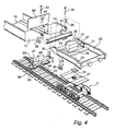
Fig. 4 is an exploded view which schematically illustrates an end of an embodiment of the railway wagon according to the invention; -
Figs 5-8 are schematic perspective views illustrating different embodiments of supporting devices included in the railway wagon according to the invention; -
Figs 9a, 9b, 10-13 are schematic perspective views illustrating different embodiments of abutment devices according to the invention; and -
Figs 14-15 are schematic top plan views of different loading/unloading positions. - The invention concerns a railway wagon which is designed for the modern concept of loading and unloading of entire vehicles.
Figs 1 and 2 illustrate precisely a railway wagon 1 which carries atruck 2.Fig. 2 shows the principle of construction which enables the concept. The railway wagon comprises aload carrier 3, which is releasably connected to front andrear bogies 5, 7. When loading of a vehicle, for instance a truck, is to occur, one/the front end of theload carrier 3 is released and displaced, in this case by being pivoted on a pivot which is positioned at its other/rear end, relative to thebogie 3. Acrossbar 9, which is included in a tilt-preventing device which will be described in more detail below, is released at its one end and pivoted away. Then the vehicle can drive up on theload carrier 3, after which the load carrier is returned to the initial position and locked.Fig. 14 shows that the other end of theload carrier 3 can also be pivoted outwards in a corresponding manner.Fig. 15 illustrates another alternative loading and unloading position, where both ends of theload carrier 3 have been displaced to the same side so that the load carrier is positioned beside the bogies parallel to the railway track. - As shown in
Fig. 4 , theload carrier 3 has two spaced-apart oppositelateral beams bottom part 15 constitutes the actual loading surface on which thevehicle 2 is received. To enable safe displacement of theload carrier 3 in relation to therespective bogies 5, 7, the railway wagon 1 is equipped in the following way. It should first be emphasised that both ends of the railway wagon 1 preferably, and in any case in this embodiment, are identically constructed. Therefore only one end will be considered. At the bottom, there is thebogie 5 in contact with the rails via the wheels. Anintermediate part 17 is arranged on top of the bogie. Theintermediate part 17 is pivotally connected to the bogie by means of apivot projection 19 which is lowered into aseat 21 in the bogie. The intermediate part is provided with connecting means (not shown) for connecting the wagon 1 to another wagon or an engine in a generally known manner. Theintermediate part 17 is further provided withframe side members guideway 27. Parallel to the guideway, a displacing driving device extends, comprising afeeder 28, which is supported by two cooperating piston-and-cylinder assemblies Fig. 3 ), which extends between the ends of the lateral beams 11, 13 and is releasably and hingedly connected to the same. In a transport position, when the wagon 1 is to be run on the rail, theload carrier 3 is connected to theintermediate part 17, connectingprojections frame side members recesses crossbar 9 extends parallel to theguideway 27 and rests on the same, or is arranged with a small clearance to the same. First locking means 33, 34 lock the lateral beams 11, 13 in relation to theframe side members crossbar 9 to the lateral beams. The locking beams can be, for instance, hydraulically controlled and are greatly simplified in the Figure. A portion of afeeding beam 43, which is an elongate projecting portion of thecrossbar 9, extending along thecrossbar 9, is inserted into a recess 45 in thefeeder 28. - Two supporting
devices load carrier 3. The supporting devices are identical but mirror-inverted. Only one of them will therefore be described in more detail. The supportingdevice 47 comprises anoperating arm 51, an operatingdevice 53 and anabutment device 55. The operatingdevice 53 is mounted on the inside of thelateral beam 11. Oneend 57 of theoperating arm 51 is hingedly connected to the front end of thebottom part 15 in the centre of thebottom part 15 and itsother end 59 is hingedly connected to the operatingdevice 53. Theabutment device 55 is mounted on theoperating arm 51 between itsends - As is best seen in
Fig. 5 , theabutment device 55 comprises asupport 61, whose one end is connected to theoperating arm 51 and whose other end constitutes an attachment for a slidingmember 63 which is ski-shaped, and two supportingwheels member 63 is hingedly connected to thesupport 61 and the supportingwheels support 61. The slidingmember 63 is formed with twoopenings wheels Fig. 9a . The supportingwheels member 63. The supportingwheels member 63 substantially does not abut against the base. At the same time the supportingwheels wheels member 63 comes into abutment against the base. - The operating
device 53 is a piston-and-cylinder assembly which is adapted to lower and raise theouter end 59 of theoperating arm 51 and thereby rotate the same about theother end 57. As a result, theabutment device 55 is vertically displaced. -
Fig. 7 illustrates schematically an alternative embodiment where the operating devices 54' are arranged on the outside of the lateral beams. - The displacement of the
load carrier 3 in relation to thebogie 5 from the transport position to the position for loading and unloading is performed in the following manner. First the locking means 33, 34 are released so that theload carrier 3 is movable in relation to theintermediate part 17. Subsequently the end of theload carrier 3 is driven out a distance by thefeeder 28 being moved in the lateral direction by means of the piston-and-cylinder assemblies feeder 28 is, by means of one or more engaging pins which are inserted into holes in thefeeding beam 43, in engagement with thefeeding beam 43 on thecrossbar 9 and pulls the same along in its movement. Once the end of theload carrier 3 has been displaced, in this embodiment has been pivoted outwards, so far that the abutment device is positioned outside the rail, the abutment device is lowered into abutment against the base by means of the operatingdevice 53, seeFig. 3a . Theabutment device 55 is driven down so as to take over a considerable part of the weight of theload carrier 3 from thecrossbar 9. Thefeeder 28 then continues to drive out the end of theload carrier 3. During this movement, the supportingwheels feeder 28 is released from thefeeding beam 43 and returned in order to engage in a new hole in thefeeding beam 43. At the end of the displacement, when thefeeder 28 is engaged with thefeeding beam 43 in an outermost hole in the same and thecrossbar 9 is on its way to leave the guideway completely, thesecond abutment device 56 is lowered to the ground, seeFig. 3b , so that theload carrier 3 can be displaced the last distance until the end of thelateral beam 13 reaches the end of theintermediate part 17. Subsequently one end of thecrossbar 9 is released so that thecrossbar 9 can be pivoted away and an unloading andloading ramp 69 is lowered, seeFig. 3c . It would otherwise be in the way of the vehicle that is to drive on to/off theload carrier 3, seeFig. 3d . When theload carrier 3 is to be returned to the transport position, the above-described operations are performed in reverse order. - An embodiment of the railway wagon according to the invention has been described above but should not be considered limitative. Many modifications are feasible within the scope of the invention as defined by the claims. A few examples of such modifications will be given below.
- Some alternative embodiments of the abutment device are illustrated highly schematically in
Figs 9a, 9b, 10-13 . Thus the abutment device has in one variant a supportingwheel 71 which projects through anopening 73 in the slidingmember 75. In another variant, it has two juxtaposed slidingmembers 81, 83 which cooperate each with a supportingwheel member 103. In another alternative embodiment, seeFig. 11 , the opening in the slidingmember 111 is provided by the sliding member being divided into twoseparate portions wheel 117 is arranged. In its very simplest design, the abutment device comprises only the sliding member and the attachment therefor, while there is no supporting wheel. However, it is a considerable advantage to have also supporting wheels which significantly reduce the friction on hard bases. In another variant, the supporting device comprises a drive unit, such as a hydraulic engine or some other drive source, which drives the supporting wheel, or the respective supporting wheels directly. The drive unit can be used to perform on its own the displacement of the load carrier, but can also be used as an auxiliary drive unit for the displacing driving device. - Moreover, many modifications of the supporting device as a whole are conceivable. An alternative embodiment thereof is illustrated in
Fig. 6 . In this embodiment, there are no operating arms. Theabutment device 607 is instead directly mounted on a part of theoperating device device lateral beam cylinder assembly abutment device 607 is connected to thepiston 606.Fig. 8 illustrates an alternative where the supporting device 603' is mounted on the outside of the lateral beam. - The devices that are shown in the examples above as piston-and-cylinder assemblies can be formed by other techniques that afford the corresponding function.
- The displacement of the load carrier can be performed in various ways, for example by a chain feeder, a screw feeder etc.
- Furthermore the tilt-preventing device consists in an alternative embodiment of
props 36 which are arranged on each side of the respectiveintermediate parts 17. For the sake of simplicity, one of the props is shown inFig. 4 , although this primarily illustrates another embodiment of the railway wagon with the above-described variant of the tilt-preventing device. However, there is nothing to prevent a combination of these as illustrated inFig. 4 , thereby achieving a still more reliable construction. Theprop 36 is connected to theframe side member 23 and is to be extended to allow its free end to come into abutment against the base. - In an alternative embodiment, the crossbar is omitted. The end of the lateral beam moving over the intermediate part then slides on the guideway. The end can be provided with a roll which rolls on the guideway. In a return operation, the embodiment involving the crossbar has, however, the advantage that the crossbar guides the end of the outer lateral beam upwards if it should be positioned under the connecting projection of the frame side member. To prevent this situation, it would be conceivable to arrange an automatic level control of the supporting device.
Claims (14)
- A railway wagon comprising a load carrier (3) and front and rear bogies (5,7), the load carrier being releasably connected to the respective bogies, and laterally displaceable in relation to the respective bogies, the load carrier having a front and a rear end and being at each end provided with a supporting device (47), which supports the load carrier in a position where it is displaced in relation to the bogie, wherein the railway waggon comprises, at each end of the load carrier, a displacing driving device (28) for displacing the load carrier relative to the bogie, at least along an initial displacement distance, and a tilt-preventing device (9), which is adapted to counteract, at least during part of the displacement, tilting tendencies of the load carrier, characterised in that each supporting device comprises an abutment device (55) which is vertically operable between a pulled-up position and an extended position, in which the abutment device abuts against a base, and each abutment device comprises a sliding member (63), which is adapted to abut against the base in the extended position.
- A railway wagon as claimed in claim 1, wherein each abutment device (55) further comprises a supporting wheel (65), a portion of the supporting wheel at least in the extended position extending below an underside of the sliding member (63).
- A railway wagon as claimed in claim 1, wherein the abutment device (55) further comprises a supporting wheel (101) which is displaceable relative to the sliding member (103), between a position in which a portion of the supporting wheel in the extended position extends below an underside of the sliding member and a position in which the entire supporting wheel is positioned above said underside in the extended position.
- A railway wagon as claimed in claim 2 or 3, wherein the sliding member (63, 103) is formed with an opening to be passed by said portion of the supporting wheel.
- A railway wagon as claimed in any one of the preceding claims, wherein the abutment device (55) comprises a plurality of supporting wheels (65, 66).
- A railway wagon as claimed in any one of the preceding claims, wherein the sliding member (63) is ski-shaped.
- A railway wagon as claimed in any one of the preceding claims, wherein the abutment device (55) comprises a plurality of sliding members (83, 85) which are arranged side by side.
- A railway wagon as claimed in any one of the preceding claims, wherein the supporting device (47) comprises an operating device (53), to which the abutment device (55) is connected to be operated.
- A railway wagon as claimed in claim 8, wherein the load carrier (3) comprises a lateral beam (11) to which the operating device (53) is connected.
- A railway wagon as claimed claim 9, wherein the entire supporting device (47) is attached to the lateral beam (11).
- A railway wagon as claimed in claim 10, wherein the abutment device (55) is directly mounted on a vertically movable part of the operating device.
- A railway wagon as claimed in claim 9, wherein the supporting device (47) further comprises an operating arm (51) to one end of which the operating device (53) is connected, for operation of the same, and the other end of which is rotatably mounted in a fastening portion of the load carrier, the operating arm having an extent in the lateral direction of the load carrier and the abutment device being connected to the operating arm between the ends thereof.
- A railway wagon as claimed in any one of the preceding claims, wherein two supporting devices (47, 49) are arranged at each end of the load carrier.
- A railway wagon as claimed in any one of the preceding claims, wherein the load carrier has lateral beams (11, 13), which are arranged on opposite sides of the load carrier, and each tilt-preventing device comprises a crossbar (9) which extends between the lateral beams at the ends thereof and which is movably and releasably connected to the bogie (5) via a connecting portion, the crossbar being adapted to rest against the connecting portion at least along the initial displacement distance.
Applications Claiming Priority (2)
| Application Number | Priority Date | Filing Date | Title |
|---|---|---|---|
| SE0402269A SE527117C2 (en) | 2004-09-17 | 2004-09-17 | Railway wagon |
| PCT/SE2005/001312 WO2006031178A1 (en) | 2004-09-17 | 2005-09-12 | Railway wagon |
Publications (2)
| Publication Number | Publication Date |
|---|---|
| EP1805072A1 EP1805072A1 (en) | 2007-07-11 |
| EP1805072B1 true EP1805072B1 (en) | 2011-04-06 |
Family
ID=33308781
Family Applications (1)
| Application Number | Title | Priority Date | Filing Date |
|---|---|---|---|
| EP05779092A Expired - Lifetime EP1805072B1 (en) | 2004-09-17 | 2005-09-12 | Railway wagon |
Country Status (9)
| Country | Link |
|---|---|
| US (1) | US7650844B2 (en) |
| EP (1) | EP1805072B1 (en) |
| CN (1) | CN100488819C (en) |
| AT (1) | ATE504480T1 (en) |
| BR (1) | BRPI0515359A (en) |
| DE (1) | DE602005027377D1 (en) |
| RU (1) | RU2356767C2 (en) |
| SE (1) | SE527117C2 (en) |
| WO (1) | WO2006031178A1 (en) |
Cited By (1)
| Publication number | Priority date | Publication date | Assignee | Title |
|---|---|---|---|---|
| WO2012177216A1 (en) * | 2011-06-21 | 2012-12-27 | Flexiwaggon Ab | Support device for a laterally displaceable railway waggon |
Families Citing this family (17)
| Publication number | Priority date | Publication date | Assignee | Title |
|---|---|---|---|---|
| SE527117C2 (en) * | 2004-09-17 | 2005-12-27 | Je Utveckling O Foervaltning A | Railway wagon |
| US8113121B2 (en) * | 2007-10-10 | 2012-02-14 | The Texas A&M University System | Guideway system to roadway interchange system |
| KR101757893B1 (en) * | 2009-04-16 | 2017-07-14 | 헬롬 리미티드 | A railway wagon and a method of its loading |
| FR2960843B1 (en) * | 2010-06-04 | 2017-10-20 | Lohr Ind | TRANSPORT WAGON HAVING A COMPENSATION INTERFACE ABOVE THE GROUND AND THIS MAINLY BASED ON THE WEIGHT OF THE LOAD TO BE TRANSPORTED |
| FR2986204B1 (en) * | 2012-01-27 | 2015-03-06 | Lohr Ind | ASSEMBLY FOR LOADING AND UNLOADING SEMI-TRAILERS ON RAILWAY CARS. |
| CN104859671B (en) * | 2015-06-12 | 2017-12-19 | 中车齐齐哈尔车辆有限公司 | Piggyback transport car |
| ES2774413T3 (en) | 2015-12-11 | 2020-07-21 | Flexiwaggon Ab | Suspension device for cables and pipes |
| CN105539471A (en) * | 2015-12-24 | 2016-05-04 | 安徽理工大学 | Intelligent tramcar capable of achieving partite transport and paying according to work |
| DE102017004577A1 (en) * | 2017-05-12 | 2018-11-15 | Franz Bartos | CAR-TRANS-WAGON Low-floor wagon mainly for road vehicles |
| PL237854B1 (en) * | 2018-03-15 | 2021-06-14 | Inst Pojazdow Szynowych Tabor | Railway carriage for the rail-road combined transport system |
| CN108944969B (en) * | 2018-06-22 | 2019-07-23 | 中车石家庄车辆有限公司 | Railroad platform vehicle and railroad train |
| RU2700100C1 (en) * | 2018-07-13 | 2019-09-12 | Андрей Валентинович Жакалов | Piggy-back car |
| CN116803815A (en) | 2018-10-24 | 2023-09-26 | 赫尔罗姆有限责任公司 | Railway wagons used for transporting semi-trailers and the like |
| RU2698530C1 (en) * | 2018-12-26 | 2019-08-28 | Андрей Валентинович Жакалов | Piggyback car |
| ES2977187T3 (en) * | 2019-05-29 | 2024-08-20 | Flexiwaggon Ab | A side-moving railway car |
| EP4371841A1 (en) * | 2022-11-15 | 2024-05-22 | Helrom GmbH | Railway wagon with improved launch beam positioning |
| WO2025098631A1 (en) * | 2023-11-10 | 2025-05-15 | Flexiwaggon Ab | A railway wagon |
Family Cites Families (38)
| Publication number | Priority date | Publication date | Assignee | Title |
|---|---|---|---|---|
| US1968196A (en) * | 1931-12-03 | 1934-07-31 | Mechanical Handling Sys Inc | System for loading and unloading trailers from railroad cars |
| US2614857A (en) * | 1949-10-18 | 1952-10-21 | Mathisen Arne Lars | Vehicle |
| US2933053A (en) * | 1957-05-28 | 1960-04-19 | Flexi Van Inc | Railway car for transporting trailer bodies |
| US3019917A (en) * | 1957-06-26 | 1962-02-06 | Albert I Kegan | Mobile loading ramps |
| US3352438A (en) * | 1965-06-11 | 1967-11-14 | Robert E Davidson | Transportation system and method |
| US3516368A (en) * | 1967-09-27 | 1970-06-23 | Blaw Knox Co | Self-loading and unloading railroad car |
| US3581918A (en) * | 1968-01-12 | 1971-06-01 | Fruehauf Corp | Railcar-unloading system |
| US3504921A (en) * | 1968-04-08 | 1970-04-07 | Lawrence R Osmond | Ski carrying means |
| US3487437A (en) * | 1968-06-17 | 1969-12-30 | Clarence F Meskan | Snowmobile with stabilizing means |
| US3884158A (en) * | 1973-10-29 | 1975-05-20 | James A Rumell | Railroad car with hydraulically actuated turntable |
| US3916799A (en) * | 1974-12-05 | 1975-11-04 | Allen E Smith | Rail car with swing platform and vertical position fixing means |
| US4129079A (en) * | 1977-07-07 | 1978-12-12 | Shannon Montague W | Railroad car for highway trailers |
| US4167270A (en) * | 1977-12-30 | 1979-09-11 | Laplaca Paul | Recreational vehicle skid support |
| SU870235A1 (en) | 1980-01-11 | 1981-10-07 | Уральский лесотехнический институт им.Ленинского комсомола | Trailer |
| EP0064053A1 (en) | 1980-02-01 | 1982-11-10 | BEHRENS, Claus-Peter | Wagon with lowered platform for the railway transport of motor vehicles and giant containers |
| DE3234374C2 (en) | 1982-09-16 | 1985-04-25 | Waggonfabrik Talbot, 5100 Aachen | Rail freight wagons for transporting road vehicles |
| NL8501911A (en) * | 1985-07-04 | 1987-02-02 | Fedde Walda Nanne Marcel Walda | FOUR-BUFFER PRESSURE LOCKING AND STARMAKING SLIDE-IN FOR A LOW-LOADING WAGON WITH A ROTATING FLOOR, AND AN ELECTRICAL DRIVE OF THE ROTATING FLOOR. |
| NL8501912A (en) * | 1985-07-04 | 1987-02-02 | Fedde Walda Nanne Marcel Walda | SIDE LEVEL ROLLERS ON A LOW-LOADER WITH SWIVEL FLOOR T.B.V. FAST LOADING AND UNLOADING OF TRAILERS. |
| GB2179311B (en) * | 1985-07-04 | 1989-05-10 | Robert Malcolm Ord | Rail vehicle for transporting road semi-trailers |
| NL8800161A (en) * | 1988-01-25 | 1989-08-16 | Ark Bv De | TURNTABLE FOR A RAIL VEHICLE. |
| US4946324A (en) * | 1989-01-13 | 1990-08-07 | Consolidated Rail Corporation | Railroad flatcar with turntable |
| FI82650C (en) * | 1989-06-21 | 1991-04-10 | Rautaruukki Oy | Support boom in a means of transport |
| FR2675452B1 (en) * | 1991-04-19 | 1993-12-17 | Marrel Bennes | WAGON BAG HOLDER WITH WAGON-BERCE LOCKING. |
| AT398993B (en) * | 1992-03-16 | 1995-02-27 | Plasser Bahnbaumasch Franz | TRANSPORT TROLLEYS WITH A TROLLEY FRAME BASED ON RAIL TROLLEY |
| IT1266316B1 (en) | 1993-04-29 | 1996-12-27 | Immobiliare Varcas Spa | IMPROVEMENT OF A RAILWAY WAGON FOR THE STORAGE AND TRANSPORT OF INDUSTRIAL ROAD VEHICLES. |
| CN1156432A (en) * | 1994-08-22 | 1997-08-06 | 小亚历山大·法勒 | Method and apparatus for cargo forwarding |
| SE9403544D0 (en) | 1994-10-18 | 1994-10-18 | Lars Berglund | Method and apparatus for loading and unloading freight trains |
| SE503925C2 (en) * | 1995-05-26 | 1996-09-30 | Jan Eriksson | Railway wagon |
| DE19546300C1 (en) | 1995-10-04 | 1997-04-30 | Matthias Gradenwitz | Loading and unloading freight vehicles from a railway train |
| US6279483B1 (en) * | 1996-11-04 | 2001-08-28 | Railroad Technologies Pty. Ltd. | Rail/road transport |
| US5911422A (en) * | 1997-10-02 | 1999-06-15 | Carpenter; Jeff | Recreational wheeled accessory carrier |
| AU2001261659A1 (en) * | 2000-05-15 | 2001-11-26 | Asc Group Inc. | Road-rail adaptive vehicle transit system |
| FR2810609B1 (en) * | 2000-06-21 | 2002-12-27 | Lohr Ind | WAGON FOR COMBINED RAIL / ROAD TRANSPORT COMPRISING TWO END PLATFORMS SUPPORTING A PIVOTING RAIL STRUCTURE CARRYING THE ROAD LOAD |
| FR2810612B1 (en) * | 2000-06-23 | 2002-10-04 | Lohr Ind | SYSTEM FOR TRANSPORTING AND LOADING / UNLOADING OBLICATED WAGONS IN A RAIL / ROAD RAIL TRANSPORT RAILWAY AND METHOD OF IMPLEMENTING SAME |
| FR2815316B1 (en) * | 2000-10-17 | 2002-12-27 | Lohr Ind | PIVOTING SUPPORT BASE FOR THE PIVOTING CARRIER STRUCTURE OF A COMBINED RAIL / ROAD TRANSPORT WAGON |
| SE523922C2 (en) | 2002-09-09 | 2004-06-01 | Novatrain Ab | Device and method for facilitating loading / unloading of a rail freight conveyor |
| SE527117C2 (en) * | 2004-09-17 | 2005-12-27 | Je Utveckling O Foervaltning A | Railway wagon |
| US20070025831A1 (en) * | 2005-07-29 | 2007-02-01 | Barry Burt | Rail car loading apparatus |
-
2004
- 2004-09-17 SE SE0402269A patent/SE527117C2/en not_active IP Right Cessation
-
2005
- 2005-09-12 AT AT05779092T patent/ATE504480T1/en not_active IP Right Cessation
- 2005-09-12 WO PCT/SE2005/001312 patent/WO2006031178A1/en not_active Ceased
- 2005-09-12 DE DE602005027377T patent/DE602005027377D1/en not_active Expired - Lifetime
- 2005-09-12 CN CNB2005800311601A patent/CN100488819C/en not_active Expired - Fee Related
- 2005-09-12 BR BRPI0515359-0A patent/BRPI0515359A/en not_active IP Right Cessation
- 2005-09-12 EP EP05779092A patent/EP1805072B1/en not_active Expired - Lifetime
- 2005-09-12 RU RU2007114272/11A patent/RU2356767C2/en not_active IP Right Cessation
- 2005-09-12 US US11/663,004 patent/US7650844B2/en not_active Expired - Fee Related
Cited By (1)
| Publication number | Priority date | Publication date | Assignee | Title |
|---|---|---|---|---|
| WO2012177216A1 (en) * | 2011-06-21 | 2012-12-27 | Flexiwaggon Ab | Support device for a laterally displaceable railway waggon |
Also Published As
| Publication number | Publication date |
|---|---|
| EP1805072A1 (en) | 2007-07-11 |
| ATE504480T1 (en) | 2011-04-15 |
| SE0402269D0 (en) | 2004-09-17 |
| RU2356767C2 (en) | 2009-05-27 |
| SE0402269L (en) | 2005-12-27 |
| WO2006031178A1 (en) | 2006-03-23 |
| RU2007114272A (en) | 2008-10-27 |
| US7650844B2 (en) | 2010-01-26 |
| SE527117C2 (en) | 2005-12-27 |
| CN100488819C (en) | 2009-05-20 |
| WO2006031178A9 (en) | 2006-06-01 |
| CN101027210A (en) | 2007-08-29 |
| DE602005027377D1 (en) | 2011-05-19 |
| US20080271634A1 (en) | 2008-11-06 |
| BRPI0515359A (en) | 2008-07-15 |
Similar Documents
| Publication | Publication Date | Title |
|---|---|---|
| US7650844B2 (en) | Railway wagon | |
| JP6688435B2 (en) | Scissor lift for vehicle | |
| CA2317850C (en) | Low-profile truck leveler | |
| JP5394382B2 (en) | Device to fix the container on the base of the transport vehicle | |
| EP3942116B1 (en) | Vehicle comprising a stabilizer, and stabilizer for such a vehicle | |
| JPH09500590A (en) | Transport vehicles for unloading and unloading containers and the like to and from loading platforms | |
| EP2723619B1 (en) | Support device for a laterally displaceable railway waggon | |
| EP2374682B1 (en) | Swivel frame, and rail vehicle | |
| US6962473B2 (en) | Apparatus for transferring containers and flat racks from a truck to a trailer | |
| US7438515B2 (en) | Container dump truck and oblique transfer system | |
| US3208615A (en) | Flat bed trailer | |
| JPS61166436A (en) | Freight delivery bridging device for pit | |
| GB2329627A (en) | Support for layers of welded rails | |
| JP5517703B2 (en) | Fall prevention stopper for floor plate such as tailgate | |
| CN114945532A (en) | Inclined scissor lift for vehicle | |
| JP2007112346A (en) | Sliding type roof carrier | |
| JP2951579B2 (en) | lift device | |
| AU2001100269A4 (en) | Roll-back body vehicles | |
| GB2538100A (en) | A tail lift | |
| RU145967U1 (en) | FLEXIBLE ROLLING SHOE | |
| JPH11503683A (en) | Emergency braking device for trucks | |
| JP2009120168A (en) | Container trailer |
Legal Events
| Date | Code | Title | Description |
|---|---|---|---|
| PUAI | Public reference made under article 153(3) epc to a published international application that has entered the european phase |
Free format text: ORIGINAL CODE: 0009012 |
|
| 17P | Request for examination filed |
Effective date: 20070413 |
|
| AK | Designated contracting states |
Kind code of ref document: A1 Designated state(s): AT BE BG CH CY CZ DE DK EE ES FI FR GB GR HU IE IS IT LI LT LU LV MC NL PL PT RO SE SI SK TR |
|
| DAX | Request for extension of the european patent (deleted) | ||
| 17Q | First examination report despatched |
Effective date: 20090209 |
|
| RAP1 | Party data changed (applicant data changed or rights of an application transferred) |
Owner name: FLEXIWAGGON AB |
|
| GRAP | Despatch of communication of intention to grant a patent |
Free format text: ORIGINAL CODE: EPIDOSNIGR1 |
|
| GRAS | Grant fee paid |
Free format text: ORIGINAL CODE: EPIDOSNIGR3 |
|
| GRAA | (expected) grant |
Free format text: ORIGINAL CODE: 0009210 |
|
| AK | Designated contracting states |
Kind code of ref document: B1 Designated state(s): AT BE BG CH CY CZ DE DK EE ES FI FR GB GR HU IE IS IT LI LT LU LV MC NL PL PT RO SE SI SK TR |
|
| REG | Reference to a national code |
Ref country code: GB Ref legal event code: FG4D |
|
| REG | Reference to a national code |
Ref country code: CH Ref legal event code: EP |
|
| REG | Reference to a national code |
Ref country code: IE Ref legal event code: FG4D |
|
| REF | Corresponds to: |
Ref document number: 602005027377 Country of ref document: DE Date of ref document: 20110519 Kind code of ref document: P |
|
| REG | Reference to a national code |
Ref country code: DE Ref legal event code: R096 Ref document number: 602005027377 Country of ref document: DE Effective date: 20110519 |
|
| REG | Reference to a national code |
Ref country code: CH Ref legal event code: NV Representative=s name: OFFICE ERNEST T. FREYLINGER S.A. |
|
| REG | Reference to a national code |
Ref country code: NL Ref legal event code: VDEP Effective date: 20110406 |
|
| PG25 | Lapsed in a contracting state [announced via postgrant information from national office to epo] |
Ref country code: SI Free format text: LAPSE BECAUSE OF FAILURE TO SUBMIT A TRANSLATION OF THE DESCRIPTION OR TO PAY THE FEE WITHIN THE PRESCRIBED TIME-LIMIT Effective date: 20110406 |
|
| LTIE | Lt: invalidation of european patent or patent extension |
Effective date: 20110406 |
|
| PG25 | Lapsed in a contracting state [announced via postgrant information from national office to epo] |
Ref country code: LT Free format text: LAPSE BECAUSE OF FAILURE TO SUBMIT A TRANSLATION OF THE DESCRIPTION OR TO PAY THE FEE WITHIN THE PRESCRIBED TIME-LIMIT Effective date: 20110406 Ref country code: PT Free format text: LAPSE BECAUSE OF FAILURE TO SUBMIT A TRANSLATION OF THE DESCRIPTION OR TO PAY THE FEE WITHIN THE PRESCRIBED TIME-LIMIT Effective date: 20110808 Ref country code: SE Free format text: LAPSE BECAUSE OF FAILURE TO SUBMIT A TRANSLATION OF THE DESCRIPTION OR TO PAY THE FEE WITHIN THE PRESCRIBED TIME-LIMIT Effective date: 20110406 |
|
| PG25 | Lapsed in a contracting state [announced via postgrant information from national office to epo] |
Ref country code: FI Free format text: LAPSE BECAUSE OF FAILURE TO SUBMIT A TRANSLATION OF THE DESCRIPTION OR TO PAY THE FEE WITHIN THE PRESCRIBED TIME-LIMIT Effective date: 20110406 Ref country code: ES Free format text: LAPSE BECAUSE OF FAILURE TO SUBMIT A TRANSLATION OF THE DESCRIPTION OR TO PAY THE FEE WITHIN THE PRESCRIBED TIME-LIMIT Effective date: 20110717 Ref country code: CY Free format text: LAPSE BECAUSE OF FAILURE TO SUBMIT A TRANSLATION OF THE DESCRIPTION OR TO PAY THE FEE WITHIN THE PRESCRIBED TIME-LIMIT Effective date: 20110406 Ref country code: IS Free format text: LAPSE BECAUSE OF FAILURE TO SUBMIT A TRANSLATION OF THE DESCRIPTION OR TO PAY THE FEE WITHIN THE PRESCRIBED TIME-LIMIT Effective date: 20110806 Ref country code: GR Free format text: LAPSE BECAUSE OF FAILURE TO SUBMIT A TRANSLATION OF THE DESCRIPTION OR TO PAY THE FEE WITHIN THE PRESCRIBED TIME-LIMIT Effective date: 20110707 Ref country code: LV Free format text: LAPSE BECAUSE OF FAILURE TO SUBMIT A TRANSLATION OF THE DESCRIPTION OR TO PAY THE FEE WITHIN THE PRESCRIBED TIME-LIMIT Effective date: 20110406 Ref country code: AT Free format text: LAPSE BECAUSE OF FAILURE TO SUBMIT A TRANSLATION OF THE DESCRIPTION OR TO PAY THE FEE WITHIN THE PRESCRIBED TIME-LIMIT Effective date: 20110406 Ref country code: BE Free format text: LAPSE BECAUSE OF FAILURE TO SUBMIT A TRANSLATION OF THE DESCRIPTION OR TO PAY THE FEE WITHIN THE PRESCRIBED TIME-LIMIT Effective date: 20110406 |
|
| PG25 | Lapsed in a contracting state [announced via postgrant information from national office to epo] |
Ref country code: NL Free format text: LAPSE BECAUSE OF FAILURE TO SUBMIT A TRANSLATION OF THE DESCRIPTION OR TO PAY THE FEE WITHIN THE PRESCRIBED TIME-LIMIT Effective date: 20110406 |
|
| PG25 | Lapsed in a contracting state [announced via postgrant information from national office to epo] |
Ref country code: EE Free format text: LAPSE BECAUSE OF FAILURE TO SUBMIT A TRANSLATION OF THE DESCRIPTION OR TO PAY THE FEE WITHIN THE PRESCRIBED TIME-LIMIT Effective date: 20110406 Ref country code: CZ Free format text: LAPSE BECAUSE OF FAILURE TO SUBMIT A TRANSLATION OF THE DESCRIPTION OR TO PAY THE FEE WITHIN THE PRESCRIBED TIME-LIMIT Effective date: 20110406 |
|
| PLBE | No opposition filed within time limit |
Free format text: ORIGINAL CODE: 0009261 |
|
| STAA | Information on the status of an ep patent application or granted ep patent |
Free format text: STATUS: NO OPPOSITION FILED WITHIN TIME LIMIT |
|
| PG25 | Lapsed in a contracting state [announced via postgrant information from national office to epo] |
Ref country code: RO Free format text: LAPSE BECAUSE OF FAILURE TO SUBMIT A TRANSLATION OF THE DESCRIPTION OR TO PAY THE FEE WITHIN THE PRESCRIBED TIME-LIMIT Effective date: 20110406 Ref country code: DK Free format text: LAPSE BECAUSE OF FAILURE TO SUBMIT A TRANSLATION OF THE DESCRIPTION OR TO PAY THE FEE WITHIN THE PRESCRIBED TIME-LIMIT Effective date: 20110406 Ref country code: PL Free format text: LAPSE BECAUSE OF FAILURE TO SUBMIT A TRANSLATION OF THE DESCRIPTION OR TO PAY THE FEE WITHIN THE PRESCRIBED TIME-LIMIT Effective date: 20110406 Ref country code: SK Free format text: LAPSE BECAUSE OF FAILURE TO SUBMIT A TRANSLATION OF THE DESCRIPTION OR TO PAY THE FEE WITHIN THE PRESCRIBED TIME-LIMIT Effective date: 20110406 |
|
| 26N | No opposition filed |
Effective date: 20120110 |
|
| PG25 | Lapsed in a contracting state [announced via postgrant information from national office to epo] |
Ref country code: MC Free format text: LAPSE BECAUSE OF NON-PAYMENT OF DUE FEES Effective date: 20110930 |
|
| REG | Reference to a national code |
Ref country code: DE Ref legal event code: R097 Ref document number: 602005027377 Country of ref document: DE Effective date: 20120110 |
|
| REG | Reference to a national code |
Ref country code: IE Ref legal event code: MM4A |
|
| PG25 | Lapsed in a contracting state [announced via postgrant information from national office to epo] |
Ref country code: IE Free format text: LAPSE BECAUSE OF NON-PAYMENT OF DUE FEES Effective date: 20110912 |
|
| PG25 | Lapsed in a contracting state [announced via postgrant information from national office to epo] |
Ref country code: LU Free format text: LAPSE BECAUSE OF NON-PAYMENT OF DUE FEES Effective date: 20110912 |
|
| PG25 | Lapsed in a contracting state [announced via postgrant information from national office to epo] |
Ref country code: BG Free format text: LAPSE BECAUSE OF FAILURE TO SUBMIT A TRANSLATION OF THE DESCRIPTION OR TO PAY THE FEE WITHIN THE PRESCRIBED TIME-LIMIT Effective date: 20110706 |
|
| PG25 | Lapsed in a contracting state [announced via postgrant information from national office to epo] |
Ref country code: TR Free format text: LAPSE BECAUSE OF FAILURE TO SUBMIT A TRANSLATION OF THE DESCRIPTION OR TO PAY THE FEE WITHIN THE PRESCRIBED TIME-LIMIT Effective date: 20110406 |
|
| PG25 | Lapsed in a contracting state [announced via postgrant information from national office to epo] |
Ref country code: HU Free format text: LAPSE BECAUSE OF FAILURE TO SUBMIT A TRANSLATION OF THE DESCRIPTION OR TO PAY THE FEE WITHIN THE PRESCRIBED TIME-LIMIT Effective date: 20110406 |
|
| PG25 | Lapsed in a contracting state [announced via postgrant information from national office to epo] |
Ref country code: IT Free format text: LAPSE BECAUSE OF FAILURE TO SUBMIT A TRANSLATION OF THE DESCRIPTION OR TO PAY THE FEE WITHIN THE PRESCRIBED TIME-LIMIT Effective date: 20110406 |
|
| PGFP | Annual fee paid to national office [announced via postgrant information from national office to epo] |
Ref country code: DE Payment date: 20140903 Year of fee payment: 10 Ref country code: CH Payment date: 20140905 Year of fee payment: 10 |
|
| PGFP | Annual fee paid to national office [announced via postgrant information from national office to epo] |
Ref country code: GB Payment date: 20140904 Year of fee payment: 10 |
|
| PGFP | Annual fee paid to national office [announced via postgrant information from national office to epo] |
Ref country code: FR Payment date: 20140911 Year of fee payment: 10 |
|
| REG | Reference to a national code |
Ref country code: DE Ref legal event code: R119 Ref document number: 602005027377 Country of ref document: DE |
|
| REG | Reference to a national code |
Ref country code: CH Ref legal event code: PL |
|
| GBPC | Gb: european patent ceased through non-payment of renewal fee |
Effective date: 20150912 |
|
| REG | Reference to a national code |
Ref country code: FR Ref legal event code: ST Effective date: 20160531 |
|
| PG25 | Lapsed in a contracting state [announced via postgrant information from national office to epo] |
Ref country code: GB Free format text: LAPSE BECAUSE OF NON-PAYMENT OF DUE FEES Effective date: 20150912 Ref country code: LI Free format text: LAPSE BECAUSE OF NON-PAYMENT OF DUE FEES Effective date: 20150930 Ref country code: CH Free format text: LAPSE BECAUSE OF NON-PAYMENT OF DUE FEES Effective date: 20150930 Ref country code: DE Free format text: LAPSE BECAUSE OF NON-PAYMENT OF DUE FEES Effective date: 20160401 |
|
| PG25 | Lapsed in a contracting state [announced via postgrant information from national office to epo] |
Ref country code: FR Free format text: LAPSE BECAUSE OF NON-PAYMENT OF DUE FEES Effective date: 20150930 |