EP1804451A2 - Appareil et procédé de détermination de trame pilote dans un système de communication par accès sans fil large bande - Google Patents
Appareil et procédé de détermination de trame pilote dans un système de communication par accès sans fil large bande Download PDFInfo
- Publication number
- EP1804451A2 EP1804451A2 EP06124823A EP06124823A EP1804451A2 EP 1804451 A2 EP1804451 A2 EP 1804451A2 EP 06124823 A EP06124823 A EP 06124823A EP 06124823 A EP06124823 A EP 06124823A EP 1804451 A2 EP1804451 A2 EP 1804451A2
- Authority
- EP
- European Patent Office
- Prior art keywords
- coherence
- time
- pilot pattern
- pilot
- calculating
- Prior art date
- Legal status (The legal status is an assumption and is not a legal conclusion. Google has not performed a legal analysis and makes no representation as to the accuracy of the status listed.)
- Granted
Links
Images


Classifications
-
- H—ELECTRICITY
- H04—ELECTRIC COMMUNICATION TECHNIQUE
- H04L—TRANSMISSION OF DIGITAL INFORMATION, e.g. TELEGRAPHIC COMMUNICATION
- H04L27/00—Modulated-carrier systems
- H04L27/26—Systems using multi-frequency codes
-
- H—ELECTRICITY
- H04—ELECTRIC COMMUNICATION TECHNIQUE
- H04L—TRANSMISSION OF DIGITAL INFORMATION, e.g. TELEGRAPHIC COMMUNICATION
- H04L27/00—Modulated-carrier systems
- H04L27/26—Systems using multi-frequency codes
- H04L27/2601—Multicarrier modulation systems
- H04L27/2602—Signal structure
- H04L27/261—Details of reference signals
-
- H—ELECTRICITY
- H04—ELECTRIC COMMUNICATION TECHNIQUE
- H04L—TRANSMISSION OF DIGITAL INFORMATION, e.g. TELEGRAPHIC COMMUNICATION
- H04L1/00—Arrangements for detecting or preventing errors in the information received
- H04L1/0001—Systems modifying transmission characteristics according to link quality, e.g. power backoff
-
- H—ELECTRICITY
- H04—ELECTRIC COMMUNICATION TECHNIQUE
- H04L—TRANSMISSION OF DIGITAL INFORMATION, e.g. TELEGRAPHIC COMMUNICATION
- H04L25/00—Baseband systems
- H04L25/02—Details ; arrangements for supplying electrical power along data transmission lines
- H04L25/0202—Channel estimation
- H04L25/0222—Estimation of channel variability, e.g. coherence bandwidth, coherence time, fading frequency
Definitions
- the present invention relates generally to a Broadband Wireless Access (BWA) communication system, and in particular, to an apparatus and method for adaptively changing a pilot pattern according to a link in an Orthogonal Frequency Division Multiplexing (OFDM) communication system.
- BWA Broadband Wireless Access
- OFDM Orthogonal Frequency Division Multiplexing
- OFDM is considered the most prominent future-generation wireless communication technology. It is expected that OFDM will be adopted for most wireless communication applications by the year 2010. OFDM has been adopted as a standard for an Institute of Electrical and Electronics Engineers (IEEE) 802.16 Wireless Metropolitan Area Network (WMAN) categorized into the 3.5 th Generation (3.5G) technology.
- IEEE Institute of Electrical and Electronics Engineers
- WMAN Wireless Metropolitan Area Network
- 3.5G 3.5 th Generation
- a transmitter simultaneously sends pilot subcarrier signals to a receiver with transmission of data subcarrier signals.
- the receiver performs synchronization acquisition, channel estimation, and Base Station (BS) identification using the pilot subcarrier signals.
- BS Base Station
- a transmission rule for sending the pilot subcarrier signals is known as "pilot pattern".
- the pilot pattern is determined in consideration of coherence bandwidth and coherence time.
- the coherence bandwidth is the maximum bandwidth over which a channel is relatively constant or non-distorting in the frequency domain
- the coherence time is the maximum time for which the channel is relatively constant in the time domain. Since the channel can be assumed to be constant over the coherence bandwidth for the coherence time, one pilot signal suffices for synchronization acquisition, channel estimation and BS identification.
- Radio channels are said to be a wide range of random channels and it is difficult to always ensure optimum performance over these random channels with the conventional fixed pilot pattern.
- a layout of pilot subcarriers affects performance according to the link status, which in turn directly influences channel estimation performance. That is, the channel estimation performance may increase according to the pilot pattern. Since the channel estimation performance has an influence on Bit Error Rate (BER), it is important to select a pilot pattern that minimizes channel estimation errors.
- BER Bit Error Rate
- An object of the present invention is to substantially solve at least the above problems and/or disadvantages and to provide at least the advantages below. Accordingly, an object of the present invention is to provide an apparatus and method for adaptively changing a pilot pattern according to a link in a BWA communication system.
- An object of the present invention is to provide an apparatus and method for selecting a pilot pattern that minimizes channel estimation errors in a BWA communication system.
- a further object of the present invention is to provide an apparatus and method for adaptively changing an uplink pilot pattern according to an uplink in a BWA communication system.
- Another object of the present invention is to provide an apparatus and method for selecting a pilot pattern based on the Mean Square Error (MSE) of frequency-domain data in a BWA communication system.
- MSE Mean Square Error
- an OFDM demodulator in an apparatus for determining a pilot pattern in a BWA communication system, generates frequency-domain data by fast-Fourier-transform (FFT)-processing a received signal.
- a pilot pattern decider calculates a coherence bandwidth and a coherence time using subcarrier values received from the OFDM demodulator, and selects one of a plurality of pilot patterns according to the ratio of the coherence bandwidth to the coherence time.
- subcarrier values are generated by FFT-processing a received signal.
- a coherence bandwidth and a coherence time are calculated using the subcarrier values.
- One of a plurality of pilot patterns is selected according to the ratio of the coherence bandwidth to the coherence time.
- FIG. 1 is a block diagram of a transmitter in a BWA communication system according to present invention.
- the transmitter is a relative concept, in that it is a Mobile Station (MS) on the uplink and a BS on the downlink.
- MS Mobile Station
- the transmitter includes a pilot pattern generator 100, an encoder 102, a modulator 104, a data mapper 106, a frame buffer 108, an OFDM modulator 110, a Digital-to-Analog Converter (DAC) 112 and a Radio Frequency (RF) processor 114.
- DAC Digital-to-Analog Converter
- RF Radio Frequency
- the encoder 102 encodes an input information bit stream at a coding rate and outputs the resulting coded bits or code symbols. With the number of the information bits being denoted by k and the coding rate being denoted by R, the number of the code symbols is k/R.
- the encoder 102 may be a convolutional encoder, a turbo encoder or a Low Density Parity Check (LDPC) encoder.
- LDPC Low Density Parity Check
- the modulator 104 generates complex symbols by mapping the coded symbols to signal points according to a modulation scheme or modulation level.
- the modulation scheme is one of Binary Phase Shift Keying (BPSK), Quadrature Phase Shift Keying (QPSK), 8-ary Phase Shift Keying (8PSK), 16-ary Quadrature Amplitude Modulation (16QAM) and 64QAM.
- BPSK Binary Phase Shift Keying
- QPSK Quadrature Phase Shift Keying
- 8PSK 8-ary Phase Shift Keying
- 16QAM 16-ary Quadrature Amplitude Modulation
- the data mapper 106 maps the complex symbols to subcarriers according to a control signal received from a higher layer and provides the mapped complex symbols to memory addresses in the frame buffer 108 of an actual frame size.
- the pilot pattern generator 100 selects a pilot pattern according to feedback information (i.e. pilot pattern selection information) received from a receiver and outputs pilot symbols to corresponding addresses of the frame buffer 108 according to the selected pilot pattern. For example, if a frame size is 64x64 and one frame delivers 64 pilot symbols, a 16x4 first pilot pattern and a 4x16 pilot pattern are available. According to the first pilot pattern, the pilot symbols are mapped equidistantly at an interval of 16 on the frequency axis and at an interval of 4 on the time axis. The second pilot pattern indicates that the pilot symbols are mapped equidistantly at an interval of 4 on the frequency axis and at an interval of 16 on the time axis. The first pilot pattern is viable when a coherence bandwidth is greater than a coherence time, while the second pilot pattern is used when the coherence time is greater than the coherence bandwidth.
- feedback information i.e. pilot pattern selection information
- the frame buffer 108 is a buffer for ordering the complex symbols in an actual transmission order, prior to input to the OFDM modulator 110.
- the frame buffer 108 sequentially outputs the buffered complex symbols based on timing synchronization on an OFDM symbol basis.
- the OFDM modulator 110 converts the complex symbols received from the frame buffer 107 to time-domain sample data by Inverse-Fast-Fourier-Transform (IFFT)-processing the complex symbols, and adds a copy of a last part of the sample data to the sample data, thereby generating an OFDM symbol.
- IFFT Inverse-Fast-Fourier-Transform
- the DAC 112 converts the sample data to an analog signal.
- the RF processor 114 including a filter and a front-end unit, processes the analog signal to an RF signal and ends the RF signal on a radio channel through a transmit antenna.
- the transmitted signal experiences a multi-path channel, is added with noise, and then arrives at a receive antenna of the receiver.
- FIG. 2 is a block diagram of a receiver in the BWA communication system according to the present invention.
- the receiver is a relative concept, in that the BS is the receiver on the uplink and the MS is the receiver on the downlink.
- the receiver includes a pilot pattern decider 200, an RF processor 202, an Analog-to-Digital Converter (ADC) 204, an OFDM demodulator 206, a subcarrier demapper 208, an equalizer 210, a demodulator 212, a decoder 214 and a channel estimator 216.
- ADC Analog-to-Digital Converter
- the RF processor 202 including a front-end unit and a filter, downconverts an RF signal received on a radio channel to a baseband signal.
- the ADC 204 converts the analog baseband signal received form the RF processor 202 to a digital signal.
- the OFDM demodulator 206 removes a Cyclic Prefix (CP) from the digital data and generates frequency-domain data by FFT-processing the CP-removed data.
- CP Cyclic Prefix
- the subcarrier demapper 208 extracts data symbols from the OFDM-demodulated data received from the OFDM demodulator 206 and outputs the data symbols to the equalizer 210. It also extracts pilot symbols at pilot subcarrier positions and provides the extracted pilot symbols to the channel estimator 216.
- the channel estimator 216 performs channel estimation using the pilot symbols.
- the equalizer 210 channel-compensates the received data symbols based on channel estimate values received from the channel estimator 216, that is, compensates for noise created on the radio channel.
- the demodulator 212 demodulates the symbols received form the equalizer in accordance with the modulation scheme used in the transmitter and outputs the resulting coded data.
- the decoder 214 decodes the coded data corresponding to the coding method used in the transmitter, thereby recovering the original information data.
- the pilot pattern decider 200 calculates the mean square error (MSE) of each of the channel-compensated subcarrier values received from the equalizer 210 and calculates a coherence bandwidth and a coherence time by accumulating the MSEs on the frequency and time axes.
- the pilot pattern decider 200 selects a pilot pattern by comparing the ratio of the coherence bandwidth to the coherence time with a threshold value and generates feedback information indicating the selected pilot pattern. The feedback information is sent to the transmitter on a feedback channel.
- MSE mean square error
- a pilot pattern is selected which maps pilot symbols densely along the time axis. If the coherence time is greater than the coherence bandwidth, a pilot pattern is selected which maps pilot symbols densely along the frequency axis.
- FIG. 3 is a detailed block diagram of the pilot pattern decider 200 illustrated in FIG. 2.
- the pilot pattern decider 200 includes a frame buffer 300, a mean square error (MSE) calculator 302, a frequency-axis accumulator 304, a time-axis accumulator 306, a first arranger 308, a second arranger 310, a first selector 312, a second selector 314, a first adder 316, a second adder 318, a ratio calculator 320 and a pilot pattern selector 322.
- MSE mean square error
- the frame buffer 300 buffers the frequency-domain frame data received form the equalizer 210.
- a 64x64 frame size (40964 subcarrier values) is assumed.
- the MSE calculator 302 calculates the MSEs of the subcarrier values (received complex symbols) received from the frame buffer 300.
- the MSEs can be calculated in any one of known methods and a description of the MSE calculation will not be provided herein.
- the frequency-axis accumulator 304 accumulates the calculated 64x64 MSE values along the frequency axis or column by column, thereby creating 64 accumulation values.
- the time-axis accumulator 306 accumulates the calculated 64x64 MSE values along the time axis or row by row, thereby creating 64 accumulation values.
- the first arranger 308 orders the 64 accumulation values received from the frequency-axis accumulator 304 in a descending order
- the second arranger 310 orders the 64 accumulation values received from the time-axis accumulator 306 in a descending order.
- the first selector 312 selects a number of (e.g. 32) accumulation values among the ordered accumulation values from the first arranger, starting from the highest accumulation value
- the second selector 314 selects a number of (e.g. 32) accumulation values among the ordered accumulation values from the second arranger 310, starting from the highest accumulation value.
- the first adder 316 generates a value C b indicating the coherence bandwidth by summing the accumulation values received the first selector 312, and the second adder 318 generates a value C t indicating the coherence time by summing the accumulation values received from the second selector 314.
- the ratio calculator 320 calculates the ratio R of the coherence bandwidth to the coherence time by dividing C b by C t and then calculating the Log 10 of the division result.
- the pilot pattern selector 322 compares the ratio R with a threshold value, selects a pilot pattern based on the comparison adaptively according to the link, and generates feedback information indicating the selected pilot pattern.
- the ratio R may be inaccurate when too a small number of MSEs are in an entire frame.
- the sum of C b and C t is compared with a threshold value. If the sum is less than the threshold value, a pilot pattern is selected based on the average of previous C b to C t ratio.
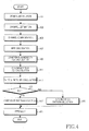
- FIG 4 is a flowchart illustrating an operation for feeding back a pilot pattern in the receiver in the BWA communication system according to the present invention.
- the receiver downconverts an RF signal received through an antenna to a baseband signal and OFDM-demodulates the baseband signal, thus acquiring frequency-domain data in step 401.
- the receiver extracts symbols at subcarrier positions (i.e. pilot symbols) from the frequency-domain data and performs channel estimation using the extracted symbols.
- subcarrier positions i.e. pilot symbols
- the receiver channel-compensates the frequency-domain data using channel estimate values in step 405 and calculates the MSEs of the channel-compensated subcarrier values (complex symbols) in step 407.
- step 409 the receiver accumulates the MSE values along the frequency axis, selects a number of accumulation values in a descending order, and sums them. The sum is the coherence bandwidth C b .
- step 411 the receiver accumulates the MSE values along the time axis, selects a number of accumulation values in a descending order, and sums them. The sum is the coherence time C t .
- the receiver calculates the ratio R of the coherence bandwidth to the coherence time by dividing C b by C t and calculating the Log 10 of the division result in step 413.
- step 415 the receiver compares the ratio R with 1. If R is less than 1, which implies that the coherence bandwidth is greater than the coherence time, the receiver selects a first pilot pattern in which pilot symbols are mapped more densely along the time axis in step 417.
- the receiver selects a second pilot pattern in which pilot symbols are mapped more densely along the frequency axis in step 419.
- the receiver After selecting the pilot pattern, the receiver generates feedback information indicating the selected pilot pattern and sends the feedback information on the feedback channel to the transmitter in step 421.
- FIG. 5 is a graph illustrating a first embodiment of a pilot pattern selection method according to the present invention. A 64x64 frame size and mapping of 64 pilot symbols per frame are assumed.
- a pilot pattern is selected in which the ratio R (C b /C t ) converges to 1. If the coherence bandwidth is greater than the coherence time, the 16x4 first pilot pattern is selected in which pilot symbols are mapped at an interval of 16 along the frequency axis and at an interval of 4 along the time axis. If the coherence time is greater than the coherence bandwidth, the 4x16 second pilot pattern is selected in which pilot symbols are mapped at an interval of 4 along the frequency axis and at an interval of 16 along the time axis. In this manner, although the same number of pilot symbols are allocated to each frame, the layout of the pilot symbols is adapted to the link status.
- FIG. 6 is a graph illustrating a second embodiment of a pilot pattern selection method according to the present invention.
- two thresholds are set for pilot pattern switching. If the ratio R (C b /C t ) is greater than a first threshold, the 16x4 first pilot pattern is selected. If the ratio R is between the first and second thresholds, an 8x8 third pilot pattern is selected in which pilot symbols are mapped at an interval of 8 along the frequency axis and at an interval of 8 along the time axis. If the ratio R is less than the second threshold, the 4x16 second pilot pattern is selected.
- This pilot pattern selection method leads to robust operation against factors such as sudden channel changes or frame delay by use of a smooth transitional pattern.
- the first and second thresholds are empirically obtained.
- Table 1 Carrier frequency 5 GHz FFT size 1024 (16 users) Bandwidth 40MHz Symbol length 25.6 ⁇ s Guard interval 3.2 ⁇ s (T/8) Max delay spread 5ns, 10ns Mobile velocity 5km/h, 160km/h Modulation QPSK Channel estimator Bilinear interpolation Pilot patterns used 3 (4x16, 8x8, 16x4) Pilot density ⁇ 2% User frame size 64x64 Channels AWGN, 3-ray indoor
- FIG. 7 is a graph comparing the present invention using an adaptive pilot pattern with a conventional technology using a fixed pilot pattern in terms of performance.
- the horizontal axis represents received signal strength (E b /N o ) and the vertical axis represents Bit Error Rate (BER).
- the adaptive pilot pattern method of the present invention outperforms the conventional fixed pilot pattern method.
- the present invention advantageously reduces channel estimation errors by adaptively mapping the same number of pilot symbols in a different layout according to the link status.
- the minimization of channel estimation errors leads to the increase of data BER.
- the present invention reduces signaling overhead by switching a pilot pattern on a frame-by-frame basis.
Applications Claiming Priority (1)
| Application Number | Priority Date | Filing Date | Title |
|---|---|---|---|
| KR1020050132859A KR100872043B1 (ko) | 2005-12-29 | 2005-12-29 | 광대역 무선접속 통신시스템에서 파일럿 패턴 결정 장치 및방법 |
Publications (3)
| Publication Number | Publication Date |
|---|---|
| EP1804451A2 true EP1804451A2 (fr) | 2007-07-04 |
| EP1804451A3 EP1804451A3 (fr) | 2012-12-05 |
| EP1804451B1 EP1804451B1 (fr) | 2019-01-02 |
Family
ID=37998360
Family Applications (1)
| Application Number | Title | Priority Date | Filing Date |
|---|---|---|---|
| EP06124823.3A Expired - Fee Related EP1804451B1 (fr) | 2005-12-29 | 2006-11-27 | Appareil et procédé de détermination de trame pilote dans un système de communication par accès sans fil large bande |
Country Status (3)
| Country | Link |
|---|---|
| US (1) | US7792201B2 (fr) |
| EP (1) | EP1804451B1 (fr) |
| KR (1) | KR100872043B1 (fr) |
Cited By (3)
| Publication number | Priority date | Publication date | Assignee | Title |
|---|---|---|---|---|
| WO2009040747A2 (fr) * | 2007-09-28 | 2009-04-02 | Koninklijke Philips Electronics N.V. | Modification d'un motif de symboles pilotes |
| WO2012045448A1 (fr) * | 2010-10-07 | 2012-04-12 | Lantiq Deutschland Gmbh | Placement de pilote dynamique |
| WO2017132806A1 (fr) * | 2016-02-01 | 2017-08-10 | 华为技术有限公司 | Procédé de configuration de signal pilote, et premier dispositif |
Families Citing this family (12)
| Publication number | Priority date | Publication date | Assignee | Title |
|---|---|---|---|---|
| KR100872043B1 (ko) * | 2005-12-29 | 2008-12-05 | 삼성전자주식회사 | 광대역 무선접속 통신시스템에서 파일럿 패턴 결정 장치 및방법 |
| US20080159448A1 (en) * | 2006-12-29 | 2008-07-03 | Texas Instruments, Incorporated | System and method for crosstalk cancellation |
| WO2008129476A2 (fr) * | 2007-04-24 | 2008-10-30 | Koninklijke Philips Electronics N.V. | Réseau à fréquence unique |
| GB2449935A (en) * | 2007-06-08 | 2008-12-10 | Fujitsu Ltd | Closed loop MIMO communication system using SISO r.m.s. delay spread to estimate eigen coherence bandwidth. |
| PL2131540T3 (pl) * | 2008-06-04 | 2013-12-31 | Sony Corp | Nowa struktura ramki dla systemów z wieloma nośnymi |
| US8194529B2 (en) | 2008-09-08 | 2012-06-05 | Sony Corporation | Frame and data pattern structure for multi-carrier systems |
| AU2009217407C1 (en) | 2008-10-09 | 2015-07-23 | Sony Corporation | New frame and data pattern structure for multi-carrier systems |
| KR101083081B1 (ko) | 2008-12-15 | 2011-11-16 | 한국전자통신연구원 | 직교주파수분할 시스템에서 채널 추정을 위한 패턴 삽입시 전송시간 계산방법 및 그 장치 |
| US8275319B2 (en) * | 2009-03-11 | 2012-09-25 | Broadcom Corporation | Processing of multi-carrier signals before power amplifier amplification |
| WO2013058599A1 (fr) * | 2011-10-19 | 2013-04-25 | 엘지전자 주식회사 | Procédé et appareil d'émission/réception d'informations de commande de liaison descendante dans un système d'accès sans fil |
| US9893772B2 (en) * | 2012-12-04 | 2018-02-13 | Lg Elctronics Inc. | Method for changing pattern of reference signals according to coherence time variation in wireless communication system and apparatus therefor |
| US10708796B2 (en) * | 2016-04-21 | 2020-07-07 | Qualcomm Incorporated | High doppler channel performance enhancement |
Citations (2)
| Publication number | Priority date | Publication date | Assignee | Title |
|---|---|---|---|---|
| US20040257979A1 (en) * | 2003-06-18 | 2004-12-23 | Samsung Electronics Co., Ltd. | Apparatus and method for tranmitting and receiving a pilot pattern for identification of a base station in an OFDM communication system |
| WO2005015797A1 (fr) * | 2003-08-12 | 2005-02-17 | Matsushita Electric Industrial Co., Ltd. | Dispositif de radiocommunication et procede de transmission de symboles pilotes |
Family Cites Families (43)
| Publication number | Priority date | Publication date | Assignee | Title |
|---|---|---|---|---|
| US5589763A (en) * | 1995-05-16 | 1996-12-31 | Texas Instruments Incorporated | Coherent undersampling digitizer for use with automatic field test equipment |
| DE69838807T2 (de) * | 1998-02-18 | 2008-10-30 | Sony Deutschland Gmbh | Abbildung von Mehrträgersignalen in GSM-Zeitschlitzen |
| WO2000065756A1 (fr) * | 1999-04-22 | 2000-11-02 | Nippon Telegraph And Telephone Corporation | Recepteur de communication par paquets ofdm |
| US6385264B1 (en) * | 1999-06-08 | 2002-05-07 | Qualcomm Incorporated | Method and apparatus for mitigating interference between base stations in a wideband CDMA system |
| KR100526499B1 (ko) * | 2000-08-22 | 2005-11-08 | 삼성전자주식회사 | 두 개 이상 안테나를 사용하는 안테나 전송 다이버시티방법 및 장치 |
| US6725058B2 (en) * | 2001-12-26 | 2004-04-20 | Nokia Corporation | Intersystem handover |
| KR100790114B1 (ko) * | 2002-03-16 | 2007-12-31 | 삼성전자주식회사 | 직교주파수 분할다중 접속 시스템에서 적응적 파일럿반송파 할당 방법 및 장치 |
| JP2004135120A (ja) * | 2002-10-11 | 2004-04-30 | Matsushita Electric Ind Co Ltd | ダイバーシティ受信装置及びダイバーシティ受信方法 |
| AU2002952566A0 (en) * | 2002-11-07 | 2002-11-21 | Dspace Pty Ltd | Pilot symbol patterns in communication systems |
| KR100507519B1 (ko) * | 2002-12-13 | 2005-08-17 | 한국전자통신연구원 | Ofdma 기반 셀룰러 시스템의 하향링크를 위한 신호구성 방법 및 장치 |
| US7280467B2 (en) * | 2003-01-07 | 2007-10-09 | Qualcomm Incorporated | Pilot transmission schemes for wireless multi-carrier communication systems |
| US20060172716A1 (en) * | 2003-03-14 | 2006-08-03 | Matsushita Electric Industrail Co., Ltd. | Ofdm reception device and ofdm reception method |
| EP1635494B1 (fr) * | 2003-06-19 | 2010-04-21 | Sony Corporation | Système de communication radio, dispositif de réception et procédé de réception pour transmission multi-porteuse |
| CN1802832B (zh) * | 2003-06-30 | 2010-12-01 | 诺基亚公司 | 多载波系统中的更快速的精确定时操作 |
| KR100606105B1 (ko) * | 2003-07-04 | 2006-07-28 | 삼성전자주식회사 | 다중 접속 방식을 사용하는 이동 통신 시스템의 셀 탐색장치 및 방법 |
| KR100918730B1 (ko) * | 2003-10-27 | 2009-09-24 | 삼성전자주식회사 | 직교 주파수 분할 다중 방식을 사용하는 통신 시스템에서기지국 구분을 위한 파일럿 패턴 세트 송수신 장치 및 방법 |
| KR100969780B1 (ko) * | 2003-10-31 | 2010-07-13 | 삼성전자주식회사 | 직교 주파수 분할 다중 방식 통신 시스템에서 파일럿 신호 송수신 장치 및 방법 |
| KR100856227B1 (ko) * | 2003-12-15 | 2008-09-03 | 삼성전자주식회사 | 이동통신시스템에서의 송/수신장치 및 방법 |
| KR100507541B1 (ko) * | 2003-12-19 | 2005-08-09 | 삼성전자주식회사 | 직교주파수분할다중접속 시스템에서의 데이터 및 파일롯할당 방법 과 그를 이용한 송신 방법 및 그 장치, 수신방법과 그 장치 |
| KR100564601B1 (ko) * | 2003-12-29 | 2006-03-28 | 삼성전자주식회사 | 주파수 도메인 에코 검출방법 및 이를 사용하는 이퀄라이저 |
| CN1939026B (zh) * | 2004-01-28 | 2012-07-04 | 高通股份有限公司 | Ofdm接收机中的定时估计 |
| EP1583306B1 (fr) * | 2004-03-10 | 2014-05-07 | St Microelectronics S.A. | Démodulateur COFDM |
| US7426175B2 (en) * | 2004-03-30 | 2008-09-16 | Motorola, Inc. | Method and apparatus for pilot signal transmission |
| KR100643740B1 (ko) * | 2004-04-09 | 2006-11-10 | 삼성전자주식회사 | 직교 주파수 분할 다중 방식을 사용하는 통신 시스템에서기지국 구분을 위한 파일럿 코드 패턴 송수신 장치 및 방법 |
| KR100651556B1 (ko) * | 2004-06-30 | 2006-11-29 | 삼성전자주식회사 | 통신 시스템에서 cinr 추정 장치 및 방법 |
| BRPI0515280A (pt) * | 2004-09-18 | 2008-07-15 | Samsung Electronics Co Ltd | aparelho e método para sincronização de freqüência em um sistema ofdm |
| KR100663571B1 (ko) * | 2004-09-20 | 2007-01-02 | 삼성전자주식회사 | 주파수도약 직교주파수분할다중화 기반의 다중입출력 통신시스템을 위한 기지국 식별 방법 |
| US20060078059A1 (en) * | 2004-10-11 | 2006-04-13 | Samsung Electronics Co., Ltd. | Apparatus and method for allocating subchannel and power in an orthogonal frequency division multiple access system |
| US7239659B2 (en) * | 2004-11-04 | 2007-07-03 | Motorola, Inc. | Method and apparatus for channel feedback |
| KR100981514B1 (ko) * | 2004-12-30 | 2010-09-10 | 삼성전자주식회사 | 직교 주파수 분할 다중 접속 통신 시스템에서 부분 채널 정보 피드백을 이용한 적응 부채널 및 비트 할당 방법 |
| KR100594086B1 (ko) * | 2005-01-04 | 2006-06-30 | 삼성전자주식회사 | 채널 추정을 위한 적응적 파일럿 할당 방법 및 장치 |
| EP1699198A1 (fr) * | 2005-03-01 | 2006-09-06 | Alcatel | Distribution des données sur une grille de temps-fréquence d'OFDM en rassemblant des sous-porteuses en modèles de fréquence diverse et de fréquence sélective |
| US8009775B2 (en) * | 2005-03-11 | 2011-08-30 | Qualcomm Incorporated | Automatic frequency control for a wireless communication system with multiple subcarriers |
| KR100880991B1 (ko) * | 2005-06-16 | 2009-02-03 | 삼성전자주식회사 | 이동통신 시스템에서 다중 안테나를 이용한 파일럿 송수신장치 및 방법 |
| US7471241B1 (en) * | 2005-07-25 | 2008-12-30 | Chun Yang | Global navigation satellite system (GNSS) receivers based on satellite signal channel impulse response |
| US8885628B2 (en) * | 2005-08-08 | 2014-11-11 | Qualcomm Incorporated | Code division multiplexing in a single-carrier frequency division multiple access system |
| TR201904500T4 (tr) * | 2005-09-27 | 2019-05-21 | Nokia Technologies Oy | Çok taşıyıcılı iletimler için pilot yapısı. |
| US7450559B2 (en) * | 2005-10-13 | 2008-11-11 | Qualcomm Incorporated | Method and apparatus for preserving compatibility between legacy mode(s) of operation and new mode(s) of operation in a communication system |
| KR100691430B1 (ko) * | 2005-12-05 | 2007-03-09 | 한국전자통신연구원 | 이동통신 시스템에서 제한된 궤환 정보를 이용한 적응 송신방법 및 장치 |
| KR100872043B1 (ko) * | 2005-12-29 | 2008-12-05 | 삼성전자주식회사 | 광대역 무선접속 통신시스템에서 파일럿 패턴 결정 장치 및방법 |
| JPWO2007125910A1 (ja) * | 2006-04-25 | 2009-09-10 | パナソニック株式会社 | 無線通信端末装置、無線通信基地局装置及び無線通信方法 |
| KR101314926B1 (ko) * | 2006-12-07 | 2013-10-04 | 인터디지탈 테크날러지 코포레이션 | 트레이닝 신호와 정보 비트들을 할당하기 위한 무선 통신 방법 및 장치 |
| US8315660B2 (en) * | 2007-02-14 | 2012-11-20 | Qualcomm Incorporated | User power offset estimation using dedicated pilot tones for OFDMA |
-
2005
- 2005-12-29 KR KR1020050132859A patent/KR100872043B1/ko active IP Right Grant
-
2006
- 2006-11-27 EP EP06124823.3A patent/EP1804451B1/fr not_active Expired - Fee Related
- 2006-12-29 US US11/647,949 patent/US7792201B2/en not_active Expired - Fee Related
Patent Citations (2)
| Publication number | Priority date | Publication date | Assignee | Title |
|---|---|---|---|---|
| US20040257979A1 (en) * | 2003-06-18 | 2004-12-23 | Samsung Electronics Co., Ltd. | Apparatus and method for tranmitting and receiving a pilot pattern for identification of a base station in an OFDM communication system |
| WO2005015797A1 (fr) * | 2003-08-12 | 2005-02-17 | Matsushita Electric Industrial Co., Ltd. | Dispositif de radiocommunication et procede de transmission de symboles pilotes |
Cited By (4)
| Publication number | Priority date | Publication date | Assignee | Title |
|---|---|---|---|---|
| WO2009040747A2 (fr) * | 2007-09-28 | 2009-04-02 | Koninklijke Philips Electronics N.V. | Modification d'un motif de symboles pilotes |
| WO2009040747A3 (fr) * | 2007-09-28 | 2009-05-22 | Koninkl Philips Electronics Nv | Modification d'un motif de symboles pilotes |
| WO2012045448A1 (fr) * | 2010-10-07 | 2012-04-12 | Lantiq Deutschland Gmbh | Placement de pilote dynamique |
| WO2017132806A1 (fr) * | 2016-02-01 | 2017-08-10 | 华为技术有限公司 | Procédé de configuration de signal pilote, et premier dispositif |
Also Published As
| Publication number | Publication date |
|---|---|
| KR100872043B1 (ko) | 2008-12-05 |
| EP1804451B1 (fr) | 2019-01-02 |
| KR20070070375A (ko) | 2007-07-04 |
| US7792201B2 (en) | 2010-09-07 |
| EP1804451A3 (fr) | 2012-12-05 |
| US20070153931A1 (en) | 2007-07-05 |
Similar Documents
| Publication | Publication Date | Title |
|---|---|---|
| EP1804451B1 (fr) | Appareil et procédé de détermination de trame pilote dans un système de communication par accès sans fil large bande | |
| US9572172B2 (en) | Adaptive scheduling of voice traffic in a multi-carrier communication environment | |
| US7492701B2 (en) | Apparatus and method for controlling adaptive modulation and coding in an orthogonal frequency division multiplexing communication system | |
| US8571132B2 (en) | Constrained hopping in wireless communication systems | |
| EP2256985B1 (fr) | Pilotes configurables dans un système de communication sans fil | |
| EP2936755B1 (fr) | Procédé et appareil de transmission/réception d'un signal dans un système de communication | |
| EP2938035B1 (fr) | Procédé et dispositif pour émettre et recevoir un signal à l'aide de techniques de modulation dans un système de communication sans fil | |
| JP4284280B2 (ja) | 無線通信システムおよび無線送信装置 | |
| EP1811734B1 (fr) | Procédé et appareil de commande des transmissions et réceptions des pilotes dédiés selon le niveau MCS dans un système de communication sans fil | |
| KR101333934B1 (ko) | 무선 통신 시스템 | |
| EP1806893A2 (fr) | Appareil et procédé pour communiquer des données en mode de diversité hybride dans un système de communication sans fil à bande large | |
| JPWO2005006622A1 (ja) | マルチキャリア送信装置、マルチキャリア受信装置及びマルチキャリア通信方法 | |
| KR20070045343A (ko) | 송신 장치, 수신 장치, 통신 시스템 및 통신 방법 | |
| JP4748678B2 (ja) | パイロット信号配置を適応的に変更する無線装置、プログラム及び通信方法 | |
| KR20070015996A (ko) | 광대역 무선 접속 통신 시스템에서 채널 품질 정보 수신장치 및 방법 | |
| JP2002016577A (ja) | 通信方法および通信装置 | |
| US8750433B2 (en) | Demodulation circuit, demodulation method and receiving apparatus | |
| US8750397B2 (en) | Apparatus and method for channel estimation in wireless communication system | |
| KR20080040112A (ko) | 채널 에러 보상 방법 및 변조 및 코딩 방식 결정 방법 | |
| KR20050119592A (ko) | 주파수 도약-직교 주파수 분할 다중 접속 방식을 사용하는이동 통신 시스템에서 채널 추정 장치 및 방법 | |
| KR20070096443A (ko) | 통신 시스템에서 신호 송수신 장치 및 방법 |
Legal Events
| Date | Code | Title | Description |
|---|---|---|---|
| PUAI | Public reference made under article 153(3) epc to a published international application that has entered the european phase |
Free format text: ORIGINAL CODE: 0009012 |
|
| 17P | Request for examination filed |
Effective date: 20061127 |
|
| AK | Designated contracting states |
Kind code of ref document: A2 Designated state(s): AT BE BG CH CY CZ DE DK EE ES FI FR GB GR HU IE IS IT LI LT LU LV MC NL PL PT RO SE SI SK TR |
|
| AX | Request for extension of the european patent |
Extension state: AL BA HR MK YU |
|
| RAP1 | Party data changed (applicant data changed or rights of an application transferred) |
Owner name: INDUSTRY-ACADEMIC COOPERATION FOUNDATION, YONSEI U Owner name: SAMSUNG ELECTRONICS CO., LTD. |
|
| PUAL | Search report despatched |
Free format text: ORIGINAL CODE: 0009013 |
|
| AK | Designated contracting states |
Kind code of ref document: A3 Designated state(s): AT BE BG CH CY CZ DE DK EE ES FI FR GB GR HU IE IS IT LI LT LU LV MC NL PL PT RO SE SI SK TR |
|
| AX | Request for extension of the european patent |
Extension state: AL BA HR MK RS |
|
| RIC1 | Information provided on ipc code assigned before grant |
Ipc: H04L 1/00 20060101ALI20121026BHEP Ipc: H04L 25/02 20060101ALI20121026BHEP Ipc: H04L 27/26 20060101AFI20121026BHEP |
|
| AKX | Designation fees paid |
Designated state(s): DE FR GB IT SE |
|
| 17Q | First examination report despatched |
Effective date: 20171011 |
|
| GRAP | Despatch of communication of intention to grant a patent |
Free format text: ORIGINAL CODE: EPIDOSNIGR1 |
|
| INTG | Intention to grant announced |
Effective date: 20180719 |
|
| GRAS | Grant fee paid |
Free format text: ORIGINAL CODE: EPIDOSNIGR3 |
|
| GRAA | (expected) grant |
Free format text: ORIGINAL CODE: 0009210 |
|
| AK | Designated contracting states |
Kind code of ref document: B1 Designated state(s): DE FR GB IT SE |
|
| REG | Reference to a national code |
Ref country code: GB Ref legal event code: FG4D |
|
| REG | Reference to a national code |
Ref country code: DE Ref legal event code: R096 Ref document number: 602006057188 Country of ref document: DE |
|
| PG25 | Lapsed in a contracting state [announced via postgrant information from national office to epo] |
Ref country code: SE Free format text: LAPSE BECAUSE OF FAILURE TO SUBMIT A TRANSLATION OF THE DESCRIPTION OR TO PAY THE FEE WITHIN THE PRESCRIBED TIME-LIMIT Effective date: 20190102 |
|
| REG | Reference to a national code |
Ref country code: DE Ref legal event code: R097 Ref document number: 602006057188 Country of ref document: DE |
|
| PG25 | Lapsed in a contracting state [announced via postgrant information from national office to epo] |
Ref country code: IT Free format text: LAPSE BECAUSE OF FAILURE TO SUBMIT A TRANSLATION OF THE DESCRIPTION OR TO PAY THE FEE WITHIN THE PRESCRIBED TIME-LIMIT Effective date: 20190102 |
|
| PLBE | No opposition filed within time limit |
Free format text: ORIGINAL CODE: 0009261 |
|
| STAA | Information on the status of an ep patent application or granted ep patent |
Free format text: STATUS: NO OPPOSITION FILED WITHIN TIME LIMIT |
|
| 26N | No opposition filed |
Effective date: 20191003 |
|
| REG | Reference to a national code |
Ref country code: DE Ref legal event code: R119 Ref document number: 602006057188 Country of ref document: DE |
|
| GBPC | Gb: european patent ceased through non-payment of renewal fee |
Effective date: 20191127 |
|
| PG25 | Lapsed in a contracting state [announced via postgrant information from national office to epo] |
Ref country code: GB Free format text: LAPSE BECAUSE OF NON-PAYMENT OF DUE FEES Effective date: 20191127 Ref country code: DE Free format text: LAPSE BECAUSE OF NON-PAYMENT OF DUE FEES Effective date: 20200603 Ref country code: FR Free format text: LAPSE BECAUSE OF NON-PAYMENT OF DUE FEES Effective date: 20191130 |