EP1803964A2 - Module hybride de rigidité pour isolation de vibrations - Google Patents
Module hybride de rigidité pour isolation de vibrations Download PDFInfo
- Publication number
- EP1803964A2 EP1803964A2 EP06009025A EP06009025A EP1803964A2 EP 1803964 A2 EP1803964 A2 EP 1803964A2 EP 06009025 A EP06009025 A EP 06009025A EP 06009025 A EP06009025 A EP 06009025A EP 1803964 A2 EP1803964 A2 EP 1803964A2
- Authority
- EP
- European Patent Office
- Prior art keywords
- bearing
- vibration isolation
- horizontal
- spring
- stiffness
- Prior art date
- Legal status (The legal status is an assumption and is not a legal conclusion. Google has not performed a legal analysis and makes no representation as to the accuracy of the status listed.)
- Granted
Links
Images


Classifications
-
- G—PHYSICS
- G03—PHOTOGRAPHY; CINEMATOGRAPHY; ANALOGOUS TECHNIQUES USING WAVES OTHER THAN OPTICAL WAVES; ELECTROGRAPHY; HOLOGRAPHY
- G03F—PHOTOMECHANICAL PRODUCTION OF TEXTURED OR PATTERNED SURFACES, e.g. FOR PRINTING, FOR PROCESSING OF SEMICONDUCTOR DEVICES; MATERIALS THEREFOR; ORIGINALS THEREFOR; APPARATUS SPECIALLY ADAPTED THEREFOR
- G03F7/00—Photomechanical, e.g. photolithographic, production of textured or patterned surfaces, e.g. printing surfaces; Materials therefor, e.g. comprising photoresists; Apparatus specially adapted therefor
- G03F7/70—Microphotolithographic exposure; Apparatus therefor
- G03F7/708—Construction of apparatus, e.g. environment aspects, hygiene aspects or materials
- G03F7/70858—Environment aspects, e.g. pressure of beam-path gas, temperature
- G03F7/709—Vibration, e.g. vibration detection, compensation, suppression or isolation
-
- F—MECHANICAL ENGINEERING; LIGHTING; HEATING; WEAPONS; BLASTING
- F16—ENGINEERING ELEMENTS AND UNITS; GENERAL MEASURES FOR PRODUCING AND MAINTAINING EFFECTIVE FUNCTIONING OF MACHINES OR INSTALLATIONS; THERMAL INSULATION IN GENERAL
- F16F—SPRINGS; SHOCK-ABSORBERS; MEANS FOR DAMPING VIBRATION
- F16F15/00—Suppression of vibrations in systems; Means or arrangements for avoiding or reducing out-of-balance forces, e.g. due to motion
- F16F15/02—Suppression of vibrations of non-rotating, e.g. reciprocating systems; Suppression of vibrations of rotating systems by use of members not moving with the rotating systems
- F16F15/023—Suppression of vibrations of non-rotating, e.g. reciprocating systems; Suppression of vibrations of rotating systems by use of members not moving with the rotating systems using fluid means
- F16F15/027—Suppression of vibrations of non-rotating, e.g. reciprocating systems; Suppression of vibrations of rotating systems by use of members not moving with the rotating systems using fluid means comprising control arrangements
- F16F15/0275—Control of stiffness
-
- F—MECHANICAL ENGINEERING; LIGHTING; HEATING; WEAPONS; BLASTING
- F16—ENGINEERING ELEMENTS AND UNITS; GENERAL MEASURES FOR PRODUCING AND MAINTAINING EFFECTIVE FUNCTIONING OF MACHINES OR INSTALLATIONS; THERMAL INSULATION IN GENERAL
- F16F—SPRINGS; SHOCK-ABSORBERS; MEANS FOR DAMPING VIBRATION
- F16F2230/00—Purpose; Design features
- F16F2230/34—Flexural hinges
Definitions
- the invention relates to a bearing for vibration isolation, as well as a vibration isolation system and a method for vibration isolation, in which at least one fluid bearing is part of a bearing for vibration isolation.
- Vibration isolation systems are known.
- FIG. 1 shows the EP 927 380 B1 a vertically and horizontally effective air bearing, with which in particular a vibration isolation system can be provided for storage of a lithography device.
- This horizontally and vertically effective air bearing is an open system, which means that compressed air continuously flows through the bearing, so that the load to be stored is decoupled from the base without contact.
- Such air bearings have the disadvantage of high air consumption and are sensitive to fluctuations in the supply air pressure.
- such bearings are subject to a noise, which leads to an isolation against small low-frequency Vibration amplitudes is only possible to a limited extent.
- such bearings by design have a much higher rigidity in the horizontal direction. Such a bearing is therefore not particularly well suited for the isolation of vibrations which have a horizontal component.
- vibration isolation systems In the semiconductor industry, with the miniaturization of components, more and more demands are placed on such vibration isolation systems. Due to arranged on the vibration isolation system movable machine elements, such as robots for the production of semiconductor devices, vibrations occur increasingly, which have high horizontal force components.
- air bearings are known from practice, which are closed, for example designed as bellows filled with compressed air. Such bearings are not suitable for low-frequency vibration amplitudes due to the resulting mechanical connection of base and load to be stored.
- the invention is based on the object to provide a bearing for vibration isolation and a method for vibration isolation, which reduces the above-mentioned disadvantages of the prior art.
- object of the invention to provide a bearing for vibration isolation, which is the horizontal stiffness of the bearing, in particular in Low-frequency range and thus also allows effective isolation against low-frequency oscillations with a small amplitude of vibration.
- a further object of the invention is to provide an air bearing which, with equally good or even improved insulation effect, requires less air consumption.
- the object of the invention is already achieved by a bearing for vibration isolation, a vibration isolation system and a method for vibration isolation according to one of the independent claims.
- the invention provides a bearing for vibration isolation, which comprises at least one fluid bearing, in particular designed as an air bearing.
- the air bearing is preferably designed for both horizontal and vertical mounting of a load to be insulated, so it is effective both in the horizontal and in the vertical direction.
- the bearing for vibration isolation comprises at least two vertically spaced, in particular mechanically operating, pivot joints.
- these hinges which preferably have a spring stiffness, so are designed as a spring rotating joint, is added to the air bearing added Isolation achieved in the horizontal direction.
- the two hinges are preferably movable like a ball joint, so that the load to be isolated can move in the horizontal direction with simultaneous movement of the joints at the same angle.
- the horizontal insulation can be essentially taken over by the two hinges.
- the fluid bearing has, as in a preferred embodiment of the invention, a horizontal rigidity which is more than 5, preferably more than 10, and more preferably more than 15 times as large as the vertical rigidity. So fluid bearings can be installed with a low horizontal stiffness. The thickness of the air gaps can thus be reduced, whereby the air consumption of a vibration isolation system provided with corresponding bearings for vibration isolation can be reduced.
- the vertical rigidity of the bearing is at least 0.5, preferably 0.7 and more preferably 0.9 times the horizontal stiffness of the bearing.
- a bearing can be provided in which the horizontal rigidity is similarly low or even lower as the vertical rigidity. An isolation against vibrations with horizontal force component is therefore possible without significant restrictions.
- the hinges are in a preferred embodiment of the invention at least in the two Rotational degrees of freedom, which are substantially perpendicular to a vertical axis, movable. This improves the horizontal rigidity of the bearing in all directions of the horizontal plane.
- the pivots are arranged above and below the fluid bearing, or it is located the pivot point substantially above and below the fluid bearing.
- At least one of the swivel joints is designed as a bellows, in particular as a metal bellows.
- a bellows contribute in addition to a property as a hinge at the same time to the isolation and at the same time have a spring stiffness, so that can be dispensed with further spring components for aligning the bearing.
- a lower hinge is designed as a bellows
- the fluid supply can take place via this bellows, so that the bellows is also part of the fluid supply.
- metal bellows are used which are less prone to be excited by passing air to resonant vibrations. The existing power noise in the system is reduced.
- the bearing has a further spring, in particular a leaf spring.
- This leaf spring is preferably formed so that the stiffness perpendicular to the axis of the bearing, ie in the horizontal direction is higher than the vertical stiffness.
- the leaf spring has a horizontal rigidity which is at least five times higher than the vertical rigidity.
- the hinge can be designed as a spring joint.
- the low vertical stiffness of the spring minimizes coupling of vibrations by the spring into the vibration isolation system.
- the horizontal stiffness of the further spring is variable and can be adjusted, for example mechanically or via an electric or pneumatic actuator.
- a bearing can be provided which has a variable adjustable horizontal stiffness. It is particularly advantageous that the horizontal stiffness does not have to be adjusted via the fluid pressure. An increased horizontal rigidity therefore does not result increased air consumption.
- horizontal and vertical rigidity do not substantially depend on each other.
- a vertical spring of the fluid bearing is sealed, in particular by means of an elastomeric skin or a rubber membrane. It is particularly intended to design such a spring as an air spring. Due to the seal, this is a closed system, which reduces the air consumption of the fluid bearing.
- At least one rotary joint in particular the lower rotary joint, is designed as an articulated joint.
- Such buckling pendulum which are loaded on bending, also allow the design as a torsion spring bearing.
- At least one actuator in particular a piezoelectric actuator or a magnetic actuator is provided in the bearing, which allows active control of the bearing in at least one degree of freedom.
- Such an actuator preferably acts without contact on the load to be stored and it can be actively eliminated with the actuator vibrations.
- the actuator control can also be used to change the characteristic of the bearing, for example in load changes of the vibration isolation system.
- the bearing comprises at least one sensor for measuring changes in position between the load, base and / or part of the bearing to be insulated.
- a sensor for measuring changes in position between the load, base and / or part of the bearing to be insulated.
- about such a sensor are preferably non-contact Changes in position, in particular recorded vibrations of the load to be isolated.
- these changes in position via actuators or via the regulation of the fluid pressure can be counteracted.
- the invention further relates to a vibration isolation system comprising at least one vibration isolation bearing according to the invention.
- the vibration isolation system further comprises a sensor for detecting changes in position of the load to be isolated in at least one spatial direction.
- This sensor can be arranged both at the warehouse and at any point of the load to be isolated.
- the vibration isolation system has a control device which generates compensation signals via an active control and thus controls actuators or the fluid bearing.
- the invention relates to a method for vibration isolation, in which in particular a bearing according to the invention is used for vibration isolation.
- a load to be isolated is isolated against vibrations via at least one fluid bearing.
- a load to be isolated is isolated against vibrations via at least one fluid bearing.
- the lowering of the load to be insulated which is inevitably caused by a movement of the swivel joints as a result of a horizontal displacement of the load to be insulated, automatically compensated by an active control.
- This automatic compensation can be done in particular via the fluid pressure or the actuators.
- a bearing is provided in which the horizontal insulation is at least 60%, preferably 70% and particularly preferably 85% via the hinges.
- the vibration isolation bearing 1 comprises as fluid bearing an air bearing 2, which comprises a piston 3, which runs in a cylinder 4.
- the air bearing 2 is configured as an open air bearing: In the operating state, an air gap 5 forms between the piston 3 and the cylinder 4, as a result of which the piston 3 runs without contact in the cylinder 4.
- Such an air bearing 2 has a relatively low stiffness in the vertical direction, ie along the indicated Z-axis.
- this embodiment is a purely mechanical joint, while the lower swivel joint 8 is configured as bellows and via which the air bearing 2 is simultaneously supplied with compressed air.
- Upper pivot 6 and lower pivot 8 are vertical, ie spaced apart in the direction of the Z-axis, to perform a geometrically opposite but simultaneous rotation. Since the hinges 6, 8 are arranged above and below the air bearing 2, the air bearing 2 acts as a lever between the two pivot points whose distance is indicated by a). Thus, the height of the bearing for vibration isolation 1 is not significantly higher than a pure air bearing.
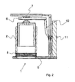
- FIG. 2 a further embodiment of the invention will be explained in more detail.
- the bearing for vibration isolation 1 according to FIG. 2 essentially corresponds to FIG. 1.
- a load 7 to be insulated is mounted on an air bearing 2.
- the vibration isolation bearing 1 in this embodiment has a leaf spring 10 which has high rigidity in the horizontal direction but low rigidity in the vertical direction. Via an actuator 11, at least the horizontal stiffness of the leaf spring 10 can be adjusted. This is accompanied by a change in the horizontal rigidity of the entire warehouse.
- the bearing for vibration isolation 1 can be adapted to different operating conditions. It is also conceivable, the actuator 11 via a control device (not shown) to control and so adjust the bearing for vibration isolation 1 automatically changed operating conditions.
- the lower hinge 8 is designed as a torsion spring joint using three articulated bumps 12.
- the articulated pendulum 12 are connected to the fluid bearing via horizontal cross member 13 and are based on the base 9 from.
- the upper pivot 6 is not configured as a torsion spring bearing, but as a purely mechanical bearing.
- FIG. 1 Another embodiment of the invention is shown in FIG. 1
- the buckling pendulum 12 are designed as solid-state joints, which have recesses 14 to achieve a lower rigidity. These too Solid joints designed buckling pendulum 12 are connected via a cross member with the fluid bearing 2.
- Fig. 5 shows a schematic perspective view of a rubber buffer 15, as it may be part of a torsion spring joint.
- the rubber buffer 15 is designed essentially of solid material and has recesses 16 in order to be able to be held on both sides in a receptacle (not shown).
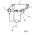
- the vibration isolation system 20 has a load 7 to be insulated, which is shown as a plate and which is designed to accommodate further components (not shown), which also belong to the insulating load.
- the 7 load to be insulated is mounted on four bearings for vibration isolation 1. Via a sensor 21 changes in position of the load to be isolated 7 are detected without contact and regulated the corresponding signal to a control device 23 on. Both the air pressure of the bearing 1 is controlled via the control device 23, in particular in order to provide a constant level of the load 7 to be insulated. At the same time, the control device 23 controls an actuator 22, which acts contactlessly on the load 7 to be insulated and with which, in particular, higher-frequency vibrations in all three spatial directions can be counteracted.
Landscapes
- Engineering & Computer Science (AREA)
- Physics & Mathematics (AREA)
- Health & Medical Sciences (AREA)
- General Engineering & Computer Science (AREA)
- General Physics & Mathematics (AREA)
- Environmental & Geological Engineering (AREA)
- Epidemiology (AREA)
- Atmospheric Sciences (AREA)
- Life Sciences & Earth Sciences (AREA)
- Public Health (AREA)
- Acoustics & Sound (AREA)
- Aviation & Aerospace Engineering (AREA)
- Toxicology (AREA)
- Mechanical Engineering (AREA)
- Vibration Prevention Devices (AREA)
- Buildings Adapted To Withstand Abnormal External Influences (AREA)
Priority Applications (1)
| Application Number | Priority Date | Filing Date | Title |
|---|---|---|---|
| EP06009025.5A EP1803964B1 (fr) | 2005-12-30 | 2006-05-02 | Module hybride de rigidité pour isolation de vibrations |
Applications Claiming Priority (2)
| Application Number | Priority Date | Filing Date | Title |
|---|---|---|---|
| EP20050028716 EP1803963B1 (fr) | 2005-12-30 | 2005-12-30 | Modul hybride de rigidité pour islolation de vibrations |
| EP06009025.5A EP1803964B1 (fr) | 2005-12-30 | 2006-05-02 | Module hybride de rigidité pour isolation de vibrations |
Publications (3)
| Publication Number | Publication Date |
|---|---|
| EP1803964A2 true EP1803964A2 (fr) | 2007-07-04 |
| EP1803964A3 EP1803964A3 (fr) | 2008-12-17 |
| EP1803964B1 EP1803964B1 (fr) | 2016-04-20 |
Family
ID=36353435
Family Applications (2)
| Application Number | Title | Priority Date | Filing Date |
|---|---|---|---|
| EP20050028716 Active EP1803963B1 (fr) | 2005-12-30 | 2005-12-30 | Modul hybride de rigidité pour islolation de vibrations |
| EP06009025.5A Active EP1803964B1 (fr) | 2005-12-30 | 2006-05-02 | Module hybride de rigidité pour isolation de vibrations |
Family Applications Before (1)
| Application Number | Title | Priority Date | Filing Date |
|---|---|---|---|
| EP20050028716 Active EP1803963B1 (fr) | 2005-12-30 | 2005-12-30 | Modul hybride de rigidité pour islolation de vibrations |
Country Status (2)
| Country | Link |
|---|---|
| EP (2) | EP1803963B1 (fr) |
| DE (1) | DE502005008008D1 (fr) |
Cited By (3)
| Publication number | Priority date | Publication date | Assignee | Title |
|---|---|---|---|---|
| WO2016156016A1 (fr) * | 2015-04-02 | 2016-10-06 | Lisega SE | Amortisseur axial |
| EP3771846A1 (fr) * | 2019-07-29 | 2021-02-03 | Siemens Aktiengesellschaft | Système de couplage mécanique destiné au couplage isolant contre les vibrations de deux systèmes partiels |
| US10941833B2 (en) | 2015-12-16 | 2021-03-09 | Integrated Dynamics Engineering Gmbh | Vibration isolator with a vertically effective pneumatic spring |
Families Citing this family (10)
| Publication number | Priority date | Publication date | Assignee | Title |
|---|---|---|---|---|
| EP1803965B1 (fr) * | 2005-12-30 | 2015-03-18 | Integrated Dynamics Engineering GmbH | Géométrie isolatrice d'un système d'isolation vibratoire |
| DE502005008008D1 (de) * | 2005-12-30 | 2009-10-08 | Integrated Dynamics Eng Gmbh | Hybrides Steifigkeitsmodul zur Schwingungsisolation |
| DE102007059631B4 (de) | 2007-12-10 | 2009-09-17 | Integrated Dynamics Engineering Gmbh | Schwingungsisolator zur Verwendung im Vakuum |
| CN102486215B (zh) * | 2010-12-02 | 2014-02-19 | 上海微电子装备有限公司 | 一种重力补偿装置 |
| EP2772661B1 (fr) | 2013-02-28 | 2020-04-01 | Integrated Dynamics Engineering GmbH | Procédé de dimensionnement d'un isolateur de vibrations |
| CN104698766B (zh) * | 2013-12-10 | 2017-01-18 | 上海微电子装备有限公司 | 重力补偿装置 |
| CN108006080A (zh) * | 2017-11-10 | 2018-05-08 | 淮北智淮科技有限公司 | 一种具有减震功能的轴承底座 |
| EP4180247A1 (fr) * | 2021-11-16 | 2023-05-17 | Nio Technology (Anhui) Co., Ltd | Ressort pneumatique - amortisseur pour suspension active de véhicule |
| CN114294371B (zh) * | 2022-01-08 | 2023-03-17 | 厦门大学 | 一种六自由度的空气弹簧隔振平台 |
| CN114458723B (zh) * | 2022-02-14 | 2023-07-21 | 国网重庆市电力公司电力科学研究院 | 一种准零刚度隔振装置及其设计方法 |
Citations (1)
| Publication number | Priority date | Publication date | Assignee | Title |
|---|---|---|---|---|
| EP0927380B1 (fr) | 1997-07-22 | 2003-09-03 | ASML Netherlands B.V. | Dispositif de support dote d'un ressort a gaz |
Family Cites Families (11)
| Publication number | Priority date | Publication date | Assignee | Title |
|---|---|---|---|---|
| BE476448A (fr) * | ||||
| AU4399496A (en) * | 1994-12-22 | 1996-07-10 | Oseney Limited | An end mounting for a ram housing |
| DE19606994A1 (de) * | 1996-02-24 | 1997-07-03 | Daimler Benz Ag | Feder-Stoßdämpfer-Einrichtung eines Kraftfahrzeuges |
| EP0973067A3 (fr) * | 1998-07-17 | 2001-10-24 | ASM Lithography B.V. | Dispositif de positionnement et appareil de projection lithographique muni d'un tel dispositif |
| US6408767B1 (en) * | 2000-03-01 | 2002-06-25 | Nikon Corporation | Low stiffness suspension for a stage |
| ITBO20010105A1 (it) * | 2001-02-27 | 2002-08-27 | Technogym Srl | Apparato per esercizio fisico con interazione magnetica tra parti costitutive |
| US6987559B2 (en) * | 2002-10-15 | 2006-01-17 | Nikon Corporation | Vibration-attenuation devices having low lateral stiffness, and exposure apparatus comprising same |
| JP4175086B2 (ja) * | 2002-10-29 | 2008-11-05 | 日本電気株式会社 | 検査用ウエハ支持装置及び検査用ウエハ支持方法 |
| DE102004032411B4 (de) * | 2004-07-02 | 2006-08-31 | Zf Friedrichshafen Ag | Luftfeder-Schwingungsdämpferbaueinheit |
| EP1744215B1 (fr) * | 2005-07-16 | 2012-09-12 | Integrated Dynamics Engineering GmbH | Dispositif de support pour des components sensibles aux vibrations |
| DE502005008008D1 (de) * | 2005-12-30 | 2009-10-08 | Integrated Dynamics Eng Gmbh | Hybrides Steifigkeitsmodul zur Schwingungsisolation |
-
2005
- 2005-12-30 DE DE200550008008 patent/DE502005008008D1/de active Active
- 2005-12-30 EP EP20050028716 patent/EP1803963B1/fr active Active
-
2006
- 2006-05-02 EP EP06009025.5A patent/EP1803964B1/fr active Active
Patent Citations (1)
| Publication number | Priority date | Publication date | Assignee | Title |
|---|---|---|---|---|
| EP0927380B1 (fr) | 1997-07-22 | 2003-09-03 | ASML Netherlands B.V. | Dispositif de support dote d'un ressort a gaz |
Cited By (11)
| Publication number | Priority date | Publication date | Assignee | Title |
|---|---|---|---|---|
| WO2016156016A1 (fr) * | 2015-04-02 | 2016-10-06 | Lisega SE | Amortisseur axial |
| KR20170140241A (ko) * | 2015-04-02 | 2017-12-20 | 리제가 에스이 | 축 방향 댐퍼 |
| CN107735594A (zh) * | 2015-04-02 | 2018-02-23 | 力赛佳股份公司 | 轴向减振器 |
| RU2673931C1 (ru) * | 2015-04-02 | 2018-12-03 | Лизега Се | Осевой демпфер |
| KR101978592B1 (ko) | 2015-04-02 | 2019-05-14 | 리제가 에스이 | 축 방향 댐퍼 |
| CN107735594B (zh) * | 2015-04-02 | 2019-12-06 | 力赛佳股份公司 | 轴向减振器 |
| US10781880B2 (en) | 2015-04-02 | 2020-09-22 | Lisega SE | Axial damper |
| US10941833B2 (en) | 2015-12-16 | 2021-03-09 | Integrated Dynamics Engineering Gmbh | Vibration isolator with a vertically effective pneumatic spring |
| EP3181944B1 (fr) * | 2015-12-16 | 2023-04-26 | Integrated Dynamics Engineering GmbH | Isolateur de vibrations doté d'un ressort pneumatique vertical |
| EP3771846A1 (fr) * | 2019-07-29 | 2021-02-03 | Siemens Aktiengesellschaft | Système de couplage mécanique destiné au couplage isolant contre les vibrations de deux systèmes partiels |
| WO2021018421A1 (fr) * | 2019-07-29 | 2021-02-04 | Siemens Aktiengesellschaft | Système d'accouplement mécanique pour l'accouplement isolant vis-à-vis des vibrations de deux sous-systèmes |
Also Published As
| Publication number | Publication date |
|---|---|
| DE502005008008D1 (de) | 2009-10-08 |
| EP1803964B1 (fr) | 2016-04-20 |
| EP1803963B1 (fr) | 2009-08-26 |
| EP1803963A1 (fr) | 2007-07-04 |
| EP1803964A3 (fr) | 2008-12-17 |
Similar Documents
| Publication | Publication Date | Title |
|---|---|---|
| EP1803964B1 (fr) | Module hybride de rigidité pour isolation de vibrations | |
| DE102016202164B4 (de) | Ausgleichsgestängemechanismus | |
| WO2003073038A1 (fr) | Sonde pour appareil de mesure a coordonnees | |
| DE102013010595A1 (de) | Flüssigkeitssäulendämpfungssystem | |
| DE3718630A1 (de) | Verfahren und vorrichtung zur isolation einer tischplatte vor mechanischen schwingungen | |
| DE102006038523A1 (de) | Federdämpfer für ein Kraftfahrzeug | |
| DE102005013690A1 (de) | Schwingungsisolierende Vorrichtung | |
| DE102007059156B4 (de) | Linearführung mit Schwingungsdämpfer | |
| EP1870614B1 (fr) | Système actif d'isolation des vibrations avec une corrélation entre des decapteurs et des actionneurs améliorée | |
| DE3902603C2 (de) | Elastische Lagerung, insbesondere Kraftfahrzeug-Motorlager | |
| WO2018234210A1 (fr) | Support de ruban de mesure pour une installation d'ascenseur | |
| WO2017029217A1 (fr) | Dispositif et procédé d'accouplement mécanique d'au moins un corps monté de manière oscillante et son utilisation en tant qu'élément d'amortissement réglable de manière variable | |
| DE202019004672U1 (de) | Ausgleichsvorrichtung zum störungsfreien 3D-Beton-Druck mittels Autobetonpumpe | |
| DE202005001659U1 (de) | Schweißzange mit Sensorbauteil | |
| WO2008011970A2 (fr) | Porte-pièce de position variable destiné à une machine et installation d'usinage comprenant un porte-pièce correspondant | |
| EP3164666B1 (fr) | Appareil de mesure de coordonnées | |
| EP0082449B1 (fr) | Dispositif de suspension mobile suivant toutes les directions | |
| DE202010000199U1 (de) | Einstellbare Schwingungstilgervorrichtung für ein Robotersystem | |
| DE102007032088B4 (de) | Vorschubeinrichtung für einen Mehrkoordinaten-Messtisch eines Koordinaten-Messgeräts | |
| DE102013206696A1 (de) | Vorrichtung und ein Verfahren zur Steuerung einer Handhabungseinrichtung | |
| EP3835122B1 (fr) | Siège de véhicule doté d'une unité de ressort permettant de faire ressort du mouvement de roulis et de ressort vertical | |
| DE10244989B4 (de) | Ausgleichskonstruktion | |
| DE10232349B4 (de) | Tastkopf für Koordinaten-Meßgeräte | |
| EP1588980A2 (fr) | Appareil de manipulation avec équipement auxilliaire | |
| DE10217888B4 (de) | Vorrichtung zum Antrieb eines Schienenfahrzeugs |
Legal Events
| Date | Code | Title | Description |
|---|---|---|---|
| PUAI | Public reference made under article 153(3) epc to a published international application that has entered the european phase |
Free format text: ORIGINAL CODE: 0009012 |
|
| AK | Designated contracting states |
Kind code of ref document: A2 Designated state(s): AT BE BG CH CY CZ DE DK EE ES FI FR GB GR HU IE IS IT LI LT LU LV MC NL PL PT RO SE SI SK TR |
|
| AX | Request for extension of the european patent |
Extension state: AL BA HR MK YU |
|
| PUAL | Search report despatched |
Free format text: ORIGINAL CODE: 0009013 |
|
| AK | Designated contracting states |
Kind code of ref document: A3 Designated state(s): AT BE BG CH CY CZ DE DK EE ES FI FR GB GR HU IE IS IT LI LT LU LV MC NL PL PT RO SE SI SK TR |
|
| AX | Request for extension of the european patent |
Extension state: AL BA HR MK YU |
|
| RIC1 | Information provided on ipc code assigned before grant |
Ipc: F16F 15/023 20060101AFI20070405BHEP Ipc: F16C 32/06 20060101ALI20081113BHEP Ipc: G03F 7/20 20060101ALI20081113BHEP |
|
| 17P | Request for examination filed |
Effective date: 20090522 |
|
| 17Q | First examination report despatched |
Effective date: 20090619 |
|
| AKX | Designation fees paid |
Designated state(s): CH DE GB LI NL |
|
| GRAP | Despatch of communication of intention to grant a patent |
Free format text: ORIGINAL CODE: EPIDOSNIGR1 |
|
| INTG | Intention to grant announced |
Effective date: 20151012 |
|
| RAP1 | Party data changed (applicant data changed or rights of an application transferred) |
Owner name: INTEGRATED DYNAMICS ENGINEERING GMBH |
|
| GRAS | Grant fee paid |
Free format text: ORIGINAL CODE: EPIDOSNIGR3 |
|
| GRAA | (expected) grant |
Free format text: ORIGINAL CODE: 0009210 |
|
| AK | Designated contracting states |
Kind code of ref document: B1 Designated state(s): CH DE GB LI NL |
|
| REG | Reference to a national code |
Ref country code: GB Ref legal event code: FG4D Free format text: NOT ENGLISH |
|
| REG | Reference to a national code |
Ref country code: CH Ref legal event code: EP Ref country code: CH Ref legal event code: NV Representative=s name: BOVARD AG, CH |
|
| REG | Reference to a national code |
Ref country code: DE Ref legal event code: R096 Ref document number: 502006014893 Country of ref document: DE |
|
| REG | Reference to a national code |
Ref country code: NL Ref legal event code: FP |
|
| REG | Reference to a national code |
Ref country code: DE Ref legal event code: R097 Ref document number: 502006014893 Country of ref document: DE |
|
| PLBE | No opposition filed within time limit |
Free format text: ORIGINAL CODE: 0009261 |
|
| STAA | Information on the status of an ep patent application or granted ep patent |
Free format text: STATUS: NO OPPOSITION FILED WITHIN TIME LIMIT |
|
| 26N | No opposition filed |
Effective date: 20170123 |
|
| PGFP | Annual fee paid to national office [announced via postgrant information from national office to epo] |
Ref country code: CH Payment date: 20190523 Year of fee payment: 14 |
|
| PGFP | Annual fee paid to national office [announced via postgrant information from national office to epo] |
Ref country code: GB Payment date: 20190523 Year of fee payment: 14 |
|
| PG25 | Lapsed in a contracting state [announced via postgrant information from national office to epo] |
Ref country code: CH Free format text: LAPSE BECAUSE OF NON-PAYMENT OF DUE FEES Effective date: 20200531 Ref country code: LI Free format text: LAPSE BECAUSE OF NON-PAYMENT OF DUE FEES Effective date: 20200531 |
|
| GBPC | Gb: european patent ceased through non-payment of renewal fee |
Effective date: 20200502 |
|
| PG25 | Lapsed in a contracting state [announced via postgrant information from national office to epo] |
Ref country code: GB Free format text: LAPSE BECAUSE OF NON-PAYMENT OF DUE FEES Effective date: 20200502 |
|
| PGFP | Annual fee paid to national office [announced via postgrant information from national office to epo] |
Ref country code: NL Payment date: 20230519 Year of fee payment: 18 Ref country code: DE Payment date: 20230525 Year of fee payment: 18 |