EP1803926A1 - Fuel pump module - Google Patents
Fuel pump module Download PDFInfo
- Publication number
- EP1803926A1 EP1803926A1 EP06127014A EP06127014A EP1803926A1 EP 1803926 A1 EP1803926 A1 EP 1803926A1 EP 06127014 A EP06127014 A EP 06127014A EP 06127014 A EP06127014 A EP 06127014A EP 1803926 A1 EP1803926 A1 EP 1803926A1
- Authority
- EP
- European Patent Office
- Prior art keywords
- fuel
- fuel pump
- impeller
- pump module
- passage
- Prior art date
- Legal status (The legal status is an assumption and is not a legal conclusion. Google has not performed a legal analysis and makes no representation as to the accuracy of the status listed.)
- Granted
Links
- 239000000446 fuel Substances 0.000 title claims abstract description 113
- 239000002828 fuel tank Substances 0.000 claims abstract description 16
- 230000001105 regulatory effect Effects 0.000 description 11
- 238000002347 injection Methods 0.000 description 3
- 239000007924 injection Substances 0.000 description 3
- 238000007789 sealing Methods 0.000 description 3
- 229910000831 Steel Inorganic materials 0.000 description 2
- 238000007599 discharging Methods 0.000 description 2
- 230000002093 peripheral effect Effects 0.000 description 2
- 239000010959 steel Substances 0.000 description 2
- 230000008878 coupling Effects 0.000 description 1
- 238000010168 coupling process Methods 0.000 description 1
- 238000005859 coupling reaction Methods 0.000 description 1
- 239000003502 gasoline Substances 0.000 description 1
- 230000001050 lubricating effect Effects 0.000 description 1
- 238000012423 maintenance Methods 0.000 description 1
- 239000011347 resin Substances 0.000 description 1
- 229920005989 resin Polymers 0.000 description 1
- 230000009466 transformation Effects 0.000 description 1
- 238000000844 transformation Methods 0.000 description 1
Images

Classifications
-
- F—MECHANICAL ENGINEERING; LIGHTING; HEATING; WEAPONS; BLASTING
- F02—COMBUSTION ENGINES; HOT-GAS OR COMBUSTION-PRODUCT ENGINE PLANTS
- F02M—SUPPLYING COMBUSTION ENGINES IN GENERAL WITH COMBUSTIBLE MIXTURES OR CONSTITUENTS THEREOF
- F02M37/00—Apparatus or systems for feeding liquid fuel from storage containers to carburettors or fuel-injection apparatus; Arrangements for purifying liquid fuel specially adapted for, or arranged on, internal-combustion engines
- F02M37/04—Feeding by means of driven pumps
- F02M37/08—Feeding by means of driven pumps electrically driven
- F02M37/10—Feeding by means of driven pumps electrically driven submerged in fuel, e.g. in reservoir
-
- F—MECHANICAL ENGINEERING; LIGHTING; HEATING; WEAPONS; BLASTING
- F02—COMBUSTION ENGINES; HOT-GAS OR COMBUSTION-PRODUCT ENGINE PLANTS
- F02M—SUPPLYING COMBUSTION ENGINES IN GENERAL WITH COMBUSTIBLE MIXTURES OR CONSTITUENTS THEREOF
- F02M37/00—Apparatus or systems for feeding liquid fuel from storage containers to carburettors or fuel-injection apparatus; Arrangements for purifying liquid fuel specially adapted for, or arranged on, internal-combustion engines
- F02M37/04—Feeding by means of driven pumps
- F02M37/14—Feeding by means of driven pumps the pumps being combined with other apparatus
-
- F—MECHANICAL ENGINEERING; LIGHTING; HEATING; WEAPONS; BLASTING
- F04—POSITIVE - DISPLACEMENT MACHINES FOR LIQUIDS; PUMPS FOR LIQUIDS OR ELASTIC FLUIDS
- F04D—NON-POSITIVE-DISPLACEMENT PUMPS
- F04D15/00—Control, e.g. regulation, of pumps, pumping installations or systems
- F04D15/0027—Varying behaviour or the very pump
- F04D15/005—Varying behaviour or the very pump the pumps being of the circumferential flow type
-
- F—MECHANICAL ENGINEERING; LIGHTING; HEATING; WEAPONS; BLASTING
- F04—POSITIVE - DISPLACEMENT MACHINES FOR LIQUIDS; PUMPS FOR LIQUIDS OR ELASTIC FLUIDS
- F04D—NON-POSITIVE-DISPLACEMENT PUMPS
- F04D5/00—Pumps with circumferential or transverse flow
- F04D5/002—Regenerative pumps
Definitions
- the present invention relates to a fuel pump module, particularly relates to a fuel pump module that reduces a fuel passage, inhibits the loss of pressure and can small-size the whole module.
- the object of the invention is to provide a fuel pump module that addresses the above-mentioned problem of the related art, reduces a fuel passage, inhibits the loss of pressure and can small-size the whole module.
- the invention is based upon a fuel pump module provided with a fuel pump in which an impeller provided in a lower part of the fuel pump is arranged so that its rotation axis is perpendicular and which is attached to the bottom of a fuel tank and an on-demand pressure regulator for regulating the pressure of fuel discharged from the fuel pump, and has such a first aspect that the fuel pump module is provided with the impeller configured according to a counter flow system that taken fuel is guided in a reverse direction to a direction in which the fuel is taken in, an intake passage for leading the fuel from an inlet provided on the downside of the fuel pump to the downside of the impeller and a discharge passage for guiding the fuel discharged from the impeller to the on-demand pressure regulator provided on the downside of the fuel pump.
- the invention has such a second aspect that the impeller is attached on the side of one end of an output shaft of a drive motor and the on-demand pressure regulator is provided in the vicinity of a discharge port of the impeller.
- the invention has such a third aspect that the fuel pump module is configured by a cylindrical upper case for housing the drive motor and the impeller and a lower case for housing the on-demand pressure regulator, the upper case and the lower case are detachably configured, a snap fitting as a fitting member is formed in the lower case and a stopper fitted to the snap fitting is formed in the upper case.
- the impeller for pressure-feeding fuel is arranged on the side of the bottom plate of the fuel tank according to the counter flow system, a fuel passage from the inlet of fuel to the discharge port can be greatly reduced. Besides, as a long fuel passage is not required, the loss of pressure due to passage resistance is reduced and the fuel pump module can be small-sized. Further, as a long fuel passage is not required, each part can be simplified and small-sized.
- the on-demand pressure regulator can be arranged at the lower end of the fuel pump
- the fuel pump module can be further small-sized.
- the upper case and the lower case can be detached, the assembly of the fuel pump module and the maintenance of the on-demand pressure regulator and the drive motor are facilitated.
- the upper case and the lower case can be easily attached or detached without using a separate connecting part such as a screw.
- Fig. 1 is a sectional view showing a fuel pump module 1 according to one embodiment of the invention.
- the fuel pump module 1 is a device for pressure-feeding gasoline and others in a fuel tank to a fuel injection system by the torque of a drive motor and is attached so that the substantial whole of the fuel pump module 1 is housed in a substantially circular opening provided to steel plates 12, 13 forming a bottom plate of the fuel tank in this embodiment.
- the fuel pump module 1 is provided with a cylindrical upper case 4 and a lower case 36 respectively formed by hard resin and others.
- the drive motor formed by a rotor 8 integrally rotated with an output shaft 6 and a stator 7 arranged inside the upper case 4 is housed.
- An impeller 9 is fixedly supported at a lower end of the output shaft 6 and can be driven at arbitrary revolution speed by supplying electric power via a power terminal 3 integrated with a lid member 2 arranged on the upper case 4.
- Electric power is supplied to the power terminal 3 by taking in external electric power by an onboard battery and the like from an electrode 11 provided outside the fuel tank and coupling an electrode 10 integrated with the electrode 11 and the power terminal 3 via a distribution cord (not shown) having a connector at both ends.
- Fuel taken in from an inlet 15 provided to the upper case 4 according to the drive of the impeller 9 is fed to the impeller 9 via an oil passage 16.
- the fuel discharged from the impeller 9 is pressure-fed from a discharge port 18 into an oil reservoir 37. That is, the impeller 9 practices a counter flow system in which fuel taken in from one side is discharged in the same direction as one side, the inlet 15 and the oil passage 16 function as an intake passage, and the discharge port 18 and the oil reservoir 37 function as a discharge passage.
- the oil passage 17 communicating with space 23 for housing the rotor 8 is provided and when the impeller 9 is driven, the housing space 23 is filled with the fuel. Therefore, while the impeller 9 is driven, the rotor 8 and others are lubricated by fuel inside the housing space 23.
- An on-demand pressure regulator 30 for supplying only a required fuel flow rate to control so that pressure generated in a fuel passage 19 is appropriate is arranged between the oil reservoir 37 and the fuel passage 19.
- the on-demand pressure regulator 30 housed in the lower case 36 is configured by a spherical valve 31, a pressure regulating member 33 that fixedly supports a shaft touched to the valve 31 and a diaphragm 32, and a spring 34 for applying momentum for always pushing up the pressure regulating member 33 upward in the drawing.
- the pressure regulating member 33 is pushed up upward in the drawing by the momentum of the spring 34 when the pressure generated in the fuel passage 19 is equal to or lower than a predetermined value.
- the valve 31 is not touched to a wall of the oil reservoir 37 because the valve is pushed up upward by the pressure regulating member 33, the oil reservoir 37 and the fuel passage 19 are communicated with each other.
- the device is configured so that pressing force depending upon pressure applied to the diaphragm 32 exceeds the momentum of the spring 34 when pressure applied to the fuel passage 19 exceeds the predetermined value, the pressure regulating member 33 is pushed down downward in the drawing, and the valve 31 abuts on the wall of the oil reservoir 37.
- the communication of the oil reservoir 37 and the fuel passage 19 is broken and the supply of fuel to the fuel passage 19 is temporarily stopped.
- the valve 31 is opened by the momentum of the spring 34 and the supply of fuel is resumed.
- Fuel pressure-fed into the fuel passage 19 is discharged from a discharge port 22 formed in a holder 21 for connecting the lower case 36 and a fuel hose after the fuel passes a check valve 20.
- the check valve 20 is provided to prevent the back flow of fuel and hold pressure generated in a passage on the opposite side of the discharge port 22.
- the upper case 4 and the lower case 36 are configured so that they can be simply detached via a snap fitting structure.
- a snap fitting 5 as a fitting member is formed in a cylindrical part inside the fuel tank.
- the snap fitting 5 is configured so that the snap fitting is fitted to a stopper 35 formed on a periphery of the upper case 4, when the upper case 4 is pushed into the lower case 36, widening the snap fitting 5 in a peripheral direction, the stopper 35 is fitted to the snap fitting in a predetermined position, and the upper case 4 and the lower case 36 are connected to each other.
- detaching work can be performed without using a connecting part such as a screw.
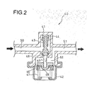
- Fig. 2 is a sectional view showing an on-demand pressure regulator which can be applied to the fuel pump module according to one embodiment of the invention.
- the on-demand pressure regulator shown in Fig. 2 may be also used.
- An oil passage 50 into which fuel pressure-fed by the drive motor is taken in and an oil passage 51 for discharging fuel into fuel injection system and others are provided to an upper casing 41 of the on-demand pressure regulator 40.
- the fuel pump module As described above, according to the fuel pump module disclosed in the invention, as the impeller for pressure-feeding fuel is arranged on the side of the bottom plate of the fuel tank according to the counter flow system, the fuel passage from the inlet of the fuel to the discharge port is shortened and as a long fuel passage required when fuel discharged from an upper end of the fuel pump module is led to a lower end of the fuel pump module is not required, the fuel pump module can be small-sized. As the on-demand pressure regulator can be arranged at the lower end of the fuel pump module, the fuel pump module can be further small-sized.
- each part and the fuel passages respectively forming the fuel pump module and a type of the drive motor are not limited to those in the embodiment and it need scarcely be said that various transformations are possible.
Landscapes
- Engineering & Computer Science (AREA)
- Mechanical Engineering (AREA)
- General Engineering & Computer Science (AREA)
- Chemical & Material Sciences (AREA)
- Combustion & Propulsion (AREA)
- Structures Of Non-Positive Displacement Pumps (AREA)
Abstract
Description
- The present invention relates to a fuel pump module, particularly relates to a fuel pump module that reduces a fuel passage, inhibits the loss of pressure and can small-size the whole module.
- So far, the configuration of a motor-driven fuel pump for pressure-feeding fuel to a fuel injection system and others that the whole fuel pump or the substantial whole fuel pump is arranged in a fuel tank is known.
- In patent document
JP-A No. 2003-97375 - However, there is a case in which structure that a fuel pump is attached on the side of a bottom plate of a fuel tank and fuel is taken in from the bottom side of the fuel tank is adopted. In this case, when the structure of the fuel pump disclosed in the above-mentioned patent document is utilized as it is, a fuel passage for discharging fuel once sucked on the upside of the fuel pump outside from the bottom side of the fuel tank is required to be provided. Hereby, a problem that the fuel passage having substantially equal length to the full height of the fuel pump is required and the whole fuel pump is simply large-sized because of the increase of components occurs.
- The object of the invention is to provide a fuel pump module that addresses the above-mentioned problem of the related art, reduces a fuel passage, inhibits the loss of pressure and can small-size the whole module.
- This object is achieved by the full pump module defined in claim 1. To achieve the above object, the invention is based upon a fuel pump module provided with a fuel pump in which an impeller provided in a lower part of the fuel pump is arranged so that its rotation axis is perpendicular and which is attached to the bottom of a fuel tank and an on-demand pressure regulator for regulating the pressure of fuel discharged from the fuel pump, and has such a first aspect that the fuel pump module is provided with the impeller configured according to a counter flow system that taken fuel is guided in a reverse direction to a direction in which the fuel is taken in, an intake passage for leading the fuel from an inlet provided on the downside of the fuel pump to the downside of the impeller and a discharge passage for guiding the fuel discharged from the impeller to the on-demand pressure regulator provided on the downside of the fuel pump.
- Besides, the invention has such a second aspect that the impeller is attached on the side of one end of an output shaft of a drive motor and the on-demand pressure regulator is provided in the vicinity of a discharge port of the impeller.
- Further, the invention has such a third aspect that the fuel pump module is configured by a cylindrical upper case for housing the drive motor and the impeller and a lower case for housing the on-demand pressure regulator, the upper case and the lower case are detachably configured, a snap fitting as a fitting member is formed in the lower case and a stopper fitted to the snap fitting is formed in the upper case.
- According to an aspect of the invention, as the impeller for pressure-feeding fuel is arranged on the side of the bottom plate of the fuel tank according to the counter flow system, a fuel passage from the inlet of fuel to the discharge port can be greatly reduced. Besides, as a long fuel passage is not required, the loss of pressure due to passage resistance is reduced and the fuel pump module can be small-sized. Further, as a long fuel passage is not required, each part can be simplified and small-sized.
- According to another aspect of the invention, as the on-demand pressure regulator can be arranged at the lower end of the fuel pump, the fuel pump module can be further small-sized.
- According to still another aspect of the invention, as the upper case and the lower case can be detached, the assembly of the fuel pump module and the maintenance of the on-demand pressure regulator and the drive motor are facilitated. The upper case and the lower case can be easily attached or detached without using a separate connecting part such as a screw.
- Further features and advantages of the invention will become apparent from the description which follows by way of nonlimiting example with reference to the enclosed drawings wherein:
- fig. 1 is a sectional view showing a fuel pump module according to one embodiment of the invention; and
- fig. 2 is a sectional view showing an on-demand pressure regulator according to one embodiment of the invention.
- Referring to the drawings, a preferred embodiment of the invention will be described in detail below. Fig. 1 is a sectional view showing a fuel pump module 1 according to one embodiment of the invention. The fuel pump module 1 is a device for pressure-feeding gasoline and others in a fuel tank to a fuel injection system by the torque of a drive motor and is attached so that the substantial whole of the fuel pump module 1 is housed in a substantially circular opening provided to
steel plates - The fuel pump module 1 is provided with a cylindrical
upper case 4 and alower case 36 respectively formed by hard resin and others. In theupper case 4, the drive motor formed by arotor 8 integrally rotated with anoutput shaft 6 and astator 7 arranged inside theupper case 4 is housed. Animpeller 9 is fixedly supported at a lower end of theoutput shaft 6 and can be driven at arbitrary revolution speed by supplying electric power via apower terminal 3 integrated with alid member 2 arranged on theupper case 4. Electric power is supplied to thepower terminal 3 by taking in external electric power by an onboard battery and the like from anelectrode 11 provided outside the fuel tank and coupling anelectrode 10 integrated with theelectrode 11 and thepower terminal 3 via a distribution cord (not shown) having a connector at both ends. - Fuel taken in from an
inlet 15 provided to theupper case 4 according to the drive of theimpeller 9 is fed to theimpeller 9 via anoil passage 16. The fuel discharged from theimpeller 9 is pressure-fed from adischarge port 18 into anoil reservoir 37. That is, theimpeller 9 practices a counter flow system in which fuel taken in from one side is discharged in the same direction as one side, theinlet 15 and theoil passage 16 function as an intake passage, and thedischarge port 18 and theoil reservoir 37 function as a discharge passage. - On the reverse side to the
oil passage 16 with theimpeller 9 between theoil passage 16 and anoil passage 17, theoil passage 17 communicating withspace 23 for housing therotor 8 is provided and when theimpeller 9 is driven, thehousing space 23 is filled with the fuel. Therefore, while theimpeller 9 is driven, therotor 8 and others are lubricated by fuel inside thehousing space 23. - An on-
demand pressure regulator 30 for supplying only a required fuel flow rate to control so that pressure generated in afuel passage 19 is appropriate is arranged between theoil reservoir 37 and thefuel passage 19. The on-demand pressure regulator 30 housed in thelower case 36 is configured by aspherical valve 31, apressure regulating member 33 that fixedly supports a shaft touched to thevalve 31 and adiaphragm 32, and aspring 34 for applying momentum for always pushing up thepressure regulating member 33 upward in the drawing. Thepressure regulating member 33 is pushed up upward in the drawing by the momentum of thespring 34 when the pressure generated in thefuel passage 19 is equal to or lower than a predetermined value. At this time, as thevalve 31 is not touched to a wall of theoil reservoir 37 because the valve is pushed up upward by thepressure regulating member 33, theoil reservoir 37 and thefuel passage 19 are communicated with each other. - In the meantime, as the device is configured so that pressing force depending upon pressure applied to the
diaphragm 32 exceeds the momentum of thespring 34 when pressure applied to thefuel passage 19 exceeds the predetermined value, thepressure regulating member 33 is pushed down downward in the drawing, and thevalve 31 abuts on the wall of theoil reservoir 37. Hereby, the communication of theoil reservoir 37 and thefuel passage 19 is broken and the supply of fuel to thefuel passage 19 is temporarily stopped. When pressure applied to thefuel passage 19 is restored in an appropriate range again, thevalve 31 is opened by the momentum of thespring 34 and the supply of fuel is resumed. Fuel pressure-fed into thefuel passage 19 is discharged from adischarge port 22 formed in aholder 21 for connecting thelower case 36 and a fuel hose after the fuel passes acheck valve 20. Thecheck valve 20 is provided to prevent the back flow of fuel and hold pressure generated in a passage on the opposite side of thedischarge port 22. - The
upper case 4 and thelower case 36 are configured so that they can be simply detached via a snap fitting structure. In thelower case 36, a snap fitting 5 as a fitting member is formed in a cylindrical part inside the fuel tank. Thesnap fitting 5 is configured so that the snap fitting is fitted to astopper 35 formed on a periphery of theupper case 4, when theupper case 4 is pushed into thelower case 36, widening the snap fitting 5 in a peripheral direction, thestopper 35 is fitted to the snap fitting in a predetermined position, and theupper case 4 and thelower case 36 are connected to each other. Similarly, as theupper case 4 can be detached from thelower case 36 when the snap fitting 5 is widened in the peripheral direction, detaching work can be performed without using a connecting part such as a screw. - Fig. 2 is a sectional view showing an on-demand pressure regulator which can be applied to the fuel pump module according to one embodiment of the invention. In place of the on-
demand pressure regulator 30 shown in Fig. 1 and in the fuel pump module 1, the on-demand pressure regulator shown in Fig. 2 may be also used. Anoil passage 50 into which fuel pressure-fed by the drive motor is taken in and anoil passage 51 for discharging fuel into fuel injection system and others are provided to anupper casing 41 of the on-demand pressure regulator 40. Avalve 43 for breaking the communication of theoil passage 50 and anoil reservoir 52, a spring 44 for applying momentum for always pushing down thevalve 43 downward in the drawing, alower casing 42 connected to theupper casing 41 with a diaphragm 46 between both casings, a pressure regulating member 48 for fixedly supporting a shaft 45 abutting on thevalve 43 and the diaphragm 46, and aspring 47 for applying momentum for always pushing up the pressure regulating member 48 upward in the drawing are provided between theoil passage 50 and theoil passage 51. - When pressure generated in the
oil passage 51 is equal to or lower than a predetermined value, the pressure regulating member 48 is pushed up upward in the drawing by the momentum of thespring 47. The reason therefor is that the momentum of thespring 47 is set so that it is larger than the momentum of the spring 44 and at this time, as thevalve 43 is pushed up upward by the shaft 45 and the valve does not abut on a sealing part 49 formed in theupper casing 41, theoil passage 50, theoil reservoir 52 and theoil passage 51 are communicated with each other. In the meantime, as pressing force depending upon pressure applied to the diaphragm 46 is set so that the pressing force exceeds the momentum of thespring 47 when pressure applied to theoil passage 51 exceeds the predetermined value, the pressure regulating member 48 is pushed down downward in the drawing, and thevalve 43 abuts on the sealing part 49. - As described above, according to the fuel pump module disclosed in the invention, as the impeller for pressure-feeding fuel is arranged on the side of the bottom plate of the fuel tank according to the counter flow system, the fuel passage from the inlet of the fuel to the discharge port is shortened and as a long fuel passage required when fuel discharged from an upper end of the fuel pump module is led to a lower end of the fuel pump module is not required, the fuel pump module can be small-sized. As the on-demand pressure regulator can be arranged at the lower end of the fuel pump module, the fuel pump module can be further small-sized.
- The form of each part and the fuel passages respectively forming the fuel pump module and a type of the drive motor are not limited to those in the embodiment and it need scarcely be said that various transformations are possible.
-
- 1...
- Fuel pump module
- 2...
- Lid member
- 3...
- Power terminal
- 4...
- Upper case
- 5...
- Snap fitting
- 6...
- Output shaft
- 7 ...
- Stator
- 8 ...
- Rotor
- 9...
- Impeller
- 10, 11...
- Electrode
- 12, 13...
- Steel plate (Bottom plate)
- 15...
- Inlet
- 16, 17...
- Oil passage
- 18.
- Discharge port
- 19...
- Fuel passage
- 23 ...
- Housing space
- 30...
- On-demand pressure regulator
- 31...
- Valve
- 32...
- Diaphragm
- 33...
- Pressure regulating member
- 34...
- Spring
- 35 ...
- Stopper
- 36 ...
- Lower case
- 37...
- Oil reservoir
- 41...
- Upper casing
- 42...
- Lower casing
- 43...
- Valve
- 44, 47...
- Springs
- 45...
- Shaft
- 46...
- Diaphragm
- 48...
- Pressure regulation member
- 49...
- Sealing part
- 50...
- Inlet
- 51...
- Outlet
- 52...
- Reservoir
Claims (3)
- A fuel pump module (1) provided with a fuel pump in which an impeller (9) provided in a lower part of the fuel pump is arranged so that its rotation axis is perpendicular and which is attached to the bottom (12, 13) of a fuel tank and an on-demand pressure regulator (30) that regulates the pressure of fuel discharged from the fuel pump, comprising:the impeller (9) configured according to a counter flow system in which taken fuel is guided in a reverse direction to a direction in which the fuel is taken in;an intake passage (16) that leads fuel from an inlet (15) provided on the downside of the fuel pump to the downside of the impeller (9); anda discharge passage (18) that guides the fuel discharged from the impeller (9) to the on-demand pressure regulator (30) provided on the downside of the fuel pump.
- The fuel pump module (1) according to Claim 1, wherein:the impeller (9) is attached on the side of one end of an output shaft (6) of a drive motor (7, 8); andthe on-demand pressure regulator (30) is provided in the vicinity of a discharge port of the impeller (9).
- The fuel pump module (1) according to Claim 1 or 2, wherein:the fuel pump module (1) comprises a cylindrical upper case (4) that houses the drive motor (7, 8) and the impeller (9) and a lower case (36) that houses the on-demand pressure regulator (30);the upper case (4) and the lower case (36) are detachably configured;in the lower case (36), a snap fitting (5) as a fitting member is formed; andin the upper case (4), a stopper (35) fitted to the snap fitting (5) is formed.
Applications Claiming Priority (1)
| Application Number | Priority Date | Filing Date | Title |
|---|---|---|---|
| JP2005377403A JP4428573B2 (en) | 2005-12-28 | 2005-12-28 | Fuel pump module |
Publications (2)
| Publication Number | Publication Date |
|---|---|
| EP1803926A1 true EP1803926A1 (en) | 2007-07-04 |
| EP1803926B1 EP1803926B1 (en) | 2012-04-18 |
Family
ID=37846088
Family Applications (1)
| Application Number | Title | Priority Date | Filing Date |
|---|---|---|---|
| EP20060127014 Not-in-force EP1803926B1 (en) | 2005-12-28 | 2006-12-22 | Fuel pump module |
Country Status (6)
| Country | Link |
|---|---|
| EP (1) | EP1803926B1 (en) |
| JP (1) | JP4428573B2 (en) |
| CN (1) | CN100462546C (en) |
| ES (1) | ES2386454T3 (en) |
| MY (1) | MY149677A (en) |
| TW (1) | TW200726906A (en) |
Families Citing this family (5)
| Publication number | Priority date | Publication date | Assignee | Title |
|---|---|---|---|---|
| JP2010116793A (en) * | 2008-11-11 | 2010-05-27 | Mitsuba Corp | Fuel supply device |
| DE102010004614B4 (en) * | 2010-01-13 | 2025-03-13 | Vitesco Technologies GmbH | Device for providing liquid reducing agent |
| TWI473739B (en) * | 2012-02-03 | 2015-02-21 | Honda Motor Co Ltd | Structure for mounting fuel pump to fuel tank |
| JP7221121B2 (en) * | 2019-04-18 | 2023-02-13 | 愛三工業株式会社 | fuel supply |
| US11441523B1 (en) * | 2021-04-16 | 2022-09-13 | Delphi Technologies Ip Limited | Fuel pump driven by an electric motor |
Citations (4)
| Publication number | Priority date | Publication date | Assignee | Title |
|---|---|---|---|---|
| GB1309926A (en) | 1969-05-28 | 1973-03-14 | Bosch Gmbh Robert | Hydraulic units |
| US4650404A (en) * | 1984-04-05 | 1987-03-17 | Nippondenso Co., Ltd. | Motor-driven fuel pump |
| EP1388664A2 (en) * | 2002-08-05 | 2004-02-11 | Denso Corporation | Pump module |
| US20050274361A1 (en) | 2004-06-14 | 2005-12-15 | Aisan Kogyo Kabushiki Kaisha | Fuel supply device for fuel returnless system |
Family Cites Families (3)
| Publication number | Priority date | Publication date | Assignee | Title |
|---|---|---|---|---|
| US6068454A (en) * | 1998-04-06 | 2000-05-30 | Ford Motor Company | Fuel pump with helical impeller |
| EP1059436A1 (en) * | 1998-12-28 | 2000-12-13 | Mitsubishi Denki Kabushiki Kaisha | Electric fuel pump |
| JP2004360678A (en) * | 2003-05-15 | 2004-12-24 | Denso Corp | Fuel pump |
-
2005
- 2005-12-28 JP JP2005377403A patent/JP4428573B2/en not_active Expired - Fee Related
-
2006
- 2006-11-01 TW TW095140457A patent/TW200726906A/en unknown
- 2006-12-22 ES ES06127014T patent/ES2386454T3/en active Active
- 2006-12-22 EP EP20060127014 patent/EP1803926B1/en not_active Not-in-force
- 2006-12-22 MY MYPI20064761 patent/MY149677A/en unknown
- 2006-12-22 CN CNB2006101711129A patent/CN100462546C/en not_active Expired - Fee Related
Patent Citations (4)
| Publication number | Priority date | Publication date | Assignee | Title |
|---|---|---|---|---|
| GB1309926A (en) | 1969-05-28 | 1973-03-14 | Bosch Gmbh Robert | Hydraulic units |
| US4650404A (en) * | 1984-04-05 | 1987-03-17 | Nippondenso Co., Ltd. | Motor-driven fuel pump |
| EP1388664A2 (en) * | 2002-08-05 | 2004-02-11 | Denso Corporation | Pump module |
| US20050274361A1 (en) | 2004-06-14 | 2005-12-15 | Aisan Kogyo Kabushiki Kaisha | Fuel supply device for fuel returnless system |
Also Published As
| Publication number | Publication date |
|---|---|
| MY149677A (en) | 2013-09-30 |
| TWI314182B (en) | 2009-09-01 |
| ES2386454T3 (en) | 2012-08-21 |
| CN100462546C (en) | 2009-02-18 |
| JP2007177702A (en) | 2007-07-12 |
| EP1803926B1 (en) | 2012-04-18 |
| JP4428573B2 (en) | 2010-03-10 |
| TW200726906A (en) | 2007-07-16 |
| CN1991160A (en) | 2007-07-04 |
Similar Documents
| Publication | Publication Date | Title |
|---|---|---|
| CN101939532A (en) | Fuel delivery system for an engine | |
| EP1302704B1 (en) | Submerged electric fluid pump | |
| JP4788730B2 (en) | Fuel supply device | |
| EP1803926A1 (en) | Fuel pump module | |
| JP4923123B2 (en) | Fuel supply device | |
| CN118159759A (en) | Power equipment for motor vehicles with multifunctional cover | |
| JP2012097640A (en) | Fuel supply apparatus | |
| JP5012614B2 (en) | Fuel supply device | |
| JP4552994B2 (en) | Fuel supply device | |
| JP6661736B1 (en) | Fuel supply device | |
| JP2015045270A (en) | Fuel pump module and manufacturing method thereof | |
| JP4922868B2 (en) | Fuel supply device | |
| CN101070830B (en) | Hydraulic unit | |
| JP5248312B2 (en) | Fuel supply device | |
| JP4871400B2 (en) | Fuel supply device | |
| JP2008157055A (en) | Fuel supply device | |
| JP6716003B1 (en) | Fuel supply device | |
| JP4821678B2 (en) | Pumping unit | |
| CN101171418A (en) | Fuel supply device | |
| CN1245866A (en) | Equipment for conveying fuel by means of fuel conveying unit placed in shell body | |
| CN103270287B (en) | Fuel supplying device | |
| US2969741A (en) | Impeller pump and motor-pump unit | |
| CN118019929A (en) | Power plant for a motor vehicle having a working medium tank built into the housing | |
| KR100727786B1 (en) | Vehicle fuel pump structure and fuel supply device | |
| EP1985837B1 (en) | Fuel delivery module |
Legal Events
| Date | Code | Title | Description |
|---|---|---|---|
| PUAI | Public reference made under article 153(3) epc to a published international application that has entered the european phase |
Free format text: ORIGINAL CODE: 0009012 |
|
| AK | Designated contracting states |
Kind code of ref document: A1 Designated state(s): AT BE BG CH CY CZ DE DK EE ES FI FR GB GR HU IE IS IT LI LT LU LV MC NL PL PT RO SE SI SK TR |
|
| AX | Request for extension of the european patent |
Extension state: AL BA HR MK YU |
|
| 17P | Request for examination filed |
Effective date: 20071227 |
|
| 17Q | First examination report despatched |
Effective date: 20080131 |
|
| AKX | Designation fees paid |
Designated state(s): ES IT |
|
| REG | Reference to a national code |
Ref country code: DE Ref legal event code: 8566 |
|
| GRAP | Despatch of communication of intention to grant a patent |
Free format text: ORIGINAL CODE: EPIDOSNIGR1 |
|
| GRAS | Grant fee paid |
Free format text: ORIGINAL CODE: EPIDOSNIGR3 |
|
| GRAA | (expected) grant |
Free format text: ORIGINAL CODE: 0009210 |
|
| AK | Designated contracting states |
Kind code of ref document: B1 Designated state(s): ES IT |
|
| REG | Reference to a national code |
Ref country code: ES Ref legal event code: FG2A Ref document number: 2386454 Country of ref document: ES Kind code of ref document: T3 Effective date: 20120821 |
|
| PLBE | No opposition filed within time limit |
Free format text: ORIGINAL CODE: 0009261 |
|
| STAA | Information on the status of an ep patent application or granted ep patent |
Free format text: STATUS: NO OPPOSITION FILED WITHIN TIME LIMIT |
|
| 26N | No opposition filed |
Effective date: 20130121 |
|
| PGFP | Annual fee paid to national office [announced via postgrant information from national office to epo] |
Ref country code: ES Payment date: 20180102 Year of fee payment: 12 |
|
| PGFP | Annual fee paid to national office [announced via postgrant information from national office to epo] |
Ref country code: IT Payment date: 20181220 Year of fee payment: 13 |
|
| REG | Reference to a national code |
Ref country code: ES Ref legal event code: FD2A Effective date: 20200205 |
|
| PG25 | Lapsed in a contracting state [announced via postgrant information from national office to epo] |
Ref country code: ES Free format text: LAPSE BECAUSE OF NON-PAYMENT OF DUE FEES Effective date: 20181223 |
|
| PG25 | Lapsed in a contracting state [announced via postgrant information from national office to epo] |
Ref country code: IT Free format text: LAPSE BECAUSE OF NON-PAYMENT OF DUE FEES Effective date: 20191222 |