EP1801826A1 - Thick film capacitors on ceramic interconnect substrates - Google Patents
Thick film capacitors on ceramic interconnect substrates Download PDFInfo
- Publication number
- EP1801826A1 EP1801826A1 EP06026011A EP06026011A EP1801826A1 EP 1801826 A1 EP1801826 A1 EP 1801826A1 EP 06026011 A EP06026011 A EP 06026011A EP 06026011 A EP06026011 A EP 06026011A EP 1801826 A1 EP1801826 A1 EP 1801826A1
- Authority
- EP
- European Patent Office
- Prior art keywords
- conductive layer
- ceramic
- dielectric
- forming
- capacitor
- Prior art date
- Legal status (The legal status is an assumption and is not a legal conclusion. Google has not performed a legal analysis and makes no representation as to the accuracy of the status listed.)
- Withdrawn
Links
Images


Classifications
-
- H—ELECTRICITY
- H01—ELECTRIC ELEMENTS
- H01G—CAPACITORS; CAPACITORS, RECTIFIERS, DETECTORS, SWITCHING DEVICES, LIGHT-SENSITIVE OR TEMPERATURE-SENSITIVE DEVICES OF THE ELECTROLYTIC TYPE
- H01G4/00—Fixed capacitors; Processes of their manufacture
- H01G4/002—Details
- H01G4/018—Dielectrics
- H01G4/06—Solid dielectrics
- H01G4/08—Inorganic dielectrics
- H01G4/12—Ceramic dielectrics
-
- H—ELECTRICITY
- H01—ELECTRIC ELEMENTS
- H01G—CAPACITORS; CAPACITORS, RECTIFIERS, DETECTORS, SWITCHING DEVICES, LIGHT-SENSITIVE OR TEMPERATURE-SENSITIVE DEVICES OF THE ELECTROLYTIC TYPE
- H01G4/00—Fixed capacitors; Processes of their manufacture
- H01G4/30—Stacked capacitors
-
- H—ELECTRICITY
- H01—ELECTRIC ELEMENTS
- H01G—CAPACITORS; CAPACITORS, RECTIFIERS, DETECTORS, SWITCHING DEVICES, LIGHT-SENSITIVE OR TEMPERATURE-SENSITIVE DEVICES OF THE ELECTROLYTIC TYPE
- H01G4/00—Fixed capacitors; Processes of their manufacture
- H01G4/002—Details
- H01G4/228—Terminals
- H01G4/232—Terminals electrically connecting two or more layers of a stacked or rolled capacitor
-
- H—ELECTRICITY
- H01—ELECTRIC ELEMENTS
- H01G—CAPACITORS; CAPACITORS, RECTIFIERS, DETECTORS, SWITCHING DEVICES, LIGHT-SENSITIVE OR TEMPERATURE-SENSITIVE DEVICES OF THE ELECTROLYTIC TYPE
- H01G4/00—Fixed capacitors; Processes of their manufacture
- H01G4/33—Thin- or thick-film capacitors (thin- or thick-film circuits; capacitors without a potential-jump or surface barrier specially adapted for integrated circuits, details thereof, multistep manufacturing processes therefor)
-
- H—ELECTRICITY
- H05—ELECTRIC TECHNIQUES NOT OTHERWISE PROVIDED FOR
- H05K—PRINTED CIRCUITS; CASINGS OR CONSTRUCTIONAL DETAILS OF ELECTRIC APPARATUS; MANUFACTURE OF ASSEMBLAGES OF ELECTRICAL COMPONENTS
- H05K1/00—Printed circuits
- H05K1/16—Printed circuits incorporating printed electric components, e.g. printed resistors, capacitors or inductors
-
- H—ELECTRICITY
- H05—ELECTRIC TECHNIQUES NOT OTHERWISE PROVIDED FOR
- H05K—PRINTED CIRCUITS; CASINGS OR CONSTRUCTIONAL DETAILS OF ELECTRIC APPARATUS; MANUFACTURE OF ASSEMBLAGES OF ELECTRICAL COMPONENTS
- H05K1/00—Printed circuits
- H05K1/16—Printed circuits incorporating printed electric components, e.g. printed resistors, capacitors or inductors
- H05K1/162—Printed circuits incorporating printed electric components, e.g. printed resistors, capacitors or inductors incorporating printed capacitors
-
- H—ELECTRICITY
- H10—SEMICONDUCTOR DEVICES; ELECTRIC SOLID-STATE DEVICES NOT OTHERWISE PROVIDED FOR
- H10D—INORGANIC ELECTRIC SEMICONDUCTOR DEVICES
- H10D86/00—Integrated devices formed in or on insulating or conducting substrates, e.g. formed in silicon-on-insulator [SOI] substrates or on stainless steel or glass substrates
- H10D86/80—Integrated devices formed in or on insulating or conducting substrates, e.g. formed in silicon-on-insulator [SOI] substrates or on stainless steel or glass substrates characterised by multiple passive components, e.g. resistors, capacitors or inductors
- H10D86/85—Integrated devices formed in or on insulating or conducting substrates, e.g. formed in silicon-on-insulator [SOI] substrates or on stainless steel or glass substrates characterised by multiple passive components, e.g. resistors, capacitors or inductors characterised by only passive components
-
- H—ELECTRICITY
- H05—ELECTRIC TECHNIQUES NOT OTHERWISE PROVIDED FOR
- H05K—PRINTED CIRCUITS; CASINGS OR CONSTRUCTIONAL DETAILS OF ELECTRIC APPARATUS; MANUFACTURE OF ASSEMBLAGES OF ELECTRICAL COMPONENTS
- H05K1/00—Printed circuits
- H05K1/02—Details
- H05K1/03—Use of materials for the substrate
- H05K1/0306—Inorganic insulating substrates, e.g. ceramic, glass
-
- H—ELECTRICITY
- H05—ELECTRIC TECHNIQUES NOT OTHERWISE PROVIDED FOR
- H05K—PRINTED CIRCUITS; CASINGS OR CONSTRUCTIONAL DETAILS OF ELECTRIC APPARATUS; MANUFACTURE OF ASSEMBLAGES OF ELECTRICAL COMPONENTS
- H05K1/00—Printed circuits
- H05K1/02—Details
- H05K1/09—Use of materials for the conductive, e.g. metallic pattern
- H05K1/092—Dispersed materials, e.g. conductive pastes or inks
-
- H—ELECTRICITY
- H05—ELECTRIC TECHNIQUES NOT OTHERWISE PROVIDED FOR
- H05K—PRINTED CIRCUITS; CASINGS OR CONSTRUCTIONAL DETAILS OF ELECTRIC APPARATUS; MANUFACTURE OF ASSEMBLAGES OF ELECTRICAL COMPONENTS
- H05K2201/00—Indexing scheme relating to printed circuits covered by H05K1/00
- H05K2201/09—Shape and layout
- H05K2201/09209—Shape and layout details of conductors
- H05K2201/09654—Shape and layout details of conductors covering at least two types of conductors provided for in H05K2201/09218 - H05K2201/095
- H05K2201/09763—Printed component having superposed conductors, but integrated in one circuit layer
-
- H—ELECTRICITY
- H05—ELECTRIC TECHNIQUES NOT OTHERWISE PROVIDED FOR
- H05K—PRINTED CIRCUITS; CASINGS OR CONSTRUCTIONAL DETAILS OF ELECTRIC APPARATUS; MANUFACTURE OF ASSEMBLAGES OF ELECTRICAL COMPONENTS
- H05K2201/00—Indexing scheme relating to printed circuits covered by H05K1/00
- H05K2201/10—Details of components or other objects attached to or integrated in a printed circuit board
- H05K2201/10431—Details of mounted components
- H05K2201/10507—Involving several components
- H05K2201/10515—Stacked components
-
- H—ELECTRICITY
- H05—ELECTRIC TECHNIQUES NOT OTHERWISE PROVIDED FOR
- H05K—PRINTED CIRCUITS; CASINGS OR CONSTRUCTIONAL DETAILS OF ELECTRIC APPARATUS; MANUFACTURE OF ASSEMBLAGES OF ELECTRICAL COMPONENTS
- H05K2201/00—Indexing scheme relating to printed circuits covered by H05K1/00
- H05K2201/10—Details of components or other objects attached to or integrated in a printed circuit board
- H05K2201/10613—Details of electrical connections of non-printed components, e.g. special leads
- H05K2201/10621—Components characterised by their electrical contacts
- H05K2201/10689—Leaded Integrated Circuit [IC] package, e.g. dual-in-line [DIL]
-
- H—ELECTRICITY
- H10—SEMICONDUCTOR DEVICES; ELECTRIC SOLID-STATE DEVICES NOT OTHERWISE PROVIDED FOR
- H10W—GENERIC PACKAGES, INTERCONNECTIONS, CONNECTORS OR OTHER CONSTRUCTIONAL DETAILS OF DEVICES COVERED BY CLASS H10
- H10W44/00—Electrical arrangements for controlling or matching impedance
- H10W44/20—Electrical arrangements for controlling or matching impedance at high-frequency [HF] or radio frequency [RF]
-
- H—ELECTRICITY
- H10—SEMICONDUCTOR DEVICES; ELECTRIC SOLID-STATE DEVICES NOT OTHERWISE PROVIDED FOR
- H10W—GENERIC PACKAGES, INTERCONNECTIONS, CONNECTORS OR OTHER CONSTRUCTIONAL DETAILS OF DEVICES COVERED BY CLASS H10
- H10W72/00—Interconnections or connectors in packages
Definitions
- the present invention relates to thick-film capacitors, more particularly to thick-film capacitors formed on ceramic substrates.
- the microprocessor will experience a voltage drop or power droop that will exceed the allowable ripple voltage and noise margin and the IC will trigger false gates. Additionally, as the IC powers up, a slow response time will result in power overshoot. Power droop and overshoot must be maintained within allowable limits by the use of capacitors that are close enough to the IC that they provide or absorb power within the appropriate response time.
- Capacitors for dampening power droop or overshoot are generally placed as close to the IC as possible in order to improve their performance.
- Conventional designs have capacitors surface mounted on an interconnect substrate and clustered around the lC that is mounted on the same interconnect substrate. In this arrangement, large numbers of capacitors requires complex electrical routing, which leads to increased inductance. As frequencies increase and operating voltages continue to drop, the capacitance must be supplied at increasingly lower inductance levels.
- a method of making one or more thick-film capacitors on a glass or ceramic interconnect substrate comprising:
- the first conductive layer, the capacitor dielectric layer and the second conductive layer may be cofired or separately fired.
- Capacitors constructed according to the above method have high capacitance and may also have other desirable electrical and physical properties:
- the capacitors may be arranged in arrays on the surface of the glass-ceramic or ceramic interconnect so that pads connected to their terminations are aligned to the power and ground terminals of the IC. Such an arrangement would allow the capacitance to be supplied at low inductance.
- Interposer can refer to, in general, any small interconnect substrate containing capacitors or other passive components that is mounted on a printed wiring board.
- An interposer having one or more capacitors may provide capacitance for decoupling and/or controlling voltage for integrated circuit die mounted on the interposer.
- the interposer embodiments discussed in this specification can include capacitors of high capacitance density.
- “High capacitance density” in this embodiment indicates capacitance densities of approximately 150 nanoFarad/cm 2 .
- ceramic and glass-ceramic interconnect substrates are referred generally to as “ceramic interconnect substrates.”
- High capacitance capacitors on ceramic interconnect substrates have desirable electrical and physical properties.
- One desirable electrical property is low inductance because the capacitors can be placed directly beneath an IC. The electrical routing requirements are thereby minimized, considerably reducing power loop inductance.
- One desirable physical property of the ceramic capacitor embodiments is a temperature coefficient of expansion (TCE) value that is between that of an organic printed wiring board (approximately 17 x 10 -6 /°C) and that of an integrated circuit (approximately 4 - 6 x 10 -6 /°C). This property provides stress reductions between the IC and the printed wiring board, which enhances long-term reliability.
- TCE temperature coefficient of expansion
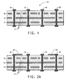
- FIG. 1 is a cross-sectional view of a ceramic interconnect substrate 10 illustrating a ground plane 14, a power plane 15, signal lines 16, the ceramic insulation layers 17, and surface pads 18 and 19 connected to the ground and power plane respectively.
- the ceramic interconnect substrate 10 has pads 18 and 19 suitably positioned for the thick-film capacitors.
- the ceramic substrate 10 may be a glass-ceramic substrate such as any commercial low temperature cofired ceramic substrate using precious metal or copper metallization made with, for example, DuPont Green Tape® materials, or any commercial high temperature cofired ceramic system using tungsten or molybdenum metallization.
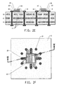
- FIGS. 2A-2F illustrate manufacturing steps of the capacitor.
- the method illustrated in FIGS. 2A-2F and discussed in detail below addresses the formation of one or two capacitors on a ceramic substrate. Several capacitors can be formed, however.
- a first conductive layer 20 is formed over the ceramic interconnect substrate 10.
- the first conductive layer 20 is used to form a first electrode of the finished capacitor and connects to the ground pads 18.
- the first conductor layer may be deposited on to the ceramic interconnect surface by a screen-printing process using a thick-film conductive paste composition.
- the first conductive layer 20 is then dried at, for example, 10 minutes at 125°C.
- the first conductive layer 20 may be fired under thick-film firing conditions to form the first electrode. The firing may take place in air at a temperature in the range of 800°C to 1050°C.
- the thickness of the fired first electrode may be approximately 3-5 microns.
- the first thick-film conductive layer 20 can be a precious metal such as platinum, palladium, gold or silver, or a base metal composition such as copper.
- a precious metal such as platinum, palladium, gold or silver
- a base metal composition such as copper.
- copper is employed due to its low cost and is hereinafter described with reference to compositions and properties.
- FIG. 2B shows a top plan view of the first electrode 20 on the surface of the ceramic interconnect layer showing a plurality of ground pads 18 and power pads 19 and other signal pads. These are designed to be connected to the appropriate ground, power and signal terminals of the IC. All ground pads 18 are connected to the first electrode 20 by conductive fingers extending out of the body of the first electrode 20.
- the article shown in FIG. 2 and 2A are views of a cross-section along the line A-A1 of FIG. 2B.
- One thick-film copper paste disclosed in U.S. Publication No. US2005/0204864 to Borland et al. and suitable for use as a first conductive layer has the following composition (amounts relative by mass): Copper powder 58.4 Glass A 1.7 Cuprous oxide powder 5.8 Vehicle 11.7 TEXANOL® solvent 12.9 Surfactant 0.5 Total 91.0 In this composition, Glass A comprises: lead germanate of the composition Pb 5 Ge 3 O 11 Vehicle comprises: Ethyl cellulose N200 11 % TEXANOL® 89% Surfactant comprises: VARIQUAT® CC-9 NS surfactant TEXANOL® is available from Eastman Chemical Co. VARIQUAT® CC-9 NS is available from Ashland Inc.
- a capacitor dielectric layer 30 is formed over the first electrode 20.
- the capacitor dielectric layer may be formed by screen-printing a thick-film capacitor dielectric paste over the first electrode 20 and on to the surface of the ceramic interconnect substrate 10.
- the dielectric layer 30 is then dried at, for example, 10 minutes at 125°C.
- One print of the thick-film capacitor dielectric paste may be sufficient to give the desired thickness.
- two prints of the capacitor dielectric paste are commonly applied, separated by a drying process, to avoid any defects formed in the first printed layer from extending through the entire capacitor dielectric thickness.
- FIG. 2D shows a top plan view of the article illustrated in FIG 2C.
- the capacitor dielectric covers the body of the first electrode layer. Only the conductive fingers extending from the first electrode are not covered by the capacitor dielectric.
- One suitable thick-film capacitor dielectric material disclosed in U.S. 2005/02070974 to Borland et al. has the following composition (amounts relative by mass): Barium titanate powder 68.55 Lithium fluoride 1.0 Barium fluoride 1.36 Zinc fluoride 0.74 Glass A 10.25 Glass B 1.0 Glass C 1.0 Vehicle 5.9 TEXANOL® solvent 8.7 Oxidizer 1.0 Phosphate wetting agent 0.5 Total 100.00
- Glass A comprises: lead germanate of the composition Pb 5 Ge 3 O 11
- Glass B comprises: Pb 4 BaGe 1.5 Si 1.5 O 11
- Glass C comprises: Pb 5 GeSiTiO 11
- Vehicle comprises: Ethyl cellulose N200 11 % TEXANOL® solvent 89%
- Oxidizer comprises: Barium nitrate powder 84% Vehicle 16%
- a conductive layer 40 is formed over the dried capacitor dielectric layer 30 by screen-printing the thick-film conductive paste composition used for the first electrode 20.
- the conductive layer 40 is also connected to the power pads 19 by conductive fingers extending out of the main body of the conductive layer.
- the conductive layer 40 is then dried at, for example, 10 minutes at 125°C.
- FIG. 2F is a top plan view of the article illustrated in FIG. 2E showing conductive fingers extending out from the electrode 40 to connect to the power pads 19.
- the surface area of the dielectric layer 30, when viewed from the top plan perspective in FIG 2F, is larger than the main bodies of the electrode 20 and 40 so that the conductive fingers extending out from the electrodes 20 and 40 are separated by the capacitor dielectric.
- the thick-film capacitor dielectric layer 30 and the thick-film conductive layer 40 may now be co-fired in nitrogen at, for example, 900°C for 10 minutes at the peak temperature, to form the capacitor dielectric and the second electrode of the capacitor.
- the glass component of the capacitor dielectric material softens and flows before the peak firing temperature is reached, coalesces and encapsulates the functional phase creating a high density film.
- dopants added to the composition may shift and depress the Curie temperature and promote appropriate grain growth to realize the desired electrical characteristics.
- the firing takes place in air.
- the first conductive layer, the capacitor dielectric layer, and the second conductive layer are cofired.
- the first conductive layer, the capacitor dielectric layer, and the second conductive layer are fired separately. Firing may take place at a temperature in the range of 800°C to 1050°C. In one embodiment, the firing takes place in an environment having a nitrogen atmosphere.
- the capacitor dielectric may have a fired thickness in the range of about 10-50 microns; in a particular embodiment, the capacitor dielectric has a thickness in the range of about 10-30 microns; in a further embodiment, the fired thickness is in the range of 15-25 microns.
- the resulting dielectric When fired in nitrogen at 900-950°C for 10 minutes at peak temperature, the resulting dielectric may have dielectric constant on the order of 3000.
- the high dielectric constant dielectric may also have Electrical Industries Association Z5U characteristics of temperature stability characteristics and a low dissipation factor.
- firing is conducted in a low oxygen partial pressure environment, such as a thick-film nitrogen-firing atmosphere.
- the burn-out zone of the furnace may be doped with small additions of oxygen to improve oxidation and removal of the thick-film organic vehicle but the firing zone is typically kept at a few parts per million oxygen. Oxidation of the base metal layers 20 and 40 is thereby avoided.
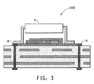
- FIG. 3 is a sectional front elevation view of an interposer package 1000 with an attached device D.
- the interposer package 1000 comprises the article of FIGS. 2E and F and the sectional view is taken along the line B-B1 of the article shown in FIG. 2F.
- the capacitor is coupled to a device D .
- the electrodes 20 are connected to the ground pads 18 which are connected to the ground terminals of the device D.
- the power terminals of the device D are similarly connected to the ground pads 19 which are connected to the electrode 40.
- the interposer package may be mounted on to a printed wiring board or another ceramic substrate.
- the device D may be, for example, an integrated circuit.
- One or more integrated circuits may be attached to capacitors on the surface of the ceramic interconnect substrate.
- capacitors and terminal pads are illustrated. Any number of such components, however, can be incorporated into a structure for supplying power to a single device or multiple devices, or for other purposes.
- multilayer capacitors can be fabricated by performing steps illustrated in FIG. 2A through 2F and repeating the steps multiple times. A plurality of individual capacitors can be formed during each process. Multiple capacitor layers are desirable because of the increased the total capacitance that can be achieved for a given projected substrate area.
- Additional circuitry can be added to the top of the thick-film capacitor interposer as described above.
- the surface can be metallized using thick-film conductors to form circuit patterns using standard thick-film techniques.
- the thick-film capacitor interposer embodiments of the present invention can be further processed by addition of other passive components onto the top of the ceramic interconnect substrate including inductors or resistors.
- Inductors are readily formed from thick-film conductors.
- Resistors may be formed using thick-film resistor compositions applied by screen printing and curing or firing.
- An encapsulant may be applied to the final structure to provide dielectric isolation or additional environmental protection to the capacitor or other components on the surface of the ceramic interconnect substrate.
- thick-film pastes comprise finely divided particles of ceramic, glass, metal, metal oxides or other solids dispersed in polymers dissolved in a mixture of dispersing agent and organic solvent.
- capacitor dielectric pastes for use with copper electrodes have an organic vehicle with good burnout in a nitrogen atmosphere.
- Such vehicles generally contain very small amounts of resin, such as high molecular weight ethyl cellulose, where only small amounts are necessary to generate a viscosity suitable for screen-printing.
- an oxidizing component such as barium nitrate powder, added to the powder mixture, helps the organic component burn out in the nitrogen atmosphere.
- Solids are mixed with an essentially inert liquid medium (the "vehicle"), then uniformly dispersed on a roll mill to form a paste-like composition suitable for screen-printing.
- Any essentially inert liquid may be used as the vehicle.
- various organic liquids, with or without thickening and/or stabilizing agents and/or other common additives, may be used as the vehicle.
- High K thick-film dielectric pastes generally contain at least one high K functional phase powder and at least one glass powder dispersed in a vehicle system composed of at least one resin and a solvent.
- the vehicle system is designed to be screen-printed to provide a dense film.
- the high K functional phase powders can comprise perovskite-type ferroelectric compositions with the general formula ABO 3 . Examples of such compositions include BaTiO 3 ; SrTiO 3 ; PbTiO 3 ; CaTiO 3 ; PbZrO 3 ; BaZrO 3 and SrZrO 3 .
- compositions are also possible by substitution of alternative elements into the A and/or B position, such as Pb(Mg 1/3 Nb 2/3 )O 3 and Pb(Zn 1/3 Nb 2/3 )O 3 .
- Pb(Mg 1/3 Nb 2/3 )O 3 and Pb(Zn 1/3 Nb 2/3 )O 3 are other possible high K materials.
- Doped and mixed metal versions of the above compositions are also suitable. Doping and mixing is done primarily to achieve the necessary end-use property specifications such as, for example, the necessary temperature coefficient of capacitance (TCC) in order for the material to meet industry definitions, such as "X7R” or "Z5U” standards.
- TCC temperature coefficient of capacitance
- the glasses in the pastes can be, for example, Ca-Al borosilicates, Pb-Ba borosilicates, Mg-Al silicates, rare earth borates, and other similar glass compositions.
- high K glass-ceramic powders such as lead germanate (Pb 5 Ge 3 O 11 ), are employed.
- Pastes used to form the electrode layers may be based on metallic powders of either copper, nickel, manganese, molybdenum, tungsten, silver, silver-containing precious metal compositions, or mixtures of these compounds. In one embodiment, copper powder compositions are employed.
- the electrode and dielectric layers are described as formed by screen-printing. Other deposition methods may also be used.
Landscapes
- Engineering & Computer Science (AREA)
- Power Engineering (AREA)
- Microelectronics & Electronic Packaging (AREA)
- Manufacturing & Machinery (AREA)
- Chemical & Material Sciences (AREA)
- Ceramic Engineering (AREA)
- Inorganic Chemistry (AREA)
- Fixed Capacitors And Capacitor Manufacturing Machines (AREA)
- Parts Printed On Printed Circuit Boards (AREA)
- Production Of Multi-Layered Print Wiring Board (AREA)
- Ceramic Capacitors (AREA)
Abstract
Description
- The present invention relates to thick-film capacitors, more particularly to thick-film capacitors formed on ceramic substrates.
- As semiconductor devices such as integrated circuits (IC) operate at higher frequencies, higher data rates and lower voltages, noise in the power and ground (return) lines and supplying sufficient current to accommodate faster circuit switching becomes an increasingly important problem requiring low impedance in the power distribution system. In order to provide low noise and stable power to the IC, impedance in conventional circuits is reduced by use of surface mount technology (SMT) capacitors interconnected in parallel. The higher operating frequencies (higher lC switching speeds) require that voltage response times to the IC be faster. Lower operating voltages require that allowable voltage variations (ripple) and noise are smaller. For example, as a microprocessor lC switches and begins an operation, it calls for power to support the switching circuit. If the response time of the voltage supply is too slow, the microprocessor will experience a voltage drop or power droop that will exceed the allowable ripple voltage and noise margin and the IC will trigger false gates. Additionally, as the IC powers up, a slow response time will result in power overshoot. Power droop and overshoot must be maintained within allowable limits by the use of capacitors that are close enough to the IC that they provide or absorb power within the appropriate response time.
- Capacitors for dampening power droop or overshoot are generally placed as close to the IC as possible in order to improve their performance. Conventional designs have capacitors surface mounted on an interconnect substrate and clustered around the lC that is mounted on the same interconnect substrate. In this arrangement, large numbers of capacitors requires complex electrical routing, which leads to increased inductance. As frequencies increase and operating voltages continue to drop, the capacitance must be supplied at increasingly lower inductance levels.
- Disclosed is a method of making one or more thick-film capacitors on a glass or ceramic interconnect substrate comprising:
- providing a previously manufactured glass-ceramic or ceramic interconnect substrate;
- forming a first conductive layer thereon, wherein forming the first conductor layer comprises forming the first conductive layer and firing at a temperature of at least about 800°C;
- forming a capacitor dielectric over the first conductive layer;
- forming a second conductive layer over the dielectric, and cofiring the capacitor dielectric and second conductive layer such that the first conductive layer, the capacitor dielectric, and the second conductive layer form a capacitor.
- The first conductive layer, the capacitor dielectric layer and the second conductive layer may be cofired or separately fired.
- Capacitors constructed according to the above method have high capacitance and may also have other desirable electrical and physical properties: The capacitors may be arranged in arrays on the surface of the glass-ceramic or ceramic interconnect so that pads connected to their terminations are aligned to the power and ground terminals of the IC. Such an arrangement would allow the capacitance to be supplied at low inductance.
-
- FIG. 1 is a sectional front elevation view of a ceramic interconnect substrate.
- FIGS. 2A-2F illustrate steps in forming a capacitor on the surface of the article of FIG. 1 according to the present embodiment.
- FIG. 3 is a sectional front elevation view of a glass-ceramic or ceramic, interconnect package along the line A-A1 connected to a device D.
- Methods of forming thick-film capacitors on ceramic and glass ceramic interconnect substrates are disclosed. The thick-film capacitors on glass-ceramic or ceramic interconnect substrates are suitable for use as, for example, mother boards or interposers. "Interposer" can refer to, in general, any small interconnect substrate containing capacitors or other passive components that is mounted on a printed wiring board. An interposer having one or more capacitors may provide capacitance for decoupling and/or controlling voltage for integrated circuit die mounted on the interposer.
- The interposer embodiments discussed in this specification can include capacitors of high capacitance density. "High capacitance density" in this embodiment indicates capacitance densities of approximately 150 nanoFarad/cm2. For the purposes of this specification, ceramic and glass-ceramic interconnect substrates are referred generally to as "ceramic interconnect substrates."
- High capacitance capacitors on ceramic interconnect substrates according to the present embodiments have desirable electrical and physical properties. One desirable electrical property is low inductance because the capacitors can be placed directly beneath an IC. The electrical routing requirements are thereby minimized, considerably reducing power loop inductance. One desirable physical property of the ceramic capacitor embodiments is a temperature coefficient of expansion (TCE) value that is between that of an organic printed wiring board (approximately 17 x 10-6/°C) and that of an integrated circuit (approximately 4 - 6 x 10⁻⁶/°C). This property provides stress reductions between the IC and the printed wiring board, which enhances long-term reliability.
- Referring to FIG. 1, a
ceramic interconnect substrate 10 is provided. FIG. 1 is a cross-sectional view of aceramic interconnect substrate 10 illustrating aground plane 14, apower plane 15,signal lines 16, theceramic insulation layers 17, andsurface pads ceramic interconnect substrate 10 haspads ceramic substrate 10 may be a glass-ceramic substrate such as any commercial low temperature cofired ceramic substrate using precious metal or copper metallization made with, for example, DuPont Green Tape® materials, or any commercial high temperature cofired ceramic system using tungsten or molybdenum metallization. - FIGS. 2A-2F illustrate manufacturing steps of the capacitor. The method illustrated in FIGS. 2A-2F and discussed in detail below addresses the formation of one or two capacitors on a ceramic substrate. Several capacitors can be formed, however.
- In FIG. 2A, a first
conductive layer 20 is formed over theceramic interconnect substrate 10. The firstconductive layer 20 is used to form a first electrode of the finished capacitor and connects to theground pads 18. The first conductor layer may be deposited on to the ceramic interconnect surface by a screen-printing process using a thick-film conductive paste composition. The firstconductive layer 20 is then dried at, for example, 10 minutes at 125°C. The firstconductive layer 20 may be fired under thick-film firing conditions to form the first electrode. The firing may take place in air at a temperature in the range of 800°C to 1050°C. The thickness of the fired first electrode may be approximately 3-5 microns. The first thick-filmconductive layer 20 can be a precious metal such as platinum, palladium, gold or silver, or a base metal composition such as copper. In a particular embodiment, copper is employed due to its low cost and is hereinafter described with reference to compositions and properties. - FIG. 2B shows a top plan view of the
first electrode 20 on the surface of the ceramic interconnect layer showing a plurality ofground pads 18 andpower pads 19 and other signal pads. These are designed to be connected to the appropriate ground, power and signal terminals of the IC. Allground pads 18 are connected to thefirst electrode 20 by conductive fingers extending out of the body of thefirst electrode 20. The article shown in FIG. 2 and 2A are views of a cross-section along the line A-A1 of FIG. 2B. - One thick-film copper paste disclosed in U.S. Publication No.
US2005/0204864 to Borland et al. and suitable for use as a first conductive layer has the following composition (amounts relative by mass):Copper powder 58.4 Glass A 1.7 Cuprous oxide powder 5.8 Vehicle 11.7 TEXANOL® solvent 12.9 Surfactant 0.5 Total 91.0 Glass A comprises: lead germanate of the composition Pb5Ge3O11 Vehicle comprises: Ethyl cellulose N200 11 % TEXANOL® 89% Surfactant comprises: VARIQUAT® CC-9 NS surfactant TEXANOL® is available from Eastman Chemical Co. VARIQUAT® CC-9 NS is available from Ashland Inc. - In step FIG. 2C, a
capacitor dielectric layer 30 is formed over thefirst electrode 20. The capacitor dielectric layer may be formed by screen-printing a thick-film capacitor dielectric paste over thefirst electrode 20 and on to the surface of theceramic interconnect substrate 10. Thedielectric layer 30 is then dried at, for example, 10 minutes at 125°C. One print of the thick-film capacitor dielectric paste may be sufficient to give the desired thickness. However, two prints of the capacitor dielectric paste are commonly applied, separated by a drying process, to avoid any defects formed in the first printed layer from extending through the entire capacitor dielectric thickness. - FIG. 2D shows a top plan view of the article illustrated in FIG 2C. The capacitor dielectric covers the body of the first electrode layer. Only the conductive fingers extending from the first electrode are not covered by the capacitor dielectric.
- One suitable thick-film capacitor dielectric material disclosed in
U.S. 2005/02070974 to Borland et al. Barium titanate powder 68.55 Lithium fluoride 1.0 Barium fluoride 1.36 Zinc fluoride 0.74 Glass A 10.25 Glass B 1.0 Glass C 1.0 Vehicle 5.9 TEXANOL® solvent 8.7 Oxidizer 1.0 Phosphate wetting agent 0.5 Total 100.00 Glass A comprises: lead germanate of the composition Pb5Ge3O11 Glass B comprises: Pb4BaGe1.5 Si1.5 O11 Glass C comprises: Pb5GeSiTiO11 Vehicle comprises: Ethyl cellulose N200 11 % TEXANOL® solvent 89% Oxidizer comprises: Barium nitrate powder 84 % Vehicle 16% - In step FIG. 2E, a
conductive layer 40 is formed over the driedcapacitor dielectric layer 30 by screen-printing the thick-film conductive paste composition used for thefirst electrode 20. Theconductive layer 40 is also connected to thepower pads 19 by conductive fingers extending out of the main body of the conductive layer. Theconductive layer 40 is then dried at, for example, 10 minutes at 125°C. - FIG. 2F is a top plan view of the article illustrated in FIG. 2E showing conductive fingers extending out from the
electrode 40 to connect to thepower pads 19. The surface area of thedielectric layer 30, when viewed from the top plan perspective in FIG 2F, is larger than the main bodies of theelectrode electrodes - The thick-film
capacitor dielectric layer 30 and the thick-film conductive layer 40 may now be co-fired in nitrogen at, for example, 900°C for 10 minutes at the peak temperature, to form the capacitor dielectric and the second electrode of the capacitor. During firing, the glass component of the capacitor dielectric material softens and flows before the peak firing temperature is reached, coalesces and encapsulates the functional phase creating a high density film. In addition, dopants added to the composition may shift and depress the Curie temperature and promote appropriate grain growth to realize the desired electrical characteristics. In one embodiment, the firing takes place in air. In a further embodiment, the first conductive layer, the capacitor dielectric layer, and the second conductive layer are cofired. In still a further embodiment, the first conductive layer, the capacitor dielectric layer, and the second conductive layer are fired separately. Firing may take place at a temperature in the range of 800°C to 1050°C. In one embodiment, the firing takes place in an environment having a nitrogen atmosphere. - The capacitor dielectric may have a fired thickness in the range of about 10-50 microns; in a particular embodiment, the capacitor dielectric has a thickness in the range of about 10-30 microns; in a further embodiment, the fired thickness is in the range of 15-25 microns. When fired in nitrogen at 900-950°C for 10 minutes at peak temperature, the resulting dielectric may have dielectric constant on the order of 3000. The high dielectric constant dielectric may also have Electrical Industries Association Z5U characteristics of temperature stability characteristics and a low dissipation factor.
- When using a base metal such as copper to form the first and
second electrodes - FIG. 3 is a sectional front elevation view of an
interposer package 1000 with an attached device D. Theinterposer package 1000 comprises the article of FIGS. 2E and F and the sectional view is taken along the line B-B1 of the article shown in FIG. 2F. The capacitor is coupled to a device D. Theelectrodes 20 are connected to theground pads 18 which are connected to the ground terminals of the device D. The power terminals of the device D are similarly connected to theground pads 19 which are connected to theelectrode 40. The interposer package may be mounted on to a printed wiring board or another ceramic substrate. - The device D may be, for example, an integrated circuit. One or more integrated circuits may be attached to capacitors on the surface of the ceramic interconnect substrate.
- In the above embodiment, for the purposes of illustration, a small number of capacitors and terminal pads are illustrated. Any number of such components, however, can be incorporated into a structure for supplying power to a single device or multiple devices, or for other purposes.
- If desired, multilayer capacitors can be fabricated by performing steps illustrated in FIG. 2A through 2F and repeating the steps multiple times. A plurality of individual capacitors can be formed during each process. Multiple capacitor layers are desirable because of the increased the total capacitance that can be achieved for a given projected substrate area.
- Additional circuitry can be added to the top of the thick-film capacitor interposer as described above. For example, the surface can be metallized using thick-film conductors to form circuit patterns using standard thick-film techniques.
- The thick-film capacitor interposer embodiments of the present invention can be further processed by addition of other passive components onto the top of the ceramic interconnect substrate including inductors or resistors. Inductors are readily formed from thick-film conductors. Resistors may be formed using thick-film resistor compositions applied by screen printing and curing or firing.
- An encapsulant may be applied to the final structure to provide dielectric isolation or additional environmental protection to the capacitor or other components on the surface of the ceramic interconnect substrate.
- In the embodiments discussed in this specification, the term "paste" may correspond to a conventional term used in the electronic materials industry, and generally refers to a thick-film composition. Generally, thick-film pastes comprise finely divided particles of ceramic, glass, metal, metal oxides or other solids dispersed in polymers dissolved in a mixture of dispersing agent and organic solvent. In one embodiment, capacitor dielectric pastes for use with copper electrodes have an organic vehicle with good burnout in a nitrogen atmosphere. Such vehicles generally contain very small amounts of resin, such as high molecular weight ethyl cellulose, where only small amounts are necessary to generate a viscosity suitable for screen-printing. Additionally, an oxidizing component such as barium nitrate powder, added to the powder mixture, helps the organic component burn out in the nitrogen atmosphere. Solids are mixed with an essentially inert liquid medium (the "vehicle"), then uniformly dispersed on a roll mill to form a paste-like composition suitable for screen-printing. Any essentially inert liquid may be used as the vehicle. For example, various organic liquids, with or without thickening and/or stabilizing agents and/or other common additives, may be used as the vehicle.
- High K thick-film dielectric pastes generally contain at least one high K functional phase powder and at least one glass powder dispersed in a vehicle system composed of at least one resin and a solvent. The vehicle system is designed to be screen-printed to provide a dense film. The high K functional phase powders can comprise perovskite-type ferroelectric compositions with the general formula ABO3. Examples of such compositions include BaTiO3; SrTiO3; PbTiO3; CaTiO3; PbZrO3; BaZrO3 and SrZrO3. Other compositions are also possible by substitution of alternative elements into the A and/or B position, such as Pb(Mg1/3 Nb2/3)O3 and Pb(Zn1/3 Nb2/3)O3. TiO2 and SrBi2Ta2O9 are other possible high K materials.
- Doped and mixed metal versions of the above compositions are also suitable. Doping and mixing is done primarily to achieve the necessary end-use property specifications such as, for example, the necessary temperature coefficient of capacitance (TCC) in order for the material to meet industry definitions, such as "X7R" or "Z5U" standards.
- The glasses in the pastes can be, for example, Ca-Al borosilicates, Pb-Ba borosilicates, Mg-Al silicates, rare earth borates, and other similar glass compositions. In a particular embodiment, high K glass-ceramic powders, such as lead germanate (Pb5Ge3O11), are employed.
- Pastes used to form the electrode layers (also termed the conductive layers) may be based on metallic powders of either copper, nickel, manganese, molybdenum, tungsten, silver, silver-containing precious metal compositions, or mixtures of these compounds. In one embodiment, copper powder compositions are employed.
- In the above embodiments, the electrode and dielectric layers are described as formed by screen-printing. Other deposition methods may also be used.
Claims (11)
- A method of making one or more thick-film capacitors on a ceramic interconnect substrate, comprising:providing a glass-ceramic or ceramic interconnect substrate;forming a first conductive layer thereon, wherein forming the first conductor layer comprises forming the first conductive layer and firing at a temperature of at least about 800°C;forming a capacitor dielectric over the first conductive layer;forming a second conductive layer over the dielectric, and cofiring the capacitor dielectric and second conductive layer such that the first conductive layer, the capacitor dielectric, and the second conductive layer form a capacitor.
- The method of claim 1, wherein the first conductive layer, the capacitor dielectric layer and the second conductive layer are cofired together or each fired separately.
- The method of any previous claim, wherein firing results in a high dielectric constant dielectric being formed.
- The method of any previous claim, wherein the first and second conductive layer comprises at least one metal selected from the group consisting of: nickel, copper, manganese, molybdenum, and tungsten.
- The method of any previous claim, wherein firing comprises:firing at a temperature in the range of about 800°C-1050°C and in an environment having a nitrogen atmosphere.
- The method of any previous claim, wherein forming a capacitor dielectric comprises:forming a glass containing doped barium titanate dielectric,and wherein the capacitor dielectric has a thickness in the range of about 10-30 microns.
- The method of any previous claim, wherein:the first conductive layer comprises at least one metal selected from the group consisting of: platinum, palladium, gold and silver; andfiring takes place in air at a temperature in the range of 800°C-1050°C.
- The method of any previous claim, wherein providing a ceramic interconnect substrate comprises:providing a substrate that contains interconnect circuitry and power and ground pads.
- The method of claim 8 wherein the first and second electrode of the capacitor are connected to the ground and power pads (or vice versa) of the ceramic interconnect substrate.
- One or more capacitors made by the method of any of claims 1 to 8.
- An interposer comprising one or more capacitors made by the method of any of claims 1 to 9.
Applications Claiming Priority (1)
| Application Number | Priority Date | Filing Date | Title |
|---|---|---|---|
| US11/313,562 US7531416B2 (en) | 2005-12-21 | 2005-12-21 | Thick film capacitors on ceramic interconnect substrates |
Publications (1)
| Publication Number | Publication Date |
|---|---|
| EP1801826A1 true EP1801826A1 (en) | 2007-06-27 |
Family
ID=37872267
Family Applications (1)
| Application Number | Title | Priority Date | Filing Date |
|---|---|---|---|
| EP06026011A Withdrawn EP1801826A1 (en) | 2005-12-21 | 2006-12-15 | Thick film capacitors on ceramic interconnect substrates |
Country Status (6)
| Country | Link |
|---|---|
| US (1) | US7531416B2 (en) |
| EP (1) | EP1801826A1 (en) |
| JP (1) | JP2007214549A (en) |
| KR (1) | KR100888132B1 (en) |
| CN (1) | CN1988085A (en) |
| TW (1) | TW200741774A (en) |
Families Citing this family (7)
| Publication number | Priority date | Publication date | Assignee | Title |
|---|---|---|---|---|
| US7818855B2 (en) * | 2006-11-10 | 2010-10-26 | E. I. Du Pont De Nemours And Company | Method of making thin-film capacitors on metal foil using thick top electrodes |
| US8213185B2 (en) * | 2008-10-08 | 2012-07-03 | Panasonic Corporation | Interposer substrate including capacitor for adjusting phase of signal transmitted in same interposer substrate |
| CN103152981B (en) * | 2013-02-20 | 2015-08-19 | 东莞市东思电子技术有限公司 | A kind of thick film circuit board and preparation method thereof |
| US9681559B2 (en) * | 2013-12-19 | 2017-06-13 | GM Global Technology Operations LLC | Thick film circuits with conductive components formed using different conductive elements and related methods |
| CN103681364B (en) * | 2013-12-19 | 2016-05-04 | 贵州振华风光半导体有限公司 | Without the integrated approach of wire ball pin surface-mount type high density thick film hybrid integrated circuit |
| US9659850B2 (en) * | 2014-12-08 | 2017-05-23 | Qualcomm Incorporated | Package substrate comprising capacitor, redistribution layer and discrete coaxial connection |
| KR102632352B1 (en) * | 2016-09-08 | 2024-02-02 | 삼성전기주식회사 | Capacitor Component |
Citations (4)
| Publication number | Priority date | Publication date | Assignee | Title |
|---|---|---|---|---|
| DE19728692A1 (en) * | 1997-07-04 | 1999-01-07 | Siemens Ag | IC module |
| EP1551041A1 (en) * | 2003-12-30 | 2005-07-06 | E.I. du Pont de Nemours and Company | Thin film capacitors on ceramic substrate |
| EP1578179A2 (en) * | 2004-03-16 | 2005-09-21 | E.I. du Pont de Nemours and Company | Thick-film dielectric and conductive compositions |
| US20050204864A1 (en) * | 2004-03-16 | 2005-09-22 | Borland William J | Thick-film dielectric and conductive compositions |
Family Cites Families (25)
| Publication number | Priority date | Publication date | Assignee | Title |
|---|---|---|---|---|
| NL86933C (en) * | 1949-09-12 | |||
| US3753911A (en) * | 1971-06-24 | 1973-08-21 | Us Navy | High strength barium titanate ceramic bodies |
| US3975307A (en) | 1974-10-09 | 1976-08-17 | Matsushita Electric Industrial Co., Ltd. | PTC thermistor composition and method of making the same |
| US3976307A (en) * | 1975-04-01 | 1976-08-24 | Nichibei Fuji Cycle Co., Ltd. | Means for preventing the detachment of the front wheel from a bicycle |
| US4082906A (en) * | 1977-02-14 | 1978-04-04 | San Fernando Electric Manufacturing Company | Low temperature fired ceramic capacitors |
| DE2923981A1 (en) | 1979-03-26 | 1980-10-09 | Univ Illinois | Ceramic mass with heterogeneous phase |
| FR2506995A1 (en) * | 1981-05-26 | 1982-12-03 | Europ Composants Electron | DIELECTRIC CERAMIC COMPOSITION BASED ON BARIUM TITANATE, LITHIUM OXIDE AND CADMIUM FLUORIDE, CAPACITOR USING SUCH COMPOSITION AND METHOD FOR MANUFACTURING SAID COMPOSITION |
| FR2506996A1 (en) * | 1981-05-26 | 1982-12-03 | Europ Composants Electron | DIELECTRIC CERAMIC COMPOSITION BASED ON BARIUM TITANATE, LITHIUM OXIDE AND COPPER FLUORIDE, CAPACITOR USING SUCH COMPOSITION AND METHOD FOR MANUFACTURING SAME |
| US4377840A (en) * | 1981-07-16 | 1983-03-22 | E. I. Du Pont De Nemours And Company | Screen-printable dielectric composition |
| FR2520729B1 (en) * | 1982-02-02 | 1986-01-31 | Europ Composants Electron | DIELECTRIC CERAMIC COMPOSITION BASED ON BARIUM TITANATE, LITHIUM OXIDE AND ZINC FLUORIDE, CAPACITOR USING SUCH COMPOSITION AND METHOD FOR MANUFACTURING SAID COMPOSITION |
| US4511601A (en) * | 1983-05-13 | 1985-04-16 | North American Philips Corporation | Copper metallization for dielectric materials |
| US4514321A (en) * | 1983-08-25 | 1985-04-30 | E. I. Du Pont De Nemours And Company | Thick film conductor compositions |
| AT386374B (en) * | 1983-09-20 | 1988-08-10 | Simon Nicola Carlo | CUTTER |
| US4530031A (en) * | 1984-03-12 | 1985-07-16 | E. I. Du Pont De Nemours And Company | Dielectric composition |
| US4612600A (en) * | 1984-10-29 | 1986-09-16 | Tam Ceramics Inc. | Low fire ceramic compositions |
| JPH02153589A (en) | 1988-12-05 | 1990-06-13 | Ibiden Co Ltd | Printed wiring board provided with thick film element |
| US5155072A (en) * | 1990-06-29 | 1992-10-13 | E. I. Du Pont De Nemours And Company | High K dielectric compositions with fine grain size |
| US5095402A (en) * | 1990-10-02 | 1992-03-10 | Rogers Corporation | Internally decoupled integrated circuit package |
| US5162977A (en) * | 1991-08-27 | 1992-11-10 | Storage Technology Corporation | Printed circuit board having an integrated decoupling capacitive element |
| JP3206496B2 (en) * | 1997-06-02 | 2001-09-10 | 昭栄化学工業株式会社 | Metal powder and method for producing the same |
| US6071437A (en) * | 1998-02-26 | 2000-06-06 | Murata Manufacturing Co., Ltd. | Electrically conductive composition for a solar cell |
| US6631551B1 (en) * | 1998-06-26 | 2003-10-14 | Delphi Technologies, Inc. | Method of forming integral passive electrical components on organic circuit board substrates |
| US6445023B1 (en) * | 1999-03-16 | 2002-09-03 | Micron Technology, Inc. | Mixed metal nitride and boride barrier layers |
| US6317023B1 (en) * | 1999-10-15 | 2001-11-13 | E. I. Du Pont De Nemours And Company | Method to embed passive components |
| US20060220167A1 (en) * | 2005-03-31 | 2006-10-05 | Intel Corporation | IC package with prefabricated film capacitor |
-
2005
- 2005-12-21 US US11/313,562 patent/US7531416B2/en active Active
-
2006
- 2006-12-15 EP EP06026011A patent/EP1801826A1/en not_active Withdrawn
- 2006-12-20 CN CNA2006101711913A patent/CN1988085A/en active Pending
- 2006-12-20 TW TW095147986A patent/TW200741774A/en unknown
- 2006-12-21 JP JP2006344468A patent/JP2007214549A/en active Pending
- 2006-12-21 KR KR1020060131773A patent/KR100888132B1/en active Active
Patent Citations (4)
| Publication number | Priority date | Publication date | Assignee | Title |
|---|---|---|---|---|
| DE19728692A1 (en) * | 1997-07-04 | 1999-01-07 | Siemens Ag | IC module |
| EP1551041A1 (en) * | 2003-12-30 | 2005-07-06 | E.I. du Pont de Nemours and Company | Thin film capacitors on ceramic substrate |
| EP1578179A2 (en) * | 2004-03-16 | 2005-09-21 | E.I. du Pont de Nemours and Company | Thick-film dielectric and conductive compositions |
| US20050204864A1 (en) * | 2004-03-16 | 2005-09-22 | Borland William J | Thick-film dielectric and conductive compositions |
Also Published As
| Publication number | Publication date |
|---|---|
| KR20070066927A (en) | 2007-06-27 |
| TW200741774A (en) | 2007-11-01 |
| US20070138633A1 (en) | 2007-06-21 |
| KR100888132B1 (en) | 2009-03-11 |
| US7531416B2 (en) | 2009-05-12 |
| JP2007214549A (en) | 2007-08-23 |
| CN1988085A (en) | 2007-06-27 |
Similar Documents
| Publication | Publication Date | Title |
|---|---|---|
| EP1408520B1 (en) | Co-fired ceramic capacitor and method for forming ceramic capacitors for use in printed wiring boards | |
| US5827605A (en) | Ceramic multilayer substrate and method of producing the same | |
| KR100680107B1 (en) | Thin film capacitors on ceramic | |
| CA2345764C (en) | Capacitance-coupled high dielectric constant embedded capacitors | |
| JP3709752B2 (en) | Dielectric ceramic composition and ceramic multilayer substrate | |
| JP2006179923A (en) | Power core device and method of manufacturing the same | |
| US7531416B2 (en) | Thick film capacitors on ceramic interconnect substrates | |
| JPH0992978A (en) | Glass-ceramic substrate with built-in capacitor | |
| JPH0346978B2 (en) | ||
| US5571761A (en) | Ceramic substrate circuit substrate | |
| JP4514301B2 (en) | Manufacturing method of multilayer wiring board | |
| JP3231892B2 (en) | Method for manufacturing multilayer substrate | |
| US6002578A (en) | Ceramic substrate, circuit substrate and electronic circuit substrate by use thereof and method for preparing ceramic substrate | |
| JPS6092697A (en) | Composite laminated ceramic part | |
| JP3103686B2 (en) | Multilayer circuit board | |
| JPH0216004B2 (en) | ||
| JP2590323B2 (en) | Manufacturing method of ceramics | |
| JP4623851B2 (en) | Multilayer wiring board | |
| JP2652229B2 (en) | Multilayer circuit ceramic substrate | |
| JP2590322B2 (en) | Manufacturing method of ceramics | |
| JPH0544838B2 (en) | ||
| CN1815730A (en) | Devices comprising a power core and methods of making thereof | |
| JPH06176963A (en) | Alumina ceramic laminate | |
| JPH0797536B2 (en) | Ceramic and circuit substrate and electronic circuit substrate using the same |
Legal Events
| Date | Code | Title | Description |
|---|---|---|---|
| PUAI | Public reference made under article 153(3) epc to a published international application that has entered the european phase |
Free format text: ORIGINAL CODE: 0009012 |
|
| AK | Designated contracting states |
Kind code of ref document: A1 Designated state(s): AT BE BG CH CY CZ DE DK EE ES FI FR GB GR HU IE IS IT LI LT LU LV MC NL PL PT RO SE SI SK TR |
|
| AX | Request for extension of the european patent |
Extension state: AL BA HR MK YU |
|
| 17P | Request for examination filed |
Effective date: 20070816 |
|
| 17Q | First examination report despatched |
Effective date: 20070924 |
|
| AKX | Designation fees paid |
Designated state(s): DE FR GB |
|
| STAA | Information on the status of an ep patent application or granted ep patent |
Free format text: STATUS: THE APPLICATION IS DEEMED TO BE WITHDRAWN |
|
| 18D | Application deemed to be withdrawn |
Effective date: 20080205 |