EP1801667B1 - Gears for timepiece movement, mechanism and timepiece movement including said gears - Google Patents
Gears for timepiece movement, mechanism and timepiece movement including said gears Download PDFInfo
- Publication number
- EP1801667B1 EP1801667B1 EP05112645A EP05112645A EP1801667B1 EP 1801667 B1 EP1801667 B1 EP 1801667B1 EP 05112645 A EP05112645 A EP 05112645A EP 05112645 A EP05112645 A EP 05112645A EP 1801667 B1 EP1801667 B1 EP 1801667B1
- Authority
- EP
- European Patent Office
- Prior art keywords
- gear
- teeth
- truncated
- driven gear
- tooth
- Prior art date
- Legal status (The legal status is an assumption and is not a legal conclusion. Google has not performed a legal analysis and makes no representation as to the accuracy of the status listed.)
- Not-in-force
Links
Images


Classifications
-
- G—PHYSICS
- G04—HOROLOGY
- G04B—MECHANICALLY-DRIVEN CLOCKS OR WATCHES; MECHANICAL PARTS OF CLOCKS OR WATCHES IN GENERAL; TIME PIECES USING THE POSITION OF THE SUN, MOON OR STARS
- G04B19/00—Indicating the time by visual means
- G04B19/24—Clocks or watches with date or week-day indicators, i.e. calendar clocks or watches; Clockwork calendars
- G04B19/243—Clocks or watches with date or week-day indicators, i.e. calendar clocks or watches; Clockwork calendars characterised by the shape of the date indicator
- G04B19/247—Clocks or watches with date or week-day indicators, i.e. calendar clocks or watches; Clockwork calendars characterised by the shape of the date indicator disc-shaped
-
- G—PHYSICS
- G04—HOROLOGY
- G04B—MECHANICALLY-DRIVEN CLOCKS OR WATCHES; MECHANICAL PARTS OF CLOCKS OR WATCHES IN GENERAL; TIME PIECES USING THE POSITION OF THE SUN, MOON OR STARS
- G04B13/00—Gearwork
- G04B13/02—Wheels; Pinions; Spindles; Pivots
- G04B13/028—Wheels; Pinions; Spindles; Pivots wheels in which the teeth are conic, contrate, etc; also column wheels construction
Definitions
- the present invention relates to the field of watchmaking. It relates, more particularly, to a gear intended to be implemented in a movement for a timepiece, of the type comprising a driving wheel and a toothed gear wheel capable of meshing with each other by their respective teeth.
- a driving wheel and a toothed gear wheel capable of meshing with each other by their respective teeth.
- One of these two wheels can possibly take the form of a pinion.
- the driving wheel comprises at least a first toothed sector, driving, defining its teeth and at least a second non-toothed positioning sector, arranged at a constant intermediate level with reference to the height of the toothing.
- the corresponding timepiece is of the type comprising a mechanism for displaying a large date, that is to say comprising respective means for displaying the units and dozens of separate dates.
- Such mechanisms are well known in the state of the art, such as the patent CH 310559 , issued October 31, 1955 on behalf of the Watchmaking Factory of Fontainemelon.
- This document describes a watch movement including means for displaying a large date as defined above.
- the movement comprises in particular three coaxial and rotationally fixed wheels, a first of which is driven by an element of the work-finishing train, a second driving being arranged to drive a display disc. units of the date while the third, also leading, is arranged to drive a display disk dozens of the date.
- the first wheel has thirty-one teeth and is driven at the rate of one tooth per day.
- the second wheel has thirty teeth of the same length and a tooth having a truncation extending to the bottom of the toothing to define an undirected sector, of length corresponding to a tooth.
- This wheel meshes with a pinion comprising ten teeth and secured to a disc bearing the numbers from 0 to 9.
- a technical solution to completely eliminate the risk of inadvertent jumping gear units is also known from the state of the art.
- This solution consists in providing a height of the toothed sector, intermediate with reference to the height of the toothing and, sufficient to prevent the rotation of the gear of the units of a complete step, a jumper ensuring the return of the pinion in its stable position after shock. Indeed, at the moment of impact, when the pinion rotates on itself, one of its teeth collides with the toothed sector of the drive wheel, by its tip, to limit its rotation.
- the main object of the present invention is to improve the reliability and longevity of the gears of the prior art, by proposing a technical solution making it possible to avoid accidental jumps of the display members in the event of impact, while improving the resistance mechanical gear wheel gearing involved.
- the invention relates to such a gear, characterized in that the driven wheel comprises at least a first tooth truncated to have a shape substantially complementary to that of the positioning sector when it is arranged opposite the latter. Furthermore, the gearing is further characterized by the fact that the respective teeth of the driving and driven wheels are arranged and numbered in such a way that, when the toothed sector is arranged facing the driven wheel, the first truncated tooth of the latter faces him.
- the truncated tooth of the driven wheel allows rotation of the driving wheel without the first being driven while the positioning sector moves opposite the latter.
- the free portion of the truncated tooth is not pointed, like the head of a conventional tooth, makes it possible to limit the mechanical stresses it is likely to undergo in the event of an impact and therefore the risks of damage.
- a gear of this type is used to display a date of the big date type, more specifically, the display of the value of the unit of that date.
- the driven wheel comprises a multiple m of ten teeth, including m first truncated teeth.
- the driving wheel, or wheel units has a number of teeth equal to thirty-one times the multiple m minus (m + one) teeth, or 31 m - (m + 1), the periphery of the wheel corresponding to the length of a toothing of 31 m teeth.
- the multiple m is taken equal to two, which corresponds to fifty nine teeth for the unit wheel, the toothless sector having a length corresponding to three teeth, and twenty for the driven wheel, including two teeth truncated to present teeth. free surfaces of respective shapes substantially complementary to that of the positioning sector when they are arranged opposite the latter.
- the present invention also relates to a watch movement in which such a gear is implemented, as well as a wheel meeting the characteristics of the driven wheel set out above.
- FIG. 1a is a schematic top view of a gear comprising a driving wheel and a driven wheel engaged with said driving wheel, according to a first preferred embodiment of the present invention, at a first given moment of its implementation;
- the figures 1b and 1 C respectively represent a schematic view from above of a detail of the gear of the figure 1a at a second and a third successive instants of implementation of the first embodiment, subsequent to the first instant of the figure 1a ;
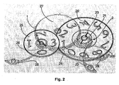
- the figure 2 represents an elevational view of the wheels represented on the figure 1a when implemented in a date display mechanism of a large date type
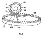
- FIG. 3 is an elevational view of a driving wheel and driven wheel according to a second preferred embodiment of the present invention.
- the figures 1a , 1b and 1 C represent a schematic view of a preferred embodiment of a driving wheel 1 and a driven wheel 2, or pinion, engaged with each other, intended to equip a movement for a timepiece incorporating a date display of the large date type, at three successive times, during operation.
- the driving wheel 1 comprises a drive sector, having an epicycloid-like toothing of fifty-nine identical teeth 100, and a non-toothed positioning sector 101 extending over a width corresponding to three teeth 100.
- the positioning sector 101 has a constant level with respect to the bottom of the toothing substantially corresponding to the height of the foot of the teeth 100. More specifically, the free portion 102 of the positioning sector has substantially the shape of an arc whose center is coincident with that of the wheel 1.
- the driving wheel 1 comprises a central opening 3 intended to cooperate with a shaft or tenon (not shown) to ensure the maintenance and radial guidance.
- the driven wheel, or pinion, 2 comprises a toothing having twenty teeth 200, two first teeth 201 and 202 are truncated at their respective heads. Second and third teeth, 203 and 204, are also truncated more significantly than the first teeth 201 and 202, their free portions being substantially rectilinear, by way of non-limiting example.
- the driven wheel 2 comprises a central opening 5 intended to cooperate with a shaft or tenon (not shown) to ensure the maintenance and radial guidance.
- a hole 6 is provided in the driven wheel, away from its central opening 5, which can be used to ensure its relative angular positioning with respect to a constituent element of the date display mechanism.
- the free portions 210 and 220 of the first truncated teeth 201 and 202 have curved shapes special. Indeed, these free portions are preferably shaped so as to substantially match the shape of the free portion 102 of the positioning sector 101.
- the positioning sector 101 moves opposite the driven wheel 2 without coming into contact with the latter which is not driven.
- the driving of the driven wheel 2 resumes when the tooth 100 situated immediately after the positioning sector 101 comes into contact with the first tooth 202 of the driven wheel, after having passed opposite the tooth 204 without having interacted with it.
- the portions of the driven wheel capable of colliding with the driving wheel 1 have a shape that makes it possible to limit the risks of damage compared to a conventional toothing with which the shocks are located at the level of the tooth tips, particularly fragile.
- the driving wheel 1 which has fifty nine teeth is intended to be driven by a wheel thirty-one teeth advancing one step per day.
- the driving wheel 1 takes a pitch of two teeth 100.
- a step of the driven wheel 2 corresponds to an angular displacement of 200 teeth.
- the second and third teeth 203 and 204 are truncated to be clear of the bearing surface of the driving gear 1, when the teeth 201 and 202 are arranged opposite the latter.
- the last tooth 100 of the driving wheel, adjacent to the toothed sector 101, has moved in the anti-clockwise direction of this wheel, starting from the vicinity of the truncated tooth 201, passing in front of the second truncated tooth 203 without driving it.
- the toothed sector 101 has moved in front of the first truncated teeth 201 and 202 without coming into contact with them until the first tooth 100 of the driving sector of the driving wheel 1 comes into contact with it.
- the first truncated tooth 202 as shown on the figure 1 at. This latter operation takes place without rotation of the driven wheel, because of the truncation formed on the third tooth 204 so that it is located out of reach of the toothing of the driving wheel.
- the driven wheel 2 is secured in rotation, from the point of view of a possible impact that would tend to rotate it.
- the first tooth 100 of the sector drive exerts a force on the first truncated tooth 202 causing the driven wheel 2 to rotate in a clockwise direction, as shown in FIG. figure 1 b.
- the rotation of the driving wheel causes a displacement of the recess 103 relative to the driven wheel, which frees the passage, in rotation, for the first truncated tooth 201.
- the third truncated tooth 204 is then positioned between the first and second teeth 100 of the drive sector, as shown in FIG. figure 1c before being driven by the second of these teeth 100 and that the wheels 1 and 2 mesh in a conventional manner with their teeth 100 and 200.
- the truncated teeth 201 to 204 exhibit a sufficient height to allow their normal training by the teeth 100.
- the level of the positioning sector, relative to the bottom of the teeth of the driving wheel, is such that the operation of the gear can be blocked if the positioning sector is located next to teeth 200 at one time or another cycles of rotation of the wheels 1 and 2.
- the respective teeth of the driving and driven wheels are such that, when the toothed sector 101 of the drive wheel is arranged facing the driven wheel, the first truncated teeth 201 and 202 of the latter face him .
- the period of rotation of the driving wheel is equal to, or is a multiple of, the period of rotation of the driven wheel.
- the gearing being intended to be implemented in a date indication mechanism such as that shown in FIG. figure 2 .
- the driven wheel is mounted coaxially and secured to a disk 20 bearing the numbers from 0 to 9, defining ten steps for the rotational movement of the disk and, provided to display the unit of the value of the date.
- the driven wheel 2 is furthermore integral with a star 21 which is coaxial with it and on which the end of a jumper 22 ensures the stability of certain predefined angular positions of the disc 20.
- the latter bearing ten digits, he must perform a complete turn on himself in ten steps.
- the star 21 comprises, for this reason, ten teeth between which it is expected that the end of the jumper comes to be housed to stabilize the ten angular positions thus defined.
- the driven wheel 2 must have a number of teeth 200 which is a multiple of ten for a number of whole steps of the driven wheel to correspond to a whole number of steps of the disc 20.
- the disc 20 has a slot 23 for effecting a visual angular indexing on the angular position of the star 21 or the driven wheel 2.
- This indexing mark takes the form of a slot also makes it possible to use a tool adapted to adjust the angular position of the disc 20 by acting directly at the mark.
- the driving wheel 1 is mounted coaxially and secured to a wheel of thirty-one teeth 24, or thirty-one wheel, intended to be driven by a clockwork finishing work train, by the intermediate of a clockwork.
- the wheel of thirty-one makes a complete turn on itself in thirty-one days, advancing one step per day, usually at the end of the day. Because of its connection with the thirty-one wheel, the driving wheel also turns on itself in thirty-one days.
- the driving sector of the driving wheel 1 has fifty nine teeth. This number indeed makes it possible to fulfill the condition, stated above, concerning the necessary multiplicity of the period of the driving wheel 1 relative to that of the driven wheel 2.
- the driven wheel 2 is not driven by the driving wheel 1 during the passages of the thirty-first day of a given month to the first of the following month, due to the displacement without drive of the positioning sector facing the teeth of the driven wheel.
- the date indication mechanism comprises a second disk 25 indicating the value of the ten days of the date and carrying for this purpose the numbers from 0 to 3.
- a pinion 26 with eight teeth is mounted coaxially and secured to the disk 25 to ensure his training.
- the pinion is arranged to mesh with a tens wheel 27 mounted coaxial and integral with the thirty-one wheel 24.
- the tens drive wheel 27 has four teeth spaced so as to cause a rotation of a step two teeth of the disk 25 during the changes of ten of the date value, similarly to what is described in the prior art.
- a second jumper 28 acts on the pinion 26, while a third jumper 29 acts on the thirty-one wheel 24, to ensure the positioning of their respective stable angular positions.
- the entire mechanism that has just been described is intended to be mounted on a watch movement platen or on a complication module, in a conventional manner.
- the figure 3 represents, in a perspective view, a second preferred embodiment of the present invention.
- the driving sector of the driving wheel 31 has a tooth-like to edge, that is to say located outside the plane of the wheel board.
- the operating principle of this device is identical to that described in relation to the figures 1a , 1b and 1 C .
- the positioning sector 32, toothless, of the driving wheel 31 has a free surface 33 situated at a constant intermediate level with reference to the height of the toothing, as well as in the first embodiment.
- this free surface 33 is flat, insofar as the bottom of the teeth of the drive sector describes a ring contained in a plane parallel to the plane of the wheel plank, while it described a ribbon in the previous mode .
- the first truncated teeth 41 and 42 of the driven wheel 40 have planar free portions 410 and 420 so as to conform to the shape of the positioning sector 32 when it is arranged opposite them.
- the driven wheel 40 includes second and third teeth 43 and 44 truncated to a degree allowing them to be located out of reach of the teeth of the driving wheel when the first and second teeth truncated 41 and 42 are positioned opposite the driving wheel.
- the driving wheel comprises a plurality of drive sectors separated from one another by a plurality of positioning sectors, without departing from the scope of the present invention.
- wheel is to be interpreted in the broad sense.
- at least one of the wheels may take the form of a pinion or a ring gear.
- the driving wheel is a ring gear with internal teeth, the driven wheel then being located inside the driving wheel.
- the invention is not limited to the number of teeth contributing to the gearing of the two wheels and is applicable to a gear in which one, two or more teeth of each of the wheels are involved in the transmission of the movement. .
- the skilled person will not encounter any particular difficulty to adapt the number of truncated teeth on each wheel, and the shape of their truncations. More specifically, the latter may for example be made in such a way that the free portions 210 and 220 of the teeth 201, 202 are flat.
- the relative heights of the toothing and the toothed sector have also been mentioned as non-limiting indicative and may be modified without departing from the scope of the present invention.
- additional truncated teeth may be omitted depending on the number of teeth contributing to the gearing, the respective dimensions of the two wheels, or the spacing provided between the wheels according to their respective dimensions, therefore their penetration.
Abstract
Description
La présente invention se rapporte au domaine de l'horlogerie. Elle concerne, plus particulièrement, un engrenage destiné à être mis en oeuvre dans un mouvement pour pièce d'horlogerie, du type comportant une roue menante et une roue menée dentées susceptibles d'engrener l'une avec l'autre par leurs dentures respectives. L'une de ces deux roues peut éventuellement prendre la forme d'un pignon. La roue menante comporte au moins un premier secteur denté, d'entraînement, définissant sa denture et au moins un deuxième secteur non denté, de positionnement, agencé à un niveau constant intermédiaire en référence à la hauteur de la denture.The present invention relates to the field of watchmaking. It relates, more particularly, to a gear intended to be implemented in a movement for a timepiece, of the type comprising a driving wheel and a toothed gear wheel capable of meshing with each other by their respective teeth. One of these two wheels can possibly take the form of a pinion. The driving wheel comprises at least a first toothed sector, driving, defining its teeth and at least a second non-toothed positioning sector, arranged at a constant intermediate level with reference to the height of the toothing.
Dans un mode de réalisation préféré de l'invention, la pièce d'horlogerie correspondante est du type comportant un mécanisme d'affichage d'une grande date, c'est-à-dire comprenant des moyens respectifs d'affichage des unités et des dizaines de quantième séparés.In a preferred embodiment of the invention, the corresponding timepiece is of the type comprising a mechanism for displaying a large date, that is to say comprising respective means for displaying the units and dozens of separate dates.
De tels mécanismes sont bien connus de l'état de la technique, comme par exemple du brevet
La première roue comporte trente et une dents et est entraînée à raison d'une dent par jour.The first wheel has thirty-one teeth and is driven at the rate of one tooth per day.
La deuxième roue comporte trente dents de même longueur et une dent présentant une troncature s'étendant jusqu'au fond de la denture pour définir un secteur non denté, de longueur correspondant à une dent. Cette roue engrène avec un pignon comprenant dix dents et solidaire d'un disque portant les chiffres de 0 à 9. Ces différents constituants du mécanisme sont assemblés de telle manière que, lorsque le quantième affiché passe du trente et un d'un mois au premier du mois suivant, le disque d'affichage des unités n'est pas entraîné, du fait que le secteur non denté de la deuxième roue se déplace en regard du pignon correspondant.The second wheel has thirty teeth of the same length and a tooth having a truncation extending to the bottom of the toothing to define an undirected sector, of length corresponding to a tooth. This wheel meshes with a pinion comprising ten teeth and secured to a disc bearing the numbers from 0 to 9. These different components of the mechanism are assembled in such a way that, when the displayed date changes from thirty-one to one month to the first the following month, the display disc units is not driven, because the toothed sector of the second wheel moves opposite the corresponding gear.
Ce mécanisme présente toutefois un inconvénient en ce qu'en cas de choc violent, lorsque le secteur non denté fait face au pignon, ce dernier est susceptible de tourner librement et ce, malgré la présence typique d'un sautoir permettant de définir ses positions angulaires stables.However, this mechanism has the disadvantage that, in the event of a violent impact, when the toothed sector faces the pinion, the pinion is able to turn freely, despite the typical presence of a jumper to define its angular positions. stable.
Une solution technique permettant de supprimer complètement le risque de sauts intempestifs du pignon des unités est également connue de l'état de la technique. Cette solution consiste à prévoir une hauteur du secteur non denté, intermédiaire en référence à la hauteur de la denture et, suffisante pour empêcher la rotation du pignon des unités d'un pas complet, un sautoir assurant le retour du pignon dans sa position stable après le choc. En effet, au moment du choc, lorsque le pignon tourne sur lui-même, une de ses dents entre en collision avec le secteur non denté de la roue d'entraînement, par sa pointe, pour limiter sa rotation.A technical solution to completely eliminate the risk of inadvertent jumping gear units is also known from the state of the art. This solution consists in providing a height of the toothed sector, intermediate with reference to the height of the toothing and, sufficient to prevent the rotation of the gear of the units of a complete step, a jumper ensuring the return of the pinion in its stable position after shock. Indeed, at the moment of impact, when the pinion rotates on itself, one of its teeth collides with the toothed sector of the drive wheel, by its tip, to limit its rotation.
Une telle solution technique, bien qu'efficace, présente un inconvénient important directement lié à la collision mentionnée ci-dessus, qui peut conduire, après des chocs successifs, à une déformation de l'une ou de plusieurs des dents de la roue menée, ou pignon, voire à leur rupture. Bien entendu, dans une telle éventualité, le mécanisme d'affichage de la grande date serait mis hors service et nécessiterait un remplacement du pignon endommagé par un horloger. En outre, si l'utilisateur tarde à déceler le disfonctionnement de l'affichage, dans le cas où l'une au moins des dents du pignon est cassée, des fragments de cette dernière pourraient endommager d'autres parties du mouvement horloger.Such a technical solution, although effective, has a significant disadvantage directly related to the collision mentioned above, which can lead, after successive shocks, to a deformation of one or more teeth of the driven wheel, or pinion, or even break. Of course, in such a case, the mechanism of display of the big date would be put out of service and would require a replacement of the pinion damaged by a watchmaker. In addition, if the user is slow to detect the malfunction of the display, in the case where at least one of the teeth of the pinion is broken, fragments of the latter could damage other parts of the watch movement.
Par ailleurs, on connaît également, par exemple du document
La présente invention a pour but principal d'améliorer la fiabilité et la longévité des engrenages de l'art antérieur, en proposant une solution technique permettant d'éviter les sauts intempestifs des organes d'affichage en cas de choc, tout en améliorant la résistance mécanique de la denture de la roue menée impliquée.The main object of the present invention is to improve the reliability and longevity of the gears of the prior art, by proposing a technical solution making it possible to avoid accidental jumps of the display members in the event of impact, while improving the resistance mechanical gear wheel gearing involved.
A cet effet, l'invention concerne un tel engrenage, caractérisé par le fait que la roue menée comprend au moins une première dent tronquée pour présenter une forme sensiblement complémentaire de celle du secteur de positionnement lorsqu'elle est disposée en regard de ce dernier. Par ailleurs, l'engrenage est en outre caractérisé par le fait que les dentures respectives des roues menante et menée sont agencées et nombrées de telle manière que, lorsque le secteur non denté est disposé en regard de la roue menée, la première dent tronquée de cette dernière lui fait face.To this end, the invention relates to such a gear, characterized in that the driven wheel comprises at least a first tooth truncated to have a shape substantially complementary to that of the positioning sector when it is arranged opposite the latter. Furthermore, the gearing is further characterized by the fact that the respective teeth of the driving and driven wheels are arranged and numbered in such a way that, when the toothed sector is arranged facing the driven wheel, the first truncated tooth of the latter faces him.
Grâce à ces caractéristiques particulières, la dent tronquée de la roue menée permet une rotation de la roue menante sans que la première ne soit entraînée pendant que le secteur de positionnement se déplace en regard de cette dernière. En outre, le fait que la portion libre de la dent tronquée n'est pas pointue, comme la tête d'une dent conventionnelle, permet de limiter les contraintes mécaniques qu'elle est susceptible de subir en cas de choc et donc les risques de dommages.Thanks to these particular characteristics, the truncated tooth of the driven wheel allows rotation of the driving wheel without the first being driven while the positioning sector moves opposite the latter. In addition, the fact that the free portion of the truncated tooth is not pointed, like the head of a conventional tooth, makes it possible to limit the mechanical stresses it is likely to undergo in the event of an impact and therefore the risks of damage.
Dans un mode de réalisation préféré, un engrenage de ce type est mis en oeuvre pour réaliser l'affichage d'un quantième du type grande date, plus précisément, de l'affichage de la valeur de l'unité de ce quantième. A cet effet, la roue menée comporte un multiple m de dix dents, dont m premières dents tronquées. La roue menante, ou roue des unités, présente un nombre de dents égal à trente-et-une fois le multiple m moins (m+une) dents, soit 31 m - (m+1), la périphérie de la roue correspondant à la longueur d'une denture de 31 m dents.In a preferred embodiment, a gear of this type is used to display a date of the big date type, more specifically, the display of the value of the unit of that date. For this purpose, the driven wheel comprises a multiple m of ten teeth, including m first truncated teeth. The driving wheel, or wheel units, has a number of teeth equal to thirty-one times the multiple m minus (m + one) teeth, or 31 m - (m + 1), the periphery of the wheel corresponding to the length of a toothing of 31 m teeth.
Préférablement, le multiple m est pris égal à deux, ce qui correspond à cinquante neuf dents pour la roue des unités, le secteur non denté présentant une longueur correspondant à trois dents, et vingt pour la roue menée, dont deux dents tronquées pour présenter des surfaces libres de formes respectives sensiblement complémentaires de celle du secteur de positionnement lorsqu'elles sont disposées en regard de ce dernier.Preferably, the multiple m is taken equal to two, which corresponds to fifty nine teeth for the unit wheel, the toothless sector having a length corresponding to three teeth, and twenty for the driven wheel, including two teeth truncated to present teeth. free surfaces of respective shapes substantially complementary to that of the positioning sector when they are arranged opposite the latter.
La présente invention concerne également un mouvement horloger dans lequel un tel engrenage est mis en oeuvre, ainsi qu'une roue répondant aux caractéristiques de la roue menée énoncées ci-dessus.The present invention also relates to a watch movement in which such a gear is implemented, as well as a wheel meeting the characteristics of the driven wheel set out above.
D'autres caractéristiques et avantages de l'invention apparaîtront plus clairement à la lecture de la description détaillée qui suit, faite en référence aux dessins annexés présentés à titre d'exemples non limitatifs et dans lesquels:Other features and advantages of the invention will emerge more clearly on reading the detailed description which follows, made with reference to the appended drawings presented by way of non-limiting examples and in which:
- la
- les
- la
- la
Les
La roue menante 1 comporte un secteur d'entraînement, présentant une denture de type épicycloïdale de cinquante neuf dents 100 identiques, et un secteur non denté, de positionnement, 101 s'étendant sur une largeur correspondant à trois dents 100. Le secteur de positionnement 101 présente un niveau constant par rapport au fond de la denture correspondant sensiblement à la hauteur du pied des dents 100. Plus précisément, la portion libre 102 du secteur de positionnement présente sensiblement la forme d'un arc de cercle dont le centre est confondu avec celui de la roue 1.The driving wheel 1 comprises a drive sector, having an epicycloid-like toothing of fifty-nine
La roue menante 1 comporte une ouverture centrale 3 destinée à coopérer avec un arbre ou un tenon (non représenté) permettant d'en assurer le maintien et le guidage radial.The driving wheel 1 comprises a
En outre, une pluralité de trous 4 est également prévu dans la roue menante 1, notamment pour assurer le positionnement et la fixation de la roue menante sur une roue à trente et une dents conventionnelle, tel que cela sera exposé en relation avec la description détaillée de la
La roue menée 2 comporte une ouverture centrale 5 destinée à coopérer avec un arbre ou un tenon (non représenté) permettant d'en assurer le maintien et le guidage radial.The driven
En outre, un trou 6 est prévu dans la roue menée, à distance de son ouverture centrale 5, qui peut être mis à profit pour assurer son positionnement angulaire relatif par rapport à un élément constitutif du mécanisme d'affichage de quantième. On constate, dans la configuration représentée sur la
Ainsi, à partir de cette configuration, si la roue menante 1 tourne dans le sens horaire, le secteur de positionnement 101 se déplace en regard de la roue menée 2 sans entrer en contact avec cette dernière qui n'est donc pas entraînée. L'entraînement de la roue menée 2 reprend lorsque la dent 100 située immédiatement après le secteur de positionnement 101 entre au contact de la première dent 202 de la roue menée, après être passée en regard de la dent 204 sans avoir interagit avec elle.Thus, from this configuration, if the driving wheel 1 rotates clockwise, the
Il ressort, de la
Ces dents présentant des portions libres 210 et 220 de formes complémentaires à celle de la portion libre 102 du secteur de positionnement 101, tout en étant très proches de ce dernier. Le débattement angulaire possible de la roue menée 2 dans cette situation est très faible.These teeth having
En effet, on constate que, dans la configuration représentée sur la
Ces caractéristiques confèrent à l'engrenage, selon le présent mode de réalisation de l'invention, des qualités importantes par rapport aux engrenages de l'art antérieur, en termes de fiabilité et de tenue dans le temps.These characteristics give the gear, according to the present embodiment of the invention, significant qualities compared to the gears of the prior art, in terms of reliability and durability.
On notera que selon le présent mode de réalisation, la roue menante 1 qui comporte cinquante neuf dents est destinée à être entraînée par une roue à trente et une dents avançant d'un pas par jour. Ainsi, à chaque pas de la roue à trente et une dents, communément appelée roue de trente et un, la roue menante 1 effectue un pas de deux dents 100. De même, un pas de la roue menée 2 correspond à un déplacement angulaire de deux dents 200. Pour cette raison, et d'après les dimensions respectives particulières des roues menante 1 et menée 2 de la
Avant de se trouver dans la configuration de la
Comme cela vient d'être exposé ci-dessus, à tout moment de ce déplacement, la roue menée 2 est sécurisée en rotation, du point de vue d'un choc éventuel qui tendrait à la faire tourner.As just stated above, at any moment of this displacement, the driven
Lorsque la roue menante 1 poursuit sa rotation, sous l'effet de sa liaison avec la roue de trente et un, la première dent 100 du secteur d'entraînement exerce une force sur la première dent tronquée 202 provoquant la mise en rotation de la roue menée 2 dans le sens horaire, tel que représenté sur la
La rotation de la roue menante entraîne un déplacement du creux 103 par rapport à la roue menée, ce qui libère le passage, en rotation, pour la première dent tronquée 201.The rotation of the driving wheel causes a displacement of the
La troisième dent tronquée 204 se positionne alors entre les première et deuxième dents 100 du secteur d'entraînement, tel que représenté sur la
Par ailleurs, il apparaît que le niveau du secteur de positionnement, par rapport au fond de la denture de la roue menante, est tel, que le fonctionnement de l'engrenage peut être bloqué si le secteur de positionnement se trouve situé en regard de dents ordinaires 200 à un moment ou à un autre des cycles de rotation des roues 1 et 2.Furthermore, it appears that the level of the positioning sector, relative to the bottom of the teeth of the driving wheel, is such that the operation of the gear can be blocked if the positioning sector is located next to
Ainsi, il est nécessaire que les dentures respectives des roues menante et menée soient telles que, lorsque le secteur non denté 101 de la roue menante est disposé en regard de la roue menée, les premières dents tronquées 201 et 202 de cette dernière lui font face. Autrement dit, il est nécessaire que la période de rotation de la roue menante soit égale à, ou soit un multiple de, la période de rotation de la roue menée.Thus, it is necessary that the respective teeth of the driving and driven wheels are such that, when the
Dans le cas présent, l'engrenage étant destiné à être mis en oeuvre dans un mécanisme d'indication du quantième tel que celui représenté sur la
La roue menée 2 est en outre solidaire d'une étoile 21 qui lui est coaxiale et sur laquelle agit l'extrémité d'un sautoir 22 assurant la stabilité de certaines positions angulaires prédéfinies du disque 20. Ce dernier portant dix chiffres, il doit effectuer un tour complet sur lui-même en dix pas. L'étoile 21 comporte, pour cette raison, dix dents entre lesquelles il est prévu que l'extrémité du sautoir vienne se loger pour stabiliser les dix positions angulaires ainsi définies. La roue menée 2 doit comporter un nombre de dents 200 qui est un multiple de dix pour qu'un nombre de pas entiers de la roue menée corresponde à un nombre de pas entier du disque 20.The driven
Il apparaît également de la
Comme cela a été mentionné précédemment, la roue menante 1 est montée coaxiale et solidaire d'une roue de trente et une dents 24, ou roue de trente et un, destinée à être entraînée par un rouage de finissage de mouvement horloger, par l'intermédiaire d'un rouage de minuterie. La roue de trente et un 24 fait un tour complet sur elle-même en trente et un jours, en avançant d'un pas par jour, généralement en fin de journée. Du fait de sa liaison avec la roue de trente et un, la roue menante effectue également un tour sur elle-même en trente et un jours.As mentioned above, the driving wheel 1 is mounted coaxially and secured to a wheel of thirty-one
Tel que cela ressort mieux de la
Grâce à ces caractéristiques et, en prévoyant un agencement particulier du disque 20, connu de l'état de la technique, l'entraînement de celui-ci intervient trente fois en trente et un jours, la roue menée 2 n'étant pas entraînée par la roue menante 1 lors des passages du trente et unième jour d'un mois donné au premier du mois suivant, du fait du déplacement sans entraînement du secteur de positionnement en regard de la denture de la roue menée.Thanks to these characteristics and, by providing a particular arrangement of the
On constate en outre, sur la
On peut noter qu'un deuxième sautoir 28 agit sur le pignon 26, tandis qu'un troisième sautoir 29 agit sur la roue de trente et un 24, pour assurer le positionnement de leurs positions angulaires stables respectives.It may be noted that a
L'ensemble du mécanisme qui vient d'être décrit est destiné à être monté sur une platine de mouvement horloger ou encore sur un module de complication, de manière conventionnelle.The entire mechanism that has just been described is intended to be mounted on a watch movement platen or on a complication module, in a conventional manner.
La
Dans cette mise en oeuvre, le secteur d'entraînement de la roue menante 31 présente une denture du type en chant, c'est-à-dire située en dehors du plan de la planche de la roue. Le principe de fonctionnement de ce dispositif est identique à celui qui a été décrit en relation avec les
On constate que le secteur de positionnement 32, non denté, de la roue menante 31 présente une surface libre 33 située à un niveau intermédiaire constant en référence à la hauteur de la denture, de même que dans le premier mode de réalisation. Ainsi, cette surface libre 33 est plane, dans la mesure où le fond de la denture du secteur d'entraînement décrit un anneau contenu dans un plan parallèle au plan de la planche de roue, alors qu'il décrivait un ruban dans le mode précédent.It can be seen that the positioning sector 32, toothless, of the driving wheel 31 has a
De ce fait, les premières dents tronquées 41 et 42 de la roue menée 40 présentent des portions libres planes, 410 et 420, de manière à épouser la forme du secteur de positionnement 32 lorsqu'il est disposé en regard de celles-ci. De même que dans le premier mode de réalisation, la roue menée 40 comprend une deuxième et une troisième dents 43 et 44 tronquées dans une mesure leur permettant d'être situées hors de portée de la denture de la roue menante lorsque les première et deuxième dents tronquées 41 et 42 sont positionnées en regard de la roue menante.As a result, the first
La description qui précède s'attache à décrire des modes de réalisation particuliers à titre d'illustration non limitative et, l'invention n'est pas limitée, par exemple, au nombre de dents des roues décrites, à l'application mentionnée à des mécanismes d'affichage de quantième, ou encore à des roues dont les dentures ne décrivent qu'un segment unique. On peut notamment prévoir que la roue menante comprend une pluralité de secteurs d'entraînement séparés les uns des autres par une pluralité de secteurs de positionnement, sans sortir du cadre de la présente invention.The foregoing description attempts to describe particular embodiments by way of non-limiting illustration and the invention is not limited, for example, to the number of teeth of the wheels described, to the application mentioned in FIGS. date display mechanisms, or to wheels whose teeth only describe a single segment. In particular, it is possible to provide that the driving wheel comprises a plurality of drive sectors separated from one another by a plurality of positioning sectors, without departing from the scope of the present invention.
Par ailleurs, la notion de roue est à interpréter au sens large. En particulier, comme cela a été mentionné précédemment, l'une au moins des roues peut prendre la forme d'un pignon, ou encore d'une couronne dentée. En particulier, on pourrait également prévoir que la roue menante est une couronne à denture intérieure, la roue menée étant alors située à l'intérieur de la roue menante.Moreover, the notion of wheel is to be interpreted in the broad sense. In particular, as mentioned above, at least one of the wheels may take the form of a pinion or a ring gear. In particular, it could also be provided that the driving wheel is a ring gear with internal teeth, the driven wheel then being located inside the driving wheel.
De même, l'invention n'est pas limitée au nombre de dents contribuant à l'engrenage des deux roues et est applicable à un engrenage dans lequel une, deux ou plus de trois dents, de chacune des roues interviennent dans la transmission du mouvement. Suivant les cas de figures, l'homme du métier ne rencontrera pas de difficulté particulière pour adapter le nombre de dents tronquées sur chacune des roues, ainsi que la forme de leurs troncatures. Plus précisément, ces dernières peuvent par exemple être réalisées de telle manière que les portions libres 210 et 220 des dents 201, 202 sont planes. Les hauteurs relatives de la denture et du secteur non denté ont également été mentionnées à titre indicatif non limitatif et peuvent être modifiées sans sortir du cadre de la présente invention.Likewise, the invention is not limited to the number of teeth contributing to the gearing of the two wheels and is applicable to a gear in which one, two or more teeth of each of the wheels are involved in the transmission of the movement. . Depending on the case, the skilled person will not encounter any particular difficulty to adapt the number of truncated teeth on each wheel, and the shape of their truncations. More specifically, the latter may for example be made in such a way that the
Il convient également de noter que les dents tronquées supplémentaires peuvent être omises selon le nombre de dents contribuant à l'engrenage, les dimensions respectives des deux roues, ou encore l'écartement prévu entre les roues en fonction de leurs dimensions respectives, donc leur pénétration.It should also be noted that the additional truncated teeth may be omitted depending on the number of teeth contributing to the gearing, the respective dimensions of the two wheels, or the spacing provided between the wheels according to their respective dimensions, therefore their penetration.
Claims (11)
- A gear for a clockwork movement including a toothed driving gear (1, 31) and driven gear (2, 40) able to mesh with one another via their respective toothings, said driving gear including at least one first toothed driving sector, defining said toothing and at least one second non-toothed positioning sector (101, 32), arranged at a constant intermediate level relative to the height of said toothing,
characterized in that said driven gear comprises at least one first truncated tooth (201, 202, 41, 42) to have a free surface (210, 220) with a shape substantially complementary to that of said positioning sector (101, 32) when it is arranged opposite the latter, and in that said respective toothings are arranged and numbered so that, when said non-toothed sector of said driving gear is arranged opposite said driven gear, said first truncated tooth (201, 202, 41, 42) of the latter faces it. - The gear according to claim 1, characterized in that
said driving gear (1, 31) and said driven gear (2, 40) can mesh with each other by at least two teeth (100, 200, 201 to 204) of their respective toothings, when the latter are arranged in predefined respective positions, and
in that said driven gear also comprises a second truncated tooth (203, 43) adjacent to and upstream of said first truncated tooth (201, 202, 41), relative to the direction of rotation of said driven gear, said second tooth being truncated so as to be situated out of reach of the toothing of said driving gear when said first and second truncated teeth are positioned in said predefined position. - The gear according to claim 2, characterized in that said driving gear (1, 31) and said driven gear (2, 40) can mesh with each other by at least three teeth of their respective toothings, when the latter are arranged in predefined respective positions, and
in that said driven gear also comprises a first additional truncated tooth (202, 42) also adjacent to said first truncated tooth (201, 41) and having a free surface (220) with a shape substantially complementary to that of said positioning sector (101, 32) when it is arranged opposite the latter. - The gear according to claim 2 or 3, characterized in that said driven gear comprises a third truncated tooth (204, 44) arranged downstream of that (202, 42) of said other truncated teeth that is situated the furthest downstream, relative to the direction of rotation of said driven gear, said third tooth (204, 44) being truncated so as to be arranged out of reach of the toothing of said driving gear when said first truncated teeth (201, 202, 41, 42) are arranged in said predefined position.
- The gear according to any one of the preceding claims, characterized in that said positioning sector (101) has a free surface, which can be arranged opposite said driven gear, which generally has the shape of a cylinder portion.
- The gear according to any one of claims 1 to 4, characterized in that one of said toothings is a contrate toothing.
- The gear according to claim 6, characterized in that said contrate toothing is that of said driving gear (31), and
in that said positioning sector (32) has a free surface, which can be arranged opposite said driven gear (40), having a generally flat shape. - The gear according to any one of the preceding claims, intended to be implemented in a mechanism for displaying a date, characterized in that the toothing of said driven gear (2, 40) includes a multiple m of ten teeth (200, 201 to 204), while the toothing of said driven gear (1, 31) includes 31 m-(m+1) teeth (100).
- A mechanism for indicating a date of the large date type intended to be driven by a clockwork movement going train, and comprising a gear according to any one of the preceding claims, a mobile organ (20) for indicating the unit of said date driven by said driven gear (2) as well as means (25, 26, 27) for indicating the tens of said date.
- A timepiece movement comprising a going train arranged to drive a mechanism for indicating a date according to claim 9.
- A timepiece comprising a movement according to claim 10 and at least one opening able to make the indication of the date of the major date type visible.
Priority Applications (3)
| Application Number | Priority Date | Filing Date | Title |
|---|---|---|---|
| AT05112645T ATE545070T1 (en) | 2005-12-21 | 2005-12-21 | GEARINGS FOR CLOCK MOVEMENTS, MECHANISM AND CLOCK MOVEMENT COMPRISING SUCH GEARING |
| EP05112645A EP1801667B1 (en) | 2005-12-21 | 2005-12-21 | Gears for timepiece movement, mechanism and timepiece movement including said gears |
| ES05112645T ES2381556T3 (en) | 2005-12-21 | 2005-12-21 | Gear for watch movement, clock movement and movement comprising said gear |
Applications Claiming Priority (1)
| Application Number | Priority Date | Filing Date | Title |
|---|---|---|---|
| EP05112645A EP1801667B1 (en) | 2005-12-21 | 2005-12-21 | Gears for timepiece movement, mechanism and timepiece movement including said gears |
Publications (2)
| Publication Number | Publication Date |
|---|---|
| EP1801667A1 EP1801667A1 (en) | 2007-06-27 |
| EP1801667B1 true EP1801667B1 (en) | 2012-02-08 |
Family
ID=37188879
Family Applications (1)
| Application Number | Title | Priority Date | Filing Date |
|---|---|---|---|
| EP05112645A Not-in-force EP1801667B1 (en) | 2005-12-21 | 2005-12-21 | Gears for timepiece movement, mechanism and timepiece movement including said gears |
Country Status (3)
| Country | Link |
|---|---|
| EP (1) | EP1801667B1 (en) |
| AT (1) | ATE545070T1 (en) |
| ES (1) | ES2381556T3 (en) |
Families Citing this family (1)
| Publication number | Priority date | Publication date | Assignee | Title |
|---|---|---|---|---|
| EP2985660B1 (en) | 2014-08-14 | 2019-05-22 | Montres Tudor S.A. | Timepiece device for displaying a time or time-derived indication |
Family Cites Families (3)
| Publication number | Priority date | Publication date | Assignee | Title |
|---|---|---|---|---|
| CH310559A (en) | 1953-07-03 | 1955-10-31 | Fontainemelon Horlogerie | Calendar timepiece. |
| DE60230011D1 (en) * | 2002-04-02 | 2009-01-08 | Nardin Ulysse Sa | Device with program wheel for the mechanism of a perpetual calendar as well as clock with such mechanism |
| CH697662B1 (en) * | 2004-04-14 | 2009-01-15 | Chopard Manufacture Sa | Mechanism of perpetual or annual calendar. |
-
2005
- 2005-12-21 AT AT05112645T patent/ATE545070T1/en active
- 2005-12-21 EP EP05112645A patent/EP1801667B1/en not_active Not-in-force
- 2005-12-21 ES ES05112645T patent/ES2381556T3/en active Active
Also Published As
| Publication number | Publication date |
|---|---|
| EP1801667A1 (en) | 2007-06-27 |
| ATE545070T1 (en) | 2012-02-15 |
| ES2381556T3 (en) | 2012-05-29 |
Similar Documents
| Publication | Publication Date | Title |
|---|---|---|
| EP3430482B1 (en) | Mechanism for a watch movement | |
| EP0756217A1 (en) | Annual calendar mechanism for timepieces | |
| EP1316859A1 (en) | Method for forming a date mechanism operated by a clockwork | |
| EP3008523B1 (en) | Calendar mechanism for a clock movement | |
| EP1978420B1 (en) | Gear wheel for a timepiece and device for correction of a display mechanism for a timepiece incorporating such a wheel | |
| EP1070996B1 (en) | Timepiece with date display | |
| EP1536299B1 (en) | Calendar mechanism for a watch comprising two superposed date annuli | |
| EP1536300B1 (en) | Calendar mechanism for a watch comprising two superposed date annuli | |
| EP3904964B1 (en) | Device for displaying a time or time-derived indication and device for indexing | |
| EP1801667B1 (en) | Gears for timepiece movement, mechanism and timepiece movement including said gears | |
| CH713209B1 (en) | Display mechanism for timepiece. | |
| EP2096504B1 (en) | Mechanism for displaying dead seconds | |
| EP3786723B1 (en) | Date display mechanism | |
| EP3159752B1 (en) | Programming mobile for clock movement | |
| CH711184B1 (en) | Watch movement comprising a mechanism for rapid correction of the current time. | |
| EP1734419B1 (en) | Timepiece with calendar mechanismus | |
| CH707959B1 (en) | Drive system of a date indicator. | |
| CH707439B1 (en) | Anti-retrograde display mechanism for a timepiece. | |
| WO2012127053A1 (en) | Actuating mechanism for a timepiece movement and corresponding timepiece movement | |
| EP3845973B1 (en) | Timepiece mechanism intended to be driven according to a variable number of pitches | |
| EP3904962B1 (en) | Device for indexing and device for displaying a time or time-derived indication | |
| EP4033306B1 (en) | Annual or perpetual date mechanism | |
| CH689601A5 (en) | Day of the month mechanism for timepiece | |
| EP3629101B1 (en) | Timepiece display mechanism | |
| CH715246A2 (en) | Display device comprising a mobile indicator moving along a predefined path. |
Legal Events
| Date | Code | Title | Description |
|---|---|---|---|
| PUAI | Public reference made under article 153(3) epc to a published international application that has entered the european phase |
Free format text: ORIGINAL CODE: 0009012 |
|
| AK | Designated contracting states |
Kind code of ref document: A1 Designated state(s): AT BE BG CH CY CZ DE DK EE ES FI FR GB GR HU IE IS IT LI LT LU LV MC NL PL PT RO SE SI SK TR |
|
| AX | Request for extension of the european patent |
Extension state: AL BA HR MK YU |
|
| 17P | Request for examination filed |
Effective date: 20071116 |
|
| AKX | Designation fees paid |
Designated state(s): AT BE BG CH CY CZ DE DK EE ES FI FR GB GR HU IE IS IT LI LT LU LV MC NL PL PT RO SE SI SK TR |
|
| 17Q | First examination report despatched |
Effective date: 20110214 |
|
| RTI1 | Title (correction) |
Free format text: GEARS FOR TIMEPIECE MOVEMENT, MECHANISM AND TIMEPIECE MOVEMENT INCLUDING SAID GEARS |
|
| GRAP | Despatch of communication of intention to grant a patent |
Free format text: ORIGINAL CODE: EPIDOSNIGR1 |
|
| RAP1 | Party data changed (applicant data changed or rights of an application transferred) |
Owner name: CHRISTOPHE CLARET S.A. |
|
| GRAS | Grant fee paid |
Free format text: ORIGINAL CODE: EPIDOSNIGR3 |
|
| GRAA | (expected) grant |
Free format text: ORIGINAL CODE: 0009210 |
|
| RAP1 | Party data changed (applicant data changed or rights of an application transferred) |
Owner name: MANUFACTURE CLARET SA |
|
| AK | Designated contracting states |
Kind code of ref document: B1 Designated state(s): AT BE BG CH CY CZ DE DK EE ES FI FR GB GR HU IE IS IT LI LT LU LV MC NL PL PT RO SE SI SK TR |
|
| REG | Reference to a national code |
Ref country code: GB Ref legal event code: FG4D Free format text: NOT ENGLISH |
|
| REG | Reference to a national code |
Ref country code: CH Ref legal event code: EP Ref country code: AT Ref legal event code: REF Ref document number: 545070 Country of ref document: AT Kind code of ref document: T Effective date: 20120215 |
|
| REG | Reference to a national code |
Ref country code: CH Ref legal event code: NV Representative=s name: GLN S.A. |
|
| REG | Reference to a national code |
Ref country code: DE Ref legal event code: R096 Ref document number: 602005032577 Country of ref document: DE Effective date: 20120405 |
|
| REG | Reference to a national code |
Ref country code: ES Ref legal event code: FG2A Ref document number: 2381556 Country of ref document: ES Kind code of ref document: T3 Effective date: 20120529 |
|
| REG | Reference to a national code |
Ref country code: NL Ref legal event code: VDEP Effective date: 20120208 |
|
| LTIE | Lt: invalidation of european patent or patent extension |
Effective date: 20120208 |
|
| PG25 | Lapsed in a contracting state [announced via postgrant information from national office to epo] |
Ref country code: IS Free format text: LAPSE BECAUSE OF FAILURE TO SUBMIT A TRANSLATION OF THE DESCRIPTION OR TO PAY THE FEE WITHIN THE PRESCRIBED TIME-LIMIT Effective date: 20120608 Ref country code: NL Free format text: LAPSE BECAUSE OF FAILURE TO SUBMIT A TRANSLATION OF THE DESCRIPTION OR TO PAY THE FEE WITHIN THE PRESCRIBED TIME-LIMIT Effective date: 20120208 Ref country code: LT Free format text: LAPSE BECAUSE OF FAILURE TO SUBMIT A TRANSLATION OF THE DESCRIPTION OR TO PAY THE FEE WITHIN THE PRESCRIBED TIME-LIMIT Effective date: 20120208 |
|
| REG | Reference to a national code |
Ref country code: IE Ref legal event code: FD4D |
|
| PG25 | Lapsed in a contracting state [announced via postgrant information from national office to epo] |
Ref country code: PT Free format text: LAPSE BECAUSE OF FAILURE TO SUBMIT A TRANSLATION OF THE DESCRIPTION OR TO PAY THE FEE WITHIN THE PRESCRIBED TIME-LIMIT Effective date: 20120608 Ref country code: FI Free format text: LAPSE BECAUSE OF FAILURE TO SUBMIT A TRANSLATION OF THE DESCRIPTION OR TO PAY THE FEE WITHIN THE PRESCRIBED TIME-LIMIT Effective date: 20120208 Ref country code: PL Free format text: LAPSE BECAUSE OF FAILURE TO SUBMIT A TRANSLATION OF THE DESCRIPTION OR TO PAY THE FEE WITHIN THE PRESCRIBED TIME-LIMIT Effective date: 20120208 Ref country code: GR Free format text: LAPSE BECAUSE OF FAILURE TO SUBMIT A TRANSLATION OF THE DESCRIPTION OR TO PAY THE FEE WITHIN THE PRESCRIBED TIME-LIMIT Effective date: 20120509 Ref country code: LV Free format text: LAPSE BECAUSE OF FAILURE TO SUBMIT A TRANSLATION OF THE DESCRIPTION OR TO PAY THE FEE WITHIN THE PRESCRIBED TIME-LIMIT Effective date: 20120208 |
|
| REG | Reference to a national code |
Ref country code: AT Ref legal event code: MK05 Ref document number: 545070 Country of ref document: AT Kind code of ref document: T Effective date: 20120208 |
|
| PG25 | Lapsed in a contracting state [announced via postgrant information from national office to epo] |
Ref country code: CY Free format text: LAPSE BECAUSE OF FAILURE TO SUBMIT A TRANSLATION OF THE DESCRIPTION OR TO PAY THE FEE WITHIN THE PRESCRIBED TIME-LIMIT Effective date: 20120208 |
|
| PG25 | Lapsed in a contracting state [announced via postgrant information from national office to epo] |
Ref country code: SI Free format text: LAPSE BECAUSE OF FAILURE TO SUBMIT A TRANSLATION OF THE DESCRIPTION OR TO PAY THE FEE WITHIN THE PRESCRIBED TIME-LIMIT Effective date: 20120208 Ref country code: IE Free format text: LAPSE BECAUSE OF FAILURE TO SUBMIT A TRANSLATION OF THE DESCRIPTION OR TO PAY THE FEE WITHIN THE PRESCRIBED TIME-LIMIT Effective date: 20120208 Ref country code: CZ Free format text: LAPSE BECAUSE OF FAILURE TO SUBMIT A TRANSLATION OF THE DESCRIPTION OR TO PAY THE FEE WITHIN THE PRESCRIBED TIME-LIMIT Effective date: 20120208 Ref country code: EE Free format text: LAPSE BECAUSE OF FAILURE TO SUBMIT A TRANSLATION OF THE DESCRIPTION OR TO PAY THE FEE WITHIN THE PRESCRIBED TIME-LIMIT Effective date: 20120208 Ref country code: SE Free format text: LAPSE BECAUSE OF FAILURE TO SUBMIT A TRANSLATION OF THE DESCRIPTION OR TO PAY THE FEE WITHIN THE PRESCRIBED TIME-LIMIT Effective date: 20120208 Ref country code: DK Free format text: LAPSE BECAUSE OF FAILURE TO SUBMIT A TRANSLATION OF THE DESCRIPTION OR TO PAY THE FEE WITHIN THE PRESCRIBED TIME-LIMIT Effective date: 20120208 Ref country code: RO Free format text: LAPSE BECAUSE OF FAILURE TO SUBMIT A TRANSLATION OF THE DESCRIPTION OR TO PAY THE FEE WITHIN THE PRESCRIBED TIME-LIMIT Effective date: 20120208 |
|
| PG25 | Lapsed in a contracting state [announced via postgrant information from national office to epo] |
Ref country code: SK Free format text: LAPSE BECAUSE OF FAILURE TO SUBMIT A TRANSLATION OF THE DESCRIPTION OR TO PAY THE FEE WITHIN THE PRESCRIBED TIME-LIMIT Effective date: 20120208 |
|
| PLBE | No opposition filed within time limit |
Free format text: ORIGINAL CODE: 0009261 |
|
| STAA | Information on the status of an ep patent application or granted ep patent |
Free format text: STATUS: NO OPPOSITION FILED WITHIN TIME LIMIT |
|
| REG | Reference to a national code |
Ref country code: CH Ref legal event code: PCAR Free format text: NEW ADDRESS: AVENUE EDOUARD-DUBOIS 20, 2000 NEUCHATEL (CH) |
|
| 26N | No opposition filed |
Effective date: 20121109 |
|
| PG25 | Lapsed in a contracting state [announced via postgrant information from national office to epo] |
Ref country code: AT Free format text: LAPSE BECAUSE OF FAILURE TO SUBMIT A TRANSLATION OF THE DESCRIPTION OR TO PAY THE FEE WITHIN THE PRESCRIBED TIME-LIMIT Effective date: 20120208 |
|
| REG | Reference to a national code |
Ref country code: DE Ref legal event code: R097 Ref document number: 602005032577 Country of ref document: DE Effective date: 20121109 |
|
| REG | Reference to a national code |
Ref country code: CH Ref legal event code: PUE Owner name: CHRISTOPHE CLARET ENGINEERING S.A., CH Free format text: FORMER OWNER: MANUFACTURE CLARET SA, CH |
|
| REG | Reference to a national code |
Ref country code: DE Ref legal event code: R081 Ref document number: 602005032577 Country of ref document: DE Owner name: CHRISTOPHE CLARET ENGINEERING SA, CH Free format text: FORMER OWNER: MANUFACTURE CLARET SA, LE LOCLE, CH Effective date: 20130425 Ref country code: DE Ref legal event code: R081 Ref document number: 602005032577 Country of ref document: DE Owner name: CHRISTOPHE CLARET ENGINEERING SA, CH Free format text: FORMER OWNER: CHRISTOPHE CLARET SA, LE LOCLE, CH Effective date: 20120210 |
|
| REG | Reference to a national code |
Ref country code: GB Ref legal event code: 732E Free format text: REGISTERED BETWEEN 20130523 AND 20130529 |
|
| REG | Reference to a national code |
Ref country code: FR Ref legal event code: TP Owner name: CHRISTOPHE CLARET ENGINEERING S.A., CH Effective date: 20130527 |
|
| BERE | Be: lapsed |
Owner name: MANUFACTURE CLARET SA Effective date: 20121231 |
|
| PG25 | Lapsed in a contracting state [announced via postgrant information from national office to epo] |
Ref country code: BG Free format text: LAPSE BECAUSE OF FAILURE TO SUBMIT A TRANSLATION OF THE DESCRIPTION OR TO PAY THE FEE WITHIN THE PRESCRIBED TIME-LIMIT Effective date: 20120508 Ref country code: MC Free format text: LAPSE BECAUSE OF NON-PAYMENT OF DUE FEES Effective date: 20121231 |
|
| PG25 | Lapsed in a contracting state [announced via postgrant information from national office to epo] |
Ref country code: BE Free format text: LAPSE BECAUSE OF NON-PAYMENT OF DUE FEES Effective date: 20121231 |
|
| PG25 | Lapsed in a contracting state [announced via postgrant information from national office to epo] |
Ref country code: IT Free format text: LAPSE BECAUSE OF NON-PAYMENT OF DUE FEES Effective date: 20121221 |
|
| PGFP | Annual fee paid to national office [announced via postgrant information from national office to epo] |
Ref country code: GB Payment date: 20131227 Year of fee payment: 9 Ref country code: DE Payment date: 20131230 Year of fee payment: 9 |
|
| PGFP | Annual fee paid to national office [announced via postgrant information from national office to epo] |
Ref country code: FR Payment date: 20131217 Year of fee payment: 9 |
|
| PG25 | Lapsed in a contracting state [announced via postgrant information from national office to epo] |
Ref country code: TR Free format text: LAPSE BECAUSE OF FAILURE TO SUBMIT A TRANSLATION OF THE DESCRIPTION OR TO PAY THE FEE WITHIN THE PRESCRIBED TIME-LIMIT Effective date: 20120208 |
|
| REG | Reference to a national code |
Ref country code: ES Ref legal event code: FD2A Effective date: 20140527 |
|
| PG25 | Lapsed in a contracting state [announced via postgrant information from national office to epo] |
Ref country code: LU Free format text: LAPSE BECAUSE OF NON-PAYMENT OF DUE FEES Effective date: 20121221 Ref country code: ES Free format text: LAPSE BECAUSE OF NON-PAYMENT OF DUE FEES Effective date: 20071222 |
|
| PG25 | Lapsed in a contracting state [announced via postgrant information from national office to epo] |
Ref country code: HU Free format text: LAPSE BECAUSE OF FAILURE TO SUBMIT A TRANSLATION OF THE DESCRIPTION OR TO PAY THE FEE WITHIN THE PRESCRIBED TIME-LIMIT Effective date: 20051221 |
|
| REG | Reference to a national code |
Ref country code: DE Ref legal event code: R119 Ref document number: 602005032577 Country of ref document: DE |
|
| GBPC | Gb: european patent ceased through non-payment of renewal fee |
Effective date: 20141221 |
|
| REG | Reference to a national code |
Ref country code: FR Ref legal event code: ST Effective date: 20150831 |
|
| PG25 | Lapsed in a contracting state [announced via postgrant information from national office to epo] |
Ref country code: GB Free format text: LAPSE BECAUSE OF NON-PAYMENT OF DUE FEES Effective date: 20141221 Ref country code: DE Free format text: LAPSE BECAUSE OF NON-PAYMENT OF DUE FEES Effective date: 20150701 |
|
| PG25 | Lapsed in a contracting state [announced via postgrant information from national office to epo] |
Ref country code: FR Free format text: LAPSE BECAUSE OF NON-PAYMENT OF DUE FEES Effective date: 20141231 |
|
| REG | Reference to a national code |
Ref country code: CH Ref legal event code: PFA Owner name: CHRISTOPHE CLARET ENGINEERING S.A., CH Free format text: FORMER OWNER: CHRISTOPHE CLARET ENGINEERING S.A., CH |
|
| PGFP | Annual fee paid to national office [announced via postgrant information from national office to epo] |
Ref country code: CH Payment date: 20180329 Year of fee payment: 13 |
|
| REG | Reference to a national code |
Ref country code: CH Ref legal event code: NV Representative=s name: BOVARD SA NEUCHATEL CONSEILS EN PROPRIETE INTE, CH |
|
| REG | Reference to a national code |
Ref country code: CH Ref legal event code: PL |
|
| PG25 | Lapsed in a contracting state [announced via postgrant information from national office to epo] |
Ref country code: CH Free format text: LAPSE BECAUSE OF NON-PAYMENT OF DUE FEES Effective date: 20181231 Ref country code: LI Free format text: LAPSE BECAUSE OF NON-PAYMENT OF DUE FEES Effective date: 20181231 |