EP1801369A1 - Saugrohr-Zylinderkopfanordnung - Google Patents
Saugrohr-Zylinderkopfanordnung Download PDFInfo
- Publication number
- EP1801369A1 EP1801369A1 EP06026221A EP06026221A EP1801369A1 EP 1801369 A1 EP1801369 A1 EP 1801369A1 EP 06026221 A EP06026221 A EP 06026221A EP 06026221 A EP06026221 A EP 06026221A EP 1801369 A1 EP1801369 A1 EP 1801369A1
- Authority
- EP
- European Patent Office
- Prior art keywords
- intake manifold
- positioning
- cylinder head
- head assembly
- cross
- Prior art date
- Legal status (The legal status is an assumption and is not a legal conclusion. Google has not performed a legal analysis and makes no representation as to the accuracy of the status listed.)
- Granted
Links
- 239000012530 fluid Substances 0.000 claims description 10
- 238000002485 combustion reaction Methods 0.000 claims description 9
- 239000007789 gas Substances 0.000 description 26
- 230000001771 impaired effect Effects 0.000 description 2
- 238000004519 manufacturing process Methods 0.000 description 2
- 238000009423 ventilation Methods 0.000 description 2
- 230000005540 biological transmission Effects 0.000 description 1
- 230000015572 biosynthetic process Effects 0.000 description 1
- 239000000567 combustion gas Substances 0.000 description 1
- 150000001875 compounds Chemical class 0.000 description 1
- 230000001419 dependent effect Effects 0.000 description 1
- 238000011161 development Methods 0.000 description 1
- 230000018109 developmental process Effects 0.000 description 1
- 230000003993 interaction Effects 0.000 description 1
- 238000007789 sealing Methods 0.000 description 1
- 238000013022 venting Methods 0.000 description 1
Images

Classifications
-
- F—MECHANICAL ENGINEERING; LIGHTING; HEATING; WEAPONS; BLASTING
- F01—MACHINES OR ENGINES IN GENERAL; ENGINE PLANTS IN GENERAL; STEAM ENGINES
- F01M—LUBRICATING OF MACHINES OR ENGINES IN GENERAL; LUBRICATING INTERNAL COMBUSTION ENGINES; CRANKCASE VENTILATING
- F01M13/00—Crankcase ventilating or breathing
- F01M13/02—Crankcase ventilating or breathing by means of additional source of positive or negative pressure
- F01M13/021—Crankcase ventilating or breathing by means of additional source of positive or negative pressure of negative pressure
- F01M13/022—Crankcase ventilating or breathing by means of additional source of positive or negative pressure of negative pressure using engine inlet suction
-
- F—MECHANICAL ENGINEERING; LIGHTING; HEATING; WEAPONS; BLASTING
- F02—COMBUSTION ENGINES; HOT-GAS OR COMBUSTION-PRODUCT ENGINE PLANTS
- F02M—SUPPLYING COMBUSTION ENGINES IN GENERAL WITH COMBUSTIBLE MIXTURES OR CONSTITUENTS THEREOF
- F02M35/00—Combustion-air cleaners, air intakes, intake silencers, or induction systems specially adapted for, or arranged on, internal-combustion engines
- F02M35/10—Air intakes; Induction systems
- F02M35/10006—Air intakes; Induction systems characterised by the position of elements of the air intake system in direction of the air intake flow, i.e. between ambient air inlet and supply to the combustion chamber
- F02M35/10078—Connections of intake systems to the engine
-
- F—MECHANICAL ENGINEERING; LIGHTING; HEATING; WEAPONS; BLASTING
- F02—COMBUSTION ENGINES; HOT-GAS OR COMBUSTION-PRODUCT ENGINE PLANTS
- F02M—SUPPLYING COMBUSTION ENGINES IN GENERAL WITH COMBUSTIBLE MIXTURES OR CONSTITUENTS THEREOF
- F02M35/00—Combustion-air cleaners, air intakes, intake silencers, or induction systems specially adapted for, or arranged on, internal-combustion engines
- F02M35/10—Air intakes; Induction systems
- F02M35/10209—Fluid connections to the air intake system; their arrangement of pipes, valves or the like
- F02M35/10222—Exhaust gas recirculation [EGR]; Positive crankcase ventilation [PCV]; Additional air admission, lubricant or fuel vapour admission
-
- F—MECHANICAL ENGINEERING; LIGHTING; HEATING; WEAPONS; BLASTING
- F02—COMBUSTION ENGINES; HOT-GAS OR COMBUSTION-PRODUCT ENGINE PLANTS
- F02M—SUPPLYING COMBUSTION ENGINES IN GENERAL WITH COMBUSTIBLE MIXTURES OR CONSTITUENTS THEREOF
- F02M35/00—Combustion-air cleaners, air intakes, intake silencers, or induction systems specially adapted for, or arranged on, internal-combustion engines
- F02M35/10—Air intakes; Induction systems
- F02M35/104—Intake manifolds
- F02M35/112—Intake manifolds for engines with cylinders all in one line
Definitions
- the present invention relates to an intake manifold cylinder head assembly according to the preamble of claim 1.
- Such arrangements with intake manifold and cylinder head are used for venting of the crankcase of internal combustion engines.
- gases which arise in the combustion chambers of the engine and pass the piston rings in the crankcase, forwarded for further use.
- gases are also called “blow-by gases”.
- These gases can be sucked off by means of a suction line, for example in the form of a suction pipe or an intake pipe, in order to supply these again to the internal combustion engine.
- a suction pipe which is arranged on the internal combustion engine, fluidly connected to a gas return line of a cylinder head. It is particularly important that in order to avoid power failures, the intake manifold is optimally arranged on the internal combustion engine or the internal combustion engine and so a dense interface between the cylinder head and intake manifold for sealing transmission of the gas is created.
- a generic crankcase ventilation system is, for example, the DE 10 2004 012 160 A1 refer to.
- the cylinder head has a flange or inlet flange, in which at least two bores are formed, in which two positioning elements of the suction pipe engage. Furthermore, the flange for the gas inlet from the crankcase ventilation via the cylinder head and the gas return line on an additional third hole. This represents a connecting channel between the gas return line of the cylinder head and the suction pipe, that is, the third bore connects as a channel or channel portion, the gas return line to the suction pipe.
- the third hole formed as a channel is to be formed so that it fluidly connects the gas return line and the suction tube, which requires a high degree of precision.
- the invention includes the technical teaching that in an intake manifold cylinder head assembly for an internal combustion engine of a motor vehicle with at least one intake manifold having a Saugrohrvorraum, which is arranged over a Flange comprising a PositionierausEnglishept to a corresponding with the recesses positioning cylinder head, which comprises a gas recirculation line , which is a connection between the crankshaft space and the suction tube produces, wherein the compound extends over one or more of the positioning.
- the intake manifold cylinder head assembly comprises a cylinder head and a Saugrohrvoriques with at least one suction pipe, which is preferably designed as Saugrohrverteiler.
- the cylinder head has a flange on the side. Positioning recesses and further recesses for further fastening and / or fixing of the intake manifold device to the cylinder head are provided on this flange.
- the gas recirculation line (s) open into the flange, to be more precise its newly formed and inclined surface.
- At least one of the positioning recesses is designed for the fluidic connection in the manner of a blind hole. This is easy to manufacture and, in addition to the possibility of using standard connection or positioning elements such as pins and the like, offers the possibility of exactly maintaining a predetermined depth of the positioning recess. Thus, the positioning recess can be precisely tuned to running in the cylinder head channels or lines.
- the gas return line opens into the positioning recess near the bottom region of the blind-hole-shaped positioning recess.
- the floor area is the area in which the positioning recess, which is formed starting from an outside, ends.
- the positioning recess Through the mouth of the gas recirculation line in the bottom region, a large part of the positioning recess can cooperate with a positioning element and only a small area, which is less effective for the positioning and / or fastening of the positioning element or for the interaction of the positioning element and the positioning recess, can be used for the passage be used of the fluid or flowing medium.
- the blind hole-shaped design of the positioning recess and the opening in the bottom region of the positioning recess results in optimum utilization of the positioning recess and a compact design.
- the positioning elements are designed in a plug-like manner to cooperate with the corresponding positioning recesses according to a plug-socket principle. Due to the plug-like design, the fitter receives feedback when the positioning element enters the positioning recess and therefore knows whether the intake manifold device and the cylinder head are correctly positioned.
- a first positioning element is arranged in an inlet region of the suction tube.
- the inlet region is to be understood as the mouth region of the suction pipe or of the inlet pipe branching off from the suction pipe in the outlet region, that is to say the region in which the intake pipe and cylinder head are connected to one another or else the interface region.
- the positioning element is designed so that it undergoes sufficient stability and support.
- the inlet portion is formed by an inlet channel leading to the suction pipe.
- the positioning element does not have to be formed directly in the suction tube but can also be arranged in a kind of "secondary arm" of the suction tube, that is to say a branching inlet channel, whereby other flow conditions may be formed here.
- the first positioning element has a smaller cross-section than a corresponding first positioning recess and / or the inlet region, so that a fluid can flow past the first positioning element into the suction tube.
- the positioning element is arranged in a recess of the inlet region in order to ensure sufficient clearance for the passage of the fluid.
- the cross section is to be interpreted so that on the one hand, the flow is not or only minimally impaired and on the other hand, the stability of the positioning is not impaired.
- the first positioning element prefferably be shaped as an elongated part, preferably in the manner of a sword.
- the positioning has an optimally cooperating with the positioning recess outstanding part. Due to the design as a sword, a precise positioning can be realized with a small cross-sectional area, so that sufficient fluid can flow at the cross-section through the cross-sectional opening of the inlet area.
- the cross section of the second positioning element is selected from the group consisting of round, rectangular, square, oval, polygonal, cross-shaped or profile cross sections. Basically any one can be Use cross section. However, the above-mentioned cross-sections have an optimum positioning property with correspondingly optimized production outlay.
- the second positioning element has substantially the same cross-section as the corresponding second positioning recess in order to realize a form-fitting plug connection.
- the second positioning element is the positioning element which is not arranged in the inlet region of the suction tube.
- Fig. 1 shows a perspective view of a cylinder head 1 according to the invention an intake manifold cylinder head assembly according to the invention.
- the cylinder head 1 has laterally a flange 2 with a flat surface, which is formed inclined for better connection to other devices. From the surface In the direction of the cylinder head, the gas recirculation lines 3 (see also FIG. 3) and the positioning recesses 4 run differently on.
- the flange 2 has two positioning recesses 4, wherein a first positioning recess 4afluidisch is connected to at least one gas return line 3 and the second positioning recess 4b is designed only for receiving a corresponding positioning element. As a result, a medium can flow from the gas return line 3 into / through the first positioning recess 4a.
- the surface of the flange 2 is flat, so as to provide a connection for a Saugrohrvortechnik or more precisely at least one suction tube.
- a Saugrohrvortechnik is shown in Fig. 2.
- FIG. 2 shows a perspective view of a suction pipe device 5, which in the present case is designed as an intake manifold with four intake pipes 6 with at least one branching inlet duct 6a, which are each designed to conduct media.
- the mouths or the mouth cross-sections of the intake manifolds and the suction tubes 6 together with inlet channel 6a are formed corresponding to the surface of the flange in Fig. 1 plan in a plane to be arranged on the also flat flange of the cylinder head of FIG.
- the suction tube device 5 has two positioning elements 7, a first positioning element 7a and a second positioning element 7b.
- the second positioning element 7b is designed as a projection or pin projecting like a plug over the mouth region of the inlet channel 6a, which in the present case has a cross-shaped cross section and is designed for positioning in the second positioning recess 4b.
- the first positioning element 4a is formed in a recess of a suction tube 6, more precisely a section of a suction tube 6 - the inlet channel 6a - and also projects beyond the mouth region, so that this positioning element 7a are inserted into a corresponding positioning recess, here into the first positioning recess can according to a plug-socket principle.
- the first positioning element 7a has a sword-shaped form, i. an approximately elongated, cuboid formation with an approximately rectangular cross-section, wherein the cross-section for optimal passage of a fluid or medium is minimized.
- the first positioning element 7a has a recess running in the longitudinal direction in order to provide the largest possible flow cross-section for a fluid.
- the positioning elements 7 are inserted in the assembly of the intake manifold 5 to the cylinder head in the corresponding positioning recesses of the cylinder head of FIG. An assembled intake manifold cylinder head assembly is shown in FIG.
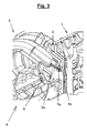
- FIG. 3 shows a perspective view of a cross section through an intake manifold cylinder head assembly 8 according to the invention.
- the cylinder head 1 is arranged or fastened to the intake manifold 5 with the flange.
- the cylinder head 1 has a gas return line 3, via which the blow-by gas (fluid) is led to the intake manifold 5, more precisely to a suction pipe 6.
- the gas return line 3 opens at least partially into a part of a first positioning recess 4a.
- the first positioning recess 4a is present as a blind hole-like depression with a circular cross-section - as a positioning hole - formed. At least part of the gas return line 5 opens into the bottom region of this positioning bore.
- the first positioning element 7a of the suction tube device 5 projects into the first positioning recess 4a.
- the cross section of the first positioning element 7a does not fill the entire cross section of the first positioning recess 4a.
- the blow-by gas into the first positioning recess 4a on the first positioning element 7a over the inlet channel 6a flow into the suction pipe 6.
- the first positioning element 7a is formed in an inlet region 9 of a suction tube 6, more specifically an inlet channel 6a.
- the inlet region 9 is here designed as a branching channel, channel section or inlet channel 6a of the suction pipe 6 and thus connects the suction pipe 6 and the gas return line 3, so that a connection between the gas return line 3 and the suction pipe 6 is realized.
Landscapes
- Engineering & Computer Science (AREA)
- Mechanical Engineering (AREA)
- General Engineering & Computer Science (AREA)
- Chemical & Material Sciences (AREA)
- Combustion & Propulsion (AREA)
- Cylinder Crankcases Of Internal Combustion Engines (AREA)
- Lubrication Details And Ventilation Of Internal Combustion Engines (AREA)
Abstract
Description
- Die vorliegende Erfindung betrifft eine Saugrohr-Zylinderkopfanordnung gemäß dem Oberbegriff des Anspruchs 1.
- Derartige Anordnungen mit Saugrohr und Zylinderkopf kommen zur Entlüftung des Kurbelgehäuses von Brennkraftmaschinen zum Einsatz. Über diese werden Verbrennungsgase, welche in den Brennräumen der Brennkraftmaschine entstehen und die an den Kolbenringen vorbei in das Kurbelgehäuse gelangen, zur Weiterverwendung weitergeleitet. Solche Gase nennt man auch "Blow-by-Gase". Diese Gase können mittels einer Ansaugleitung, zum Beispiel in Form eines Saugrohres oder eines Ansaugrohres, abgesaugt werden, um diese der Brennkraftmaschine erneut zuzuführen. Hierzu ist ein Saugrohr, welches an der Brennkraftmaschine angeordnet ist, fluidisch mit einer Gasrückführleitung eines Zylinderkopfes fluidisch verbunden. Hierbei ist es besonders wichtig, dass zur Vermeidung von Leistungsausfällen das Saugrohr optimal an dem Verbrennungsmotor oder der Brennkraftmaschine angeordnet ist und so eine dichte Schnittstelle zwischen Zylinderkopf und Saugrohr zur abdichtenden Weiterleitung des Gases geschaffen wird.
- Ein gattungsbildendes Kurbelgehäuseentlüftungssystem ist beispielsweise der
DE 10 2004 012 160 A1 zu entnehmen. - Es ist bekannt, zur exakten Positionierung des Saugrohrs oder der Saugrohrvorrichtung an dem Zylinderkopf der Brennkraftmaschine, dass der Zylinderkopf einen Flansch oder Einlassflansch aufweist, in dem mindestens zwei Bohrungen ausgebildet sind, in die zwei Positionierungselemente des Saugrohrs eingreifen. Weiterhin weist der Flansch für die Gaseinleitung aus der Kurbelgehäuseentlüftung über den Zylinderkopf und dessen Gasrückführleitung eine zusätzliche dritte Bohrung auf. Diese stellt einen Verbindungskanal zwischen der Gasrückführleitung des Zylinderkopfes und der Saugrohrleitung dar, das heißt die dritte Bohrung verbindet als Kanal oder Kanalabschnitt die Gasrückführleitung mit dem Saugrohr.
- Hierbei sind drei Bohrungen nachträglich in den Flansch des Motors einzubringen. Dies führt zu einem hohen Bearbeitungsaufwand. Zudem ist die als Kanal ausgebildete dritte Bohrung so auszubilden, dass sie die Gasrückführleitung und das Saugrohr fluidisch verbindet, was ein hohes Maß an Präzision erfordert.
- Es ist daher die Aufgabe der vorliegenden Erfindung, eine Saugrohr-Zylinderkopfanordnung zu schaffen, welche eine einfache und Platz sparende Anbindung des Saugrohrs an den Zylinderkopf ermöglicht, wobei gleichzeitig eine genaue Zentrierung ohne aufwendige Präzisionsarbeiten realisierbar ist.
- Diese Aufgabe wird ausgehend von einer Saugrohr-Zylinderkopfanordnung gemäß dem Oberbegriff des Anspruchs 1 in Verbindung mit dessen kennzeichnenden Merkmalen gelöst. Die nachfolgenden abhängigen Ansprüche geben vorteilhafte Weiterbildungen der Erfindung wieder.
- Die Erfindung schließt die technische Lehre ein, dass bei einer Saugrohr-Zylinderkopfanordnung für einen Verbrennungsmotor eines Kraftfahrzeugs mit wenigstens einer ein Saugrohr aufweisenden Saugrohrvorrichtung, welche über einen eine Positionierausnehmungen umfassenden Flansch an einen mit den Ausnehmungen korrespondierenden Positionierelemente aufweisenden Zylinderkopf angeordnet ist, welcher eine Gasrückführleitung umfasst, welche eine Verbindung zwischen dem Kurbelwellenraum und dem Saugrohr herstellt, wobei die Verbindung über eine oder mehrere der Positionierausnehmungen verläuft.
- Die erfindungsgemäße Saugrohr-Zylinderkopfanordnung umfasst einen Zylinderkopf und eine Saugrohrvorrichtung mit mindestens einem Saugrohr, die bevorzugt als Saugrohrverteiler ausgebildet ist. Zur Anbindung der Saugrohrvorrichtung an den Zylinderkopf weist der Zylinderkopf seitlich einen Flansch auf. An diesem Flansch sind Positionierausnehmungen sowie weitere Ausnehmungen zur weiteren Befestigung und/oder Fixierung der Saugrohrvorrichtung an dem Zylinderkopf vorgesehen. Zusätzlich münden in den Flansch, genauer dessen eben ausgebildeter und geneigter Oberfläche die Gasrückführleitung(en).
- Für die genaue Positionierung des Saugrohres bzw. der Saugrohrvorrichtung an dem Zylinderkopf sind mindestens zwei Positionierausnehmungen notwendig. Dadurch, dass eine der Positionierausnehmungen als fluidische Verbindung zwischen Gasrückführleitung und Saugrohr ausgebildet ist, kann eine dritte, separate Bohrung zur fluidischen Verbindung entfallen, was eine Minimierung des Nachbearbeitungsaufwand bedeutet, ohne die genaue Positionierung zu beeinträchtigen. Durch die Möglichkeit auf eine dritte Bohrung zu verzichten vergrößert sich der Bereich für Öffnungen und Anbindungen zu anderen Zwecken.
- Bevorzugt ist, dass mindestens eine der Positionierausnehmungen zur fluidischen Verbindung nach Art eines Sacklochs ausgebildet ist. Diese ist einfach herzustellen und bietet neben der Möglichkeit standardmäßige Verbindungs- oder Positionierelemente wie Stifte und dergleichen zu Verwenden, die Möglichkeit, eine vorbestimmte Tiefe der Positionierausnehmung exakt einzuhalten. Somit kann die Positionierausnehmung genau auf in dem Zylinderkopf verlaufende Kanäle oder Leitungen abgestimmt werden.
- Weiter bevorzugt ist, dass die Gasrückführleitung nahe dem Bodenbereich der sacklochförmigen Positionierausnehmung in die Positionierausnehmung mündet. Der Bodenbereich ist der Bereich, in dem die Positionierausnehmung, die von einer Außenseite beginnen ausgebildet wird, endet.
- Durch die Mündung der Gasrückführleitung in dem Bodenbereich kann ein Großteil der Positionierausnehmung mit einem Positionierelement zusammenwirken und nur ein geringer Bereich, der für die Positionierung und/oder Befestigung des Positionierelements bzw. für das Zusammenwirken von Positionierelement und Positionierausnehmung weniger wirkungsvoll ist, kann für den Durchlass des Fluids oder strömenden Mediums genutzt werden. Somit ergibt sich durch die sacklochförmige Ausbildung der Positionierausnehmung und der Mündung in den Bodenbereich der Positionierausnehmung eine optimale Ausnutzung der Positionierausnehmung und eine kompakte Bauweise.
- Es ist bevorzugt, dass die Positionierelemente steckerartig hervorragend ausgebildet sind, um mit den korrespondierenden Positionierausnehmungen gemäß einem Stecker-Buchse-Prinzip zusammenzuwirken. Durch die steckerartige Ausbildung bekommt der Monteur ein Feedback, wenn das Positionierelement in die Positionierausnehmung gelangt und weiß somit, ob Saugrohrvorrichtung und Zylinderkopf korrekt positioniert sind.
- Weiter bevorzugt ist, dass ein erstes Positionierelement in einem Einlassbereich des Saugrohres angeordnet ist. Unter Einlassbereich ist der Mündungsbereich des Saugrohres oder des von dem Saugrohr abzweigenden Einlasskanals im Austrittsbereich zu verstehen, das heißt der Bereich, in dem Saugrohr und Zylinderkopf miteinander verbunden werden oder auch der Schnittstellenbereich. In diesem Bereich, der sich bis in das Innere des Einlasskanals erstreckt, ist das Positionierelement so ausgebildet, dass es eine ausreichende Stabilität und Stützung erfährt.
- Durch diese Anordnung erfolgt eine optimierte Positionierung des Saugrohres zu der Positionierausnehmung. Denn durch die Anordnung im Einlassbereich wird bei der Montage dieser Einlassbereich in dem Mündungsbereich der Positionierausnehmung ausgerichtet. Somit wird bei korrekter Anordnung dann das erste Positionierelement durch das über die Positionierausnehmung geleitete Medium oder Fluid umströmt und das Fluid gelangt durch dein Einlasskanal zu dem Saugrohr.
- Wie beschrieben, ist es deshalb bevorzugt, dass der Einlassbereich durch einen zu dem Saugrohr führenden Einlasskanal gebildet ist. Hierdurch muss das Positionierelement nicht unmittelbar in dem Saugrohr ausgebildet sein sondern kann auch in einer Art "Nebenarm" des Saugrohres, das heißt einem abzweigenden Einlasskanal angeordnet sein, wobei hier gegebenenfalls andere Strömungsbedingungen ausgebildet sind.
- Auch ist bevorzugt, dass das erste Positionierelement einen geringeren Querschnitt als eine korrespondierende erste Positionierausnehmung und/oder der Einlassbereich aufweist, damit ein Fluid an dem ersten Positionierelement vorbei in das Saugrohr strömen kann. Bevorzugt ist das Positionierelement in einer Vertiefung des Einlassbereiches angeordnet, um einen ausreichenden Freiraum zum Durchfluss des Fluids zu gewährleisten. Dabei ist der Querschnitt so auszulegen, dass einerseits der Durchfluss nicht oder nur minimal beeinträchtigt ist und andererseits die Stabilität des Positionierelements nicht beeinträchtigt ist.
- Auch ist es bevorzugt, dass das erste Positionierelement als längliches, bevorzugt nach Art eines Schwertes, ausgebildetes Teil geformt ist. Somit weist das Positionierelement einen optimal mit der Positionierausnehmung zusammenwirkenden hervorragenden Teil auf. Durch die Ausbildung als Schwert kann bei einer geringen Querschnittsfläche eine genaue Positionierung realisiert werden, so dass ausreichen Fluid an dem Querschnitt durch die Querschnittsöffnung des Einlassbereiches fließen kann.
- Auch bevorzugt ist, dass der Querschnitt des zweiten Positionierelements ausgewählt ist aus der Gruppe umfassend runde, rechteckige, quadratische, ovale, mehreckige, kreuzförmige oder Profilquerschnitte. Grundsätzlich lässt sich jeder beliebige Querschnitt verwenden. Jedoch weisen die vorstehend aufgeführten Querschnitte eine optimale Positioniereigenschaft bei entsprechend optimiertem Herstellungsaufwand.
- Weiter bevorzugt ist, dass das zweite Positionierelement im Wesentlichen den gleichen Querschnitt wie die korrespondierende zweite Positionierausnehmung aufweist, um eine formschlüssige Steckverbindung zu realisieren. Hierdurch wird eine genau positionierbare Anordnung von Saugrohr und Zylinderkopf gewährleistet, die nur eine einzige Positionierung von Zylinderkopf und Saugrohrvorrichtung zueinander zulässt. Das zweite Positionierelement ist das nicht im Einlassbereich des Saugrohres angeordnete Positionierelement.
- Weitere die Erfindung verbessernde Maßnahmen werden nachstehende gemeinsam mit der Beschreibung bevorzugter Ausführungsbeispiele der Erfindung anhand der Figuren näher dargestellt. Es zeigt:
- Fig. 1
- eine perspektivische Ansicht eines Zylinderkopfes mit einer zur Gaszuführung geeigneten Positionierausnehmung,
- Fig. 2
- perspektivisch eine Saugrohrvorrichtung ausgebildet als Saugrohrverteiler mit mehreren Saugrohren, wobei in dem Saugrohr erfindungsgemäße Positionierelemente angeordnet sind, und
- Fig. 3
- perspektivisch einen Querschnitt durch eine Saugrohr-Zylinderkopfanordnung im verbundenen Zustand.
- Fig. 1 zeigt in perspektivischer Ansicht einen erfindungsgemäßen Zylinderkopf 1 einer erfindungsgemäßen Saugrohr-Zylinderkopfanordnung. Der Zylinderkopf 1 weist seitlich einen Flansch 2 mit einer ebenen Oberfläche auf, welche zur besseren Anbindung an weitere Vorrichtungen geneigt ausgebildet ist. Von der Oberfläche verlaufen in Richtung Zylinderkopf-Inneres die Gasrückführleitungen 3 (siehe auch Fig. 3) wie auch die Positionierausnehmungen 4. Anders ausgedrückt münden die Gasrückführleitungen 3 wie auch die Positionierausnehmungen 4 in der Oberfläche des Flansches 2. Wie erwähnt weist der Flansch 2 vorliegend vier Gasrückführleitungen 3 auf. Zudem weist der Flansch 2 zwei Positionierausnehmungen 4 auf, wobei eine erste Positionierausnehmung 4afluidisch mit mindestens einer Gasrückführleitung 3 verbunden ist und die zweite Positionierausnehmung 4b nur zur Aufnahme eines entsprechenden Positionierelementes ausgebildet ist. Hierdurch kann ein Medium von der Gasrückführleitung 3 in/durch die erste Positionierausnehmung 4a strömen.
- Die Oberfläche des Flansches 2 ist eben ausgebildet, um so einen Anschluss für eine Saugrohrvorrichtung oder genauer mindestens ein Saugrohr zu bieten. Eine Saugrohrvorrichtung ist in Fig. 2 dargestellt.
- Fig. 2 zeigt in perspektivischer Ansicht eine Saugrohrvorrichtung 5, die vorliegend als Saugrohrverteiler mit vier Saugrohren 6 mit mindestens einem abzweigenden Einlasskanal 6a ausgebildet ist, welche jeweils zur Leitung von Medien ausgebildet sind. Die Mündungen bzw. die Mündungsquerschnitte der Saugrohrleitungen bzw. der Saugrohre 6 samt Einlasskanal 6a sind korrespondierend zu der Oberfläche des Flansches in Fig. 1 plan in einer Ebene ausgebildet, um an den ebenfalls ebenen Flansch des Zylinderkopfes gemäß Fig. 1 angeordnet zu werden. Die Saugrohrvorrichtung 5 weist zwei Positionierelemente 7 auf, ein erstes Positionierelement 7a und ein zweites Positionierelement 7b. Das zweite Positionierelement 7b ist als steckerartig über den Mündungsbereich des Einlasskanals 6a hervorragender Vorsprung oder Stift ausgebildet, der vorliegend einen kreuzförmigen Querschnitt aufweist und zur Positionierung in der zweiten Positionierausnehmung 4b ausgebildet ist.
- Das erste Positionierelement 4a ist in einer Vertiefung eines Saugrohres 6, genauer eines Teilabschnitt eines Saugrohres 6 - dem Einlasskanal 6a - ausgebildet, und ragt ebenfalls über den Mündungsbereich hervor, so dass dieses Positionierelement 7a in eine korrespondierende Positionierausnehmung, hier in die erste Positionierausnehmung gesteckt werden kann gemäß einem Stecker-Buchse-Prinzip. Das erste Positionierelement 7a weist dabei eine schwertförmige Form auf, d.h. eine etwa längliche, quaderförmige Ausbildung mit einem etwa rechteckigen Querschnitt, wobei der Querschnitt zum optimalen Durchlassen eines Fluids oder Mediums minimiert ist. Zudem weist das erste Positionierelement 7a eine in Längsrichtung verlaufende Ausnehmung auf, um einen möglichst großen Durchflussquerschnitt für ein Fluid bereitzustellen. Die Positionierelemente 7 werden bei der Montage der Saugrohrvorrichtung 5 an den Zylinderkopf in die entsprechenden Positionierausnehmungen des Zylinderkopfes gemäß Fig. 1 gesteckt. Eine zusammengebaute Saugrohr-Zylinderkopfanordnung ist in Fig. 3 dargestellt.
- Fig. 3 zeigt in perspektivischer Ansicht einen Querschnitt durch eine erfindungsgemäße Saugrohr-Zylinderkopfanordnung 8. Hierbei ist der Zylinderkopf 1 mit dem Flansch an der Saugrohrvorrichtung 5 angeordnet bzw. befestigt. Der Zylinderkopf 1 weist eine Gasrückführleitung 3 auf, über die das Blow-by-Gas (Fluid) zu der Saugrohrvorrichtung 5, genauer einem Saugrohr 6 geleitet wird. Die Gasrückführleitung 3 mündet zumindest teilweise in einen Teil einer ersten Positionierausnehmung 4a. Die erste Positionierausnehmung 4a ist vorliegend als sacklochartige Vertiefung mit einem Kreisquerschnitt - als Positionierbohrung - ausgebildet. In den Bodenbereich dieser Positionierbohrung mündet zumindest ein Teil der Gasrückführleitung 5. Weiter ragt in die erste Positionierausnehmung 4a das erste Positionierelement 7a der Saugrohrvorrichtung 5.
- In diesem montierten Zustand füllt der Querschnitt des ersten Positionierelementes 7a nicht dem gesamten Querschnitt der ersten Positionierausnehmung 4a aus. Somit kann das Blow-by-Gas in die erste Positionierausnehmung 4a an dem ersten Positionierelement 7a vorbei über den Einlasskanal 6a in das Saugrohr 6 fließen.
- Das erste Positionierelement 7a ist in einem Einlassbereich 9 eines Saugrohres 6, genauer eines Einlasskanals 6a ausgebildet. Der Einlassbereich 9 ist hier als abzweigender Kanal, Kanalabschnitt oder Einlasskanal 6a des Saugrohres 6 ausgebildet und verbindet somit das Saugrohr 6 und die Gasrückführleitung 3, so dass eine Verbindung zwischen Gasrückführleitung 3 und Saugrohr 6 realisiert ist.
- Die Erfindung ist nicht beschränkt auf die vorstehend beschriebenen bevorzugten Ausführungsformen.
- Es sind vielmehr auch Abweichungen hiervon denkbar, welche vom Schutzbereich der nachfolgenden Ansprüche umfasst sind.
Claims (10)
- Saugrohr-Zylinderkopfanordnung (8) für einen Verbrennungsmotor eines Kraftfahrzeugs mit einem Kurbelwellenraum oder dergleichen, umfassend eine wenigstens ein Saugrohr (6) aufweisende Saugrohrvorrichtung (5), welche über einen Positionierausnehmungen (4) umfassenden Flansch (2) an einen mit den Ausnehmungen korrespondierenden Positionierelemente (7) aufweisenden Zylinderkopf (1) angeordnet ist, welcher eine Gasrückführleitung (3) umfasst, welche eine Verbindung zwischen dem Kurbelwellenraum und dem Saugrohr (6) herstellt, dadurch gekennzeichnet, dass die Verbindung über eine oder mehrere der Positionierausnehmungen (4) verläuft.
- Saugrohr-Zylinderkopfanordnung (8) nach Anspruch 1, dadurch gekennzeichnet, dass mindestens eine der Positionierausnehmungen (4) zur fluidischen Verbindung nach Art eines Sacklochs ausgebildet ist.
- Saugrohr-Zylinderkopfanordnung (8) nach Anspruch 1 oder 2, dadurch gekennzeichnet, dass die Gasrückführleitung (3) nahe einem Bodenbereich der sacklochartigen Positionierausnehmung (4) in die Positionierausnehmung (4) mündet.
- Saugrohr-Zylinderkopfanordnung (8) nach einem der vorherigen Ansprüche 1 bis 3, dadurch gekennzeichnet, dass die Positionierelemente (7) steckerartig hervorragend ausgebildet sind, um mit den korrespondierenden Positionierausnehmungen (4) gemäß einem Stecker-Buchse-Prinzip zusammenzuwirken.
- Saugrohr-Zylinderkopfanordnung (8) nach einem der vorherigen Ansprüche 1 bis 4, dadurch gekennzeichnet, dass ein erstes Positionierelement (7a) in einem Einlassbereich (9) des Saugrohres (6) angeordnet ist. (d.h. es wird umströmt)
- Saugrohr-Zylinderkopfanordnung (8) nach einem der vorherigen Ansprüche 1 bis 5, dadurch gekennzeichnet, dass der Einlassbereich (9) durch einen zu dem Saugrohr führenden Einlasskanal (6a) gebildet ist.
- Saugrohr-Zylinderkopfanordnung (8) nach einem der vorherigen Ansprüche 1 bis 6, dadurch gekennzeichnet, dass das erste Positionierelement (7a) einen geringeren Querschnitt als eine korrespondierende erste Positionierausnehmung (4a) und/oder der Einlassbereich (9) aufweist, damit ein Fluid an dem ersten Positionierelement (7a) vorbei in das Saugrohr (6) strömen kann.
- Saugrohr-Zylinderkopfanordnung (8) nach einem der vorherigen Ansprüche 1 bis 7, dadurch gekennzeichnet, dass das erste Positionierelement (7a) als längliches, bevorzugt nach Art eines Schwerts ausgebildetes Teil geformt ist.
- Saugrohr-Zylinderkopfanordnung (8) nach einem der vorherigen Ansprüche 1 bis 8, dadurch gekennzeichnet, dass der Querschnitt des zweiten Positionierelements (7b) ausgewählt ist aus der Gruppe umfassend runde, rechteckige, quadratischer, ovale, mehreckige, kreuzförmige, oder Profil-Querschnitte.
- Saugrohr-Zylinderkopfanordnung (8) nach einem der vorherigen Ansprüche 1 bis 8, dadurch gekennzeichnet, dass das zweite Positionierelement (7b) im Wesentlichen den gleichen Querschnitt wie die korrespondierende zweite Positionierausnehmung (4b) aufweist, um eine formschlüssige Steckverbindung zu realisieren.
Applications Claiming Priority (1)
| Application Number | Priority Date | Filing Date | Title |
|---|---|---|---|
| DE102005061448A DE102005061448A1 (de) | 2005-12-22 | 2005-12-22 | Saugrohr-Zylinderkopfanordnung |
Publications (2)
| Publication Number | Publication Date |
|---|---|
| EP1801369A1 true EP1801369A1 (de) | 2007-06-27 |
| EP1801369B1 EP1801369B1 (de) | 2008-08-20 |
Family
ID=37882442
Family Applications (1)
| Application Number | Title | Priority Date | Filing Date |
|---|---|---|---|
| EP06026221A Not-in-force EP1801369B1 (de) | 2005-12-22 | 2006-12-18 | Saugrohr-Zylinderkopfanordnung |
Country Status (3)
| Country | Link |
|---|---|
| EP (1) | EP1801369B1 (de) |
| AT (1) | ATE405729T1 (de) |
| DE (2) | DE102005061448A1 (de) |
Cited By (3)
| Publication number | Priority date | Publication date | Assignee | Title |
|---|---|---|---|---|
| EP2299100A1 (de) * | 2009-09-04 | 2011-03-23 | Mark IV Systèmes Moteurs | Saugrohr mit integrierter Kurbelgehäuseentlüftung und Fahrzeug mit einem solchen Saugrohr |
| FR2958335A1 (fr) * | 2010-03-31 | 2011-10-07 | Peugeot Citroen Automobiles Sa | Culasse integrant un repartiteur de gaz de bas moteur recycles |
| JP2017101570A (ja) * | 2015-11-30 | 2017-06-08 | アイシン精機株式会社 | 吸気装置 |
Citations (4)
| Publication number | Priority date | Publication date | Assignee | Title |
|---|---|---|---|---|
| US4602607A (en) * | 1985-02-25 | 1986-07-29 | General Motors Corporation | Internal crankcase ventilation system with easily accessible PCV valve |
| DE3704567A1 (de) * | 1987-02-13 | 1988-08-25 | Kloeckner Humboldt Deutz Ag | Rueckfuehrleitung fuer leckgase aus dem kurbelgehaeuse |
| EP1152131A1 (de) * | 2000-05-05 | 2001-11-07 | Volvo Personvagnar AB | Verfahren und Vorrichtung zur Abgasentlüftung einer Brennkraftmaschine |
| DE10320493A1 (de) * | 2003-05-08 | 2004-12-02 | Volkswagen Ag | Brennkraftmaschine mit Kurbelgehäuseentlüftung |
Family Cites Families (4)
| Publication number | Priority date | Publication date | Assignee | Title |
|---|---|---|---|---|
| JP3389801B2 (ja) * | 1996-11-29 | 2003-03-24 | スズキ株式会社 | エンジンのブローバイガス還元構造 |
| DE19960223A1 (de) * | 1999-07-15 | 2001-01-18 | Mann & Hummel Filter | Saugmodul für eine Brennkraftmaschine |
| ATE291159T1 (de) * | 2003-05-23 | 2005-04-15 | Mann & Hummel Gmbh | Luftansaugkrümmer in einem verbrennungsmotor |
| DE102004012160A1 (de) * | 2004-03-12 | 2005-09-29 | Adam Opel Ag | Kurbelgehäuseentlüftung |
-
2005
- 2005-12-22 DE DE102005061448A patent/DE102005061448A1/de not_active Withdrawn
-
2006
- 2006-12-18 EP EP06026221A patent/EP1801369B1/de not_active Not-in-force
- 2006-12-18 AT AT06026221T patent/ATE405729T1/de not_active IP Right Cessation
- 2006-12-18 DE DE502006001379T patent/DE502006001379D1/de active Active
Patent Citations (4)
| Publication number | Priority date | Publication date | Assignee | Title |
|---|---|---|---|---|
| US4602607A (en) * | 1985-02-25 | 1986-07-29 | General Motors Corporation | Internal crankcase ventilation system with easily accessible PCV valve |
| DE3704567A1 (de) * | 1987-02-13 | 1988-08-25 | Kloeckner Humboldt Deutz Ag | Rueckfuehrleitung fuer leckgase aus dem kurbelgehaeuse |
| EP1152131A1 (de) * | 2000-05-05 | 2001-11-07 | Volvo Personvagnar AB | Verfahren und Vorrichtung zur Abgasentlüftung einer Brennkraftmaschine |
| DE10320493A1 (de) * | 2003-05-08 | 2004-12-02 | Volkswagen Ag | Brennkraftmaschine mit Kurbelgehäuseentlüftung |
Cited By (4)
| Publication number | Priority date | Publication date | Assignee | Title |
|---|---|---|---|---|
| EP2299100A1 (de) * | 2009-09-04 | 2011-03-23 | Mark IV Systèmes Moteurs | Saugrohr mit integrierter Kurbelgehäuseentlüftung und Fahrzeug mit einem solchen Saugrohr |
| FR2958335A1 (fr) * | 2010-03-31 | 2011-10-07 | Peugeot Citroen Automobiles Sa | Culasse integrant un repartiteur de gaz de bas moteur recycles |
| JP2017101570A (ja) * | 2015-11-30 | 2017-06-08 | アイシン精機株式会社 | 吸気装置 |
| US10612499B2 (en) | 2015-11-30 | 2020-04-07 | Aisin Seiki Kabushiki Kaisha | Air intake apparatus |
Also Published As
| Publication number | Publication date |
|---|---|
| ATE405729T1 (de) | 2008-09-15 |
| DE502006001379D1 (de) | 2008-10-02 |
| DE102005061448A1 (de) | 2007-07-05 |
| EP1801369B1 (de) | 2008-08-20 |
Similar Documents
| Publication | Publication Date | Title |
|---|---|---|
| DE102018109233B4 (de) | System zum Verbinden von Gehäuseelementen einer Vorrichtung zur Wärmeübertragung | |
| DE102016213470A1 (de) | Hochdruck-Kraftstoffpumpe für ein Kraftstoff-Einspritzsystem einer Brennkraftmaschine | |
| DE4292209B4 (de) | Anordnung für eine Kraftstoffleitung in einem Verbrennungsmotor | |
| DE102015111968A1 (de) | Im Ventildeckel integrierte Ansaugkrümmeranschlüsse und PCV-Kanäle | |
| DE102014119227A1 (de) | Abgaswärmeübertrager | |
| DE19960223A1 (de) | Saugmodul für eine Brennkraftmaschine | |
| EP1801369B1 (de) | Saugrohr-Zylinderkopfanordnung | |
| DE102015221166A1 (de) | Fluidsystem mit Verbindungsbauteil | |
| EP1044325B1 (de) | Sauganlage für eine verbrennungsluftversorgung einer brennkraftmaschine | |
| EP3591268B1 (de) | Fluidleitungsverbinder mit fixiertem einsatzteil zur drosslung | |
| DE102006037761B4 (de) | Befestigungsanordnung für einen Ladeluftkühler und einen Wasserkühler | |
| EP1241344A2 (de) | Luftansaugkanalsystem für eine Brennkraftmaschine | |
| DE102004012160A1 (de) | Kurbelgehäuseentlüftung | |
| DE102017201592B4 (de) | Platte für Kühler integriert in Motorblock/Sammler | |
| EP3268598A1 (de) | Brennkraftmaschine mit anbauteil | |
| DE112015002575T5 (de) | Zylindereinspritzungs-Verbrennungsmotor | |
| DE102021125713B4 (de) | Ölzuführanordnung für eine Brennkraftmaschine und Brennkraftmaschine mit einer solchen Ölzuführanordnung | |
| DE10225573B4 (de) | Zweitaktmotor und Verfahren zu dessen Herstellung | |
| DE19642693B4 (de) | Brennkraftmaschine mit Flanschflächen für Anschlußflansche einer mit einem kühlwasserdurchströmten Wärmetauscher verbundenen Vorlauf- und Rücklaufleitung | |
| DE102019111073B4 (de) | Ölzuführanordnung für eine Brennkraftmaschine und Brennkraftmaschine mit einer solchen Ölzuführanordnung | |
| DE102018002722A1 (de) | Zylinderkopf für eine Verbrennungskraftmaschine eines Kraftfahrzeugs, insbesondere eines Kraftwagens | |
| EP1591654A1 (de) | Saugrohranordnung für einen Verbrennungsmotor | |
| DE102006045367A1 (de) | Befestigungsanordnung eines Wasserkühlers | |
| DE10042036C2 (de) | Brennkraftmaschine | |
| DE102020114716A1 (de) | Zylinderkurbelgehäuse mit zumindest einem Steigkanal und Verbrennungskraftmaschine mit einem Zylinderkurbelgehäuse |
Legal Events
| Date | Code | Title | Description |
|---|---|---|---|
| PUAI | Public reference made under article 153(3) epc to a published international application that has entered the european phase |
Free format text: ORIGINAL CODE: 0009012 |
|
| AK | Designated contracting states |
Kind code of ref document: A1 Designated state(s): AT BE BG CH CY CZ DE DK EE ES FI FR GB GR HU IE IS IT LI LT LU LV MC NL PL PT RO SE SI SK TR |
|
| AX | Request for extension of the european patent |
Extension state: AL BA HR MK YU |
|
| 17P | Request for examination filed |
Effective date: 20071227 |
|
| AKX | Designation fees paid |
Designated state(s): AT BE BG CH CY CZ DE DK EE ES FI FR GB GR HU IE IS IT LI LT LU LV MC NL PL PT RO SE SI SK TR |
|
| GRAP | Despatch of communication of intention to grant a patent |
Free format text: ORIGINAL CODE: EPIDOSNIGR1 |
|
| GRAC | Information related to communication of intention to grant a patent modified |
Free format text: ORIGINAL CODE: EPIDOSCIGR1 |
|
| GRAS | Grant fee paid |
Free format text: ORIGINAL CODE: EPIDOSNIGR3 |
|
| GRAA | (expected) grant |
Free format text: ORIGINAL CODE: 0009210 |
|
| AK | Designated contracting states |
Kind code of ref document: B1 Designated state(s): AT BE BG CH CY CZ DE DK EE ES FI FR GB GR HU IE IS IT LI LT LU LV MC NL PL PT RO SE SI SK TR |
|
| REG | Reference to a national code |
Ref country code: GB Ref legal event code: FG4D Free format text: NOT ENGLISH |
|
| REG | Reference to a national code |
Ref country code: CH Ref legal event code: EP |
|
| REG | Reference to a national code |
Ref country code: IE Ref legal event code: FG4D Free format text: LANGUAGE OF EP DOCUMENT: GERMAN |
|
| REF | Corresponds to: |
Ref document number: 502006001379 Country of ref document: DE Date of ref document: 20081002 Kind code of ref document: P |
|
| PG25 | Lapsed in a contracting state [announced via postgrant information from national office to epo] |
Ref country code: NL Free format text: LAPSE BECAUSE OF FAILURE TO SUBMIT A TRANSLATION OF THE DESCRIPTION OR TO PAY THE FEE WITHIN THE PRESCRIBED TIME-LIMIT Effective date: 20080820 Ref country code: LT Free format text: LAPSE BECAUSE OF FAILURE TO SUBMIT A TRANSLATION OF THE DESCRIPTION OR TO PAY THE FEE WITHIN THE PRESCRIBED TIME-LIMIT Effective date: 20080820 Ref country code: IS Free format text: LAPSE BECAUSE OF FAILURE TO SUBMIT A TRANSLATION OF THE DESCRIPTION OR TO PAY THE FEE WITHIN THE PRESCRIBED TIME-LIMIT Effective date: 20081220 |
|
| PG25 | Lapsed in a contracting state [announced via postgrant information from national office to epo] |
Ref country code: ES Free format text: LAPSE BECAUSE OF FAILURE TO SUBMIT A TRANSLATION OF THE DESCRIPTION OR TO PAY THE FEE WITHIN THE PRESCRIBED TIME-LIMIT Effective date: 20081201 Ref country code: SI Free format text: LAPSE BECAUSE OF FAILURE TO SUBMIT A TRANSLATION OF THE DESCRIPTION OR TO PAY THE FEE WITHIN THE PRESCRIBED TIME-LIMIT Effective date: 20080820 Ref country code: FI Free format text: LAPSE BECAUSE OF FAILURE TO SUBMIT A TRANSLATION OF THE DESCRIPTION OR TO PAY THE FEE WITHIN THE PRESCRIBED TIME-LIMIT Effective date: 20080820 Ref country code: LV Free format text: LAPSE BECAUSE OF FAILURE TO SUBMIT A TRANSLATION OF THE DESCRIPTION OR TO PAY THE FEE WITHIN THE PRESCRIBED TIME-LIMIT Effective date: 20080820 |
|
| REG | Reference to a national code |
Ref country code: IE Ref legal event code: FD4D Ref country code: GB Ref legal event code: 732E Free format text: REGISTERED BETWEEN 20090305 AND 20090311 |
|
| PG25 | Lapsed in a contracting state [announced via postgrant information from national office to epo] |
Ref country code: BG Free format text: LAPSE BECAUSE OF FAILURE TO SUBMIT A TRANSLATION OF THE DESCRIPTION OR TO PAY THE FEE WITHIN THE PRESCRIBED TIME-LIMIT Effective date: 20081120 Ref country code: DK Free format text: LAPSE BECAUSE OF FAILURE TO SUBMIT A TRANSLATION OF THE DESCRIPTION OR TO PAY THE FEE WITHIN THE PRESCRIBED TIME-LIMIT Effective date: 20080820 Ref country code: IE Free format text: LAPSE BECAUSE OF FAILURE TO SUBMIT A TRANSLATION OF THE DESCRIPTION OR TO PAY THE FEE WITHIN THE PRESCRIBED TIME-LIMIT Effective date: 20080820 |
|
| PG25 | Lapsed in a contracting state [announced via postgrant information from national office to epo] |
Ref country code: SK Free format text: LAPSE BECAUSE OF FAILURE TO SUBMIT A TRANSLATION OF THE DESCRIPTION OR TO PAY THE FEE WITHIN THE PRESCRIBED TIME-LIMIT Effective date: 20080820 Ref country code: CZ Free format text: LAPSE BECAUSE OF FAILURE TO SUBMIT A TRANSLATION OF THE DESCRIPTION OR TO PAY THE FEE WITHIN THE PRESCRIBED TIME-LIMIT Effective date: 20080820 Ref country code: PT Free format text: LAPSE BECAUSE OF FAILURE TO SUBMIT A TRANSLATION OF THE DESCRIPTION OR TO PAY THE FEE WITHIN THE PRESCRIBED TIME-LIMIT Effective date: 20090120 Ref country code: RO Free format text: LAPSE BECAUSE OF FAILURE TO SUBMIT A TRANSLATION OF THE DESCRIPTION OR TO PAY THE FEE WITHIN THE PRESCRIBED TIME-LIMIT Effective date: 20080820 |
|
| PLBE | No opposition filed within time limit |
Free format text: ORIGINAL CODE: 0009261 |
|
| STAA | Information on the status of an ep patent application or granted ep patent |
Free format text: STATUS: NO OPPOSITION FILED WITHIN TIME LIMIT |
|
| BERE | Be: lapsed |
Owner name: GM GLOBAL TECHNOLOGY OPERATIONS, INC. Effective date: 20081231 |
|
| 26N | No opposition filed |
Effective date: 20090525 |
|
| PG25 | Lapsed in a contracting state [announced via postgrant information from national office to epo] |
Ref country code: MC Free format text: LAPSE BECAUSE OF NON-PAYMENT OF DUE FEES Effective date: 20081231 Ref country code: EE Free format text: LAPSE BECAUSE OF FAILURE TO SUBMIT A TRANSLATION OF THE DESCRIPTION OR TO PAY THE FEE WITHIN THE PRESCRIBED TIME-LIMIT Effective date: 20080820 |
|
| PG25 | Lapsed in a contracting state [announced via postgrant information from national office to epo] |
Ref country code: IT Free format text: LAPSE BECAUSE OF FAILURE TO SUBMIT A TRANSLATION OF THE DESCRIPTION OR TO PAY THE FEE WITHIN THE PRESCRIBED TIME-LIMIT Effective date: 20080820 |
|
| PG25 | Lapsed in a contracting state [announced via postgrant information from national office to epo] |
Ref country code: BE Free format text: LAPSE BECAUSE OF NON-PAYMENT OF DUE FEES Effective date: 20081231 |
|
| REG | Reference to a national code |
Ref country code: GB Ref legal event code: 732E Free format text: REGISTERED BETWEEN 20091029 AND 20091104 |
|
| REG | Reference to a national code |
Ref country code: GB Ref legal event code: 732E Free format text: REGISTERED BETWEEN 20091105 AND 20091111 |
|
| PG25 | Lapsed in a contracting state [announced via postgrant information from national office to epo] |
Ref country code: SE Free format text: LAPSE BECAUSE OF FAILURE TO SUBMIT A TRANSLATION OF THE DESCRIPTION OR TO PAY THE FEE WITHIN THE PRESCRIBED TIME-LIMIT Effective date: 20081120 |
|
| PG25 | Lapsed in a contracting state [announced via postgrant information from national office to epo] |
Ref country code: PL Free format text: LAPSE BECAUSE OF FAILURE TO SUBMIT A TRANSLATION OF THE DESCRIPTION OR TO PAY THE FEE WITHIN THE PRESCRIBED TIME-LIMIT Effective date: 20080820 |
|
| PG25 | Lapsed in a contracting state [announced via postgrant information from national office to epo] |
Ref country code: AT Free format text: LAPSE BECAUSE OF NON-PAYMENT OF DUE FEES Effective date: 20081218 |
|
| PG25 | Lapsed in a contracting state [announced via postgrant information from national office to epo] |
Ref country code: HU Free format text: LAPSE BECAUSE OF FAILURE TO SUBMIT A TRANSLATION OF THE DESCRIPTION OR TO PAY THE FEE WITHIN THE PRESCRIBED TIME-LIMIT Effective date: 20090221 Ref country code: CY Free format text: LAPSE BECAUSE OF FAILURE TO SUBMIT A TRANSLATION OF THE DESCRIPTION OR TO PAY THE FEE WITHIN THE PRESCRIBED TIME-LIMIT Effective date: 20080820 Ref country code: LU Free format text: LAPSE BECAUSE OF NON-PAYMENT OF DUE FEES Effective date: 20081218 |
|
| PG25 | Lapsed in a contracting state [announced via postgrant information from national office to epo] |
Ref country code: TR Free format text: LAPSE BECAUSE OF FAILURE TO SUBMIT A TRANSLATION OF THE DESCRIPTION OR TO PAY THE FEE WITHIN THE PRESCRIBED TIME-LIMIT Effective date: 20080820 |
|
| PG25 | Lapsed in a contracting state [announced via postgrant information from national office to epo] |
Ref country code: GR Free format text: LAPSE BECAUSE OF FAILURE TO SUBMIT A TRANSLATION OF THE DESCRIPTION OR TO PAY THE FEE WITHIN THE PRESCRIBED TIME-LIMIT Effective date: 20081121 |
|
| REG | Reference to a national code |
Ref country code: DE Ref legal event code: R081 Ref document number: 502006001379 Country of ref document: DE Owner name: GM GLOBAL TECHNOLOGY OPERATIONS LLC (N. D. GES, US Free format text: FORMER OWNER: GM GLOBAL TECHNOLOGY OPERATIONS, INC., DETROIT, MICH., US Effective date: 20110323 Ref country code: DE Ref legal event code: R081 Ref document number: 502006001379 Country of ref document: DE Owner name: GM GLOBAL TECHNOLOGY OPERATIONS LLC (N. D. GES, US Free format text: FORMER OWNER: GM GLOBAL TECHNOLOGY OPERATIONS, INC., DETROIT, US Effective date: 20110323 |
|
| REG | Reference to a national code |
Ref country code: CH Ref legal event code: PL |
|
| PG25 | Lapsed in a contracting state [announced via postgrant information from national office to epo] |
Ref country code: CH Free format text: LAPSE BECAUSE OF NON-PAYMENT OF DUE FEES Effective date: 20101231 Ref country code: LI Free format text: LAPSE BECAUSE OF NON-PAYMENT OF DUE FEES Effective date: 20101231 |
|
| REG | Reference to a national code |
Ref country code: FR Ref legal event code: PLFP Year of fee payment: 10 |
|
| PGFP | Annual fee paid to national office [announced via postgrant information from national office to epo] |
Ref country code: GB Payment date: 20151216 Year of fee payment: 10 Ref country code: DE Payment date: 20151215 Year of fee payment: 10 |
|
| PGFP | Annual fee paid to national office [announced via postgrant information from national office to epo] |
Ref country code: FR Payment date: 20151110 Year of fee payment: 10 |
|
| REG | Reference to a national code |
Ref country code: DE Ref legal event code: R119 Ref document number: 502006001379 Country of ref document: DE |
|
| GBPC | Gb: european patent ceased through non-payment of renewal fee |
Effective date: 20161218 |
|
| REG | Reference to a national code |
Ref country code: FR Ref legal event code: ST Effective date: 20170831 |
|
| PG25 | Lapsed in a contracting state [announced via postgrant information from national office to epo] |
Ref country code: FR Free format text: LAPSE BECAUSE OF NON-PAYMENT OF DUE FEES Effective date: 20170102 |
|
| PG25 | Lapsed in a contracting state [announced via postgrant information from national office to epo] |
Ref country code: GB Free format text: LAPSE BECAUSE OF NON-PAYMENT OF DUE FEES Effective date: 20161218 Ref country code: DE Free format text: LAPSE BECAUSE OF NON-PAYMENT OF DUE FEES Effective date: 20170701 |