EP1801354A2 - Schaufel aus Verbundmaterial und Verfahren zur Herstellung - Google Patents
Schaufel aus Verbundmaterial und Verfahren zur Herstellung Download PDFInfo
- Publication number
- EP1801354A2 EP1801354A2 EP06126911A EP06126911A EP1801354A2 EP 1801354 A2 EP1801354 A2 EP 1801354A2 EP 06126911 A EP06126911 A EP 06126911A EP 06126911 A EP06126911 A EP 06126911A EP 1801354 A2 EP1801354 A2 EP 1801354A2
- Authority
- EP
- European Patent Office
- Prior art keywords
- platform
- airfoil
- preform
- base
- blading
- Prior art date
- Legal status (The legal status is an assumption and is not a legal conclusion. Google has not performed a legal analysis and makes no representation as to the accuracy of the status listed.)
- Granted
Links
- 239000002131 composite material Substances 0.000 title claims abstract description 32
- 238000000034 method Methods 0.000 title claims description 12
- 239000000463 material Substances 0.000 claims abstract description 27
- 239000011230 binding agent Substances 0.000 claims abstract description 6
- 239000011153 ceramic matrix composite Substances 0.000 claims description 27
- 239000002657 fibrous material Substances 0.000 claims description 4
- 238000010438 heat treatment Methods 0.000 claims description 3
- 239000011184 SiC–SiC matrix composite Substances 0.000 claims 2
- 239000012530 fluid Substances 0.000 description 6
- 239000000919 ceramic Substances 0.000 description 3
- 238000013461 design Methods 0.000 description 3
- 239000000835 fiber Substances 0.000 description 3
- 238000001816 cooling Methods 0.000 description 2
- 238000004519 manufacturing process Methods 0.000 description 2
- 239000011159 matrix material Substances 0.000 description 2
- 238000007789 sealing Methods 0.000 description 2
- 230000002411 adverse Effects 0.000 description 1
- 229910045601 alloy Inorganic materials 0.000 description 1
- 239000000956 alloy Substances 0.000 description 1
- 238000013459 approach Methods 0.000 description 1
- 238000002485 combustion reaction Methods 0.000 description 1
- 238000004891 communication Methods 0.000 description 1
- 238000011161 development Methods 0.000 description 1
- 230000009429 distress Effects 0.000 description 1
- 230000010354 integration Effects 0.000 description 1
- 230000014759 maintenance of location Effects 0.000 description 1
- 239000002184 metal Substances 0.000 description 1
- 229910001092 metal group alloy Inorganic materials 0.000 description 1
- 239000007769 metal material Substances 0.000 description 1
- 238000012986 modification Methods 0.000 description 1
- 230000004048 modification Effects 0.000 description 1
- 230000035882 stress Effects 0.000 description 1
Images


Classifications
-
- F—MECHANICAL ENGINEERING; LIGHTING; HEATING; WEAPONS; BLASTING
- F01—MACHINES OR ENGINES IN GENERAL; ENGINE PLANTS IN GENERAL; STEAM ENGINES
- F01D—NON-POSITIVE DISPLACEMENT MACHINES OR ENGINES, e.g. STEAM TURBINES
- F01D5/00—Blades; Blade-carrying members; Heating, heat-insulating, cooling or antivibration means on the blades or the members
- F01D5/12—Blades
- F01D5/28—Selecting particular materials; Particular measures relating thereto; Measures against erosion or corrosion
- F01D5/282—Selecting composite materials, e.g. blades with reinforcing filaments
-
- F—MECHANICAL ENGINEERING; LIGHTING; HEATING; WEAPONS; BLASTING
- F05—INDEXING SCHEMES RELATING TO ENGINES OR PUMPS IN VARIOUS SUBCLASSES OF CLASSES F01-F04
- F05D—INDEXING SCHEME FOR ASPECTS RELATING TO NON-POSITIVE-DISPLACEMENT MACHINES OR ENGINES, GAS-TURBINES OR JET-PROPULSION PLANTS
- F05D2230/00—Manufacture
- F05D2230/20—Manufacture essentially without removing material
- F05D2230/23—Manufacture essentially without removing material by permanently joining parts together
-
- F—MECHANICAL ENGINEERING; LIGHTING; HEATING; WEAPONS; BLASTING
- F05—INDEXING SCHEMES RELATING TO ENGINES OR PUMPS IN VARIOUS SUBCLASSES OF CLASSES F01-F04
- F05D—INDEXING SCHEME FOR ASPECTS RELATING TO NON-POSITIVE-DISPLACEMENT MACHINES OR ENGINES, GAS-TURBINES OR JET-PROPULSION PLANTS
- F05D2300/00—Materials; Properties thereof
- F05D2300/20—Oxide or non-oxide ceramics
- F05D2300/22—Non-oxide ceramics
- F05D2300/226—Carbides
- F05D2300/2261—Carbides of silicon
-
- F—MECHANICAL ENGINEERING; LIGHTING; HEATING; WEAPONS; BLASTING
- F05—INDEXING SCHEMES RELATING TO ENGINES OR PUMPS IN VARIOUS SUBCLASSES OF CLASSES F01-F04
- F05D—INDEXING SCHEME FOR ASPECTS RELATING TO NON-POSITIVE-DISPLACEMENT MACHINES OR ENGINES, GAS-TURBINES OR JET-PROPULSION PLANTS
- F05D2300/00—Materials; Properties thereof
- F05D2300/60—Properties or characteristics given to material by treatment or manufacturing
- F05D2300/603—Composites; e.g. fibre-reinforced
-
- Y—GENERAL TAGGING OF NEW TECHNOLOGICAL DEVELOPMENTS; GENERAL TAGGING OF CROSS-SECTIONAL TECHNOLOGIES SPANNING OVER SEVERAL SECTIONS OF THE IPC; TECHNICAL SUBJECTS COVERED BY FORMER USPC CROSS-REFERENCE ART COLLECTIONS [XRACs] AND DIGESTS
- Y02—TECHNOLOGIES OR APPLICATIONS FOR MITIGATION OR ADAPTATION AGAINST CLIMATE CHANGE
- Y02T—CLIMATE CHANGE MITIGATION TECHNOLOGIES RELATED TO TRANSPORTATION
- Y02T50/00—Aeronautics or air transport
- Y02T50/60—Efficient propulsion technologies, e.g. for aircraft
-
- Y—GENERAL TAGGING OF NEW TECHNOLOGICAL DEVELOPMENTS; GENERAL TAGGING OF CROSS-SECTIONAL TECHNOLOGIES SPANNING OVER SEVERAL SECTIONS OF THE IPC; TECHNICAL SUBJECTS COVERED BY FORMER USPC CROSS-REFERENCE ART COLLECTIONS [XRACs] AND DIGESTS
- Y10—TECHNICAL SUBJECTS COVERED BY FORMER USPC
- Y10T—TECHNICAL SUBJECTS COVERED BY FORMER US CLASSIFICATION
- Y10T29/00—Metal working
- Y10T29/49—Method of mechanical manufacture
- Y10T29/49316—Impeller making
- Y10T29/49336—Blade making
- Y10T29/49337—Composite blade
Definitions
- This invention relates to turbine engine blading members, for example, blades vanes and struts. More particularly, it relates to composite gas turbine engine blades, especially those made of a low ductility material such as a ceramic matrix composite.
- blading members for example axially aft generally from a fan section through a compressor section and through a turbine section.
- the function of such turbine engine blading members is well known and widely described in the turbine engine art.
- blades located in the turbine section of a gas turbine engine because of the strenuous, high temperature operating conditions experienced by such component.
- Typical axial flow gas turbine engine turbine blades comprise an airfoil having a tip at a radial outer end, a base having a radially inner end and a platform between the airfoil tip and the base radially inner end. Examples of turbine engine blades are described in such U.S. Patents as 5,813,188 - Roedl et al ; and 6,106,231 - Brainch et al.
- CMC ceramic matrix composites
- a ceramic type material have relatively low tensile ductility or low strain to failure when compared with metallic materials.
- commercially available CMC materials include a ceramic type fiber for example SiC, forms of which are coated with a compliant material such as BN. The fibers are carried in a ceramic type matrix, one form of which is SiC.
- CMC type materials have a room temperature tensile ductility of no greater than about 1%, herein used to define and mean a low tensile ductility material.
- CMC type materials have a room temperature tensile ductility in the range of about 0.4 - 0.7%. This is compared with typical high temperature alloys having a room temperature tensile ductility of at least about 5%, for example in the range of about 5 - 15%. Accordingly because of manufacturing limitations using CMC type low ductility materials, in one example a turbine blade with a CMC airfoil and base has included a platform, typically of metal, as a separate and distinct portion of the blade.
- the present invention relates to a composite blading member comprising an airfoil including a member first end or airfoil tip, a base including a member second end, and a platform between the member first and second ends.
- the airfoil and the base are integral, coextensive and comprised of a plurality of stacked layers of fibrous composite material.
- the base includes at least a pair of spaced apart base first and second end surfaces integral with a base body therebetween.
- the platform comprises a platform shelf surrounding and at an angle to the airfoil and base and from which the airfoil projects.
- One form of the present invention is such blading member with a platform comprising a plurality of stacked layers of fibrous composite material interfused with the blading member.
- the platform includes a plurality of spaced apart platform supports integral with the platform shelf and angularly projecting away from the platform shelf and the member first end or airfoil tip and toward the member second end. The supports are interfused with the base first and second end surfaces.
- Another form of the present invention is a method for making such a blading member.
- the method comprises the steps of providing an airfoil-base preform comprising the integral, coextensive airfoil and base in a partially cured condition.
- a platform preform comprising a plurality of stacked layers of fibrous material including a platform shelf preform having an airfoil shaped opening defined by an opening wall therethrough and a plurality of spaced apart platform first and second support preforms.
- a third preform is provided by inserting the airfoil-base preform through the airfoil shaped opening in the platform preform whereby the opening wall is in juxtaposition with the airfoil-base preform and the platform support preforms are in juxtaposition with the platform base end surfaces.
- a blading member preform is provided by heating the third preform at a temperature and for a time sufficient to at least partially but less than fully cure the third preform, and to at least partially bond the airfoil and base preform and the platform preform at the airfoil shaped opening wall, and at the platform base end surfaces and the platform support preforms. Then the blading member preform is infused with a molten binder and cooled.
- Such an engine comprises a serial flow communication generally from forward to aft, one or more compressors, a combustion section, and one or more turbine sections disposed axisymmetrically about a longitudinal engine axis.
- Such an engine can include a fan section typically forward of a compressor.
- phrases using the term “axially”, for example “axially forward” and “axially aft”, are directions of relative positions in respect to the engine axis; phrases using forms of the term “circumferential” refer to circumferential disposition generally about the engine axis; and phrases using forms of the term “radial”, for example “radially inner” and “radially outer”, refer to relative radial disposition generally from the engine axis, in a typical axial flow turbine engine.
- Blade 10 comprises an airfoil 12 including a radially outer first end or blade tip 14, a leading edge portion 16 and a trailing edge portion 18.
- Blade 10 includes a base, shown generally at 20 at a radially inner second end 22 of blade 10 and connected to airfoil 12, and a platform shown generally at 24 surrounding and projecting angularly in respect to airfoil 12 and base 20.
- Base 20 includes a pair of spaced apart base first and second end surfaces, 26 and 28 respectively and of base end surfaces first and second shapes, integral with a base body 30 therebetween.
- blade 10 is attached to a typical circumferentially rotating disk at its rim (neither shown), for example at a dovetail or base 20 in a manner well known and widely described in the axial flow gas turbine engine art.
- Airfoil 12 is disposed in the engine's fluid flow stream and is used to impart to or extract energy from the fluid.
- Platform 24 forms an inner wall of the engine generally axial flow path to assist in controlling the volume of the flow stream.
- the flowpath fluid adjacent platform surface 32 is at a temperature and pressure significantly higher than the fluid, for example cooling air, adjacent platform surface 34 and about the rim of the rotating disk. It is important, in order to preserve engine design efficiency and to avoid excessive heating of and distress to the rotating disk, to avoid uncontrolled leakage of flowpath fluid from platform surface 32 to platform surface 34: from the engine flowpath toward the rotating disk carrying blade 10.
- turbine blades such as blade 10 have included an integral airfoil and base member of a fibrous CMC material, for example stacked layers or plies of SiC fibers in a SiC matrix, sometimes called SiC-SiC CMC material.
- the plies in such an airfoil-base member were arranged in a first selected primary orientation in a manner well known and widely used in the composite art to enhance mechanical properties of the airfoil responsive to forces experienced by the airfoil during engine operation.
- Such first selected primary orientation approach has, prior to the present invention, prevented the integration of platform 24 with the combination of airfoil 12 and base 20 into a single, integrated blade 10 comprising integrated portions of airfoil 12, platform 24 and base 20. Accordingly, a separate metallic platform was provided to be used with the SiC-SiC CMC material airfoil-base member in making such a blade.
- a metallic platform was provided to be used with the SiC-SiC CMC material airfoil-base member in making such a blade.
- sealing the interface or gap between the metallic platform and the airfoil-base member was difficult due to tolerances and other variations associated with complex airfoil geometry especially near leading and trailing edges such as 16 and 18 in Figure 1.
- use of a metallic platform resulted in a significant increase in weight and complexity of the blade and the disk carrying the platform.
- Metallic platforms have about three times the density of the CMC material and require separate structure for their retention on a disk that requires more complex enhancement and design space to accommodate and carry the additional weight and
- Forms of the present invention avoid sealing problems at the interface between the platform and the remainder of the blade by providing an integral, coextensive, interfused composite blading member.
- the present invention eliminates such problems associated with the above-described general type of hybrid composite blade that includes a composite airfoil-base member with a metallic platform.
- Composite blading member 10 of the present invention includes an airfoil-base member shown generally at 36 in the perspective diagrammatic view of Figure 2.
- Member 36 comprised stacked layers or plies of composite material, for example SiC-SiC CMC material, includes airfoil 12 and base 20 at the first selected primary orientation, as described in detail above.
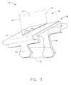
- Platform 38 Interfused with member 36 in the composite blading member 10 of the present invention is a platform shown generally at 38 in the perspective diagrammatic fragmentary view of Figure 3.
- a portion of member 36 of Figure 2 is shown in phantom at 36 in Figure 3.
- a portion of member 36 of Figure 2 is shown in phantom at 36 in Figure 3 to emphasize more clearly details of platform 38.
- Platform 38 comprises a platform shelf 42 surrounding and at an angle to the member 36 comprised of airfoil 12 and base 20 in Figure 2, with airfoil 20 being shown to project radially outward from platform 38.
- Platform 38 includes a plurality, for example a pair, of spaced-apart platform first and second supports 44 and 46 integral with platform shelf 42 and projecting angularly away from platform shelf 42 and blade tip or first end 14 (Figure 1) toward base for second end 22. Platform 38 also includes therethrough an airfoil shaped opening 43 defined by opening wall 45 which forms an interface with a surface of member 36 disposed through opening 43.
- platform first support 44 was shaped substantially to the shape of base first end surface 26 and platform second support 46 was shaped substantially to the shape of base second end surface 28.
- Platform 38 was made of a plurality of stacked layers or plies of composite material, in this embodiment a SiC-SiC CMC material.
- the composite material layers in shelf 42 were disposed at a second selected primary orientation, different from the first primary orientation of the layers in member 36, to enhance mechanical properties of platform 38 responsive to forces experienced by the platform during engine operation.
- platform first and second supports 44 and 46 were interfused respectively with base first and second end surfaces 26 and 28.
- interfused is intended to mean bonding of the cooperating members with a binder, for example Si in this embodiment, of a material that is compatible with and is disposed within the stack of composite material from which the members were made at a juxtaposed interface.
- Figure 4 is an enlarged fragmentary sectional view radially through blade 10 of Figure 3, viewed circumferentially. Shown is a disposition of a plurality of plies 40 in platform shelf 42 as well as in platform supports 44 and 46, with such platform supports interfused respectively at base end surfaces 28 and 26.
- composite blade 10 of the present invention was made by interfusing such platform supports with such base end surfaces while members 36 and 38, assembled as shown in Figure 3 and 4, were in a partially cured condition. Sometimes such condition is referred to in the art as being in the "green state".
- a platform preform associated with 38 comprising a plurality of stacked layers 40 of fibrous SiC-SiC CMC material.
- the platform preform included a platform shelf preform 38 and a pair of spaced-apart platform first and second support preforms 44 and 46, all generally related to those shown in and described in connection with Figure 3. Provision of such preforms in this example was made using a split tooling fixture of a type shown generally at 48 in the diagrammatic fragmentary, perspective view of Figure 5.
- Fixture 48 included a cavity 50 defined in part by a pair of spaced-apart removable projections 52 having opposed walls 54 facing one another.
- Cavity 50 included an airfoil shaped opening 56 therethrough.
- the layers were arranged to generate an airfoil shaped platform shelf opening 43 defined by opening wall 45 by extending the layers outwardly from and about opening 56, Figure 5.
- Such layers were arranged in the above-described second primary orientation selected to provide platform shelf 42 with desired mechanical properties.
- the layers were laid up to extend outwardly along walls 54 to provide spaced-apart platform support preforms related to platform supports 44 and 46.
- integral and coextensive airfoil-base preform shaped to relate to member 36 shown in Figure 2 was provided to cooperate with the platform preform in making blade 10 of the present invention.
- the airfoil-base preform related to member 36 was made of a plurality of partially cured stacked layers of fibrous SiC-SiC CMC material arranged in the first primary orientation selected to provide airfoil-base member 36 with desired mechanical properties.
- the airfoil 12 of the airfoil-base preform 36 was inserted radially inwardly to hang through airfoil shaped opening 43 of platform preform 38 with the airfoil shaped platform shelf opening wall 45 of the platform preform in juxtaposition at an airfoil interface with a surface of airfoil-base preform 36.
- the platform support preforms 44 and 46 were in juxtaposition at relative support interfaces with the respective base end surfaces 26 and 28 of the airfoil-base preform 36.
- Such assembly defined and provided a third preform used in the present method.
- the third preform thus assembled was heated in fixture 48 at a temperature and for a time, for example in ranges well known and widely used in the relevant art, sufficient to at least additionally partially but less than fully cure and bond or integrate the preforms into a blading member preform in a condition less than fully cured.
- the airfoil-base preform and the platform preform were bonded at interfaces with the airfoil shaped opening wall and with the relative support interfaces.
- the blading member preform was removed from the fixture and melt interfused or infiltrated with a molten binder compatible with the CMC materials of the blading member preform, in this example molten Si, at a temperature and for a time sufficient to substantially fully cure the blading member preform. Such preform was then finished to provide the final blade 10.
Applications Claiming Priority (1)
| Application Number | Priority Date | Filing Date | Title |
|---|---|---|---|
| US11/315,552 US7510379B2 (en) | 2005-12-22 | 2005-12-22 | Composite blading member and method for making |
Publications (3)
| Publication Number | Publication Date |
|---|---|
| EP1801354A2 true EP1801354A2 (de) | 2007-06-27 |
| EP1801354A3 EP1801354A3 (de) | 2011-01-05 |
| EP1801354B1 EP1801354B1 (de) | 2012-02-29 |
Family
ID=37865695
Family Applications (1)
| Application Number | Title | Priority Date | Filing Date |
|---|---|---|---|
| EP06126911A Active EP1801354B1 (de) | 2005-12-22 | 2006-12-21 | Schaufel aus Verbundmaterial und Verfahren zur Herstellung |
Country Status (8)
| Country | Link |
|---|---|
| US (1) | US7510379B2 (de) |
| EP (1) | EP1801354B1 (de) |
| JP (1) | JP4953796B2 (de) |
| CN (1) | CN101042055B (de) |
| AT (1) | ATE547590T1 (de) |
| CA (1) | CA2571903C (de) |
| MY (1) | MY142892A (de) |
| SG (1) | SG133576A1 (de) |
Cited By (13)
| Publication number | Priority date | Publication date | Assignee | Title |
|---|---|---|---|---|
| WO2010077401A3 (en) * | 2008-12-31 | 2010-10-07 | General Electric Company | Ceramic matrix composite blade having integral platform structures and methods of fabrication |
| FR2943942A1 (fr) * | 2009-04-06 | 2010-10-08 | Snecma | Procede de fabrication d'une aube de turbomachine en materiau composite |
| FR2950286A1 (fr) * | 2009-09-24 | 2011-03-25 | Snecma | Procede de fabrication d'une aube de turbomachine en materiau composite |
| FR2960589A1 (fr) * | 2010-05-28 | 2011-12-02 | Snecma | Roue a aubes pour une turbomachine, telle qu'un turboreacteur ou un turbopropulseur d'avion |
| FR2982635A1 (fr) * | 2011-11-15 | 2013-05-17 | Snecma | Roue a aubes pour une turbomachine |
| WO2014004098A1 (en) * | 2012-06-30 | 2014-01-03 | General Electric Company | A turbine blade sealing structure |
| CN103518038A (zh) * | 2011-05-13 | 2014-01-15 | 赫拉克勒斯公司 | 包括由复合材料制成且具有增加的根部的叶片的涡轮发动机转子 |
| US9376916B2 (en) | 2012-06-05 | 2016-06-28 | United Technologies Corporation | Assembled blade platform |
| EP2935794A4 (de) * | 2012-12-18 | 2016-08-31 | United Technologies Corp | Tragfläche und zusammengesetzte plattform mit konturierter endwand |
| EP2543823A3 (de) * | 2011-07-05 | 2016-10-26 | United Technologies Corporation | Komponente mit keramikmatrix-Verbundstruktur |
| EP3315727A1 (de) * | 2016-10-28 | 2018-05-02 | Rolls-Royce Corporation | Turbinenschaufel aus keramischem faserverbundwerkstoff |
| DE102018220723A1 (de) * | 2018-11-30 | 2020-06-04 | Siemens Aktiengesellschaft | Komplexer CMC-Formkörper |
| EP3388627B2 (de) † | 2011-06-30 | 2023-11-08 | RTX Corporation | Cmc-schaufel mit integraler 3d-webplattform |
Families Citing this family (75)
| Publication number | Priority date | Publication date | Assignee | Title |
|---|---|---|---|---|
| US7874804B1 (en) * | 2007-05-10 | 2011-01-25 | Florida Turbine Technologies, Inc. | Turbine blade with detached platform |
| US8408874B2 (en) * | 2008-04-11 | 2013-04-02 | United Technologies Corporation | Platformless turbine blade |
| US9062562B2 (en) * | 2008-11-28 | 2015-06-23 | Herakles | Composite material turbomachine engine blade or vane, compressor stator segment or turbine nozzle segment incorporating such vanes and method for manufacturing same |
| FR2939129B1 (fr) * | 2008-11-28 | 2014-08-22 | Snecma Propulsion Solide | Aube de turbomachine en materiau composite et procede pour sa fabrication. |
| FR2946999B1 (fr) * | 2009-06-18 | 2019-08-09 | Safran Aircraft Engines | Element de distributeur de turbine en cmc, procede pour sa fabrication, et distributeur et turbine a gaz l'incorporant. |
| FR2953553B1 (fr) * | 2009-12-09 | 2012-02-03 | Snecma | Aube de turbine de turbomachine en composite a matrice ceramique avec evidements realises par usinage |
| FR2953885B1 (fr) * | 2009-12-14 | 2012-02-10 | Snecma | Aube de turbomachine en materiau composite et procede pour sa fabrication |
| DE102010004854A1 (de) * | 2010-01-16 | 2011-07-21 | MTU Aero Engines GmbH, 80995 | Laufschaufel für eine Strömungsmaschine und Strömungsmaschine |
| US9228445B2 (en) * | 2010-12-23 | 2016-01-05 | General Electric Company | Turbine airfoil components containing ceramic-based materials and processes therefor |
| US8777583B2 (en) * | 2010-12-27 | 2014-07-15 | General Electric Company | Turbine airfoil components containing ceramic-based materials and processes therefor |
| US8740571B2 (en) | 2011-03-07 | 2014-06-03 | General Electric Company | Turbine bucket for use in gas turbine engines and methods for fabricating the same |
| US8475132B2 (en) * | 2011-03-16 | 2013-07-02 | General Electric Company | Turbine blade assembly |
| US8790067B2 (en) | 2011-04-27 | 2014-07-29 | United Technologies Corporation | Blade clearance control using high-CTE and low-CTE ring members |
| US9011085B2 (en) | 2011-05-26 | 2015-04-21 | United Technologies Corporation | Ceramic matrix composite continuous “I”-shaped fiber geometry airfoil for a gas turbine engine |
| US8944770B2 (en) | 2011-05-26 | 2015-02-03 | United Technologies Corporation | Integrated ceramic matrix composite rotor disk hub geometry for a gas turbine engine |
| US20120301269A1 (en) * | 2011-05-26 | 2012-11-29 | Ioannis Alvanos | Clearance control with ceramic matrix composite rotor assembly for a gas turbine engine |
| US8864492B2 (en) | 2011-06-23 | 2014-10-21 | United Technologies Corporation | Reverse flow combustor duct attachment |
| US8739547B2 (en) | 2011-06-23 | 2014-06-03 | United Technologies Corporation | Gas turbine engine joint having a metallic member, a CMC member, and a ceramic key |
| US9335051B2 (en) | 2011-07-13 | 2016-05-10 | United Technologies Corporation | Ceramic matrix composite combustor vane ring assembly |
| US8920127B2 (en) | 2011-07-18 | 2014-12-30 | United Technologies Corporation | Turbine rotor non-metallic blade attachment |
| FR2979662B1 (fr) * | 2011-09-07 | 2013-09-27 | Snecma | Procede de fabrication d'un secteur de distributeur de turbine ou redresseur de compresseur en materiau composite pour turbomachine et turbine ou compresseur incorporant un distributeur ou un redresseur forme de tels secteurs |
| US10287897B2 (en) * | 2011-09-08 | 2019-05-14 | General Electric Company | Turbine rotor blade assembly and method of assembling same |
| US8985956B2 (en) * | 2011-09-19 | 2015-03-24 | General Electric Company | Compressive stress system for a gas turbine engine |
| JP6174839B2 (ja) | 2011-10-14 | 2017-08-02 | 株式会社Ihi | セラミックス基複合部材およびその製造方法 |
| US9068476B2 (en) | 2011-12-22 | 2015-06-30 | Pratt & Whitney Canada Corp. | Hybrid metal/composite link rod for turbofan gas turbine engine |
| US8967974B2 (en) | 2012-01-03 | 2015-03-03 | General Electric Company | Composite airfoil assembly |
| US9308708B2 (en) * | 2012-03-23 | 2016-04-12 | General Electric Company | Process for producing ceramic composite components |
| JP6035826B2 (ja) * | 2012-04-10 | 2016-11-30 | 株式会社Ihi | タービン翼として用いるセラミックス基複合部材およびその製造方法 |
| US9410437B2 (en) | 2012-08-14 | 2016-08-09 | General Electric Company | Airfoil components containing ceramic-based materials and processes therefor |
| JP6003660B2 (ja) * | 2013-01-11 | 2016-10-05 | 株式会社Ihi | セラミックス基複合部材 |
| WO2014133721A1 (en) | 2013-02-27 | 2014-09-04 | United Technologies Corporation | Gas turbine engine thin wall composite vane airfoil |
| EP2961938B1 (de) | 2013-03-01 | 2019-12-18 | United Technologies Corporation | Verbundschaufel eines gasturbinenmotors und verfahren |
| CA2897058A1 (en) | 2013-03-04 | 2014-10-02 | Rolls-Royce North American Technologies, Inc. | Method for making gas turbine engine ceramic matrix composite airfoil |
| EP2971587B1 (de) | 2013-03-12 | 2020-02-05 | Rolls-Royce Corporation | Turbinenschaufelummantelungsvorrichtung |
| EP2971588A1 (de) | 2013-03-13 | 2016-01-20 | Rolls-Royce Corporation | Schwalbenschwanzhaltesystem für schaufelkanten |
| WO2014150370A1 (en) * | 2013-03-15 | 2014-09-25 | United Technologies Corporation | Transient liquid phase bonded tip shroud |
| EP2981676A4 (de) * | 2013-04-02 | 2016-12-07 | United Technologies Corp | Motorkomponente mit einem träger mit einer zwischenschicht |
| US9482108B2 (en) | 2013-04-03 | 2016-11-01 | General Electric Company | Turbomachine blade assembly |
| EP3044420A2 (de) | 2013-09-11 | 2016-07-20 | General Electric Company | Schichtarchitektur für eine integrierte plattform und dämpferrückhaltefunktionen in cmc-turbinenschaufeln |
| EP2902588B1 (de) * | 2014-01-31 | 2020-06-24 | Ansaldo Energia IP UK Limited | Verbundstoffturbinenschaufel für Hochtemperaturanwendungen |
| FR3021349B1 (fr) * | 2014-05-22 | 2021-07-02 | Herakles | Procede de fabrication d'une aube de turbomachine en materiau composite, aube ainsi obtenue et turbomachine l'incorporant |
| FR3037097B1 (fr) * | 2015-06-03 | 2017-06-23 | Snecma | Aube composite comprenant une plateforme munie d'un raidisseur |
| FR3029960B1 (fr) * | 2014-12-11 | 2021-06-04 | Snecma | Roue a aubes avec joint radial pour une turbine de turbomachine |
| US10253639B2 (en) * | 2015-02-05 | 2019-04-09 | Rolls-Royce North American Technologies, Inc. | Ceramic matrix composite gas turbine engine blade |
| US10563523B2 (en) | 2015-04-08 | 2020-02-18 | Rolls-Royce Corporation | Method for fabricating a ceramic matrix composite rotor blade |
| US10018054B2 (en) | 2015-10-23 | 2018-07-10 | General Electric Company | Fabrication of gas turbine engine components using multiple processing steps |
| US10227880B2 (en) | 2015-11-10 | 2019-03-12 | General Electric Company | Turbine blade attachment mechanism |
| US10316673B2 (en) | 2016-03-24 | 2019-06-11 | General Electric Company | CMC turbine blade platform damper |
| US11383494B2 (en) | 2016-07-01 | 2022-07-12 | General Electric Company | Ceramic matrix composite articles having different localized properties and methods for forming same |
| US10436036B2 (en) * | 2016-07-05 | 2019-10-08 | Safran Aircraft Engines | Fitted platform for a turbine engine fan, and a method of fabricating it |
| FR3057295B1 (fr) * | 2016-10-12 | 2020-12-11 | Safran Aircraft Engines | Aube comprenant une plate-forme et une pale assemblees |
| US10577939B2 (en) | 2016-11-01 | 2020-03-03 | Rolls-Royce Corporation | Turbine blade with three-dimensional CMC construction elements |
| US10731481B2 (en) | 2016-11-01 | 2020-08-04 | Rolls-Royce Corporation | Turbine blade with ceramic matrix composite material construction |
| US10358922B2 (en) | 2016-11-10 | 2019-07-23 | Rolls-Royce Corporation | Turbine wheel with circumferentially-installed inter-blade heat shields |
| US10767502B2 (en) | 2016-12-23 | 2020-09-08 | Rolls-Royce Corporation | Composite turbine vane with three-dimensional fiber reinforcements |
| FR3063448B1 (fr) * | 2017-03-01 | 2019-04-05 | Safran Aircraft Engines | Preforme et aube monobloc pour turbomachine |
| CN107266099B (zh) * | 2017-06-16 | 2023-07-18 | 中国人民解放军第五七一九工厂 | 一种航空发动机陶瓷基复合材料涡轮导向器叶片近净成型用夹具 |
| US10569481B2 (en) | 2017-06-26 | 2020-02-25 | General Electric Company | Shaped composite ply layups and methods for shaping composite ply layups |
| US20190153876A1 (en) * | 2017-11-21 | 2019-05-23 | General Electric Company | Nanostructure between plies of high temperature polymer matrix composite |
| CN108119188B (zh) * | 2017-12-19 | 2020-04-17 | 北京航空航天大学 | 一种陶瓷基复合材料涡轮转子叶片 |
| US11931981B2 (en) * | 2018-01-29 | 2024-03-19 | General Electric Company | Reinforced composite blade and method of making a blade |
| CN108640698A (zh) * | 2018-05-02 | 2018-10-12 | 中国航发北京航空材料研究院 | 一种陶瓷基复合材料构件共固化成型工艺 |
| US10677075B2 (en) | 2018-05-04 | 2020-06-09 | General Electric Company | Composite airfoil assembly for an interdigitated rotor |
| US10941665B2 (en) | 2018-05-04 | 2021-03-09 | General Electric Company | Composite airfoil assembly for an interdigitated rotor |
| US10738628B2 (en) * | 2018-05-25 | 2020-08-11 | General Electric Company | Joint for band features on turbine nozzle and fabrication |
| US10934854B2 (en) | 2018-09-11 | 2021-03-02 | General Electric Company | CMC component cooling cavities |
| US11040915B2 (en) | 2018-09-11 | 2021-06-22 | General Electric Company | Method of forming CMC component cooling cavities |
| US11131203B2 (en) | 2018-09-26 | 2021-09-28 | Rolls-Royce Corporation | Turbine wheel assembly with offloaded platforms and ceramic matrix composite blades |
| US11035239B2 (en) | 2018-10-25 | 2021-06-15 | General Electric Company | Ceramic matrix composite turbine nozzle shell and method of assembly |
| US11174203B2 (en) | 2018-10-25 | 2021-11-16 | General Electric Company | Ceramic matrix composite turbine nozzle shell and method of assembly |
| CN109928749A (zh) * | 2019-01-17 | 2019-06-25 | 内蒙古科技大学 | 一种大型风力发电机陶瓷叶片及其制备方法 |
| US11333037B2 (en) * | 2020-02-06 | 2022-05-17 | Raytheon Technologies Corporation | Vane arc segment load path |
| US11156110B1 (en) | 2020-08-04 | 2021-10-26 | General Electric Company | Rotor assembly for a turbine section of a gas turbine engine |
| US11655719B2 (en) | 2021-04-16 | 2023-05-23 | General Electric Company | Airfoil assembly |
| CN113107605B (zh) * | 2021-05-06 | 2021-12-07 | 南京航空航天大学 | 一种陶瓷基复合材料双t形涡轮转子叶片结构 |
Citations (3)
| Publication number | Priority date | Publication date | Assignee | Title |
|---|---|---|---|---|
| US5813188A (en) | 1997-07-18 | 1998-09-29 | Diane E. Miller | Accessory for building construction |
| US6106231A (en) | 1998-11-06 | 2000-08-22 | General Electric Company | Partially coated airfoil and method for making |
| EP1555391A2 (de) | 2004-01-15 | 2005-07-20 | General Electric Company | Turbinenschaufel bestehend aus einem hybriden keramischen Matrix-Verbundwerkstoff |
Family Cites Families (11)
| Publication number | Priority date | Publication date | Assignee | Title |
|---|---|---|---|---|
| US4022547A (en) * | 1975-10-02 | 1977-05-10 | General Electric Company | Composite blade employing biased layup |
| FR2608674B1 (fr) * | 1986-12-17 | 1991-04-19 | Snecma | Roue de turbine a aubes ceramique |
| JPS6456902A (en) * | 1987-08-28 | 1989-03-03 | Ishikawajima Harima Heavy Ind | Moving blade with platform |
| US5375978A (en) * | 1992-05-01 | 1994-12-27 | General Electric Company | Foreign object damage resistant composite blade and manufacture |
| JPH07189606A (ja) * | 1993-12-28 | 1995-07-28 | Toshiba Corp | ガスタービン動翼およびその動翼製造用繊維強化セラミックス基複合材料ならびにガスタービン動翼の製造方法 |
| US5939006A (en) * | 1995-06-28 | 1999-08-17 | General Electric Company | Method for forming a composite airfoil structure |
| FR2817192B1 (fr) * | 2000-11-28 | 2003-08-08 | Snecma Moteurs | Ensemble forme par au moins une pale et une plate-forme de fixation de la pale, pour une turbomachine, et procede pour sa fabrication |
| US6821087B2 (en) * | 2002-01-21 | 2004-11-23 | Honda Giken Kogyo Kabushiki Kaisha | Flow-rectifying member and its unit and method for producing flow-rectifying member |
| US7093359B2 (en) * | 2002-09-17 | 2006-08-22 | Siemens Westinghouse Power Corporation | Composite structure formed by CMC-on-insulation process |
| CN100353030C (zh) * | 2003-04-19 | 2007-12-05 | 通用电气公司 | 多组件混合式涡轮叶片 |
| US7306826B2 (en) * | 2004-02-23 | 2007-12-11 | General Electric Company | Use of biased fabric to improve properties of SiC/SiC ceramic composites for turbine engine components |
-
2005
- 2005-12-22 US US11/315,552 patent/US7510379B2/en active Active
-
2006
- 2006-12-21 EP EP06126911A patent/EP1801354B1/de active Active
- 2006-12-21 AT AT06126911T patent/ATE547590T1/de active
- 2006-12-21 SG SG200608994-0A patent/SG133576A1/en unknown
- 2006-12-21 CA CA2571903A patent/CA2571903C/en active Active
- 2006-12-21 MY MYPI20064730A patent/MY142892A/en unknown
- 2006-12-22 JP JP2006345670A patent/JP4953796B2/ja active Active
- 2006-12-22 CN CN200610064093.XA patent/CN101042055B/zh active Active
Patent Citations (3)
| Publication number | Priority date | Publication date | Assignee | Title |
|---|---|---|---|---|
| US5813188A (en) | 1997-07-18 | 1998-09-29 | Diane E. Miller | Accessory for building construction |
| US6106231A (en) | 1998-11-06 | 2000-08-22 | General Electric Company | Partially coated airfoil and method for making |
| EP1555391A2 (de) | 2004-01-15 | 2005-07-20 | General Electric Company | Turbinenschaufel bestehend aus einem hybriden keramischen Matrix-Verbundwerkstoff |
Cited By (29)
| Publication number | Priority date | Publication date | Assignee | Title |
|---|---|---|---|---|
| GB2478673A (en) * | 2008-12-31 | 2011-09-14 | Gen Electric | Ceramic matrix composite blade having integral platform structures and methods of fabrication |
| US8714932B2 (en) | 2008-12-31 | 2014-05-06 | General Electric Company | Ceramic matrix composite blade having integral platform structures and methods of fabrication |
| GB2478673B (en) * | 2008-12-31 | 2014-04-30 | Gen Electric | Ceramic matrix composite blade having integral platform structures and methods of fabrication |
| WO2010077401A3 (en) * | 2008-12-31 | 2010-10-07 | General Electric Company | Ceramic matrix composite blade having integral platform structures and methods of fabrication |
| CN102387908A (zh) * | 2009-04-06 | 2012-03-21 | 斯奈克玛 | 一种用复合材料制成的涡轮机叶片的制造方法 |
| CN102387908B (zh) * | 2009-04-06 | 2014-11-19 | 斯奈克玛 | 一种用复合材料制成的涡轮机叶片的制造方法 |
| US8607454B2 (en) | 2009-04-06 | 2013-12-17 | Snecma | Method for producing a turbomachine blade made from a composite material |
| WO2010116066A1 (fr) * | 2009-04-06 | 2010-10-14 | Snecma | Procede de fabrication d'une aube de turbomachine en materiau composite |
| FR2943942A1 (fr) * | 2009-04-06 | 2010-10-08 | Snecma | Procede de fabrication d'une aube de turbomachine en materiau composite |
| RU2523308C2 (ru) * | 2009-04-06 | 2014-07-20 | Снекма | Способ изготовления турбомашинной лопатки, сделанной из композиционного материала |
| FR2950286A1 (fr) * | 2009-09-24 | 2011-03-25 | Snecma | Procede de fabrication d'une aube de turbomachine en materiau composite |
| WO2011036380A1 (fr) * | 2009-09-24 | 2011-03-31 | Snecma | Procede et moule de fabrication d' une aube de turbomachine en materiau compos ite |
| US8980031B2 (en) | 2009-09-24 | 2015-03-17 | Snecma | Method of fabricating a turbine engine blade out of composite material |
| FR2960589A1 (fr) * | 2010-05-28 | 2011-12-02 | Snecma | Roue a aubes pour une turbomachine, telle qu'un turboreacteur ou un turbopropulseur d'avion |
| CN103518038B (zh) * | 2011-05-13 | 2016-10-12 | 赫拉克勒斯公司 | 包括由复合材料制成且具有增加的根部的叶片的涡轮发动机转子 |
| CN103518038A (zh) * | 2011-05-13 | 2014-01-15 | 赫拉克勒斯公司 | 包括由复合材料制成且具有增加的根部的叶片的涡轮发动机转子 |
| EP3388627B2 (de) † | 2011-06-30 | 2023-11-08 | RTX Corporation | Cmc-schaufel mit integraler 3d-webplattform |
| EP2543823A3 (de) * | 2011-07-05 | 2016-10-26 | United Technologies Corporation | Komponente mit keramikmatrix-Verbundstruktur |
| US9726033B2 (en) | 2011-11-15 | 2017-08-08 | Snecma | Rotor wheel for a turbine engine |
| WO2013072605A1 (fr) * | 2011-11-15 | 2013-05-23 | Snecma | Roue a aubes pour une turbomachine |
| FR2982635A1 (fr) * | 2011-11-15 | 2013-05-17 | Snecma | Roue a aubes pour une turbomachine |
| US9376916B2 (en) | 2012-06-05 | 2016-06-28 | United Technologies Corporation | Assembled blade platform |
| WO2014004098A1 (en) * | 2012-06-30 | 2014-01-03 | General Electric Company | A turbine blade sealing structure |
| US10648352B2 (en) | 2012-06-30 | 2020-05-12 | General Electric Company | Turbine blade sealing structure |
| EP2935794A4 (de) * | 2012-12-18 | 2016-08-31 | United Technologies Corp | Tragfläche und zusammengesetzte plattform mit konturierter endwand |
| US9598967B2 (en) | 2012-12-18 | 2017-03-21 | United Technologies Corporation | Airfoil member and composite platform having contoured endwall |
| EP3315727A1 (de) * | 2016-10-28 | 2018-05-02 | Rolls-Royce Corporation | Turbinenschaufel aus keramischem faserverbundwerkstoff |
| US10443409B2 (en) | 2016-10-28 | 2019-10-15 | Rolls-Royce North American Technologies Inc. | Turbine blade with ceramic matrix composite material construction |
| DE102018220723A1 (de) * | 2018-11-30 | 2020-06-04 | Siemens Aktiengesellschaft | Komplexer CMC-Formkörper |
Also Published As
| Publication number | Publication date |
|---|---|
| CN101042055B (zh) | 2011-08-03 |
| MY142892A (en) | 2011-01-31 |
| JP2007205350A (ja) | 2007-08-16 |
| CA2571903C (en) | 2014-08-12 |
| CN101042055A (zh) | 2007-09-26 |
| EP1801354B1 (de) | 2012-02-29 |
| US20070148000A1 (en) | 2007-06-28 |
| SG133576A1 (en) | 2007-07-30 |
| EP1801354A3 (de) | 2011-01-05 |
| JP4953796B2 (ja) | 2012-06-13 |
| CA2571903A1 (en) | 2007-06-22 |
| ATE547590T1 (de) | 2012-03-15 |
| US7510379B2 (en) | 2009-03-31 |
Similar Documents
| Publication | Publication Date | Title |
|---|---|---|
| EP1801354B1 (de) | Schaufel aus Verbundmaterial und Verfahren zur Herstellung | |
| US11306617B2 (en) | Shroud for a gas turbine engine | |
| US6190133B1 (en) | High stiffness airoil and method of manufacture | |
| US10415394B2 (en) | Gas turbine engine blade with ceramic tip and cooling arrangement | |
| EP3023581B1 (de) | Turbinendiskanordnung mit keramikmatrix-verbundstoffschaufeln und verfahren zur herstellung | |
| EP2613015B1 (de) | Äußere hybride Laufschaufelluftdichtung für einen Gasturbinenmotor | |
| US4335997A (en) | Stress resistant hybrid radial turbine wheel | |
| EP3339573B1 (de) | Zusammengesetzte turbinenschaufel mit verstärkungen aus dreidimensionalen fasern | |
| US20150093249A1 (en) | Blade for a gas turbine | |
| EP2831377B1 (de) | Hybridschaufel für einen gasturbinenmotor | |
| US10822973B2 (en) | Shroud for a gas turbine engine | |
| EP2653652B1 (de) | Axial aufgeteilte Radialturbine | |
| EP3017149B1 (de) | Schaufel und verfahren zu deren herstellung | |
| US20180298765A1 (en) | Engine component with replaceable tip element | |
| JP2012026448A (ja) | 接合縁部を備えた構成要素 | |
| US20220275730A1 (en) | Fairing assembly | |
| CN114135342A (zh) | 具有带有复合物和金属部分的根部区段的燃气涡轮发动机转子叶片 |
Legal Events
| Date | Code | Title | Description |
|---|---|---|---|
| PUAI | Public reference made under article 153(3) epc to a published international application that has entered the european phase |
Free format text: ORIGINAL CODE: 0009012 |
|
| AK | Designated contracting states |
Kind code of ref document: A2 Designated state(s): AT BE BG CH CY CZ DE DK EE ES FI FR GB GR HU IE IS IT LI LT LU LV MC NL PL PT RO SE SI SK TR |
|
| AX | Request for extension of the european patent |
Extension state: AL BA HR MK YU |
|
| PUAL | Search report despatched |
Free format text: ORIGINAL CODE: 0009013 |
|
| AK | Designated contracting states |
Kind code of ref document: A3 Designated state(s): AT BE BG CH CY CZ DE DK EE ES FI FR GB GR HU IE IS IT LI LT LU LV MC NL PL PT RO SE SI SK TR |
|
| AX | Request for extension of the european patent |
Extension state: AL BA HR MK RS |
|
| 17P | Request for examination filed |
Effective date: 20110705 |
|
| AKX | Designation fees paid |
Designated state(s): AT BE BG CH CY CZ DE DK EE ES FI FR GB GR HU IE IS IT LI LT LU LV MC NL PL PT RO SE SI SK TR |
|
| GRAP | Despatch of communication of intention to grant a patent |
Free format text: ORIGINAL CODE: EPIDOSNIGR1 |
|
| GRAS | Grant fee paid |
Free format text: ORIGINAL CODE: EPIDOSNIGR3 |
|
| GRAA | (expected) grant |
Free format text: ORIGINAL CODE: 0009210 |
|
| AK | Designated contracting states |
Kind code of ref document: B1 Designated state(s): AT BE BG CH CY CZ DE DK EE ES FI FR GB GR HU IE IS IT LI LT LU LV MC NL PL PT RO SE SI SK TR |
|
| REG | Reference to a national code |
Ref country code: GB Ref legal event code: FG4D Ref country code: CH Ref legal event code: EP |
|
| REG | Reference to a national code |
Ref country code: AT Ref legal event code: REF Ref document number: 547590 Country of ref document: AT Kind code of ref document: T Effective date: 20120315 |
|
| REG | Reference to a national code |
Ref country code: IE Ref legal event code: FG4D |
|
| REG | Reference to a national code |
Ref country code: DE Ref legal event code: R096 Ref document number: 602006027893 Country of ref document: DE Effective date: 20120426 |
|
| REG | Reference to a national code |
Ref country code: NL Ref legal event code: VDEP Effective date: 20120229 |
|
| LTIE | Lt: invalidation of european patent or patent extension |
Effective date: 20120229 |
|
| PG25 | Lapsed in a contracting state [announced via postgrant information from national office to epo] |
Ref country code: IS Free format text: LAPSE BECAUSE OF FAILURE TO SUBMIT A TRANSLATION OF THE DESCRIPTION OR TO PAY THE FEE WITHIN THE PRESCRIBED TIME-LIMIT Effective date: 20120629 Ref country code: NL Free format text: LAPSE BECAUSE OF FAILURE TO SUBMIT A TRANSLATION OF THE DESCRIPTION OR TO PAY THE FEE WITHIN THE PRESCRIBED TIME-LIMIT Effective date: 20120229 Ref country code: LT Free format text: LAPSE BECAUSE OF FAILURE TO SUBMIT A TRANSLATION OF THE DESCRIPTION OR TO PAY THE FEE WITHIN THE PRESCRIBED TIME-LIMIT Effective date: 20120229 |
|
| PG25 | Lapsed in a contracting state [announced via postgrant information from national office to epo] |
Ref country code: PT Free format text: LAPSE BECAUSE OF FAILURE TO SUBMIT A TRANSLATION OF THE DESCRIPTION OR TO PAY THE FEE WITHIN THE PRESCRIBED TIME-LIMIT Effective date: 20120629 Ref country code: GR Free format text: LAPSE BECAUSE OF FAILURE TO SUBMIT A TRANSLATION OF THE DESCRIPTION OR TO PAY THE FEE WITHIN THE PRESCRIBED TIME-LIMIT Effective date: 20120530 Ref country code: FI Free format text: LAPSE BECAUSE OF FAILURE TO SUBMIT A TRANSLATION OF THE DESCRIPTION OR TO PAY THE FEE WITHIN THE PRESCRIBED TIME-LIMIT Effective date: 20120229 Ref country code: LV Free format text: LAPSE BECAUSE OF FAILURE TO SUBMIT A TRANSLATION OF THE DESCRIPTION OR TO PAY THE FEE WITHIN THE PRESCRIBED TIME-LIMIT Effective date: 20120229 Ref country code: BE Free format text: LAPSE BECAUSE OF FAILURE TO SUBMIT A TRANSLATION OF THE DESCRIPTION OR TO PAY THE FEE WITHIN THE PRESCRIBED TIME-LIMIT Effective date: 20120229 |
|
| REG | Reference to a national code |
Ref country code: AT Ref legal event code: MK05 Ref document number: 547590 Country of ref document: AT Kind code of ref document: T Effective date: 20120229 |
|
| PG25 | Lapsed in a contracting state [announced via postgrant information from national office to epo] |
Ref country code: CY Free format text: LAPSE BECAUSE OF FAILURE TO SUBMIT A TRANSLATION OF THE DESCRIPTION OR TO PAY THE FEE WITHIN THE PRESCRIBED TIME-LIMIT Effective date: 20120229 |
|
| PG25 | Lapsed in a contracting state [announced via postgrant information from national office to epo] |
Ref country code: DK Free format text: LAPSE BECAUSE OF FAILURE TO SUBMIT A TRANSLATION OF THE DESCRIPTION OR TO PAY THE FEE WITHIN THE PRESCRIBED TIME-LIMIT Effective date: 20120229 Ref country code: CZ Free format text: LAPSE BECAUSE OF FAILURE TO SUBMIT A TRANSLATION OF THE DESCRIPTION OR TO PAY THE FEE WITHIN THE PRESCRIBED TIME-LIMIT Effective date: 20120229 Ref country code: SE Free format text: LAPSE BECAUSE OF FAILURE TO SUBMIT A TRANSLATION OF THE DESCRIPTION OR TO PAY THE FEE WITHIN THE PRESCRIBED TIME-LIMIT Effective date: 20120229 Ref country code: RO Free format text: LAPSE BECAUSE OF FAILURE TO SUBMIT A TRANSLATION OF THE DESCRIPTION OR TO PAY THE FEE WITHIN THE PRESCRIBED TIME-LIMIT Effective date: 20120229 Ref country code: PL Free format text: LAPSE BECAUSE OF FAILURE TO SUBMIT A TRANSLATION OF THE DESCRIPTION OR TO PAY THE FEE WITHIN THE PRESCRIBED TIME-LIMIT Effective date: 20120229 Ref country code: SI Free format text: LAPSE BECAUSE OF FAILURE TO SUBMIT A TRANSLATION OF THE DESCRIPTION OR TO PAY THE FEE WITHIN THE PRESCRIBED TIME-LIMIT Effective date: 20120229 Ref country code: EE Free format text: LAPSE BECAUSE OF FAILURE TO SUBMIT A TRANSLATION OF THE DESCRIPTION OR TO PAY THE FEE WITHIN THE PRESCRIBED TIME-LIMIT Effective date: 20120229 |
|
| PG25 | Lapsed in a contracting state [announced via postgrant information from national office to epo] |
Ref country code: SK Free format text: LAPSE BECAUSE OF FAILURE TO SUBMIT A TRANSLATION OF THE DESCRIPTION OR TO PAY THE FEE WITHIN THE PRESCRIBED TIME-LIMIT Effective date: 20120229 |
|
| PLBE | No opposition filed within time limit |
Free format text: ORIGINAL CODE: 0009261 |
|
| STAA | Information on the status of an ep patent application or granted ep patent |
Free format text: STATUS: NO OPPOSITION FILED WITHIN TIME LIMIT |
|
| PG25 | Lapsed in a contracting state [announced via postgrant information from national office to epo] |
Ref country code: AT Free format text: LAPSE BECAUSE OF FAILURE TO SUBMIT A TRANSLATION OF THE DESCRIPTION OR TO PAY THE FEE WITHIN THE PRESCRIBED TIME-LIMIT Effective date: 20120229 |
|
| 26N | No opposition filed |
Effective date: 20121130 |
|
| REG | Reference to a national code |
Ref country code: DE Ref legal event code: R097 Ref document number: 602006027893 Country of ref document: DE Effective date: 20121130 |
|
| PG25 | Lapsed in a contracting state [announced via postgrant information from national office to epo] |
Ref country code: ES Free format text: LAPSE BECAUSE OF FAILURE TO SUBMIT A TRANSLATION OF THE DESCRIPTION OR TO PAY THE FEE WITHIN THE PRESCRIBED TIME-LIMIT Effective date: 20120609 |
|
| PG25 | Lapsed in a contracting state [announced via postgrant information from national office to epo] |
Ref country code: MC Free format text: LAPSE BECAUSE OF NON-PAYMENT OF DUE FEES Effective date: 20121231 Ref country code: BG Free format text: LAPSE BECAUSE OF FAILURE TO SUBMIT A TRANSLATION OF THE DESCRIPTION OR TO PAY THE FEE WITHIN THE PRESCRIBED TIME-LIMIT Effective date: 20120529 |
|
| REG | Reference to a national code |
Ref country code: CH Ref legal event code: PL |
|
| REG | Reference to a national code |
Ref country code: IE Ref legal event code: MM4A |
|
| PG25 | Lapsed in a contracting state [announced via postgrant information from national office to epo] |
Ref country code: CH Free format text: LAPSE BECAUSE OF NON-PAYMENT OF DUE FEES Effective date: 20121231 Ref country code: LI Free format text: LAPSE BECAUSE OF NON-PAYMENT OF DUE FEES Effective date: 20121231 Ref country code: IE Free format text: LAPSE BECAUSE OF NON-PAYMENT OF DUE FEES Effective date: 20121221 |
|
| PG25 | Lapsed in a contracting state [announced via postgrant information from national office to epo] |
Ref country code: TR Free format text: LAPSE BECAUSE OF FAILURE TO SUBMIT A TRANSLATION OF THE DESCRIPTION OR TO PAY THE FEE WITHIN THE PRESCRIBED TIME-LIMIT Effective date: 20120229 |
|
| PG25 | Lapsed in a contracting state [announced via postgrant information from national office to epo] |
Ref country code: LU Free format text: LAPSE BECAUSE OF NON-PAYMENT OF DUE FEES Effective date: 20121221 |
|
| PG25 | Lapsed in a contracting state [announced via postgrant information from national office to epo] |
Ref country code: HU Free format text: LAPSE BECAUSE OF FAILURE TO SUBMIT A TRANSLATION OF THE DESCRIPTION OR TO PAY THE FEE WITHIN THE PRESCRIBED TIME-LIMIT Effective date: 20061221 |
|
| REG | Reference to a national code |
Ref country code: FR Ref legal event code: PLFP Year of fee payment: 10 |
|
| REG | Reference to a national code |
Ref country code: FR Ref legal event code: PLFP Year of fee payment: 11 |
|
| PG25 | Lapsed in a contracting state [announced via postgrant information from national office to epo] |
Ref country code: IT Free format text: LAPSE BECAUSE OF NON-PAYMENT OF DUE FEES Effective date: 20151221 |
|
| PG25 | Lapsed in a contracting state [announced via postgrant information from national office to epo] |
Ref country code: IT Free format text: LAPSE BECAUSE OF NON-PAYMENT OF DUE FEES Effective date: 20151221 |
|
| PGRI | Patent reinstated in contracting state [announced from national office to epo] |
Ref country code: IT Effective date: 20170710 |
|
| REG | Reference to a national code |
Ref country code: FR Ref legal event code: PLFP Year of fee payment: 12 |
|
| PGFP | Annual fee paid to national office [announced via postgrant information from national office to epo] |
Ref country code: IT Payment date: 20191121 Year of fee payment: 14 |
|
| PG25 | Lapsed in a contracting state [announced via postgrant information from national office to epo] |
Ref country code: IT Free format text: LAPSE BECAUSE OF NON-PAYMENT OF DUE FEES Effective date: 20201221 |
|
| P01 | Opt-out of the competence of the unified patent court (upc) registered |
Effective date: 20230414 |
|
| PGFP | Annual fee paid to national office [announced via postgrant information from national office to epo] |
Ref country code: GB Payment date: 20231121 Year of fee payment: 18 |
|
| PGFP | Annual fee paid to national office [announced via postgrant information from national office to epo] |
Ref country code: FR Payment date: 20231122 Year of fee payment: 18 Ref country code: DE Payment date: 20231121 Year of fee payment: 18 |