US11035239B2 - Ceramic matrix composite turbine nozzle shell and method of assembly - Google Patents
Ceramic matrix composite turbine nozzle shell and method of assembly Download PDFInfo
- Publication number
- US11035239B2 US11035239B2 US16/170,794 US201816170794A US11035239B2 US 11035239 B2 US11035239 B2 US 11035239B2 US 201816170794 A US201816170794 A US 201816170794A US 11035239 B2 US11035239 B2 US 11035239B2
- Authority
- US
- United States
- Prior art keywords
- platform
- plies
- primary
- nozzle
- stacked
- Prior art date
- Legal status (The legal status is an assumption and is not a legal conclusion. Google has not performed a legal analysis and makes no representation as to the accuracy of the status listed.)
- Active, expires
Links
Images


Classifications
-
- B—PERFORMING OPERATIONS; TRANSPORTING
- B32—LAYERED PRODUCTS
- B32B—LAYERED PRODUCTS, i.e. PRODUCTS BUILT-UP OF STRATA OF FLAT OR NON-FLAT, e.g. CELLULAR OR HONEYCOMB, FORM
- B32B18/00—Layered products essentially comprising ceramics, e.g. refractory products
-
- F—MECHANICAL ENGINEERING; LIGHTING; HEATING; WEAPONS; BLASTING
- F01—MACHINES OR ENGINES IN GENERAL; ENGINE PLANTS IN GENERAL; STEAM ENGINES
- F01D—NON-POSITIVE DISPLACEMENT MACHINES OR ENGINES, e.g. STEAM TURBINES
- F01D9/00—Stators
- F01D9/02—Nozzles; Nozzle boxes; Stator blades; Guide conduits, e.g. individual nozzles
- F01D9/04—Nozzles; Nozzle boxes; Stator blades; Guide conduits, e.g. individual nozzles forming ring or sector
- F01D9/041—Nozzles; Nozzle boxes; Stator blades; Guide conduits, e.g. individual nozzles forming ring or sector using blades
-
- C—CHEMISTRY; METALLURGY
- C04—CEMENTS; CONCRETE; ARTIFICIAL STONE; CERAMICS; REFRACTORIES
- C04B—LIME, MAGNESIA; SLAG; CEMENTS; COMPOSITIONS THEREOF, e.g. MORTARS, CONCRETE OR LIKE BUILDING MATERIALS; ARTIFICIAL STONE; CERAMICS; REFRACTORIES; TREATMENT OF NATURAL STONE
- C04B35/00—Shaped ceramic products characterised by their composition; Ceramics compositions; Processing powders of inorganic compounds preparatory to the manufacturing of ceramic products
- C04B35/01—Shaped ceramic products characterised by their composition; Ceramics compositions; Processing powders of inorganic compounds preparatory to the manufacturing of ceramic products based on oxide ceramics
-
- C—CHEMISTRY; METALLURGY
- C04—CEMENTS; CONCRETE; ARTIFICIAL STONE; CERAMICS; REFRACTORIES
- C04B—LIME, MAGNESIA; SLAG; CEMENTS; COMPOSITIONS THEREOF, e.g. MORTARS, CONCRETE OR LIKE BUILDING MATERIALS; ARTIFICIAL STONE; CERAMICS; REFRACTORIES; TREATMENT OF NATURAL STONE
- C04B35/00—Shaped ceramic products characterised by their composition; Ceramics compositions; Processing powders of inorganic compounds preparatory to the manufacturing of ceramic products
- C04B35/515—Shaped ceramic products characterised by their composition; Ceramics compositions; Processing powders of inorganic compounds preparatory to the manufacturing of ceramic products based on non-oxide ceramics
- C04B35/56—Shaped ceramic products characterised by their composition; Ceramics compositions; Processing powders of inorganic compounds preparatory to the manufacturing of ceramic products based on non-oxide ceramics based on carbides or oxycarbides
- C04B35/565—Shaped ceramic products characterised by their composition; Ceramics compositions; Processing powders of inorganic compounds preparatory to the manufacturing of ceramic products based on non-oxide ceramics based on carbides or oxycarbides based on silicon carbide
- C04B35/571—Shaped ceramic products characterised by their composition; Ceramics compositions; Processing powders of inorganic compounds preparatory to the manufacturing of ceramic products based on non-oxide ceramics based on carbides or oxycarbides based on silicon carbide obtained from Si-containing polymer precursors or organosilicon monomers
-
- C—CHEMISTRY; METALLURGY
- C04—CEMENTS; CONCRETE; ARTIFICIAL STONE; CERAMICS; REFRACTORIES
- C04B—LIME, MAGNESIA; SLAG; CEMENTS; COMPOSITIONS THEREOF, e.g. MORTARS, CONCRETE OR LIKE BUILDING MATERIALS; ARTIFICIAL STONE; CERAMICS; REFRACTORIES; TREATMENT OF NATURAL STONE
- C04B35/00—Shaped ceramic products characterised by their composition; Ceramics compositions; Processing powders of inorganic compounds preparatory to the manufacturing of ceramic products
- C04B35/515—Shaped ceramic products characterised by their composition; Ceramics compositions; Processing powders of inorganic compounds preparatory to the manufacturing of ceramic products based on non-oxide ceramics
- C04B35/56—Shaped ceramic products characterised by their composition; Ceramics compositions; Processing powders of inorganic compounds preparatory to the manufacturing of ceramic products based on non-oxide ceramics based on carbides or oxycarbides
- C04B35/565—Shaped ceramic products characterised by their composition; Ceramics compositions; Processing powders of inorganic compounds preparatory to the manufacturing of ceramic products based on non-oxide ceramics based on carbides or oxycarbides based on silicon carbide
- C04B35/573—Shaped ceramic products characterised by their composition; Ceramics compositions; Processing powders of inorganic compounds preparatory to the manufacturing of ceramic products based on non-oxide ceramics based on carbides or oxycarbides based on silicon carbide obtained by reaction sintering or recrystallisation
-
- C—CHEMISTRY; METALLURGY
- C04—CEMENTS; CONCRETE; ARTIFICIAL STONE; CERAMICS; REFRACTORIES
- C04B—LIME, MAGNESIA; SLAG; CEMENTS; COMPOSITIONS THEREOF, e.g. MORTARS, CONCRETE OR LIKE BUILDING MATERIALS; ARTIFICIAL STONE; CERAMICS; REFRACTORIES; TREATMENT OF NATURAL STONE
- C04B35/00—Shaped ceramic products characterised by their composition; Ceramics compositions; Processing powders of inorganic compounds preparatory to the manufacturing of ceramic products
- C04B35/622—Forming processes; Processing powders of inorganic compounds preparatory to the manufacturing of ceramic products
- C04B35/626—Preparing or treating the powders individually or as batches ; preparing or treating macroscopic reinforcing agents for ceramic products, e.g. fibres; mechanical aspects section B
- C04B35/628—Coating the powders or the macroscopic reinforcing agents
- C04B35/62844—Coating fibres
- C04B35/62857—Coating fibres with non-oxide ceramics
- C04B35/6286—Carbides
- C04B35/62863—Silicon carbide
-
- C—CHEMISTRY; METALLURGY
- C04—CEMENTS; CONCRETE; ARTIFICIAL STONE; CERAMICS; REFRACTORIES
- C04B—LIME, MAGNESIA; SLAG; CEMENTS; COMPOSITIONS THEREOF, e.g. MORTARS, CONCRETE OR LIKE BUILDING MATERIALS; ARTIFICIAL STONE; CERAMICS; REFRACTORIES; TREATMENT OF NATURAL STONE
- C04B35/00—Shaped ceramic products characterised by their composition; Ceramics compositions; Processing powders of inorganic compounds preparatory to the manufacturing of ceramic products
- C04B35/622—Forming processes; Processing powders of inorganic compounds preparatory to the manufacturing of ceramic products
- C04B35/626—Preparing or treating the powders individually or as batches ; preparing or treating macroscopic reinforcing agents for ceramic products, e.g. fibres; mechanical aspects section B
- C04B35/628—Coating the powders or the macroscopic reinforcing agents
- C04B35/62844—Coating fibres
- C04B35/62857—Coating fibres with non-oxide ceramics
- C04B35/62873—Carbon
-
- C—CHEMISTRY; METALLURGY
- C04—CEMENTS; CONCRETE; ARTIFICIAL STONE; CERAMICS; REFRACTORIES
- C04B—LIME, MAGNESIA; SLAG; CEMENTS; COMPOSITIONS THEREOF, e.g. MORTARS, CONCRETE OR LIKE BUILDING MATERIALS; ARTIFICIAL STONE; CERAMICS; REFRACTORIES; TREATMENT OF NATURAL STONE
- C04B35/00—Shaped ceramic products characterised by their composition; Ceramics compositions; Processing powders of inorganic compounds preparatory to the manufacturing of ceramic products
- C04B35/71—Ceramic products containing macroscopic reinforcing agents
- C04B35/78—Ceramic products containing macroscopic reinforcing agents containing non-metallic materials
- C04B35/80—Fibres, filaments, whiskers, platelets, or the like
-
- C—CHEMISTRY; METALLURGY
- C04—CEMENTS; CONCRETE; ARTIFICIAL STONE; CERAMICS; REFRACTORIES
- C04B—LIME, MAGNESIA; SLAG; CEMENTS; COMPOSITIONS THEREOF, e.g. MORTARS, CONCRETE OR LIKE BUILDING MATERIALS; ARTIFICIAL STONE; CERAMICS; REFRACTORIES; TREATMENT OF NATURAL STONE
- C04B41/00—After-treatment of mortars, concrete, artificial stone or ceramics; Treatment of natural stone
- C04B41/45—Coating or impregnating, e.g. injection in masonry, partial coating of green or fired ceramics, organic coating compositions for adhering together two concrete elements
- C04B41/50—Coating or impregnating, e.g. injection in masonry, partial coating of green or fired ceramics, organic coating compositions for adhering together two concrete elements with inorganic materials
- C04B41/5053—Coating or impregnating, e.g. injection in masonry, partial coating of green or fired ceramics, organic coating compositions for adhering together two concrete elements with inorganic materials non-oxide ceramics
- C04B41/5057—Carbides
- C04B41/5059—Silicon carbide
-
- F—MECHANICAL ENGINEERING; LIGHTING; HEATING; WEAPONS; BLASTING
- F01—MACHINES OR ENGINES IN GENERAL; ENGINE PLANTS IN GENERAL; STEAM ENGINES
- F01D—NON-POSITIVE DISPLACEMENT MACHINES OR ENGINES, e.g. STEAM TURBINES
- F01D5/00—Blades; Blade-carrying members; Heating, heat-insulating, cooling or antivibration means on the blades or the members
- F01D5/12—Blades
- F01D5/28—Selecting particular materials; Particular measures relating thereto; Measures against erosion or corrosion
- F01D5/282—Selecting composite materials, e.g. blades with reinforcing filaments
-
- F—MECHANICAL ENGINEERING; LIGHTING; HEATING; WEAPONS; BLASTING
- F01—MACHINES OR ENGINES IN GENERAL; ENGINE PLANTS IN GENERAL; STEAM ENGINES
- F01D—NON-POSITIVE DISPLACEMENT MACHINES OR ENGINES, e.g. STEAM TURBINES
- F01D5/00—Blades; Blade-carrying members; Heating, heat-insulating, cooling or antivibration means on the blades or the members
- F01D5/12—Blades
- F01D5/28—Selecting particular materials; Particular measures relating thereto; Measures against erosion or corrosion
- F01D5/284—Selection of ceramic materials
-
- B—PERFORMING OPERATIONS; TRANSPORTING
- B32—LAYERED PRODUCTS
- B32B—LAYERED PRODUCTS, i.e. PRODUCTS BUILT-UP OF STRATA OF FLAT OR NON-FLAT, e.g. CELLULAR OR HONEYCOMB, FORM
- B32B2603/00—Vanes, blades, propellers, rotors with blades
-
- C—CHEMISTRY; METALLURGY
- C04—CEMENTS; CONCRETE; ARTIFICIAL STONE; CERAMICS; REFRACTORIES
- C04B—LIME, MAGNESIA; SLAG; CEMENTS; COMPOSITIONS THEREOF, e.g. MORTARS, CONCRETE OR LIKE BUILDING MATERIALS; ARTIFICIAL STONE; CERAMICS; REFRACTORIES; TREATMENT OF NATURAL STONE
- C04B2235/00—Aspects relating to ceramic starting mixtures or sintered ceramic products
- C04B2235/02—Composition of constituents of the starting material or of secondary phases of the final product
- C04B2235/30—Constituents and secondary phases not being of a fibrous nature
- C04B2235/38—Non-oxide ceramic constituents or additives
- C04B2235/3817—Carbides
- C04B2235/3826—Silicon carbides
-
- C—CHEMISTRY; METALLURGY
- C04—CEMENTS; CONCRETE; ARTIFICIAL STONE; CERAMICS; REFRACTORIES
- C04B—LIME, MAGNESIA; SLAG; CEMENTS; COMPOSITIONS THEREOF, e.g. MORTARS, CONCRETE OR LIKE BUILDING MATERIALS; ARTIFICIAL STONE; CERAMICS; REFRACTORIES; TREATMENT OF NATURAL STONE
- C04B2235/00—Aspects relating to ceramic starting mixtures or sintered ceramic products
- C04B2235/02—Composition of constituents of the starting material or of secondary phases of the final product
- C04B2235/50—Constituents or additives of the starting mixture chosen for their shape or used because of their shape or their physical appearance
- C04B2235/52—Constituents or additives characterised by their shapes
- C04B2235/5208—Fibers
- C04B2235/5216—Inorganic
- C04B2235/522—Oxidic
- C04B2235/5228—Silica and alumina, including aluminosilicates, e.g. mullite
-
- C—CHEMISTRY; METALLURGY
- C04—CEMENTS; CONCRETE; ARTIFICIAL STONE; CERAMICS; REFRACTORIES
- C04B—LIME, MAGNESIA; SLAG; CEMENTS; COMPOSITIONS THEREOF, e.g. MORTARS, CONCRETE OR LIKE BUILDING MATERIALS; ARTIFICIAL STONE; CERAMICS; REFRACTORIES; TREATMENT OF NATURAL STONE
- C04B2235/00—Aspects relating to ceramic starting mixtures or sintered ceramic products
- C04B2235/02—Composition of constituents of the starting material or of secondary phases of the final product
- C04B2235/50—Constituents or additives of the starting mixture chosen for their shape or used because of their shape or their physical appearance
- C04B2235/52—Constituents or additives characterised by their shapes
- C04B2235/5208—Fibers
- C04B2235/5216—Inorganic
- C04B2235/524—Non-oxidic, e.g. borides, carbides, silicides or nitrides
- C04B2235/5244—Silicon carbide
-
- C—CHEMISTRY; METALLURGY
- C04—CEMENTS; CONCRETE; ARTIFICIAL STONE; CERAMICS; REFRACTORIES
- C04B—LIME, MAGNESIA; SLAG; CEMENTS; COMPOSITIONS THEREOF, e.g. MORTARS, CONCRETE OR LIKE BUILDING MATERIALS; ARTIFICIAL STONE; CERAMICS; REFRACTORIES; TREATMENT OF NATURAL STONE
- C04B2235/00—Aspects relating to ceramic starting mixtures or sintered ceramic products
- C04B2235/02—Composition of constituents of the starting material or of secondary phases of the final product
- C04B2235/50—Constituents or additives of the starting mixture chosen for their shape or used because of their shape or their physical appearance
- C04B2235/52—Constituents or additives characterised by their shapes
- C04B2235/5208—Fibers
- C04B2235/5216—Inorganic
- C04B2235/524—Non-oxidic, e.g. borides, carbides, silicides or nitrides
- C04B2235/5248—Carbon, e.g. graphite
-
- C—CHEMISTRY; METALLURGY
- C04—CEMENTS; CONCRETE; ARTIFICIAL STONE; CERAMICS; REFRACTORIES
- C04B—LIME, MAGNESIA; SLAG; CEMENTS; COMPOSITIONS THEREOF, e.g. MORTARS, CONCRETE OR LIKE BUILDING MATERIALS; ARTIFICIAL STONE; CERAMICS; REFRACTORIES; TREATMENT OF NATURAL STONE
- C04B2235/00—Aspects relating to ceramic starting mixtures or sintered ceramic products
- C04B2235/02—Composition of constituents of the starting material or of secondary phases of the final product
- C04B2235/50—Constituents or additives of the starting mixture chosen for their shape or used because of their shape or their physical appearance
- C04B2235/52—Constituents or additives characterised by their shapes
- C04B2235/5208—Fibers
- C04B2235/5268—Orientation of the fibers
-
- C—CHEMISTRY; METALLURGY
- C04—CEMENTS; CONCRETE; ARTIFICIAL STONE; CERAMICS; REFRACTORIES
- C04B—LIME, MAGNESIA; SLAG; CEMENTS; COMPOSITIONS THEREOF, e.g. MORTARS, CONCRETE OR LIKE BUILDING MATERIALS; ARTIFICIAL STONE; CERAMICS; REFRACTORIES; TREATMENT OF NATURAL STONE
- C04B2235/00—Aspects relating to ceramic starting mixtures or sintered ceramic products
- C04B2235/60—Aspects relating to the preparation, properties or mechanical treatment of green bodies or pre-forms
- C04B2235/602—Making the green bodies or pre-forms by moulding
- C04B2235/6028—Shaping around a core which is removed later
-
- C—CHEMISTRY; METALLURGY
- C04—CEMENTS; CONCRETE; ARTIFICIAL STONE; CERAMICS; REFRACTORIES
- C04B—LIME, MAGNESIA; SLAG; CEMENTS; COMPOSITIONS THEREOF, e.g. MORTARS, CONCRETE OR LIKE BUILDING MATERIALS; ARTIFICIAL STONE; CERAMICS; REFRACTORIES; TREATMENT OF NATURAL STONE
- C04B2235/00—Aspects relating to ceramic starting mixtures or sintered ceramic products
- C04B2235/60—Aspects relating to the preparation, properties or mechanical treatment of green bodies or pre-forms
- C04B2235/614—Gas infiltration of green bodies or pre-forms
-
- C—CHEMISTRY; METALLURGY
- C04—CEMENTS; CONCRETE; ARTIFICIAL STONE; CERAMICS; REFRACTORIES
- C04B—LIME, MAGNESIA; SLAG; CEMENTS; COMPOSITIONS THEREOF, e.g. MORTARS, CONCRETE OR LIKE BUILDING MATERIALS; ARTIFICIAL STONE; CERAMICS; REFRACTORIES; TREATMENT OF NATURAL STONE
- C04B2235/00—Aspects relating to ceramic starting mixtures or sintered ceramic products
- C04B2235/60—Aspects relating to the preparation, properties or mechanical treatment of green bodies or pre-forms
- C04B2235/616—Liquid infiltration of green bodies or pre-forms
-
- C—CHEMISTRY; METALLURGY
- C04—CEMENTS; CONCRETE; ARTIFICIAL STONE; CERAMICS; REFRACTORIES
- C04B—LIME, MAGNESIA; SLAG; CEMENTS; COMPOSITIONS THEREOF, e.g. MORTARS, CONCRETE OR LIKE BUILDING MATERIALS; ARTIFICIAL STONE; CERAMICS; REFRACTORIES; TREATMENT OF NATURAL STONE
- C04B2237/00—Aspects relating to ceramic laminates or to joining of ceramic articles with other articles by heating
- C04B2237/30—Composition of layers of ceramic laminates or of ceramic or metallic articles to be joined by heating, e.g. Si substrates
- C04B2237/32—Ceramic
- C04B2237/36—Non-oxidic
- C04B2237/365—Silicon carbide
-
- C—CHEMISTRY; METALLURGY
- C04—CEMENTS; CONCRETE; ARTIFICIAL STONE; CERAMICS; REFRACTORIES
- C04B—LIME, MAGNESIA; SLAG; CEMENTS; COMPOSITIONS THEREOF, e.g. MORTARS, CONCRETE OR LIKE BUILDING MATERIALS; ARTIFICIAL STONE; CERAMICS; REFRACTORIES; TREATMENT OF NATURAL STONE
- C04B2237/00—Aspects relating to ceramic laminates or to joining of ceramic articles with other articles by heating
- C04B2237/30—Composition of layers of ceramic laminates or of ceramic or metallic articles to be joined by heating, e.g. Si substrates
- C04B2237/32—Ceramic
- C04B2237/38—Fiber or whisker reinforced
-
- C—CHEMISTRY; METALLURGY
- C04—CEMENTS; CONCRETE; ARTIFICIAL STONE; CERAMICS; REFRACTORIES
- C04B—LIME, MAGNESIA; SLAG; CEMENTS; COMPOSITIONS THEREOF, e.g. MORTARS, CONCRETE OR LIKE BUILDING MATERIALS; ARTIFICIAL STONE; CERAMICS; REFRACTORIES; TREATMENT OF NATURAL STONE
- C04B2237/00—Aspects relating to ceramic laminates or to joining of ceramic articles with other articles by heating
- C04B2237/50—Processing aspects relating to ceramic laminates or to the joining of ceramic articles with other articles by heating
- C04B2237/84—Joining of a first substrate with a second substrate at least partially inside the first substrate, where the bonding area is at the inside of the first substrate, e.g. one tube inside another tube
-
- F—MECHANICAL ENGINEERING; LIGHTING; HEATING; WEAPONS; BLASTING
- F05—INDEXING SCHEMES RELATING TO ENGINES OR PUMPS IN VARIOUS SUBCLASSES OF CLASSES F01-F04
- F05D—INDEXING SCHEME FOR ASPECTS RELATING TO NON-POSITIVE-DISPLACEMENT MACHINES OR ENGINES, GAS-TURBINES OR JET-PROPULSION PLANTS
- F05D2230/00—Manufacture
- F05D2230/30—Manufacture with deposition of material
- F05D2230/31—Layer deposition
-
- F—MECHANICAL ENGINEERING; LIGHTING; HEATING; WEAPONS; BLASTING
- F05—INDEXING SCHEMES RELATING TO ENGINES OR PUMPS IN VARIOUS SUBCLASSES OF CLASSES F01-F04
- F05D—INDEXING SCHEME FOR ASPECTS RELATING TO NON-POSITIVE-DISPLACEMENT MACHINES OR ENGINES, GAS-TURBINES OR JET-PROPULSION PLANTS
- F05D2240/00—Components
- F05D2240/10—Stators
- F05D2240/12—Fluid guiding means, e.g. vanes
- F05D2240/128—Nozzles
-
- F—MECHANICAL ENGINEERING; LIGHTING; HEATING; WEAPONS; BLASTING
- F05—INDEXING SCHEMES RELATING TO ENGINES OR PUMPS IN VARIOUS SUBCLASSES OF CLASSES F01-F04
- F05D—INDEXING SCHEME FOR ASPECTS RELATING TO NON-POSITIVE-DISPLACEMENT MACHINES OR ENGINES, GAS-TURBINES OR JET-PROPULSION PLANTS
- F05D2300/00—Materials; Properties thereof
- F05D2300/60—Properties or characteristics given to material by treatment or manufacturing
- F05D2300/603—Composites; e.g. fibre-reinforced
- F05D2300/6033—Ceramic matrix composites [CMC]
Definitions
- the present disclosure is directed to the field of ceramic matrix composite articles and processes for their production. More particularly, the disclosure is directed to processes for producing ceramic matrix composite (CMC) nozzle shells for a gas turbine, in which the regions between the nozzle airfoil and the nozzle platforms are reinforced.
- CMC ceramic matrix composite
- gas turbine systems include a compressor, one or more combustors, and a turbine. Air may be drawn into a compressor, via its inlet, where the air is compressed by passing through multiple stages of rotating blades and stationary nozzles. The compressed air is directed to the one or more combustors, where fuel is introduced, and a fuel/air mixture is ignited and burned to form combustion products. The combustion products function as the operational fluid of the turbine.
- the operational fluid then flows through a fluid flow path in a turbine, the flow path being defined between a plurality of rotating blades and a plurality of stationary vanes disposed between the rotating blades, such that each set of rotating blades and each corresponding set of stationary nozzles defines a turbine stage.
- a generator coupled to the rotor, may generate power from the rotation of the rotor.
- the rotation of the turbine blades also causes rotation of the compressor blades, which are coupled to the rotor.
- gas turbine nozzles are the static components of the turbine section, which are configured to direct hot gases (at temperatures above 2,200° F.) in a hot gas path to the rotating portions of the turbine to achieve rotational motion of the rotor.
- gas turbine nozzles and blades are made of superalloy (metallic) materials, which are coated with a thermal barrier coating and/or which are provided with sophisticated air-cooling features.
- superalloy metallic
- the air diverted to the turbine components represents a parasitic loss for the gas turbine, which reduces the overall efficiency of the gas turbine.
- Ceramic matrix composites are one example of such advanced materials. Their properties reduce the cooling requirements for the respective parts, thereby improving gas turbine efficiency as compared to conventional gas turbines.
- Assembling ceramic matrix composite components can be time-consuming, particularly if the component includes complex geometry.
- a turbine nozzle includes a substantially hollow airfoil-shaped body that is positioned between an inner nozzle platform and an outer nozzle platform. A more efficient method of assembling CMC components would shorten the production time of these components.
- turbine nozzles may experience stress (with the potential for cracking) at the joints between the vertically oriented airfoil body and the horizontally oriented inner and outer platform walls. Therefore, an improved method of reinforcing these joints would improve the durability and useful life of these components.
- a ceramic matrix composite (CMC) turbine nozzle includes a primary outer nozzle platform; a primary inner nozzle platform axially spaced from the primary outer nozzle platform; and an airfoil-shaped body extending axially between the primary inner nozzle platform and the primary outer nozzle platform.
- the airfoil-shaped body includes core plies defining a cavity; a plurality of composite wrap plies circumscribing the core plies and defining an airfoil shape; a secondary outer nozzle platform; and a secondary inner nozzle platform.
- the secondary outer nozzle platform is in contact with the primary outer nozzle platform, and the secondary inner nozzle platform is in contact with the primary inner nozzle platform.
- Each composite wrap ply of the plurality of first wrap plies has a first layer with first unidirectional fibers oriented in parallel to a longitudinal axis of the turbine nozzle and a second layer with second unidirectional fibers oriented in a transverse direction relative to the first unidirectional fibers.
- Each composite ply has a first longitudinal edge and a second longitudinal edge. The first longitudinal edge and the second longitudinal edge are cut into fingers, which are folded in a transverse direction away from the longitudinal axis and which are interleaved between platform plies to define the secondary inner nozzle platform and the secondary outer nozzle platform.
- a turbine section of a gas turbine includes an outer side wall circumscribing a centerline of the turbine section and an inner side wall radially spaced from the outer side wall and circumscribing the centerline of the turbine section.
- the outer side wall includes a plurality of circumferentially spaced nozzle openings.
- a plurality of metal spars is installed through the nozzle openings and mounted to the outer side wall.
- a plurality of ceramic matrix composite (CMC) turbine nozzles is disposed over the respective plurality of metal spars, and each CMC turbine nozzle extends radially between the outer side wall and the inner side wall.
- CMC ceramic matrix composite
- Each CMC turbine nozzle includes a primary outer nozzle platform; a primary inner nozzle platform axially spaced from the primary outer nozzle platform; and an airfoil-shaped body extending axially between the primary inner nozzle platform and the primary outer nozzle platform.
- the airfoil-shaped body includes core plies defining a cavity; a plurality of composite wrap plies circumscribing the core plies and defining an airfoil shape; a secondary outer nozzle platform; and a secondary inner nozzle platform.
- the secondary outer nozzle platform is in contact with the primary outer nozzle platform, and the secondary inner nozzle platform is in contact with the primary inner nozzle platform.
- Each composite wrap ply of the plurality of composite wrap plies has a first layer with first unidirectional fibers oriented in parallel to a longitudinal axis of the turbine nozzle and a second layer with second unidirectional fibers oriented in a transverse direction relative to the first unidirectional fibers.
- Each composite wrap ply has a first longitudinal edge and a second longitudinal edge projecting outward from the core plies. The first longitudinal edge and the second longitudinal edge are cut into fingers, which are folded in a transverse direction away from the longitudinal axis and which are interleaved between platform plies to define the secondary inner nozzle platform and the secondary outer nozzle platform.
- FIG. 1 is a functional block diagram of an exemplary gas turbine that may incorporate various embodiments of the present disclosure
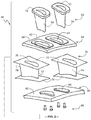
- FIG. 2 is an exploded view of a turbine nozzle, according to one aspect of the present disclosure
- FIG. 3 is a schematic depiction of components used in the assembly of an airfoil preform, according to one aspect of the present disclosure
- FIG. 4 is a schematic overhead plan view of a core preform, according to the present disclosure.
- FIG. 5 is a schematic overhead plan view of a trailing edge preform, according to the present disclosure.
- FIG. 6 is a schematic overhead plan view of the core and trailing edge preform of FIGS. 4 and 5 , around which an exemplary pair of composite wrap plies are wrapped;
- FIG. 7 is a schematic depiction of a 0-degree ply and a 90-degree ply, prior to stacking as a composite wrap ply;
- FIG. 8 is a schematic depiction of a composite wrap ply, which is assembled using the 0-degree ply and the 90-degree ply of FIG. 7 ;
- FIG. 9 is a perspective view of a portion of an exemplary airfoil preform, illustrating initial steps performed during the fabrication of the airfoil preform of FIG. 3 ;
- FIG. 10 is a schematic cross-sectional view of a portion of the airfoil preform of FIG. 3 ;
- FIG. 11 is a schematic cross-sectional view of a portion of a ceramic matrix composite nozzle preform of FIG. 2 ;
- FIGS. 12A and 12B are flowcharts describing a process for manufacturing the present ceramic matrix composite nozzle preform.
- the “A” axis represents an axial orientation.
- the terms “axial” and/or “axially” refer to the relative position/direction of objects along axis A, which is substantially parallel with the axis of rotation of the gas turbine system.
- the terms “axial” and/or “axially” refer to the relative position/direction of objects along an axis A, which extends along the length of the part through its centerline (as shown in FIG. 3 ).
- radial and/or radially refer to the relative position or direction of objects along an axis “R”, which intersects axis A at only one location.
- axis R is substantially perpendicular to axis A.
- circumferential refers to movement or position around axis A (e.g., axis “C”).
- the term “circumferential” may refer to a dimension extending around a center of a respective object (e.g., a rotor or a longitudinal axis of a part).
- FIG. 1 schematically illustrates an exemplary gas turbine 10 .
- the gas turbine 10 generally includes an inlet section 12 , a compressor section 14 disposed downstream of the inlet section 12 , a combustion section 16 disposed downstream of the compressor section 14 , a turbine section 18 disposed downstream of the combustion section 16 , and an exhaust section 20 disposed downstream of the turbine section 18 .
- the gas turbine 10 may include one or more shafts 22 (also known as “rotors”) that couple the compressor section 14 to the turbine section 18 .
- the shaft 22 is coaxial with the longitudinal axis of the gas turbine 10 and, specifically, the turbine section 18 .
- air 24 flows through the inlet section 12 and into the compressor section 14 , where the air 24 is progressively compressed, thus providing compressed air 26 to the combustion section 16 .
- At least a portion of the compressed air 26 is mixed with a fuel 28 within one or more combustors in the combustion section 16 and burned to produce combustion gases 30 .
- the combustion gases 30 flow from the combustion section 16 to into the turbine section 18 , where thermal and/or kinetic energy are transferred from the combustion gases 30 to rotor blades (not shown) attached to the shaft 22 , thereby causing the shaft 22 to rotate.
- the mechanical rotational energy may then be used for various purposes, such as to power the compressor section 14 and/or to generate electricity, via a generator 21 coupled to the shaft 22 .
- the combustion gases 30 exiting the turbine section 18 may then be exhausted from the gas turbine 10 , via the exhaust section 20 .
- each row of rotor blades has a corresponding row of stationary nozzles 40 that are positioned between and that are attached to an outer side wall 60 and an inner side wall 80 .
- a row of the rotor blades and the adjacent stationary nozzles define a turbine stage.
- the length of the rotor blades and stationary nozzles increases with each stage, and many heavy-duty gas turbines 10 used for power generation have three or four turbine stages.
- Gas turbines 10 are routinely operated at very high temperatures (e.g., with combustion gas temperatures in excess of 2,200° F., as the gases enter the turbine section 18 ). Such high temperatures require turbine blades and nozzles to be cooled to prevent component stress or failure. The amount of air diverted to the turbine section 18 for cooling the blades and nozzles 40 negatively impacts the efficiency of the gas turbine 10 .
- some gas turbine manufacturers have contemplated using ceramic matrix composite (CMC) materials to create the blades and/or nozzles of one or more turbine stages.
- CMC ceramic matrix composite
- the blades and/or nozzles at the inlet end of the turbine section 18 which are exposed to higher temperatures, may be made of CMC materials.
- each turbine nozzle 40 is installed in a generally radial direction through an outer side wall 60 that circumscribes the interior of the turbine section 18 (a portion of which is shown in FIG. 2 ).
- the radially inner ends of the turbine nozzles 40 are secured to a circumferential inner side wall 80 (a portion of which is shown in FIG. 2 ).
- the inner and outer side walls 80 , 60 are radially spaced apart from one another in a given turbine stage and define a portion of the hot gas path between the inner and outer side walls 80 , 60 .
- Each turbine nozzle 40 includes a metal (e.g., superalloy) spar 50 that serves as the foundation of the nozzle 40 .
- the metal spar 50 includes a mounting flange 52 and a hollow airfoil-shaped body 54 extending from the mounting flange 52 .
- the metal spar 50 is installed through an opening 64 in the outer side wall 60 , which corresponds in size and shape to the airfoil-shaped body 54 of the metal spar 50 .
- the opening 64 is surrounded by a mounting ledge 62 that projects radially outward from a surface 66 of the outer side wall 60 .
- the mounting flange 52 of the metal spar 50 is in contact with the mounting ledge 62 and is secured to the mounting ledge 62 using removable mechanical fasteners, such as bolts (not shown).
- a CMC nozzle shell 70 is positioned over the airfoil-shaped body 54 of the metal spar 50 .
- the CMC nozzle shell 70 includes a primary outer nozzle platform 72 , a primary inner nozzle platform 76 , and an airfoil-shaped body 74 extending radially between the primary inner nozzle platform 76 and the primary outer nozzle platform 72 .
- the airfoil-shaped body 74 is hollow or substantially hollow to receive a flow of cooling air.
- a cavity 75 which is sized and shaped to accommodate the airfoil-shaped body 54 of the metal spar 50 , extends through the airfoil-shaped body 74 from the primary outer nozzle platform 72 to the primary inner nozzle platform 76 .
- the airfoil-shaped body 74 includes a leading edge 77 and a trailing edge 78 .
- the inner side wall 80 includes a surface 82 that circumscribes the interior of the turbine section and a plurality of airfoil-shaped extensions 84 that project radially outward from the surface 82 .
- Each airfoil-shaped extension 84 is sized and shaped to fit within the cavity 75 of a corresponding CMC nozzle shell 70 .
- Mechanical fasteners 90 are used to secure the inner side wall 80 to the metal spar 50 , capturing the CMC nozzle shell 70 between the outer side wall 60 and the inner side wall 80 .
- the process of manufacturing a ceramic matrix composite nozzle shell 70 has typically involved integrating the airfoil-shaped body 74 with the primary inner nozzle platform 76 and the primary outer nozzle platform 72 , as one piece during the manufacturing process, much like conventional investment casting techniques used to make metal vanes.
- the detailed geometry of the nozzle shell 70 and the need to reduce stress at the joints between the body 74 and the primary nozzle platforms 72 , 76 pose challenges to designing, manufacturing, and integrating CMC components into an affordable, producible design for turbine applications.
- CMC nozzle shells are the method known as the melt infiltration (MI) process.
- MI melt infiltration
- CMCs are produced using “prepreg” plies comprising silicon carbide (SiC)-containing fibers, each prepreg ply being in the form of a tape-like structure including the desired reinforcement material, a precursor of the CMC matrix material, and one or more binders.
- SiC silicon carbide
- ply it should be understood as describing a prepreg, fiber-reinforced ply unless otherwise indicated.
- sicon carbide-containing fiber refers to a fiber having a composition that includes silicon carbide and preferably is substantially silicon carbine.
- the fiber may have a silicon carbide core surrounded with carbon or, in the reverse, may have a carbon core surrounded by or encapsulated with silicon carbide.
- the “matrix ply” refers to a tape-like structure made of a precursor of the CMC matrix material and one or more binders, which omits the fiber reinforcement materials.
- Two prepreg plies may be used to produce a composite ply 110 (as shown in FIGS. 3, 7, and 8 ), in which one ply 112 has unidirectional fibers oriented in a first direction (e.g., at 0-degrees, which is parallel to the longitudinal axis of the nozzle shell 70 ) and one ply 114 has unidirectional fibers oriented in a second direction transverse to the first direction (e.g., at 90-degrees, which is perpendicular to the 0-degree fibers).
- a first direction e.g., at 0-degrees, which is parallel to the longitudinal axis of the nozzle shell 70
- one ply 114 has unidirectional fibers oriented in a second direction transverse to the first direction (e.g., at 90-degrees, which is perpendicular to the 0-degree fibers).
- the composite ply 110 may include plies 111 containing fibers with other orientations, such as plies having fibers with an orientation of from +30 degrees to ⁇ 30 degrees relative to the 0-degree fibers in the 0-degree ply 112 .
- FIG. 3 illustrates the CMC nozzle shell 70 and the components used to produce the airfoil-shaped body preform 74 , according to one aspect of the present disclosure.
- the CMC nozzle shell 70 includes a primary outer nozzle platform 72 , a primary inner nozzle platform 76 , and the airfoil-shaped body preform 74 extending therebetween.
- the airfoil-shaped body preform 74 includes a first (outer) set of platform plies 100 , which are labeled individually as outer platform ply 100 a , 100 b , 100 n ; a set of composite wrap plies 110 , one of which is illustrated as including a 0-degree ply 112 , a 90-degree ply 114 , and an optional third ply 111 having fibers at an orientation other than 0-degrees and 90-degrees; and a second (inner) set of platform plies 120 , which are labeled individually as inner platform ply 120 a , 120 b , . . . 120 n .
- the outer platform plies 100 define a secondary outer nozzle platform 172
- the inner platform plies 120 define a secondary inner nozzle platform 176 (as shown in FIG. 10 ).
- the outer platform plies 100 define an opening 102 therethrough that corresponds to the size and shape of the cavity 75 .
- the inner platform plies define an opening 122 therethrough that corresponds to the size and shape of the cavity 75 .
- Various numbers of plies 100 , 110 , and 120 may be used to produce the airfoil body preform 74 , which includes the integrated secondary outer nozzle platform 172 and the integrated secondary inner nozzle platform 176 .
- the number of composite wrap plies in the set of composite plies 110 may vary, according to design needs.
- One exemplary range of composite plies 110 may be from five plies to twenty-five plies.
- the number “n” of platform plies 100 , 120 may vary, according to design needs, but may be in the range of three to ten in each of the secondary outer nozzle platform 172 and the secondary inner nozzle platform 176 .
- the number of inner platform plies 120 in the secondary inner nozzle platform 176 is equal to the number of outer platform plies 100 in the secondary outer nozzle platform 172 .
- the number of platform plies 100 , 120 is supplemental to the number of platform plies in the primary outer nozzle platform 72 and the primary inner nozzle platform 76 (shown in more detail in FIG. 11 ).
- the airfoil-shaped body preform 74 further includes an interior preform 160 , as shown in FIG. 6 .
- a core preform 138 is defined by a set of core plies 140 , which are wrapped circumferentially about a tool or mold 145 to define the interior cavity 75 of the CMC nozzle shell 70 (as shown in FIG. 6 ).
- the tool 145 has a wider end 147 that corresponds to the leading edge 77 of the airfoil-shaped body 74 and a narrower end 148 that interfaces with a trailing edge insert 180 (shown in FIG. 5 ).
- the innermost core ply 141 is a reinforcement-free matrix ply, while the remaining core plies 140 are fiber-reinforced.
- the seams of the core plies 140 may be staggered to achieve an approximately uniform thickness around the perimeter of the cavity 75 .
- the trailing edge insert 180 is positioned at the narrower end of the core plies 140 to supplement the desired airfoil shape.
- the trailing edge insert 180 includes a number of fiber-reinforced plies 182 that are stacked in such a way as to define a V-shaped cross-sectional profile.
- the plies 182 forming the trailing edge insert 180 may be stacked with alternating fiber orientations, if so desired. After stacking, the trailing edge insert 180 may be subjected to hot de-bulking and green-machining, as described further herein.
- the composite wrap plies 110 are wrapped circumferentially around the core plies 140 and the trailing edge insert 180 from the trailing edge ( 78 ) of the airfoil-shaped preform 74 on the pressure (concave) side to the trailing edge 78 of the preform 74 on the suction (convex) side (or vice versa).
- FIG. 6 illustrates two exemplary composite wrap plies 110 , although it should be understood that more than two composite wrap plies 110 are typically used.
- Each composite wrap ply 110 includes at least one 0-degree ply 112 and at least one 90-degree ply 114 .
- the outermost surface of the airfoil body preform 74 is produced by one or more matrix plies 150 (shown in FIG. 10 ), which include the suitable precursor of the desired ceramic matrix material but which exclude the reinforcement fibers found in the core plies 140 and the composite wrap plies 110 .
- the reinforcement-free matrix ply (plies) 150 protect the reinforcement fibers at the surfaces of the airfoil preform 74 during the completion of the fabrication process.
- the composite plies 110 include a 0-degree ply 112 and a 90-degree ply 114 , each of which is generally rectangular with a length 212 and a width 222 , 274 , respectively, that is less than the length 212 .
- the 0-degree ply 112 has an outer longitudinal edge 142 and an inner longitudinal edge 146 , and the width 222 is defined between the longitudinal edges 142 , 146 .
- the 90-degree ply 114 has an outer longitudinal edge 152 and an inner longitudinal edge 156 , and the width 274 is defined between the longitudinal edges 152 , 156 .
- each 0-degree ply 112 is greater than a height 174 of the airfoil-shaped body preform 74 (shown in FIG. 3 ) and is greater than the width 274 of each 90-degree ply 114 .
- the width 274 of each 90-degree ply 114 is also greater than the height 174 of the airfoil-shaped body preform 74 but may be less than the width 222 of the 0-degree ply 112 .
- the width 222 of the 0-degree plies 112 used in the composite plies 110 may vary—that is, the 0-degree plies 112 that are radially disposed closer to the longitudinal axis 170 of the airfoil-shaped body preform 74 may be wider than the 0-degree plies 112 that are radially disposed toward the outer surface of the preform 74 .
- the longitudinal edges 142 , 146 of the 0-degree ply 112 and the longitudinal edges 152 , 156 of the 90-degree ply 114 are cut according to a prescribed pattern.
- the cuts to the 0-degree ply 112 and the 90-degree ply 114 produce ply fingers 118 , 158 that are folded in composite layers in a direction substantially perpendicular to and away from the longitudinal axis 170 of the airfoil-shaped preform 74 to form a perimeter around the cavity 75 with little to no overlap of adjacent fingers 118 in each individual composite ply 110 .
- a center panel 113 of the 0-degree ply 112 is disposed between the longitudinal edge 142 and the longitudinal edge 146 with enough margin to produce the fingers 118 having the desired width.
- the 90-degree ply 114 with its pre-cut fingers 158 may be stacked with the 0-degree ply 112 with its pre-cut fingers 118 , such that a center portion of the 90-degree ply 114 is aligned with the center panel 113 of the 0-degree ply 112 , to define the composite wrap ply 110 .
- Paper or foil strips may be used to separate the cut fingers 118 , 158 of one composite wrap ply 110 from each other and/or from the cut fingers 118 , 158 of an adjacent composite wrap ply 110 , until such time as the fingers 118 , 158 are laid down.
- the composite wrap plies 110 (one of which is shown as composite wrap ply 110 a in FIG. 9 ) have longitudinal edges (e.g., 142 , 152 ) that extend beyond the airfoil-shaped body 74 and that are cut into fingers 118 , 158 that are incorporated into a secondary outer nozzle platform 172 and a secondary inner nozzle platform 176 of the airfoil-shaped preform 74 (as shown in FIG. 10 ).
- the composite ply 110 a wraps around the core plies 140 (shown in FIG.
- the fingers 118 a , 158 a of the composite ply 110 a are folded down, there may be some areas at the corners of the outer platform ply 100 a that are not covered by the fingers 118 a , 158 a . In these areas, it is desirable to include filler panels 130 to create a layer of uniform thickness before the application of the subsequent outer platform ply 100 b and the folding down of the fingers 118 , 158 of another 0-degree ply 112 (e.g., 112 b , not shown in this Figure).
- the filler panels 130 may be made of the removed material 116 a or from additional fiber-reinforced plies having the same or different fiber orientation as the 0-degree ply 112 a.
- the outer platform ply 100 a may have the same or different fiber orientation as the outer platform ply 100 b .
- the outer platform ply 100 a may have fibers oriented at 0-degrees, while the outer platform ply 100 b may have fibers oriented at 90-degrees (or some other non-zero angle).
- the fiber orientation of the outer platform plies 100 may vary from layer to layer.
- a single outer platform ply 100 is illustrated for insertion between the folded fingers 118 , 158 of the composite wrap plies 110 , it should be understood that different numbers (e.g., two or more) of outer platform plies 100 may be inserted together between the folded fingers 118 , 158 of the composite wrap plies 110 , as desired.
- the folding of the fingers 118 , 158 of the composite wrap plies 110 is described as involving the folding of the 0-degree fingers 118 and the 90-degree fingers 158 in unison, such that the fingers 118 , 158 of a single composite wrap ply 110 are disposed between adjacent platform plies 100 (or 120 ).
- the 0-degree fingers 118 and the 90-degree fingers 158 of an individual composite wrap ply 110 may be separated by an intermediately positioned platform ply 100 (or 120 ), if so desired.
- the number of platform plies 100 , 120 would be greater than the number of platform plies 100 , 120 used in the embodiment in which the fingers 118 , 158 of each composite ply 110 are folded at the same time.
- FIG. 10 A cross-section of a portion of the airfoil-shaped body preform 74 is shown in FIG. 10 .
- the core wraps 140 are disposed radially outward of the longitudinal axis 170 of the airfoil-shaped body preform 74 .
- the body includes alternating composite wrap plies 110 (made of 90-degree plies 114 and 0-degree plies 112 ) (e.g., 110 a , 110 b , 110 c ) whose longitudinal edges 142 , 152 have been cut into fingers 118 , 158 that are folded in a transverse direction relative to the longitudinal axis 170 .
- outer platform plies 100 e.g., 100 a , 100 b , 100 c
- secondary outer nozzle platform 172 that is integral with the airfoil-shaped body 74 .
- the fingers 118 , 158 and any necessary filler panels 130 are interleaved between the inner platform plies 120 (e.g., 120 a , 120 b , 120 c ) to form a secondary inner nozzle platform 176 that is integral with the airfoil-shaped body 74 opposite the secondary outer nozzle platform 172 .
- a reinforcement-free matrix ply 150 forms a smooth surface on the exterior of the airfoil-shaped body preform 74 .
- the plies 112 , 114 As the plies 112 , 114 are applied to the tool, the plies 112 , 114 produce concave fillets (not shown) that form a rounded angle between the airfoil-shaped body 74 and each of the secondary outer nozzle platform 172 and the secondary inner nozzle platform 176 .
- additional fiber-reinforcement plies may be rolled up into a long “noodle” and wrapped circumferentially about the perimeter of the airfoil-shaped body preform 74 , such that the rolled-up “noodle” plies are disposed within the voids between the composite wrap plies 110 and the platform plies 100 , 120 or in any other void locations.
- the 90-degree plies are truncated and do not fold over for incorporation into the secondary nozzle platforms. Rather, only the 0-degree plies are used as reinforcement layers in the joints between the airfoil portion and the platform portions of the airfoil-shaped body preform. As a result, the resulting CMC nozzle shell may be prone to weakness and cracking at the joints.
- the present embodiments described herein fold and interleave with the platform plies 100 , 120 both the 0-degree plies 112 and the 90-degree plies 114 , thereby reinforcing the joints of the airfoil-shaped body preform 74 and the subsequent CMC nozzle shell 70 .
- FIG. 11 illustrates a partial cross-section of the CMC nozzle shell 70 , in which the primary outer nozzle platform 72 and the primary inner nozzle platform 76 are joined to the airfoil-shaped body preform 74 with its integral secondary outer nozzle platform 172 and integral secondary inner nozzle platform 176 .
- the primary outer nozzle platform 72 and the primary inner nozzle platform 76 each are formed from a stacked set of fiber-reinforced platform plies 202 , 204 .
- Each platform ply 202 , 204 includes an opening therein that surrounds the cavity 75 of the CMC nozzle shell 70 (similar to the outer platform ply 100 and the inner platform ply 120 ).
- the primary outer nozzle platform 72 may have the same number of platform plies 202 , 204 as the primary inner nozzle platform 76 . In one embodiment, a total of between 10 and 20 platform plies are used for each of the outer nozzle platform 72 and the inner nozzle platform 76 , which includes any combination of plies 202 (reinforced with fibers in a first direction) and plies 204 (reinforced with fibers in a second, transverse direction).
- the platform plies 202 may have a first fiber orientation, while the platform plies 204 may have a second fiber orientation transverse to the first fiber orientation.
- the platform plies 202 and the platform plies 204 may have fibers that are disposed at a 90-degree offset from one another.
- the platform plies 202 , 204 may be arranged in alternating fashion or in a pattern-wise arrangement.
- the primary outer nozzle platform 72 and the primary inner nozzle platform 76 are subjected to de-bulking and green machining after the respective platform plies 202 , 204 are stacked.
- FIGS. 12A and 12B define a process 300 for manufacturing the components of the CMC nozzle shell 70 and assembling the CMC nozzle shell 70 , according to the present disclosure.
- one or more matrix plies 150 are circumferentially disposed around a tool (not shown) that defines the outer shape of the CMC nozzle shell 70 .
- the matrix plies 150 may define one or more layers that provide a smooth protective surface over the fiber-reinforced composite plies 110 , the outer platform plies 100 , and the inner platform plies 120 .
- Step 320 defines the production of several preform structures used to produce the CMC nozzle shell 70 , including the trailing edge preform 180 , the inner nozzle platform preform 76 , and the outer nozzle platform preform 72 .
- the trailing edge (TE) preform 180 (shown in FIG. 5 ) is assembled, which will be incorporated as part of a core and trailing edge preform 160 (see FIG. 6 ).
- the trailing edge plies 182 may be stacked together to define a V-shaped trailing edge preform 180 that is coupled to the core plies 140 .
- the stacked trailing edge plies 182 may be subjected to de-bulking and green machining before being coupled with the core plies 140 .
- the inner nozzle platform 76 is produced by stacking a plurality of platform plies 202 , 204 on one another.
- the platform plies 202 , 204 may be unidirectional fiber reinforced plies, and the fiber orientation of the platform plies 202 may be transverse to the fiber orientation of the platform plies 204 .
- the fibers in the platform plies 202 may be perpendicular to the fibers in the platform plies 204 .
- the platform plies 202 , 204 may be stacked in an alternating pattern (e.g., 202 - 204 - 202 - 204 , etc.) or may be stacked in some other pattern (e.g., 202 - 202 - 204 - 202 - 202 - 204 , etc.).
- the outer nozzle platform 72 is produced by stacking a plurality of platform plies 202 , 204 on one another.
- the platform plies 202 , 204 may be unidirectional fiber reinforced plies, and the fiber orientation of the platform plies 202 may be transverse to the fiber orientation of the platform plies 204 .
- the fibers in the platform plies 202 may be perpendicular to the fibers in the platform plies 204 .
- the platform plies 202 , 204 may be stacked in an alternating pattern (e.g., 202 - 204 - 202 - 204 , etc.) or may be stacked in some other pattern (e.g., 202 - 202 - 204 - 202 - 202 - 204 , etc.).
- the stacked plies 202 , 204 may be subjected to de-bulking and “green-machining” in which the plies 202 , 204 are machined to a close-to-desired final shape.
- Green-machining may include cutting, milling, and grinding, as is known in the art. It is easier to machine the platforms 72 , 76 in a “green” state prior to rigidizing and densifying.
- Steps 310 , 322 , 324 , and 326 may be performed in any order.
- these steps 310 , 322 , 324 , and 326 may be performed simultaneously to reduce manufacturing time.
- the core plies 140 are circumferentially wrapped around a tool 145 (shown in FIG. 4 ) to define the cavity 75 of the CMC nozzle shell 70 .
- the core plies 140 may be staggered, so that the edges of each ply 140 are circumferentially offset from one another, thereby providing a uniform thickness around the cavity 75 .
- the innermost core ply 140 may be a fiber-less matrix ply.
- the trailing edge insert 180 is aligned with the narrow end of the tool 145 and wrapped core plies 140 , thereby forming a core and trailing edge preform 160 .
- Step 340 results in the production of the airfoil-shaped body 74 with its integral outer and inner nozzle platforms 172 , 176 .
- composite wrap plies 110 which include 0-degree plies 112 and 90-degree (or transverse) plies 114 , are circumferentially wrapped around the core and trailing edge preform 160 to define the body of the airfoil-shaped body preform 74 .
- the composite wrap plies 110 are applied in a manner to produce an alternating arrangement of 0-degree plies 112 and 90-degree (or transverse) plies 114 .
- the longitudinal edges 142 , 146 of the 0-degree plies 112 and the longitudinal edges 152 , 156 of the 90-degree plies 114 are pre-cut according to a predetermined pattern to produce fingers 118 , 158 that are interleaved with platform plies 120 to form the integral inner nozzle platform 176 (step 344 ) and that are interleaved with platform plies 100 to form the integral outer nozzle platform 172 (step 346 ).
- areas of the platform plies 100 or 120 not covered by the fingers 118 , 158 when folded away from the core plies 140 , may be covered with filler panels 130 . Steps 344 and 346 may be performed in either order.
- the airfoil-shaped body preform 74 may be de-bulked and/or green-machined, if desired, before step 350 .
- step 350 the airfoil-shaped body preform 74 is joined to the outer nozzle platform 72 (formed in step 326 ) and the inner nozzle platform 76 (formed in step 324 ).
- step 352 the outer nozzle platform 72 is joined to the integral outer nozzle platform 172 of the airfoil-shaped body preform 74 .
- step 354 the inner nozzle platform 76 is joined to the integral inner nozzle platform 176 of the airfoil-shaped body preform 74 . Steps 352 and 354 may be performed in either order.
- Caul sheets (not shown) or other known tool components for rigidizing processes can then be applied to the surfaces of the non-rigidized CMC nozzle shell 70 in preparation for rigidizing (step 360 ).
- the caul sheets are rubbery and expand at a higher rate than rigid tooling, making the caul sheets useful to apply pressure during an autoclave cycle.
- the caul sheets provide compaction force for the composite component in areas that are blocked by rigid tooling and permit formation of a densified composite having a desired geometry.
- non-rigidized (and grammatical equivalents thereof) describes objects that have not been rigidized at all or, at a minimum, have been partially rigidized to a point that the rigidizing is insubstantial.
- the non-rigidized vane preform can be rigidized to compact and set the plasticizers in the prepreg plies (step 370 ).
- the components may be rigidized in an autoclave at elevated temperatures and pressures. While not so limited, the components may be rigidized at temperatures from about 200° C. to about 400° C. and at pressures from about 50 psig to about 300 psig. Additionally, or alternatively, rigidizing can include curing (e.g., by heating), compression molding, bladder molding, or other suitable methods of hardening the CMC nozzle shell 70 .
- partially rigidizing includes rigidizing to a detectable point but not rigidizing to a fully rigidized point.
- fully rigidized includes rigidizing to a point for which an object is rigidized to a desired end point.
- the rigidizing terms form a hierarchy with some overlap between proximate terms. For example, the terms non-rigidized, partially rigidized, and fully rigidized express increasing amount of rigidizing (with some overlap).
- co-rigidizing includes rigidizing at substantially the same time or, at a minimum, an overlapping period during which two objects are rigidized. Co-rigidizing can produce a substantially continuous matrix phase with additional strength believed (although not intended to be limited by theory) to be provided by increased bonding between the airfoil 74 , the outer nozzle platform 72 , and the inner nozzle platform 76 .
- the preform including the airfoil body 74 , the outer nozzle platform 72 , and the inner nozzle platform 76 may be co-rigidized with an initial partial rigidizing followed by a subsequent rigidizing. In all embodiments, when rigidizing is substantially complete, a rigidized vane preform is formed.
- the components may be subjected to a burn-out, or off-gassing, step (not separately included in the flowchart).
- the organic components such as plasticizers, are converted to carbon.
- the rigidized vane preform is densified (step 380 ) in one or more steps.
- the vane preform can be partially densified by introducing a carbon-containing slurry (as is known in the art) into the porosity of the rigidized vane preform, and can be further densified with at least silicon, and alternatively boron doped silicon, through a melt infiltration process (as known in the art) to form the finished CMC nozzle shell 70 .
- components include polymer infiltration and pyrolysis (“PIP”).
- PIP polymer infiltration and pyrolysis
- silicon carbide fiber preforms are infiltrated with a pre-ceramic polymer, such as polysilazane and then heat-treated to form a SiC matrix.
- the components may include an oxide/oxide process.
- aluminum or alumino-silicate fibers may be prepregged and then laminated into a preselected geometry and subsequently heated to form the ceramic matrix.
- Components may also be fabricated from a carbon fiber reinforced silicon carbide matrix (C/SiC) CMC.
- the C/SiC processing includes laying up a carbon fibrous preform in the preselected geometry.
- the tool may be made of a graphite material.
- the fibrous preform is supported by the tooling during a chemical vapor infiltration process at about 1200° C., whereby the C/SiC CMC component is formed.
- the CMC nozzle shell 70 can be machined (step 390 ) to provide the desired final geometry.
- the outer wall and inner nozzle platforms 72 , 76 can include SiC-coated fibers and a polymer-based matrix. Materials such as a low melt alloy, machining wax, and/or polymeric materials can be used to encapsulate the platforms 72 , 76 , if desired.
- the CMC nozzle shell 70 may be cooled with water during machining.
- the cutting and/or grinding direction may be predetermined to avoid tearing out fibrous materials. Cutting and/or grinding speeds may also be predetermined to avoid damage to CMC nozzle shell 70 in the form of delamination or removal of fibers at the surface.
- Exemplary embodiments of the present CMC nozzle shell and processes for manufacturing a CMC nozzle are described above in detail.
- the methods and components described herein are not limited to the specific embodiments described herein, but rather, aspects of the methods and components may be utilized independently and separately from other components described herein.
- the methods and components described herein may have other applications not limited to practice with turbine nozzles for power-generating gas turbines, as described herein. Rather, the methods and components described herein can be implemented and utilized in various other industries.
Landscapes
- Engineering & Computer Science (AREA)
- Chemical & Material Sciences (AREA)
- Ceramic Engineering (AREA)
- Materials Engineering (AREA)
- Manufacturing & Machinery (AREA)
- Structural Engineering (AREA)
- Organic Chemistry (AREA)
- General Engineering & Computer Science (AREA)
- Mechanical Engineering (AREA)
- Inorganic Chemistry (AREA)
- Composite Materials (AREA)
- Chemical Kinetics & Catalysis (AREA)
- Turbine Rotor Nozzle Sealing (AREA)
Abstract
Description
Claims (17)
Priority Applications (1)
| Application Number | Priority Date | Filing Date | Title |
|---|---|---|---|
| US16/170,794 US11035239B2 (en) | 2018-10-25 | 2018-10-25 | Ceramic matrix composite turbine nozzle shell and method of assembly |
Applications Claiming Priority (1)
| Application Number | Priority Date | Filing Date | Title |
|---|---|---|---|
| US16/170,794 US11035239B2 (en) | 2018-10-25 | 2018-10-25 | Ceramic matrix composite turbine nozzle shell and method of assembly |
Publications (2)
| Publication Number | Publication Date |
|---|---|
| US20200131919A1 US20200131919A1 (en) | 2020-04-30 |
| US11035239B2 true US11035239B2 (en) | 2021-06-15 |
Family
ID=70328493
Family Applications (1)
| Application Number | Title | Priority Date | Filing Date |
|---|---|---|---|
| US16/170,794 Active 2039-05-11 US11035239B2 (en) | 2018-10-25 | 2018-10-25 | Ceramic matrix composite turbine nozzle shell and method of assembly |
Country Status (1)
| Country | Link |
|---|---|
| US (1) | US11035239B2 (en) |
Cited By (4)
| Publication number | Priority date | Publication date | Assignee | Title |
|---|---|---|---|---|
| US11560800B1 (en) | 2021-11-12 | 2023-01-24 | Raytheon Technologies Corporation | Airfoil with fiber plies having interdigitated fingers in trailing end |
| US11732589B1 (en) | 2022-07-15 | 2023-08-22 | Raytheon Technologies Corporation | Airfoil vane multiplet with interleaved fiber plies |
| US11781435B2 (en) | 2022-02-28 | 2023-10-10 | Rtx Corporation | Bifurcated fabric architecture for airfoils, methods of manufacture thereof and airfoils comprising the same |
| US12326100B1 (en) | 2024-01-31 | 2025-06-10 | Rtx Corporation | Gas turbine engine component fillets formed of CMC plies |
Families Citing this family (3)
| Publication number | Priority date | Publication date | Assignee | Title |
|---|---|---|---|---|
| FR3112142B1 (en) | 2020-07-03 | 2022-09-09 | Safran Ceram | Process for manufacturing a nozzle vane made of composite material with a ceramic matrix |
| FR3114348B1 (en) * | 2020-09-23 | 2022-09-16 | Safran Aircraft Engines | Turbomachine turbine with CMC distributor with force take-up |
| US11591921B1 (en) * | 2021-11-05 | 2023-02-28 | Rolls-Royce Plc | Ceramic matrix composite vane assembly |
Citations (30)
| Publication number | Priority date | Publication date | Assignee | Title |
|---|---|---|---|---|
| US4564543A (en) | 1984-01-03 | 1986-01-14 | The Boeing Company | Multiple lap-joint for thermoplastic laminates |
| US4966527A (en) * | 1988-08-03 | 1990-10-30 | Mtu Motoren-Und Turbinen-Union Muenchen Gmbh | Composite blade construction for a propeller or rotor blade |
| US4992317A (en) * | 1988-12-22 | 1991-02-12 | Xerkon, Inc. | Reinforced three dimensional composite parts of complex shape and method of making |
| US5429853A (en) | 1992-02-11 | 1995-07-04 | Societe Nationale Industrielle Et Aerospatiale | Method for producing a fiber reinforcement for a component of composite material, and composite component comprising such a reinforcement |
| US5630700A (en) | 1996-04-26 | 1997-05-20 | General Electric Company | Floating vane turbine nozzle |
| US20020064456A1 (en) * | 2000-11-28 | 2002-05-30 | Snecma Moteurs | Assembly formed by at least one blade and a blade-fixing platform for a turbomachine, and a method of manufacturing it |
| US6709230B2 (en) | 2002-05-31 | 2004-03-23 | Siemens Westinghouse Power Corporation | Ceramic matrix composite gas turbine vane |
| US7028462B2 (en) | 2003-11-07 | 2006-04-18 | General Electric Company | Method and apparatus for arresting a crack within a body |
| US7198472B2 (en) * | 2004-12-10 | 2007-04-03 | Rolls-Royce Plc | Platform mounted components |
| US7510379B2 (en) | 2005-12-22 | 2009-03-31 | General Electric Company | Composite blading member and method for making |
| US8206096B2 (en) | 2009-07-08 | 2012-06-26 | General Electric Company | Composite turbine nozzle |
| US20130004331A1 (en) * | 2011-06-29 | 2013-01-03 | Beeck Alexander R | Turbine blade or vane with separate endwall |
| US20130251939A1 (en) * | 2012-03-23 | 2013-09-26 | General Electric Company | Process for producing ceramic composite components |
| US8714932B2 (en) | 2008-12-31 | 2014-05-06 | General Electric Company | Ceramic matrix composite blade having integral platform structures and methods of fabrication |
| US20140199174A1 (en) | 2013-01-11 | 2014-07-17 | General Electric Company | Method of forming a ceramic matrix composite component, a ceramic matrix composite component and a tip member |
| US20140271208A1 (en) * | 2013-03-15 | 2014-09-18 | General Electric Company | Systems and method for a composite blade with fillet transition |
| US20140349538A1 (en) * | 2011-12-14 | 2014-11-27 | Snecma | Fiber structure woven as a single piece by 3d weaving and application to the manufacturing of composite material part |
| US9151166B2 (en) | 2010-06-07 | 2015-10-06 | Rolls-Royce North American Technologies, Inc. | Composite gas turbine engine component |
| US20160230568A1 (en) * | 2015-02-05 | 2016-08-11 | Rolls-Royce Corporation | Ceramic matrix composite gas turbine engine blade |
| US20160245103A1 (en) * | 2012-11-13 | 2016-08-25 | Snecma | Monobloc preform and blade for turbo machine |
| US20170058912A1 (en) * | 2015-04-29 | 2017-03-02 | Snecma | Blade provided with platforms possessing attachment portions |
| US9708918B2 (en) | 2011-12-01 | 2017-07-18 | Herakles | Hollow-blade turbine vane made from composite material, turbine or compressor including a nozzle or guide vane assembly formed by such blades, and turbomachine comprising same |
| US9752445B2 (en) | 2012-04-10 | 2017-09-05 | Ihi Corporation | Method for producing coupled turbine vanes, and turbine vanes |
| US20170326757A1 (en) * | 2014-10-30 | 2017-11-16 | Safran Aircraft Engines | Composite blade comprising a platform equipped with a stiffener |
| US20180010462A1 (en) * | 2016-07-05 | 2018-01-11 | Safran Aircraft Engines | Fitted platform for a turbine engine fan, and a method of fabricating it |
| US20180036914A1 (en) * | 2015-02-16 | 2018-02-08 | Safran Aircraft Engines | Method for manufacturing a turbomachine blade made of composite material |
| US20180135436A1 (en) * | 2015-04-29 | 2018-05-17 | Safran Aircraft Engines | Blade having platforms including inserts |
| US9981438B2 (en) | 2012-04-13 | 2018-05-29 | General Electric Company | Pre-form ceramic matrix composite cavity and a ceramic matrix composite component |
| US20180230823A1 (en) | 2016-10-28 | 2018-08-16 | Rolls-Royce Corporation | Turbine blade with ceramic matrix composite material construction |
| US20180319101A1 (en) * | 2015-11-06 | 2018-11-08 | Safran | A method of fabricating a composite material part having a body integral with one or more platforms |
-
2018
- 2018-10-25 US US16/170,794 patent/US11035239B2/en active Active
Patent Citations (33)
| Publication number | Priority date | Publication date | Assignee | Title |
|---|---|---|---|---|
| US4564543A (en) | 1984-01-03 | 1986-01-14 | The Boeing Company | Multiple lap-joint for thermoplastic laminates |
| US4966527A (en) * | 1988-08-03 | 1990-10-30 | Mtu Motoren-Und Turbinen-Union Muenchen Gmbh | Composite blade construction for a propeller or rotor blade |
| US4992317A (en) * | 1988-12-22 | 1991-02-12 | Xerkon, Inc. | Reinforced three dimensional composite parts of complex shape and method of making |
| US5429853A (en) | 1992-02-11 | 1995-07-04 | Societe Nationale Industrielle Et Aerospatiale | Method for producing a fiber reinforcement for a component of composite material, and composite component comprising such a reinforcement |
| US5630700A (en) | 1996-04-26 | 1997-05-20 | General Electric Company | Floating vane turbine nozzle |
| US20020064456A1 (en) * | 2000-11-28 | 2002-05-30 | Snecma Moteurs | Assembly formed by at least one blade and a blade-fixing platform for a turbomachine, and a method of manufacturing it |
| US6676373B2 (en) * | 2000-11-28 | 2004-01-13 | Snecma Moteurs | Assembly formed by at least one blade and a blade-fixing platform for a turbomachine, and a method of manufacturing it |
| US6709230B2 (en) | 2002-05-31 | 2004-03-23 | Siemens Westinghouse Power Corporation | Ceramic matrix composite gas turbine vane |
| US7028462B2 (en) | 2003-11-07 | 2006-04-18 | General Electric Company | Method and apparatus for arresting a crack within a body |
| US7198472B2 (en) * | 2004-12-10 | 2007-04-03 | Rolls-Royce Plc | Platform mounted components |
| US7510379B2 (en) | 2005-12-22 | 2009-03-31 | General Electric Company | Composite blading member and method for making |
| US8714932B2 (en) | 2008-12-31 | 2014-05-06 | General Electric Company | Ceramic matrix composite blade having integral platform structures and methods of fabrication |
| US8206096B2 (en) | 2009-07-08 | 2012-06-26 | General Electric Company | Composite turbine nozzle |
| US9151166B2 (en) | 2010-06-07 | 2015-10-06 | Rolls-Royce North American Technologies, Inc. | Composite gas turbine engine component |
| US20130004331A1 (en) * | 2011-06-29 | 2013-01-03 | Beeck Alexander R | Turbine blade or vane with separate endwall |
| US9708918B2 (en) | 2011-12-01 | 2017-07-18 | Herakles | Hollow-blade turbine vane made from composite material, turbine or compressor including a nozzle or guide vane assembly formed by such blades, and turbomachine comprising same |
| US20140349538A1 (en) * | 2011-12-14 | 2014-11-27 | Snecma | Fiber structure woven as a single piece by 3d weaving and application to the manufacturing of composite material part |
| US20130251939A1 (en) * | 2012-03-23 | 2013-09-26 | General Electric Company | Process for producing ceramic composite components |
| US9308708B2 (en) * | 2012-03-23 | 2016-04-12 | General Electric Company | Process for producing ceramic composite components |
| US9752445B2 (en) | 2012-04-10 | 2017-09-05 | Ihi Corporation | Method for producing coupled turbine vanes, and turbine vanes |
| US9981438B2 (en) | 2012-04-13 | 2018-05-29 | General Electric Company | Pre-form ceramic matrix composite cavity and a ceramic matrix composite component |
| US20160245103A1 (en) * | 2012-11-13 | 2016-08-25 | Snecma | Monobloc preform and blade for turbo machine |
| US20140199174A1 (en) | 2013-01-11 | 2014-07-17 | General Electric Company | Method of forming a ceramic matrix composite component, a ceramic matrix composite component and a tip member |
| US20140271208A1 (en) * | 2013-03-15 | 2014-09-18 | General Electric Company | Systems and method for a composite blade with fillet transition |
| US20170326757A1 (en) * | 2014-10-30 | 2017-11-16 | Safran Aircraft Engines | Composite blade comprising a platform equipped with a stiffener |
| US20160230568A1 (en) * | 2015-02-05 | 2016-08-11 | Rolls-Royce Corporation | Ceramic matrix composite gas turbine engine blade |
| US20180036914A1 (en) * | 2015-02-16 | 2018-02-08 | Safran Aircraft Engines | Method for manufacturing a turbomachine blade made of composite material |
| US10046482B2 (en) * | 2015-02-16 | 2018-08-14 | Safran Aircraft Engines | Method for manufacturing a turbomachine blade made of composite material |
| US20180135436A1 (en) * | 2015-04-29 | 2018-05-17 | Safran Aircraft Engines | Blade having platforms including inserts |
| US20170058912A1 (en) * | 2015-04-29 | 2017-03-02 | Snecma | Blade provided with platforms possessing attachment portions |
| US20180319101A1 (en) * | 2015-11-06 | 2018-11-08 | Safran | A method of fabricating a composite material part having a body integral with one or more platforms |
| US20180010462A1 (en) * | 2016-07-05 | 2018-01-11 | Safran Aircraft Engines | Fitted platform for a turbine engine fan, and a method of fabricating it |
| US20180230823A1 (en) | 2016-10-28 | 2018-08-16 | Rolls-Royce Corporation | Turbine blade with ceramic matrix composite material construction |
Cited By (4)
| Publication number | Priority date | Publication date | Assignee | Title |
|---|---|---|---|---|
| US11560800B1 (en) | 2021-11-12 | 2023-01-24 | Raytheon Technologies Corporation | Airfoil with fiber plies having interdigitated fingers in trailing end |
| US11781435B2 (en) | 2022-02-28 | 2023-10-10 | Rtx Corporation | Bifurcated fabric architecture for airfoils, methods of manufacture thereof and airfoils comprising the same |
| US11732589B1 (en) | 2022-07-15 | 2023-08-22 | Raytheon Technologies Corporation | Airfoil vane multiplet with interleaved fiber plies |
| US12326100B1 (en) | 2024-01-31 | 2025-06-10 | Rtx Corporation | Gas turbine engine component fillets formed of CMC plies |
Also Published As
| Publication number | Publication date |
|---|---|
| US20200131919A1 (en) | 2020-04-30 |
Similar Documents
| Publication | Publication Date | Title |
|---|---|---|
| US11035239B2 (en) | Ceramic matrix composite turbine nozzle shell and method of assembly | |
| US10569481B2 (en) | Shaped composite ply layups and methods for shaping composite ply layups | |
| JP7015366B2 (en) | Channel assembly for gas turbine engines and how to assemble them | |
| EP3517282B1 (en) | Composite component having t or l-joints and method for forming same | |
| CN113389600B (en) | Nozzle assembly with alternating guide vanes for a turbine engine | |
| EP3460193B1 (en) | Contact interface for a composite component and methods of fabrication | |
| CN110439626B (en) | Composite airfoil assembly for interdigitated rotors | |
| US20180094525A1 (en) | Methods and features for cmc component repairs | |
| CA2936186C (en) | Ceramic matrix composite turbine blade squealer tip with flare and method thereof | |
| CN110439625B (en) | Composite airfoil assembly for interdigitated rotors | |
| US11174203B2 (en) | Ceramic matrix composite turbine nozzle shell and method of assembly | |
| EP3159324B1 (en) | Fabrication of gas turbine engine components using multiple processing steps | |
| US12613034B1 (en) | Ceramic matrix composite component with corrugated wall | |
| CN120398574A (en) | Repair and bonding of ceramic matrix composite components |
Legal Events
| Date | Code | Title | Description |
|---|---|---|---|
| AS | Assignment |
Owner name: GENERAL ELECTRIC COMPANY, NEW YORK Free format text: ASSIGNMENT OF ASSIGNORS INTEREST;ASSIGNORS:DE DIEGO, PETER;GREENE, JOHN ELLINGTON;HAFNER, MATTHEW TROY;AND OTHERS;SIGNING DATES FROM 20181009 TO 20181017;REEL/FRAME:047313/0618 |
|
| FEPP | Fee payment procedure |
Free format text: ENTITY STATUS SET TO UNDISCOUNTED (ORIGINAL EVENT CODE: BIG.); ENTITY STATUS OF PATENT OWNER: LARGE ENTITY |
|
| STPP | Information on status: patent application and granting procedure in general |
Free format text: DOCKETED NEW CASE - READY FOR EXAMINATION |
|
| AS | Assignment |
Owner name: UNITED STATES DEPARTMENT OF ENERGY, DISTRICT OF COLUMBIA Free format text: CONFIRMATORY LICENSE;ASSIGNOR:GE POWER AND WATER;REEL/FRAME:054183/0052 |
|
| STPP | Information on status: patent application and granting procedure in general |
Free format text: NOTICE OF ALLOWANCE MAILED -- APPLICATION RECEIVED IN OFFICE OF PUBLICATIONS |
|
| STPP | Information on status: patent application and granting procedure in general |
Free format text: PUBLICATIONS -- ISSUE FEE PAYMENT RECEIVED |
|
| STPP | Information on status: patent application and granting procedure in general |
Free format text: PUBLICATIONS -- ISSUE FEE PAYMENT VERIFIED |
|
| STCF | Information on status: patent grant |
Free format text: PATENTED CASE |
|
| AS | Assignment |
Owner name: GE INFRASTRUCTURE TECHNOLOGY LLC, SOUTH CAROLINA Free format text: ASSIGNMENT OF ASSIGNORS INTEREST;ASSIGNOR:GENERAL ELECTRIC COMPANY;REEL/FRAME:065727/0001 Effective date: 20231110 |
|
| MAFP | Maintenance fee payment |
Free format text: PAYMENT OF MAINTENANCE FEE, 4TH YEAR, LARGE ENTITY (ORIGINAL EVENT CODE: M1551); ENTITY STATUS OF PATENT OWNER: LARGE ENTITY Year of fee payment: 4 |