EP3023581B1 - Turbinendiskanordnung mit keramikmatrix-verbundstoffschaufeln und verfahren zur herstellung - Google Patents
Turbinendiskanordnung mit keramikmatrix-verbundstoffschaufeln und verfahren zur herstellung Download PDFInfo
- Publication number
- EP3023581B1 EP3023581B1 EP15194059.0A EP15194059A EP3023581B1 EP 3023581 B1 EP3023581 B1 EP 3023581B1 EP 15194059 A EP15194059 A EP 15194059A EP 3023581 B1 EP3023581 B1 EP 3023581B1
- Authority
- EP
- European Patent Office
- Prior art keywords
- disk
- ring
- blade
- coupling member
- assembly
- Prior art date
- Legal status (The legal status is an assumption and is not a legal conclusion. Google has not performed a legal analysis and makes no representation as to the accuracy of the status listed.)
- Not-in-force
Links
- 238000000034 method Methods 0.000 title claims description 27
- 239000011153 ceramic matrix composite Substances 0.000 title claims description 22
- 238000004519 manufacturing process Methods 0.000 title description 6
- 230000008878 coupling Effects 0.000 claims description 142
- 238000010168 coupling process Methods 0.000 claims description 142
- 238000005859 coupling reaction Methods 0.000 claims description 142
- 239000000463 material Substances 0.000 claims description 24
- 238000010438 heat treatment Methods 0.000 claims description 5
- 239000007769 metal material Substances 0.000 claims description 4
- 238000001816 cooling Methods 0.000 claims description 3
- 239000007789 gas Substances 0.000 description 9
- 230000000712 assembly Effects 0.000 description 8
- 238000000429 assembly Methods 0.000 description 8
- 238000002485 combustion reaction Methods 0.000 description 6
- 230000007246 mechanism Effects 0.000 description 5
- 238000005219 brazing Methods 0.000 description 3
- 238000010276 construction Methods 0.000 description 3
- 238000009792 diffusion process Methods 0.000 description 3
- 239000000835 fiber Substances 0.000 description 3
- 239000000446 fuel Substances 0.000 description 3
- 239000000843 powder Substances 0.000 description 3
- IJGRMHOSHXDMSA-UHFFFAOYSA-N Atomic nitrogen Chemical compound N#N IJGRMHOSHXDMSA-UHFFFAOYSA-N 0.000 description 2
- ZOXJGFHDIHLPTG-UHFFFAOYSA-N Boron Chemical compound [B] ZOXJGFHDIHLPTG-UHFFFAOYSA-N 0.000 description 2
- CURLTUGMZLYLDI-UHFFFAOYSA-N Carbon dioxide Chemical compound O=C=O CURLTUGMZLYLDI-UHFFFAOYSA-N 0.000 description 2
- 229910000990 Ni alloy Inorganic materials 0.000 description 2
- 229910045601 alloy Inorganic materials 0.000 description 2
- 239000000956 alloy Substances 0.000 description 2
- 229910052796 boron Inorganic materials 0.000 description 2
- 239000000945 filler Substances 0.000 description 2
- 238000005304 joining Methods 0.000 description 2
- 238000005259 measurement Methods 0.000 description 2
- 239000002184 metal Substances 0.000 description 2
- 229910052751 metal Inorganic materials 0.000 description 2
- 239000000203 mixture Substances 0.000 description 2
- 229910002092 carbon dioxide Inorganic materials 0.000 description 1
- 239000001569 carbon dioxide Substances 0.000 description 1
- 239000000919 ceramic Substances 0.000 description 1
- 239000002131 composite material Substances 0.000 description 1
- 238000007599 discharging Methods 0.000 description 1
- 239000000284 extract Substances 0.000 description 1
- 239000012530 fluid Substances 0.000 description 1
- 238000002347 injection Methods 0.000 description 1
- 239000007924 injection Substances 0.000 description 1
- 239000007788 liquid Substances 0.000 description 1
- 239000011159 matrix material Substances 0.000 description 1
- 238000002844 melting Methods 0.000 description 1
- 230000008018 melting Effects 0.000 description 1
- 229910052757 nitrogen Inorganic materials 0.000 description 1
- 230000000717 retained effect Effects 0.000 description 1
- HBMJWWWQQXIZIP-UHFFFAOYSA-N silicon carbide Chemical compound [Si+]#[C-] HBMJWWWQQXIZIP-UHFFFAOYSA-N 0.000 description 1
- 229910010271 silicon carbide Inorganic materials 0.000 description 1
- 239000002002 slurry Substances 0.000 description 1
- 238000005507 spraying Methods 0.000 description 1
- 238000003466 welding Methods 0.000 description 1
Images


Classifications
-
- B—PERFORMING OPERATIONS; TRANSPORTING
- B23—MACHINE TOOLS; METAL-WORKING NOT OTHERWISE PROVIDED FOR
- B23K—SOLDERING OR UNSOLDERING; WELDING; CLADDING OR PLATING BY SOLDERING OR WELDING; CUTTING BY APPLYING HEAT LOCALLY, e.g. FLAME CUTTING; WORKING BY LASER BEAM
- B23K1/00—Soldering, e.g. brazing, or unsoldering
- B23K1/0008—Soldering, e.g. brazing, or unsoldering specially adapted for particular articles or work
- B23K1/0018—Brazing of turbine parts
-
- F—MECHANICAL ENGINEERING; LIGHTING; HEATING; WEAPONS; BLASTING
- F01—MACHINES OR ENGINES IN GENERAL; ENGINE PLANTS IN GENERAL; STEAM ENGINES
- F01D—NON-POSITIVE DISPLACEMENT MACHINES OR ENGINES, e.g. STEAM TURBINES
- F01D5/00—Blades; Blade-carrying members; Heating, heat-insulating, cooling or antivibration means on the blades or the members
- F01D5/30—Fixing blades to rotors; Blade roots ; Blade spacers
- F01D5/3061—Fixing blades to rotors; Blade roots ; Blade spacers by welding, brazing
-
- B—PERFORMING OPERATIONS; TRANSPORTING
- B23—MACHINE TOOLS; METAL-WORKING NOT OTHERWISE PROVIDED FOR
- B23K—SOLDERING OR UNSOLDERING; WELDING; CLADDING OR PLATING BY SOLDERING OR WELDING; CUTTING BY APPLYING HEAT LOCALLY, e.g. FLAME CUTTING; WORKING BY LASER BEAM
- B23K1/00—Soldering, e.g. brazing, or unsoldering
- B23K1/19—Soldering, e.g. brazing, or unsoldering taking account of the properties of the materials to be soldered
-
- B—PERFORMING OPERATIONS; TRANSPORTING
- B23—MACHINE TOOLS; METAL-WORKING NOT OTHERWISE PROVIDED FOR
- B23K—SOLDERING OR UNSOLDERING; WELDING; CLADDING OR PLATING BY SOLDERING OR WELDING; CUTTING BY APPLYING HEAT LOCALLY, e.g. FLAME CUTTING; WORKING BY LASER BEAM
- B23K20/00—Non-electric welding by applying impact or other pressure, with or without the application of heat, e.g. cladding or plating
- B23K20/02—Non-electric welding by applying impact or other pressure, with or without the application of heat, e.g. cladding or plating by means of a press ; Diffusion bonding
- B23K20/023—Thermo-compression bonding
- B23K20/026—Thermo-compression bonding with diffusion of soldering material
-
- B—PERFORMING OPERATIONS; TRANSPORTING
- B23—MACHINE TOOLS; METAL-WORKING NOT OTHERWISE PROVIDED FOR
- B23K—SOLDERING OR UNSOLDERING; WELDING; CLADDING OR PLATING BY SOLDERING OR WELDING; CUTTING BY APPLYING HEAT LOCALLY, e.g. FLAME CUTTING; WORKING BY LASER BEAM
- B23K20/00—Non-electric welding by applying impact or other pressure, with or without the application of heat, e.g. cladding or plating
- B23K20/22—Non-electric welding by applying impact or other pressure, with or without the application of heat, e.g. cladding or plating taking account of the properties of the materials to be welded
- B23K20/233—Non-electric welding by applying impact or other pressure, with or without the application of heat, e.g. cladding or plating taking account of the properties of the materials to be welded without ferrous layer
-
- F—MECHANICAL ENGINEERING; LIGHTING; HEATING; WEAPONS; BLASTING
- F01—MACHINES OR ENGINES IN GENERAL; ENGINE PLANTS IN GENERAL; STEAM ENGINES
- F01D—NON-POSITIVE DISPLACEMENT MACHINES OR ENGINES, e.g. STEAM TURBINES
- F01D5/00—Blades; Blade-carrying members; Heating, heat-insulating, cooling or antivibration means on the blades or the members
- F01D5/02—Blade-carrying members, e.g. rotors
- F01D5/06—Rotors for more than one axial stage, e.g. of drum or multiple disc type; Details thereof, e.g. shafts, shaft connections
- F01D5/066—Connecting means for joining rotor-discs or rotor-elements together, e.g. by a central bolt, by clamps
-
- F—MECHANICAL ENGINEERING; LIGHTING; HEATING; WEAPONS; BLASTING
- F01—MACHINES OR ENGINES IN GENERAL; ENGINE PLANTS IN GENERAL; STEAM ENGINES
- F01D—NON-POSITIVE DISPLACEMENT MACHINES OR ENGINES, e.g. STEAM TURBINES
- F01D5/00—Blades; Blade-carrying members; Heating, heat-insulating, cooling or antivibration means on the blades or the members
- F01D5/12—Blades
- F01D5/14—Form or construction
- F01D5/16—Form or construction for counteracting blade vibration
-
- F—MECHANICAL ENGINEERING; LIGHTING; HEATING; WEAPONS; BLASTING
- F01—MACHINES OR ENGINES IN GENERAL; ENGINE PLANTS IN GENERAL; STEAM ENGINES
- F01D—NON-POSITIVE DISPLACEMENT MACHINES OR ENGINES, e.g. STEAM TURBINES
- F01D5/00—Blades; Blade-carrying members; Heating, heat-insulating, cooling or antivibration means on the blades or the members
- F01D5/12—Blades
- F01D5/28—Selecting particular materials; Particular measures relating thereto; Measures against erosion or corrosion
- F01D5/282—Selecting composite materials, e.g. blades with reinforcing filaments
-
- F—MECHANICAL ENGINEERING; LIGHTING; HEATING; WEAPONS; BLASTING
- F01—MACHINES OR ENGINES IN GENERAL; ENGINE PLANTS IN GENERAL; STEAM ENGINES
- F01D—NON-POSITIVE DISPLACEMENT MACHINES OR ENGINES, e.g. STEAM TURBINES
- F01D5/00—Blades; Blade-carrying members; Heating, heat-insulating, cooling or antivibration means on the blades or the members
- F01D5/12—Blades
- F01D5/28—Selecting particular materials; Particular measures relating thereto; Measures against erosion or corrosion
- F01D5/284—Selection of ceramic materials
-
- F—MECHANICAL ENGINEERING; LIGHTING; HEATING; WEAPONS; BLASTING
- F01—MACHINES OR ENGINES IN GENERAL; ENGINE PLANTS IN GENERAL; STEAM ENGINES
- F01D—NON-POSITIVE DISPLACEMENT MACHINES OR ENGINES, e.g. STEAM TURBINES
- F01D5/00—Blades; Blade-carrying members; Heating, heat-insulating, cooling or antivibration means on the blades or the members
- F01D5/30—Fixing blades to rotors; Blade roots ; Blade spacers
- F01D5/3023—Fixing blades to rotors; Blade roots ; Blade spacers of radial insertion type, e.g. in individual recesses
- F01D5/303—Fixing blades to rotors; Blade roots ; Blade spacers of radial insertion type, e.g. in individual recesses in a circumferential slot
-
- F—MECHANICAL ENGINEERING; LIGHTING; HEATING; WEAPONS; BLASTING
- F01—MACHINES OR ENGINES IN GENERAL; ENGINE PLANTS IN GENERAL; STEAM ENGINES
- F01D—NON-POSITIVE DISPLACEMENT MACHINES OR ENGINES, e.g. STEAM TURBINES
- F01D5/00—Blades; Blade-carrying members; Heating, heat-insulating, cooling or antivibration means on the blades or the members
- F01D5/30—Fixing blades to rotors; Blade roots ; Blade spacers
- F01D5/3069—Fixing blades to rotors; Blade roots ; Blade spacers between two discs or rings
-
- B—PERFORMING OPERATIONS; TRANSPORTING
- B23—MACHINE TOOLS; METAL-WORKING NOT OTHERWISE PROVIDED FOR
- B23K—SOLDERING OR UNSOLDERING; WELDING; CLADDING OR PLATING BY SOLDERING OR WELDING; CUTTING BY APPLYING HEAT LOCALLY, e.g. FLAME CUTTING; WORKING BY LASER BEAM
- B23K2101/00—Articles made by soldering, welding or cutting
- B23K2101/001—Turbines
-
- B—PERFORMING OPERATIONS; TRANSPORTING
- B23—MACHINE TOOLS; METAL-WORKING NOT OTHERWISE PROVIDED FOR
- B23K—SOLDERING OR UNSOLDERING; WELDING; CLADDING OR PLATING BY SOLDERING OR WELDING; CUTTING BY APPLYING HEAT LOCALLY, e.g. FLAME CUTTING; WORKING BY LASER BEAM
- B23K2103/00—Materials to be soldered, welded or cut
- B23K2103/50—Inorganic material, e.g. metals, not provided for in B23K2103/02 – B23K2103/26
- B23K2103/52—Ceramics
-
- F—MECHANICAL ENGINEERING; LIGHTING; HEATING; WEAPONS; BLASTING
- F01—MACHINES OR ENGINES IN GENERAL; ENGINE PLANTS IN GENERAL; STEAM ENGINES
- F01D—NON-POSITIVE DISPLACEMENT MACHINES OR ENGINES, e.g. STEAM TURBINES
- F01D5/00—Blades; Blade-carrying members; Heating, heat-insulating, cooling or antivibration means on the blades or the members
- F01D5/02—Blade-carrying members, e.g. rotors
- F01D5/10—Anti- vibration means
-
- F—MECHANICAL ENGINEERING; LIGHTING; HEATING; WEAPONS; BLASTING
- F05—INDEXING SCHEMES RELATING TO ENGINES OR PUMPS IN VARIOUS SUBCLASSES OF CLASSES F01-F04
- F05D—INDEXING SCHEME FOR ASPECTS RELATING TO NON-POSITIVE-DISPLACEMENT MACHINES OR ENGINES, GAS-TURBINES OR JET-PROPULSION PLANTS
- F05D2220/00—Application
- F05D2220/30—Application in turbines
- F05D2220/32—Application in turbines in gas turbines
-
- F—MECHANICAL ENGINEERING; LIGHTING; HEATING; WEAPONS; BLASTING
- F05—INDEXING SCHEMES RELATING TO ENGINES OR PUMPS IN VARIOUS SUBCLASSES OF CLASSES F01-F04
- F05D—INDEXING SCHEME FOR ASPECTS RELATING TO NON-POSITIVE-DISPLACEMENT MACHINES OR ENGINES, GAS-TURBINES OR JET-PROPULSION PLANTS
- F05D2230/00—Manufacture
- F05D2230/20—Manufacture essentially without removing material
- F05D2230/23—Manufacture essentially without removing material by permanently joining parts together
- F05D2230/232—Manufacture essentially without removing material by permanently joining parts together by welding
- F05D2230/237—Brazing
-
- F—MECHANICAL ENGINEERING; LIGHTING; HEATING; WEAPONS; BLASTING
- F05—INDEXING SCHEMES RELATING TO ENGINES OR PUMPS IN VARIOUS SUBCLASSES OF CLASSES F01-F04
- F05D—INDEXING SCHEME FOR ASPECTS RELATING TO NON-POSITIVE-DISPLACEMENT MACHINES OR ENGINES, GAS-TURBINES OR JET-PROPULSION PLANTS
- F05D2230/00—Manufacture
- F05D2230/60—Assembly methods
-
- F—MECHANICAL ENGINEERING; LIGHTING; HEATING; WEAPONS; BLASTING
- F05—INDEXING SCHEMES RELATING TO ENGINES OR PUMPS IN VARIOUS SUBCLASSES OF CLASSES F01-F04
- F05D—INDEXING SCHEME FOR ASPECTS RELATING TO NON-POSITIVE-DISPLACEMENT MACHINES OR ENGINES, GAS-TURBINES OR JET-PROPULSION PLANTS
- F05D2240/00—Components
- F05D2240/20—Rotors
- F05D2240/24—Rotors for turbines
-
- F—MECHANICAL ENGINEERING; LIGHTING; HEATING; WEAPONS; BLASTING
- F05—INDEXING SCHEMES RELATING TO ENGINES OR PUMPS IN VARIOUS SUBCLASSES OF CLASSES F01-F04
- F05D—INDEXING SCHEME FOR ASPECTS RELATING TO NON-POSITIVE-DISPLACEMENT MACHINES OR ENGINES, GAS-TURBINES OR JET-PROPULSION PLANTS
- F05D2300/00—Materials; Properties thereof
- F05D2300/10—Metals, alloys or intermetallic compounds
-
- F—MECHANICAL ENGINEERING; LIGHTING; HEATING; WEAPONS; BLASTING
- F05—INDEXING SCHEMES RELATING TO ENGINES OR PUMPS IN VARIOUS SUBCLASSES OF CLASSES F01-F04
- F05D—INDEXING SCHEME FOR ASPECTS RELATING TO NON-POSITIVE-DISPLACEMENT MACHINES OR ENGINES, GAS-TURBINES OR JET-PROPULSION PLANTS
- F05D2300/00—Materials; Properties thereof
- F05D2300/60—Properties or characteristics given to material by treatment or manufacturing
- F05D2300/603—Composites; e.g. fibre-reinforced
- F05D2300/6033—Ceramic matrix composites [CMC]
-
- Y—GENERAL TAGGING OF NEW TECHNOLOGICAL DEVELOPMENTS; GENERAL TAGGING OF CROSS-SECTIONAL TECHNOLOGIES SPANNING OVER SEVERAL SECTIONS OF THE IPC; TECHNICAL SUBJECTS COVERED BY FORMER USPC CROSS-REFERENCE ART COLLECTIONS [XRACs] AND DIGESTS
- Y02—TECHNOLOGIES OR APPLICATIONS FOR MITIGATION OR ADAPTATION AGAINST CLIMATE CHANGE
- Y02T—CLIMATE CHANGE MITIGATION TECHNOLOGIES RELATED TO TRANSPORTATION
- Y02T50/00—Aeronautics or air transport
- Y02T50/60—Efficient propulsion technologies, e.g. for aircraft
Definitions
- the embodiments described herein relate to turbine disk assemblies, and in particular, turbine disk assemblies (or blisks) that include ceramic matrix composite (CMC) blades.
- CMC ceramic matrix composite
- Known turbine engines include an air intake portion, a compressor portion, a combustion portion, a turbine portion, and an exhaust portion. Such known turbine engines produce thrust and/or extract energy from a fluid flow by first compressing the intake air within the compressor portion.
- the compressor portion often includes a series of bladed disks to form a multi-stage, axial compressor. Fuel is added to the compressed air, and the mixture is combusted in the combustion portion. The resulting hot, high pressure gas is then expanded through the turbine portion to extract energy therefrom.
- the turbine portion often includes a series of bladed disk assemblies to form a multi-stage turbine.
- Many known turbine disk assemblies include a series of turbine blades arranged circumferentially about a rotor or disk.
- Many known blades are constructed from a nickel alloy, and are secured to the rotor by the root of the blade, for example US 8,123,487 B2 affixes blades in a rotor ring by inserting the blades through openings on the ring, the blades being retained by an integral foot abutting a stop.
- Some turbine blades include integral platforms extending circumferentially from both the high and low pressure sides of the airfoil near the root of the blade. The platforms can function as flow guides to direct the airflow along a desired flow path.
- alternative materials have been used in the construction of some known turbine blades.
- some known turbine blades are constructed from ceramic matrix composite (CMC) materials, which are lighter and can withstand higher temperatures than conventional nickel alloy blades.
- CMC ceramic matrix composite
- Turbine blisks (or turbine disk assemblies) including CMC blades are described herein. There is provided a turbine disk assembly according to claim 1, and a method of constructing a turbine disk assembly according to claim 9.
- an apparatus in some embodiments, includes a disk having an outer surface, a coupling member, and a set of blades.
- the coupling member defines a set of openings, and is configured to be bonded to the outer surface of the disk.
- the outer surface need not be continuous, and can have, for example, protrusions or other localized features to facilitate the bonding or joining of the coupling member to the disk.
- the coupling member is bonded to the outer surface of the disk via a braze joint. A portion of a blade from the set of blades is disposed within an opening from the set of openings when the coupling member is bonded to the outer surface of the disk such that the blade is coupled to the disk.
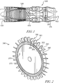
- FIG. 1 is a cross-sectional view of a turbine engine 100 according to one an embodiment of the present disclosure.
- the engine 100 includes an air intake portion 110, a compressor portion 120, a combustion portion 130, a turbine portion 135, and an exhaust portion 150.
- the engine 100 can be used in any suitable application, such as, for example, to produce thrust in aircraft applications, to drive a propeller in aquatic applications, or to drive a generator in energy applications.
- air received from the intake portion 110 is compressed within the compressor portion 120.
- the compressor portion 120 includes a series of bladed disks to form a multi-stage, axial compressor.
- the compressed air is then mixed with fuel and the mixture is burned in combustion portion 130.
- the combustion portion 130 can include any suitable fuel injection and combustion mechanisms.
- the hot, high pressure gas is then passed through the turbine portion 135 to extract energy from the gas which in turn drives the compressor portion 120 while discharging thrust out the exhaust portion 150.
- the turbine portion 135 includes a series of turbine blisks (or disk assemblies) 140.
- the blisks 140 form a multi-stage turbine.
- the gas temperatures within the turbine portion 135 can reach temperatures at or above 1093.3 °C (2000 °F), 1315.6 °C (2400 °F) or higher.
- certain components within the turbine portion 135, such as the flow path portion of the blisks 240 can reach temperatures of between 871.1 (1600) and 1037.8 °C (1900 °F), and higher, due to the heat transferred from the hot gas.
- the blisks 140 can include blades that are constructed from a ceramic matrix composite (CMC) material.
- CMC ceramic matrix composite
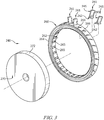
- FIG. 2 is an illustration of a blade and disk assembly, or blisk assembly 240, that can be used as a blisk 140 included within the engine 100 or any other suitable turbomachinery.
- the blisk assembly 240 includes a series of blades 241, a coupling member 260, and a disk 270.
- the disk 270 includes an outer surface 272 that is a continuous, circumferential surface as shown in FIGS. 3-5 .
- the blades 241 are spaced circumferentially around the disk 270 and extend radially outward from the disk 270.
- the coupling member 260 is illustratively a ring formed to include openings 266 that receive roots 242 of the blades 241 while allowing airfoils 245 of the blades 241 to extend through the coupling member 260 to trap the blades 241 in place around the disk 270 as suggested in FIGS. 2-5 .
- the outer surface 272 of the disk 270 is devoid of discontinuities, such as, for example, grooves, slots, apertures or other "cut-outs" (e.g., within which a portion of the blade 241 can be mounted) as shown in FIGS. 3 and 4 .
- the outer surface 272 is illustratively devoid of any posts, lugs or other protruding mounting surfaces configured to retain or secure the blades 241.
- the disk 270 is configured to reduce and/or eliminate "dead load" in the outer portion.
- the disk 270 is illustratively configured to reduce and/or eliminate portions thereof, such as lugs or connecting protrusions, that add weight to and/or increase the diameter of the assembly without providing a corresponding amount of strength.
- the coupling member 260 has a first (or inner) surface 262 and a second (or outer) surface 264, and defines a series of openings 266 that extend radially through the first surface 262 and the second surface 264 as shown in FIGS. 3-5 .
- a side wall 265 of the openings 266 formed in the coupling member 260 defines the openings 266.
- a portion of the blade 241 is disposed within the opening 266 to couple the blade 241 to the disk 270.
- the inner surface 262 of the coupling member 260 is configured to be coupled to the outer surface 272 of the disk 270 to couple the blades 241, the coupling member 260 and the disk 270 together to form the blisk 240.
- the inner surface 262 of the coupling member 260 can be coupled to the outer surface 272 of the disk 270 in any suitable manner.
- the coupling member 260 surrounds the outer surface 272 of the disk 270, such that the coupling member 260 is disposed about the disk 270.
- a diameter of the inner surface 262 and a diameter of the outer surface 272 of the disk 270 are sized to form an interference or "press" fit to couple (or assist in the coupling of) the coupling member 260 to the disk 270.
- the coupling member 260 can be brazed or bonded to the disk 270.
- the coupling member 260 and/or the disk 270 can be fabricated from any suitable material.
- the coupling member 260 and/or the disk 270 can be constructed from a cast and/or wrought alloy.
- the surfaces described herein e.g., the inner surface 262 of the coupling member 260 and/or the outer surface 272 of the disk 270
- the blade 241 includes a root 242 that has a coupling surface 244 and an end surface 246. As shown, a portion of the blade 241 is disposed within the opening 266 of the coupling member 260 when the coupling member 260 is coupled to the outer surface 272 of the disk 270 such that the blade 241 is coupled to the disk 270. More particularly, the root 242 of the blade is secured within the opening 266 such that the blade 241 is coupled to the disk 270 via the coupling member 260.
- the root 242 of the blade 241 includes a coupling surface 244 that corresponds to and/or matingly couples to a portion of the side wall 265 that defines the opening 266 as suggested in FIGS. 3 and 5 .
- the coupling surface 244 and the opening 266 form a dovetail attachment.
- the blade 241 can be coupled to the coupling member 260 (and therefore the disk 270) without the use of a fixed fastener, welding or brazing.
- the blade 241 is trapped between the disk 270 and the coupling member 260 such that relative movement of the blade 241 relative to the disk 270 is blocked. This arrangement can accommodate the coupling of dissimilar materials (e.g., a CMC blade and a metallic disk) which leads to differing rates of thermal expansion.
- relative motion between the blade 241 and the coupling member 260 and/or disk 270 is allowed.
- the end surface 246 of the blade root 242 may be spaced apart from the outer surface 272 of the disk 270 and/or the inner surface 262 of the coupling member 260 by a distance d when the coupling member 260 is coupled to the disk 270.
- This arrangement can accommodate variations in tolerance, differing rates of thermal expansion (i.e. between the blade 241 and the disk 270) and the like.
- this arrangement allows relative motion between the blade 241 and the coupling member 260 and/or disk 270 while maintaining the blades 241 securely coupled to the disk 270.
- the centrifugal load pulls the blades 241 away from the center of the disk 270.
- the dovetail shape coupling secures the blades 241 within the openings 266.
- the blade may experience a centrifugal force and/or load of up to 90,000 G.
- the distance d (or end clearance when cold and not operating) can be between about 0.0508 mm (0.002 inches) and about 0.127 mm (0.005 inches). In other embodiments, the distance d (or end clearance when cold and not operating) can be less than about 0.0508 mm (0.002 inches).
- the blades 241 are described as being coupled within the coupling member 260 via a tapered or dovetail joint, in other embodiments, the blades 241 can be coupled within the coupling member 260 using any attachment mechanism. Such attachment mechanisms can include a spherical fitting, a pin fitting, a flat T-type fitting, and/or the like. Moreover, although the blades 241 are described as being coupled within the coupling member 260 in a manner that allows some relative motion, in other embodiments, the blades 241 can be coupled within the coupling member 260 in a manner that eliminates and/or prevents any relative motion therebetween.
- the blades 241 can be constructed from any suitable material, such a ceramic matrix composite (CMC) material.
- CMC ceramic matrix composite
- the blade 241 can be constructed from a ceramic matrix reinforced by a refractory fiber, such as silicon carbide (SiC) fiber (e.g., a SiC-SiC CMC).
- SiC silicon carbide
- the blade 241 can be devoid of a platform or integral flow path portion.
- the coupling member 260 defines one or more flow paths to direct the flow of gas within the turbine portion and/or between the leading edge and trailing edge of the blades 241. Accordingly, in some embodiments, the coupling member can be referred to as a "flow path" ring.
- the coupling member or flow path ring 260 can be coupled to the disk 270 to form the blisk 240 in any suitable manner.
- the coupling member 260 can be coupled to the disk 270 by a bonding or braze joint.
- the disk 270 can support and/or carry at least a portion of the centrifugal load that is imparted onto the ring 260 by the blades 241 during use. More particularly, this arrangement can limit centrifugal (or "CF") loading during operation of the blisk 240. Because the blades 241 are inserted into openings 266 in the coupling member 260, which is, in some embodiments, bonded to the disk 270, no additional attachment is used to mount the blades 241.
- the distance between the last continuous fiber of the outer surface 272 of the disk 270 and/or the outer surface 264 of the coupling member 260 and the tips of the blades 241 can be minimized.
- the blades 241 can be CMC blades, which further reduce the mass of the blisk 240. Because the CF force is a function of the mass, a reduction in mass will decrease the CF load.
- the blades 241 are inserted into the openings 266 of the coupling member 260 such that the root 242 of the blade 241 is matingly disposed against the coupling portion 244.
- the blades 421 and coupling member 260 can then be heated to about 148.9 °C (300 °F).
- the disk 105 can be cooled or frozen, and in certain implementations it may be cooled to a temperature of between about -62.2 °C (-80 °F) and about -73.3 °C (-100 °F). In this manner, the outer diameter of the disk 270 can decrease while the inner diameter of the coupling member 260 can increase, thus allowing for assembly.
- the disk 270 may be cooled using any suitable mechanism, such as liquid nitrogen, carbon dioxide, and/or the like.
- a braze material such as a Boron braze (diffusion braze) or a standard "wide gap” braze material, is applied to the inner surface 262 of the coupling member 260 and/or the outer surface 272 of the disk 270.
- the heated coupling member 260 is then disposed about the cooled disk 270.
- the coupling member 260 and disk 270 are securely fastened together to form the one piece blisk.
- the coupling member 260 and disk 270 can be heated to a temperature of between about 1093.3 °C (2000 °F) and about 1204.4 °C (2200 °F) for between about one and about five hours.
- the braze material can be applied in any suitable manner, such as, for example, by first applying a powder (which can be formulated to refrain from melting at the braze temperature), followed by a filler metal.
- the powder can be applied by spraying, by slurry introduction methods or the like.
- the coupling member 260 and the disk 270 can then be heated to allow the filler metal to be drawn into the gaps containing the powder, thus producing a substantially uniform material within the gaps between the two parts.
- a diffusion bond may attach the coupling member 260 to the disk 270.
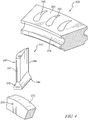
- FIGS. 2-4 are perspective views of blade 241 and a coupling member 260 (or "flow path ring") according to an embodiment.
- the blade 241 includes a root 242 that has a coupling surface 244.
- the blade 241 also includes an airfoil 245 with a leading edge 247 and a trailing edge 248, and is devoid of any integral flow path segment (sometimes called a platform).
- the blade 241 illustratively comprises ceramic matrix composite materials but can be of metallic or other construction.
- the coupling member 260 has an inner surface 262 and an outer surface 264, and defines a series of openings 266 as shown in Figs. 2-5 . As shown, the openings 266 are shaped to conform to the leading edge 247 and trailing edge 248 of the airfoil 245 included in the blade 341.
- the coupling member 260 also includes a connection portion 274, which can facilitate the attachment and/or bonding of the coupling member 260 to the disk 270, as described in more detail herein.
- the root 242 of the blade 241 is disposed within the corresponding opening 266 to couple the blade 241 to the disk 270.
- the inner surface of the coupling member 260 is configured to be coupled to the disk to couple the blades 241, the coupling member 260 and the disk together to form a blisk, as described herein.
- a coupling member can be constructed from multiple pieces that are later joined (e.g., during the brazing, attachment and/or bonding process) to form a continuous structure that couples the blades to the disk, as described herein.
- a blisk can be constructed of multiple coupling members and/or flow path segments. Such construction can allow for the assembly of blades having an integral tip shroud.
- a coupling member 240 can include multiple pieces that are separated along an axis substantially normal to the circumferential axis as suggested by the phantom line in Fig. 4 . Such an arrangement can allow the blades to be disposed within the opening without passing the blade tip through the opening.
- the coupling members are described herein as being bonded to the underlying disk via a braze joint, in other embodiments, a coupling member (either a monolithically constructed coupling member or a coupling member constructed from multiple components) can be coupled to a disk in any suitable manner.
- FIG. 6 is a flow chart of a method 400 of assembling a blisk according to an embodiment.
- the method 400 includes inserting a blade through an opening defined by a coupling member such that a root of the blade is matingly disposed within the opening, at 401.
- the blade can be any of the blades described herein, such as blade 241 and the coupling member can be any suitable coupling member, such as the coupling member 260.
- the blade and the coupling member are then heated, at 410.
- the blade and the coupling member can be heated to any suitable temperature, such as, for example to about 148.9 °C (300 °F).
- the coupling member (and blade) are then disposed about a disk, at 420.
- the disk can be any suitable disk, such as the disk 270 described herein.
- the disk can be cooled before the coupling member is disposed about the disk, as described above.
- the method optionally includes applying a braze material to the outer surface of the disk and/or the inner surface of the coupling member, at 430.
- the assembly of the coupling member, blade and disk can be heated after the coupling member is disposed about the disk, 440. In this manner, a braze joint can be formed between the outer surface of the disk and the inner surface of the coupling member.
- the coupling member (and the disk) is then cooled such that an inner surface of the coupling member is in contact with an outer surface of the disk, at 450.
- FIGS. 7 and 8 Another non claimed blisk 440 is shown in FIGS. 7 and 8 .
- the blisk 440 is configured for use in engine 100 and is substantially similar to the blisk 240 shown in Figs. 2-6 and described herein. Accordingly, similar reference numbers in the 400 series indicate features that are common between the blisk 240 and the blisk 440.
- the description of the engine 100 and the blisk 240 is hereby incorporated by reference to apply to the blisk 440, except in instances when it conflicts with the specific description and drawings of the blisk 440.
- the coupling member 460 included in the blisk 440 is formed to include relief slots 461 as shown in FIGS. 7 and 8 .
- the relief slots 461 are illustratively arranged circumferentially between openings 466 through which blades 441 extend and are arranged to extend from an axially forward side to an axially aft side of the coupling member 460.
- each relief slot 461 extends partway radially from an outer surface of the coupling member 460 toward the disk 470.
- the relief slots 461 may extend in the radial direction all the way through the coupling member 460 as suggested in phantom in FIG. 8 .
- the relief slots 461 are formed by wire cuts in an optional step that may be added to the method 400.
- Turbine blisks (or turbine disk assemblies) including CMC blades are described herein.
- the assemblies described herein may be used in a turbine engine (e.g., a jet engine).
- an apparatus includes a disk, a coupling member, and a set of blades.
- the disk has an outer surface that is a continuous, circumferential surface.
- the coupling member illustratively forms a ring around the disk and defines a set of openings formed to extend radially outward from the disk.
- a portion of a blade from the set of blades is disposed within one of the openings and is sized so that a root of the blade is trapped between the disk and the coupling member to couple the blade to the disk while an airfoil of the blade extends radially outward from the coupling member.
- an apparatus in some embodiments, includes a disk having an outer surface, a coupling member, and a set of blades.
- the coupling member defines a set of openings, and is configured to be bonded to the outer surface of the disk.
- the outer surface need not be continuous, and can have, for example, protrusions or other localized features to facilitate the bonding or joining of the coupling member to the disk.
- the coupling member is bonded to the outer surface of the disk via a braze joint. A portion of a blade from the set of blades is disposed within an opening from the set of openings when the coupling member is bonded to the outer surface of the disk such that the blade is coupled to the disk.
- a method of assembling a blisk includes inserting a blade through an opening defined by a coupling member such that a root of the blade is matingly disposed within the opening. The coupling member and the blade are heated. The coupling member is then disposed about a disk. The method further includes cooling the coupling member such that an inner surface of the coupling member is in contact with an outer surface of the disk. In some embodiments, the method optionally includes applying a braze material to the outer surface of the disk and/or the inner surface of the coupling member and heating the coupling member, blade, and disk to produce a braze joint between the outer surface of the disk and the inner surface of the coupling member.
- the outer diameter of the disk can be fabricated (e.g., machined) to form an interference fit with the inner diameter of the coupling member, such that the coupling member fixedly encircles or surrounds the disk.
- the coupling member and/or the disk can be fabricated from a cast and/or wrought alloy.
- the coupling member defines one or more flow paths, and may be referred to as a "flow path ring.”
- blisks have been described herein as being turbine blisks, in other embodiments any of the structures and methods described herein can be used in conjunction with a compressor wheel or disk assembly.
- the terms "about” and “approximately” generally mean plus or minus 10% of the value stated. For example, about 0.5 would include 0.45 and 0.55, about 10 would include 9 to 11, about 1000 would include 900 to 1100.
- Such variances can result from manufacturing tolerances, measurement tolerances, tolerance stacking, and/or other practical considerations (such as, for example, a force exerted on and/or otherwise experienced by a structure). For example, a variance may result from a manufacturing tolerance associated with a given manufacturing process.
- manufacturing tolerances may be plus or minus less than 1%, 2%, 3%, 4%, 5%, 6%, 7%, 8%, 9%, 10%, or more of the stated value.
- the first aspect of the present invention comprises a turbine disk assembly adapted for use in a gas turbine engine, the assembly comprising a disk comprising metallic materials and forming an outer surface, the outer surface being a continuous circumferential surface that extends around a central axis that defines an axial direction parallel thereto and a radial direction perpendicular thereto, a blade comprising ceramic matrix composite materials, the blade including a root arranged radially outward of the outer surface formed by the disk and an airfoil extending radially outward from the root, a ring coupled to the disk and extending around the outer surface formed by the disk, the ring formed to include an opening, wherein the opening formed in the ring extends radially through the ring from a radially-inner surface (262) of the ring to a radially-outer surface (264) of the ring, said opening receives at least a portion of the root included in the blade to couple the blade to the ring while at least a portion of the airfoil included in
- root of the blade forms one of a dovetail shape, a tapered shape, and a generally cylindrical shape; and the opening formed in the ring forms a negative shape corresponding to at least a portion of the root.
- a turbine disk assembly adapted for use in a gas turbine engine, the assembly comprising a disk having an outer surface, the outer surface being a continuous circumferential surface; a coupling member having a first surface and a second surface, and defining a plurality of openings between the first surface and the second surface, the first surface configured to be coupled to the outer surface of the disk; and a plurality of blades, a portion of a blade from the plurality of blades being disposed within an opening from the plurality of openings when the first surface of the coupling member is coupled to the outer surface of the disk such that the blade is coupled to the disk.
- the portion of the blade is a root of the blade, the root having an end surface that is spaced radially apart from the outer surface of the disk when the first surface of the coupling member is coupled to the outer surface of the disk.
- the blade from the plurality of blades is constructed from a ceramic matrix composite material.
- the assembly of a non claimed arrangement further comprising a damper between the coupling member and the plurality of blades, wherein the damper is configured to dampen vibration.
- a second aspect of the present invention concerns a method of constructing a turbine disk assembly adapted for use in a gas turbine engine, the method comprising inserting a blade through an opening defined by a coupling member such that a root of the blade is matingly disposed within the opening; heating the coupling member, cooling a disk, disposing the coupling member about the disk, and equalizing the temperature of the disk and the coupling member such that an inner surface of the coupling member is in contact with an outer surface of the disk turbine.
- any suitable embodiment further comprising applying a braze material to at least one of the outer surface of the disk and the inner surface of the coupling member; and heating the coupling member, blade, and disk to produce a braze joint between the outer surface of the disk and the inner surface of the coupling member.
- the ring forms a one-piece full hoop extending around the central axis and the opening is spaced apart from an axially-forward side and an axially-aft side of the coupling member.
Claims (11)
- Turbinenscheibenanordnung, die zur Verwendung in einem Gasturbinentriebwerk angeordnet ist, wobei die Anordnung
eine Scheibe (270) umfasst, die metallische Materialien umfasst und eine Außenfläche (272) bildet, wobei die Außenfläche eine kontinuierliche Umfangsfläche ist, die sich um eine Mittelachse erstreckt, die eine dazu parallele Axialrichtung und eine dazu senkrechte Radialrichtung definiert,
eine Schaufel (241), die keramische Matrix-Verbundwerkstoffe umfasst, wobei die Schaufel eine Wurzel (242) umfasst, die radial nach außen von der durch die Scheibe gebildeten Außenfläche angeordnet ist, und ein Profil, das sich radial nach außen von der Wurzel erstreckt,
einen Ring, der mit der Scheibe gekoppelt ist und sich um die durch die Scheibe gebildete Außenfläche erstreckt, wobei der Ring gebildet ist, um eine Öffnung (266) zu enthalten, wobei sich die in dem Ring gebildete Öffnung radial durch den Ring von einer radial inneren Oberfläche (262) des Rings zu einer radial äußeren Oberfläche (264) des Rings erstreckt, wobei die Öffnung mindestens einen Abschnitt der in der Schaufel enthaltenen Wurzel aufnimmt, um die Schaufel mit dem Ring zu verbinden, während mindestens ein Teil des in der Schaufel enthaltenen Profils außerhalb der Öffnung radial außerhalb des Rings angeordnet ist, um mit Gasen radial außerhalb des Rings zu interagieren, und
wobei der Durchmesser der von der Scheibe gebildeten äußeren Oberfläche größer ist als eine radial innere Oberfläche des Rings, wenn die Scheibe und der Ring auf derselben Temperatur sind, sodass die Scheibe und der Ring in Presspassung miteinander sind. - Anordnung nach Anspruch 1, wobei der Ring über eine Lötverbindung, die zwischen der radial inneren Oberfläche des Rings und der durch die Scheibe gebildeten Außenfläche angeordnet ist, mit der Scheibe verbunden ist.
- Anordnung nach Anspruch 2, wobei die Wurzel der Schaufel nicht mit der Scheibe verbunden ist.
- Anordnung nach Anspruch 1, wobei der Ring über eine Lötverbindung, die zwischen der radial inneren Oberfläche des Rings und der von der Scheibe gebildeten Außenfläche angeordnet ist, mit der Scheibe verbunden ist; und die Wurzel der Schaufel nicht mit der Scheibe verbunden ist.
- Anordnung nach einem der vorherigen Ansprüche, wobei die Wurzel der Schaufel eine von einer Schwalbenschwanzform, einer konischen Form und einer generell zylindrischen Form bildet; und die in dem Ring gebildete Öffnung eine negative Form bildet, die mindestens einem Abschnitt der Wurzel entspricht.
- Anordnung nach einem der vorherigen Ansprüche, wobei der Ring ein einteiliges volles Band bildet, das sich um die Mittelachse erstreckt.
- Anordnung nach einem der vorherigen Ansprüche, wobei die Öffnung von einer axial vorderen Seite und einer axial hinteren Seite des Rings beabstandet ist.
- Anordnung nach einem der vorherigen Ansprüche, wobei die radial äußere Oberfläche des Rings eine Oberfläche bereitstellt, die eine Strömungsbahn definiert.
- Verfahren zur Herstellung einer Turbinenscheibenanordnung, die für die Verwendung in einem Gasturbinentriebwerk geeignet ist, wobei das Verfahren Folgendes umfasst
Einsetzen einer Schaufel (241), die keramische Matrix-Verbundwerkstoffe umfasst, durch eine Öffnung, die durch einen Ring (260) definiert ist,
sodass eine Wurzel der Schaufel in der Öffnung passend angeordnet ist;
Erhitzen des Rings (260),
Abkühlen einer Scheibe (270), die metallische Materialien umfasst,
Anordnen des Rings (260) um die Scheibe, und
Ausgleichen der Temperatur der Scheibe und des Rings (260), sodass eine Innenfläche des Rings (260) mit einer Außenfläche der Scheibe (270) in Kontakt ist. - Verfahren nach Anspruch 9, ferner umfassend
Anwenden eines Lötmaterials auf mindestens eine der Außenfläche der Scheibe und der Innenfläche des Kopplungselements; und
Erhitzen des Kopplungselements, der Schaufel und der Scheibe, um eine Lötverbindung zwischen der Außenfläche der Scheibe und der Innenfläche des Kopplungselements herzustellen. - Verfahren nach Anspruch 9 oder 10, wobei der Ring einen einteiliges volles Band bildet, das sich um die Mittelachse erstreckt, und die Öffnung von einer axial vorderen Seite und einer axial hinteren Seite des Kopplungselements beabstandet ist.
Applications Claiming Priority (1)
| Application Number | Priority Date | Filing Date | Title |
|---|---|---|---|
| US201462078761P | 2014-11-12 | 2014-11-12 |
Publications (2)
| Publication Number | Publication Date |
|---|---|
| EP3023581A1 EP3023581A1 (de) | 2016-05-25 |
| EP3023581B1 true EP3023581B1 (de) | 2019-01-09 |
Family
ID=54539956
Family Applications (1)
| Application Number | Title | Priority Date | Filing Date |
|---|---|---|---|
| EP15194059.0A Not-in-force EP3023581B1 (de) | 2014-11-12 | 2015-11-11 | Turbinendiskanordnung mit keramikmatrix-verbundstoffschaufeln und verfahren zur herstellung |
Country Status (2)
| Country | Link |
|---|---|
| US (1) | US10280768B2 (de) |
| EP (1) | EP3023581B1 (de) |
Families Citing this family (18)
| Publication number | Priority date | Publication date | Assignee | Title |
|---|---|---|---|---|
| US10914320B2 (en) * | 2014-01-24 | 2021-02-09 | Raytheon Technologies Corporation | Additive manufacturing process grown integrated torsional damper mechanism in gas turbine engine blade |
| US10125619B2 (en) * | 2015-11-19 | 2018-11-13 | General Electric Company | Rotor assembly for use in a turbofan engine and method of assembling |
| US10294954B2 (en) | 2016-11-09 | 2019-05-21 | Rolls-Royce North American Technologies Inc. | Composite blisk |
| US10711616B2 (en) * | 2016-11-17 | 2020-07-14 | Raytheon Technologies Corporation | Airfoil having endwall panels |
| US10934865B2 (en) | 2017-01-13 | 2021-03-02 | Rolls-Royce Corporation | Cooled single walled blisk for gas turbine engine |
| US10247015B2 (en) | 2017-01-13 | 2019-04-02 | Rolls-Royce Corporation | Cooled blisk with dual wall blades for gas turbine engine |
| US10415403B2 (en) | 2017-01-13 | 2019-09-17 | Rolls-Royce North American Technologies Inc. | Cooled blisk for gas turbine engine |
| US10563665B2 (en) | 2017-01-30 | 2020-02-18 | Rolls-Royce North American Technologies, Inc. | Turbomachine stage and method of making same |
| US10718218B2 (en) | 2018-03-05 | 2020-07-21 | Rolls-Royce North American Technologies Inc. | Turbine blisk with airfoil and rim cooling |
| CN108363890B (zh) * | 2018-03-21 | 2021-09-28 | 西北工业大学 | 开式整体叶盘通道插铣粗加工的材料残余高度评估方法 |
| US11268389B2 (en) * | 2018-05-14 | 2022-03-08 | Rolls-Royce North American Technologies Inc. | Blisk bonded CMC airfoil having attachment |
| US10787916B2 (en) | 2018-06-22 | 2020-09-29 | Rolls-Royce Corporation | Turbine wheel assembly with ceramic matrix composite components |
| US10801338B1 (en) | 2018-07-18 | 2020-10-13 | Florida Turbine Technologies, Inc. | Apparatus and process of forming an integrally bladed rotor with cooled single crystal blades and an equiax nickel disk |
| US10641111B2 (en) * | 2018-08-31 | 2020-05-05 | Rolls-Royce Corporation | Turbine blade assembly with ceramic matrix composite components |
| US10934863B2 (en) | 2018-11-13 | 2021-03-02 | Rolls-Royce Corporation | Turbine wheel assembly with circumferential blade attachment |
| US11187104B2 (en) | 2019-10-28 | 2021-11-30 | Pratt & Whitney Canada Corp. | In-situ heating/cooling tool for turbine assembly on a shaft |
| CN111365079A (zh) * | 2020-04-01 | 2020-07-03 | 南京航空航天大学 | 陶瓷基复合材料涡轮转子叶片盘榫连接结构及涡轮盘 |
| US11834960B2 (en) * | 2022-02-18 | 2023-12-05 | General Electric Company | Methods and apparatus to reduce deflection of an airfoil |
Family Cites Families (29)
| Publication number | Priority date | Publication date | Assignee | Title |
|---|---|---|---|---|
| GB750397A (en) * | 1951-12-10 | 1956-06-13 | Power Jets Res & Dev Ltd | Damped turbine and dynamic compressor blades |
| US2944326A (en) * | 1955-06-02 | 1960-07-12 | Gen Electric | Method of staking blades |
| US3146635A (en) * | 1961-05-22 | 1964-09-01 | United Aircraft Corp | Rotor balancing sleeve |
| GB1276100A (en) * | 1968-12-16 | 1972-06-01 | Rolls Royce | Bladed member for a fluid flow machine |
| US4152816A (en) * | 1977-06-06 | 1979-05-08 | General Motors Corporation | Method of manufacturing a hybrid turbine rotor |
| DE2915201C2 (de) | 1979-04-14 | 1986-02-27 | MTU Motoren- und Turbinen-Union München GmbH, 8000 München | Laufrad für Axialströmungsmaschinen, insbesondere Verdichter |
| US4270256A (en) | 1979-06-06 | 1981-06-02 | General Motors Corporation | Manufacture of composite turbine rotors |
| US4305697A (en) * | 1980-03-19 | 1981-12-15 | General Electric Company | Method and replacement member for repairing a gas turbine engine vane assembly |
| US4494287A (en) | 1983-02-14 | 1985-01-22 | Williams International Corporation | Method of manufacturing a turbine rotor |
| US5022822A (en) | 1989-10-24 | 1991-06-11 | United Technologies Corporation | Compressor blade attachment assembly |
| FR2679599A1 (fr) | 1991-07-24 | 1993-01-29 | Snecma | Perfectionnement aux roues a aubes de turbomachines. |
| FR2697284B1 (fr) | 1992-10-27 | 1995-01-27 | Europ Propulsion | Procédé de fabrication d'une roue de turbine à aubes insérées et roue obtenue par le procédé. |
| US5425622A (en) | 1993-12-23 | 1995-06-20 | United Technologies Corporation | Turbine blade attachment means |
| US5609471A (en) | 1995-12-07 | 1997-03-11 | Allison Advanced Development Company, Inc. | Multiproperty rotor disk and method of manufacture |
| US6224339B1 (en) * | 1998-07-08 | 2001-05-01 | Allison Advanced Development Company | High temperature airfoil |
| DE10358421A1 (de) | 2003-12-13 | 2005-07-07 | Mtu Aero Engines Gmbh | Rotor für eine Turbomaschine |
| US7784182B2 (en) | 2006-11-08 | 2010-08-31 | General Electric Company | System for manufacturing a rotor having an MMC ring component and a unitary airfoil component |
| US7832986B2 (en) | 2007-03-07 | 2010-11-16 | Honeywell International Inc. | Multi-alloy turbine rotors and methods of manufacturing the rotors |
| US8206117B2 (en) | 2007-12-19 | 2012-06-26 | Honeywell International Inc. | Turbine components and methods of manufacturing turbine components |
| EP2075417B1 (de) | 2007-12-27 | 2016-04-06 | Techspace Aero | Plattform für ein beschaufeltes Laufrad einer Strömungsmaschine, beschaufeltes Laufrad und Kompressor oder Strömungsmaschine, die ein solches Laufrad umfassen |
| US8408874B2 (en) | 2008-04-11 | 2013-04-02 | United Technologies Corporation | Platformless turbine blade |
| US8814524B2 (en) | 2008-12-11 | 2014-08-26 | Rolls-Royce Corporation | Wheel formed from a bladed ring and disk |
| FR2940353B1 (fr) | 2008-12-23 | 2011-02-11 | Snecma | Roue mobile de turbomachine a aubes en materiau composite. |
| DE102009052783A1 (de) | 2009-11-11 | 2011-05-12 | Mtu Aero Engines Gmbh | Verfahren zum Herstellen einer Blisk oder eines Blings für eine Strömungsmaschine |
| GB201005270D0 (en) | 2010-03-30 | 2010-05-12 | Rolls Royce Plc | A method and apparatus for manufacturing a rotor disc |
| FR2961847B1 (fr) | 2010-06-25 | 2012-08-17 | Snecma | Roue mobile a aubes en materiau composite pour moteur a turbine a gaz a liaison pied d'aube/disque par serrage |
| GB201010929D0 (en) | 2010-06-30 | 2010-08-11 | Rolls Royce Plc | A turbine rotor assembly |
| US8939727B2 (en) | 2011-09-08 | 2015-01-27 | Siemens Energy, Inc. | Turbine blade and non-integral platform with pin attachment |
| US9175571B2 (en) | 2012-03-19 | 2015-11-03 | General Electric Company | Connecting system for metal components and CMC components, a turbine blade retaining system and a rotating component retaining system |
-
2015
- 2015-11-10 US US14/937,260 patent/US10280768B2/en active Active
- 2015-11-11 EP EP15194059.0A patent/EP3023581B1/de not_active Not-in-force
Non-Patent Citations (1)
| Title |
|---|
| None * |
Also Published As
| Publication number | Publication date |
|---|---|
| US20160130957A1 (en) | 2016-05-12 |
| US10280768B2 (en) | 2019-05-07 |
| EP3023581A1 (de) | 2016-05-25 |
Similar Documents
| Publication | Publication Date | Title |
|---|---|---|
| EP3023581B1 (de) | Turbinendiskanordnung mit keramikmatrix-verbundstoffschaufeln und verfahren zur herstellung | |
| US10683770B2 (en) | Turbine shroud assembly having ceramic matrix composite track segments with metallic attachment features | |
| EP3037628B1 (de) | Turbinenummantelung | |
| EP3091187B1 (de) | Turbinenkomponentenanordnung mit thermisch spannungsfreier befestigung | |
| EP3020926B1 (de) | Turbinenscheibenanordnung mit trennbaren plattformen zur schaufelbefestigung | |
| EP2653652B1 (de) | Axial aufgeteilte Radialturbine | |
| JP6255051B2 (ja) | ガスタービンエンジンの隣接ノズルを配置するための方法 | |
| US20140212284A1 (en) | Hybrid turbine nozzle | |
| US10577951B2 (en) | Gas turbine engine with dovetail connection having contoured root | |
| EP2978937B1 (de) | Nicht integrierte schaufel und plattformsegment für einen rotor und zugehöriges verfahren | |
| US10767496B2 (en) | Turbine blade assembly with mounted platform | |
| US10890081B2 (en) | Turbine disk with platforms coupled to disk | |
| EP3287601B1 (de) | Mehrteilige nichtlineare bläserschaufel | |
| US20200018177A1 (en) | Turbine wheel assembly with ceramic matrix composite blades | |
| US10787916B2 (en) | Turbine wheel assembly with ceramic matrix composite components | |
| US20190376392A1 (en) | Gas turbine |
Legal Events
| Date | Code | Title | Description |
|---|---|---|---|
| AK | Designated contracting states |
Kind code of ref document: A1 Designated state(s): AL AT BE BG CH CY CZ DE DK EE ES FI FR GB GR HR HU IE IS IT LI LT LU LV MC MK MT NL NO PL PT RO RS SE SI SK SM TR |
|
| AX | Request for extension of the european patent |
Extension state: BA ME |
|
| PUAI | Public reference made under article 153(3) epc to a published international application that has entered the european phase |
Free format text: ORIGINAL CODE: 0009012 |
|
| 17P | Request for examination filed |
Effective date: 20161021 |
|
| RBV | Designated contracting states (corrected) |
Designated state(s): AL AT BE BG CH CY CZ DE DK EE ES FI FR GB GR HR HU IE IS IT LI LT LU LV MC MK MT NL NO PL PT RO RS SE SI SK SM TR |
|
| GRAP | Despatch of communication of intention to grant a patent |
Free format text: ORIGINAL CODE: EPIDOSNIGR1 |
|
| STAA | Information on the status of an ep patent application or granted ep patent |
Free format text: STATUS: GRANT OF PATENT IS INTENDED |
|
| INTG | Intention to grant announced |
Effective date: 20180605 |
|
| GRAS | Grant fee paid |
Free format text: ORIGINAL CODE: EPIDOSNIGR3 |
|
| GRAA | (expected) grant |
Free format text: ORIGINAL CODE: 0009210 |
|
| STAA | Information on the status of an ep patent application or granted ep patent |
Free format text: STATUS: THE PATENT HAS BEEN GRANTED |
|
| AK | Designated contracting states |
Kind code of ref document: B1 Designated state(s): AL AT BE BG CH CY CZ DE DK EE ES FI FR GB GR HR HU IE IS IT LI LT LU LV MC MK MT NL NO PL PT RO RS SE SI SK SM TR |
|
| REG | Reference to a national code |
Ref country code: GB Ref legal event code: FG4D |
|
| REG | Reference to a national code |
Ref country code: CH Ref legal event code: EP Ref country code: AT Ref legal event code: REF Ref document number: 1087541 Country of ref document: AT Kind code of ref document: T Effective date: 20190115 |
|
| REG | Reference to a national code |
Ref country code: IE Ref legal event code: FG4D |
|
| REG | Reference to a national code |
Ref country code: DE Ref legal event code: R096 Ref document number: 602015023114 Country of ref document: DE |
|
| RAP2 | Party data changed (patent owner data changed or rights of a patent transferred) |
Owner name: ROLLS-ROYCE CORPORATION |
|
| REG | Reference to a national code |
Ref country code: NL Ref legal event code: MP Effective date: 20190109 |
|
| REG | Reference to a national code |
Ref country code: LT Ref legal event code: MG4D |
|
| PG25 | Lapsed in a contracting state [announced via postgrant information from national office to epo] |
Ref country code: NL Free format text: LAPSE BECAUSE OF FAILURE TO SUBMIT A TRANSLATION OF THE DESCRIPTION OR TO PAY THE FEE WITHIN THE PRESCRIBED TIME-LIMIT Effective date: 20190109 |
|
| REG | Reference to a national code |
Ref country code: AT Ref legal event code: MK05 Ref document number: 1087541 Country of ref document: AT Kind code of ref document: T Effective date: 20190109 |
|
| PG25 | Lapsed in a contracting state [announced via postgrant information from national office to epo] |
Ref country code: NO Free format text: LAPSE BECAUSE OF FAILURE TO SUBMIT A TRANSLATION OF THE DESCRIPTION OR TO PAY THE FEE WITHIN THE PRESCRIBED TIME-LIMIT Effective date: 20190409 Ref country code: FI Free format text: LAPSE BECAUSE OF FAILURE TO SUBMIT A TRANSLATION OF THE DESCRIPTION OR TO PAY THE FEE WITHIN THE PRESCRIBED TIME-LIMIT Effective date: 20190109 Ref country code: LT Free format text: LAPSE BECAUSE OF FAILURE TO SUBMIT A TRANSLATION OF THE DESCRIPTION OR TO PAY THE FEE WITHIN THE PRESCRIBED TIME-LIMIT Effective date: 20190109 Ref country code: ES Free format text: LAPSE BECAUSE OF FAILURE TO SUBMIT A TRANSLATION OF THE DESCRIPTION OR TO PAY THE FEE WITHIN THE PRESCRIBED TIME-LIMIT Effective date: 20190109 Ref country code: PL Free format text: LAPSE BECAUSE OF FAILURE TO SUBMIT A TRANSLATION OF THE DESCRIPTION OR TO PAY THE FEE WITHIN THE PRESCRIBED TIME-LIMIT Effective date: 20190109 Ref country code: SE Free format text: LAPSE BECAUSE OF FAILURE TO SUBMIT A TRANSLATION OF THE DESCRIPTION OR TO PAY THE FEE WITHIN THE PRESCRIBED TIME-LIMIT Effective date: 20190109 Ref country code: PT Free format text: LAPSE BECAUSE OF FAILURE TO SUBMIT A TRANSLATION OF THE DESCRIPTION OR TO PAY THE FEE WITHIN THE PRESCRIBED TIME-LIMIT Effective date: 20190509 |
|
| PG25 | Lapsed in a contracting state [announced via postgrant information from national office to epo] |
Ref country code: LV Free format text: LAPSE BECAUSE OF FAILURE TO SUBMIT A TRANSLATION OF THE DESCRIPTION OR TO PAY THE FEE WITHIN THE PRESCRIBED TIME-LIMIT Effective date: 20190109 Ref country code: HR Free format text: LAPSE BECAUSE OF FAILURE TO SUBMIT A TRANSLATION OF THE DESCRIPTION OR TO PAY THE FEE WITHIN THE PRESCRIBED TIME-LIMIT Effective date: 20190109 Ref country code: GR Free format text: LAPSE BECAUSE OF FAILURE TO SUBMIT A TRANSLATION OF THE DESCRIPTION OR TO PAY THE FEE WITHIN THE PRESCRIBED TIME-LIMIT Effective date: 20190410 Ref country code: RS Free format text: LAPSE BECAUSE OF FAILURE TO SUBMIT A TRANSLATION OF THE DESCRIPTION OR TO PAY THE FEE WITHIN THE PRESCRIBED TIME-LIMIT Effective date: 20190109 Ref country code: IS Free format text: LAPSE BECAUSE OF FAILURE TO SUBMIT A TRANSLATION OF THE DESCRIPTION OR TO PAY THE FEE WITHIN THE PRESCRIBED TIME-LIMIT Effective date: 20190509 Ref country code: BG Free format text: LAPSE BECAUSE OF FAILURE TO SUBMIT A TRANSLATION OF THE DESCRIPTION OR TO PAY THE FEE WITHIN THE PRESCRIBED TIME-LIMIT Effective date: 20190409 |
|
| REG | Reference to a national code |
Ref country code: DE Ref legal event code: R097 Ref document number: 602015023114 Country of ref document: DE |
|
| PG25 | Lapsed in a contracting state [announced via postgrant information from national office to epo] |
Ref country code: DK Free format text: LAPSE BECAUSE OF FAILURE TO SUBMIT A TRANSLATION OF THE DESCRIPTION OR TO PAY THE FEE WITHIN THE PRESCRIBED TIME-LIMIT Effective date: 20190109 Ref country code: AT Free format text: LAPSE BECAUSE OF FAILURE TO SUBMIT A TRANSLATION OF THE DESCRIPTION OR TO PAY THE FEE WITHIN THE PRESCRIBED TIME-LIMIT Effective date: 20190109 Ref country code: CZ Free format text: LAPSE BECAUSE OF FAILURE TO SUBMIT A TRANSLATION OF THE DESCRIPTION OR TO PAY THE FEE WITHIN THE PRESCRIBED TIME-LIMIT Effective date: 20190109 Ref country code: SK Free format text: LAPSE BECAUSE OF FAILURE TO SUBMIT A TRANSLATION OF THE DESCRIPTION OR TO PAY THE FEE WITHIN THE PRESCRIBED TIME-LIMIT Effective date: 20190109 Ref country code: RO Free format text: LAPSE BECAUSE OF FAILURE TO SUBMIT A TRANSLATION OF THE DESCRIPTION OR TO PAY THE FEE WITHIN THE PRESCRIBED TIME-LIMIT Effective date: 20190109 Ref country code: AL Free format text: LAPSE BECAUSE OF FAILURE TO SUBMIT A TRANSLATION OF THE DESCRIPTION OR TO PAY THE FEE WITHIN THE PRESCRIBED TIME-LIMIT Effective date: 20190109 Ref country code: EE Free format text: LAPSE BECAUSE OF FAILURE TO SUBMIT A TRANSLATION OF THE DESCRIPTION OR TO PAY THE FEE WITHIN THE PRESCRIBED TIME-LIMIT Effective date: 20190109 Ref country code: IT Free format text: LAPSE BECAUSE OF FAILURE TO SUBMIT A TRANSLATION OF THE DESCRIPTION OR TO PAY THE FEE WITHIN THE PRESCRIBED TIME-LIMIT Effective date: 20190109 |
|
| PLBE | No opposition filed within time limit |
Free format text: ORIGINAL CODE: 0009261 |
|
| STAA | Information on the status of an ep patent application or granted ep patent |
Free format text: STATUS: NO OPPOSITION FILED WITHIN TIME LIMIT |
|
| PG25 | Lapsed in a contracting state [announced via postgrant information from national office to epo] |
Ref country code: SM Free format text: LAPSE BECAUSE OF FAILURE TO SUBMIT A TRANSLATION OF THE DESCRIPTION OR TO PAY THE FEE WITHIN THE PRESCRIBED TIME-LIMIT Effective date: 20190109 |
|
| 26N | No opposition filed |
Effective date: 20191010 |
|
| PGFP | Annual fee paid to national office [announced via postgrant information from national office to epo] |
Ref country code: DE Payment date: 20191127 Year of fee payment: 5 |
|
| PG25 | Lapsed in a contracting state [announced via postgrant information from national office to epo] |
Ref country code: SI Free format text: LAPSE BECAUSE OF FAILURE TO SUBMIT A TRANSLATION OF THE DESCRIPTION OR TO PAY THE FEE WITHIN THE PRESCRIBED TIME-LIMIT Effective date: 20190109 |
|
| PGFP | Annual fee paid to national office [announced via postgrant information from national office to epo] |
Ref country code: FR Payment date: 20191125 Year of fee payment: 5 |
|
| PG25 | Lapsed in a contracting state [announced via postgrant information from national office to epo] |
Ref country code: TR Free format text: LAPSE BECAUSE OF FAILURE TO SUBMIT A TRANSLATION OF THE DESCRIPTION OR TO PAY THE FEE WITHIN THE PRESCRIBED TIME-LIMIT Effective date: 20190109 |
|
| REG | Reference to a national code |
Ref country code: CH Ref legal event code: PL |
|
| PG25 | Lapsed in a contracting state [announced via postgrant information from national office to epo] |
Ref country code: MC Free format text: LAPSE BECAUSE OF FAILURE TO SUBMIT A TRANSLATION OF THE DESCRIPTION OR TO PAY THE FEE WITHIN THE PRESCRIBED TIME-LIMIT Effective date: 20190109 Ref country code: LI Free format text: LAPSE BECAUSE OF NON-PAYMENT OF DUE FEES Effective date: 20191130 Ref country code: CH Free format text: LAPSE BECAUSE OF NON-PAYMENT OF DUE FEES Effective date: 20191130 Ref country code: LU Free format text: LAPSE BECAUSE OF NON-PAYMENT OF DUE FEES Effective date: 20191111 |
|
| REG | Reference to a national code |
Ref country code: BE Ref legal event code: MM Effective date: 20191130 |
|
| GBPC | Gb: european patent ceased through non-payment of renewal fee |
Effective date: 20191111 |
|
| PG25 | Lapsed in a contracting state [announced via postgrant information from national office to epo] |
Ref country code: IE Free format text: LAPSE BECAUSE OF NON-PAYMENT OF DUE FEES Effective date: 20191111 Ref country code: GB Free format text: LAPSE BECAUSE OF NON-PAYMENT OF DUE FEES Effective date: 20191111 |
|
| PG25 | Lapsed in a contracting state [announced via postgrant information from national office to epo] |
Ref country code: BE Free format text: LAPSE BECAUSE OF NON-PAYMENT OF DUE FEES Effective date: 20191130 |
|
| PG25 | Lapsed in a contracting state [announced via postgrant information from national office to epo] |
Ref country code: CY Free format text: LAPSE BECAUSE OF FAILURE TO SUBMIT A TRANSLATION OF THE DESCRIPTION OR TO PAY THE FEE WITHIN THE PRESCRIBED TIME-LIMIT Effective date: 20190109 |
|
| REG | Reference to a national code |
Ref country code: DE Ref legal event code: R119 Ref document number: 602015023114 Country of ref document: DE |
|
| PG25 | Lapsed in a contracting state [announced via postgrant information from national office to epo] |
Ref country code: HU Free format text: LAPSE BECAUSE OF FAILURE TO SUBMIT A TRANSLATION OF THE DESCRIPTION OR TO PAY THE FEE WITHIN THE PRESCRIBED TIME-LIMIT; INVALID AB INITIO Effective date: 20151111 Ref country code: MT Free format text: LAPSE BECAUSE OF FAILURE TO SUBMIT A TRANSLATION OF THE DESCRIPTION OR TO PAY THE FEE WITHIN THE PRESCRIBED TIME-LIMIT Effective date: 20190109 |
|
| PG25 | Lapsed in a contracting state [announced via postgrant information from national office to epo] |
Ref country code: FR Free format text: LAPSE BECAUSE OF NON-PAYMENT OF DUE FEES Effective date: 20201130 |
|
| PG25 | Lapsed in a contracting state [announced via postgrant information from national office to epo] |
Ref country code: DE Free format text: LAPSE BECAUSE OF NON-PAYMENT OF DUE FEES Effective date: 20210601 |
|
| PG25 | Lapsed in a contracting state [announced via postgrant information from national office to epo] |
Ref country code: MK Free format text: LAPSE BECAUSE OF FAILURE TO SUBMIT A TRANSLATION OF THE DESCRIPTION OR TO PAY THE FEE WITHIN THE PRESCRIBED TIME-LIMIT Effective date: 20190109 |