EP1801260A1 - Cutting tool made of surface-coated cubic boron nitride-based ultrahigh pressure sintered material - Google Patents
Cutting tool made of surface-coated cubic boron nitride-based ultrahigh pressure sintered material Download PDFInfo
- Publication number
- EP1801260A1 EP1801260A1 EP06126326A EP06126326A EP1801260A1 EP 1801260 A1 EP1801260 A1 EP 1801260A1 EP 06126326 A EP06126326 A EP 06126326A EP 06126326 A EP06126326 A EP 06126326A EP 1801260 A1 EP1801260 A1 EP 1801260A1
- Authority
- EP
- European Patent Office
- Prior art keywords
- layer
- thin layer
- cutting
- nitride
- range
- Prior art date
- Legal status (The legal status is an assumption and is not a legal conclusion. Google has not performed a legal analysis and makes no representation as to the accuracy of the status listed.)
- Granted
Links
- 238000005520 cutting process Methods 0.000 title claims abstract description 116
- 239000000463 material Substances 0.000 title claims abstract description 26
- 229910052582 BN Inorganic materials 0.000 title claims abstract description 21
- PZNSFCLAULLKQX-UHFFFAOYSA-N Boron nitride Chemical compound N#B PZNSFCLAULLKQX-UHFFFAOYSA-N 0.000 title claims abstract description 21
- 239000010410 layer Substances 0.000 claims abstract description 214
- 239000011247 coating layer Substances 0.000 claims abstract description 39
- 239000010936 titanium Substances 0.000 claims abstract description 37
- 239000000203 mixture Substances 0.000 claims abstract description 30
- ATJFFYVFTNAWJD-UHFFFAOYSA-N Tin Chemical compound [Sn] ATJFFYVFTNAWJD-UHFFFAOYSA-N 0.000 claims abstract description 24
- 150000004767 nitrides Chemical class 0.000 claims abstract description 23
- 229910052782 aluminium Inorganic materials 0.000 claims abstract description 14
- 239000002131 composite material Substances 0.000 claims abstract description 12
- 238000005245 sintering Methods 0.000 claims abstract description 10
- TWNQGVIAIRXVLR-UHFFFAOYSA-N oxo(oxoalumanyloxy)alumane Chemical compound O=[Al]O[Al]=O TWNQGVIAIRXVLR-UHFFFAOYSA-N 0.000 claims abstract description 9
- NRTOMJZYCJJWKI-UHFFFAOYSA-N Titanium nitride Chemical compound [Ti]#N NRTOMJZYCJJWKI-UHFFFAOYSA-N 0.000 claims abstract description 7
- XAGFODPZIPBFFR-UHFFFAOYSA-N aluminium Chemical compound [Al] XAGFODPZIPBFFR-UHFFFAOYSA-N 0.000 claims abstract description 7
- 239000007795 chemical reaction product Substances 0.000 claims abstract description 6
- 229910052719 titanium Inorganic materials 0.000 claims description 8
- 239000002356 single layer Substances 0.000 claims description 4
- 239000011248 coating agent Substances 0.000 claims description 3
- 238000000576 coating method Methods 0.000 claims description 3
- 230000035939 shock Effects 0.000 description 19
- 229910000760 Hardened steel Inorganic materials 0.000 description 18
- 229910000831 Steel Inorganic materials 0.000 description 16
- 239000010959 steel Substances 0.000 description 16
- 229910004349 Ti-Al Inorganic materials 0.000 description 13
- 229910004692 Ti—Al Inorganic materials 0.000 description 13
- 238000001035 drying Methods 0.000 description 9
- 238000010891 electric arc Methods 0.000 description 9
- 238000012360 testing method Methods 0.000 description 9
- 229910045601 alloy Inorganic materials 0.000 description 8
- 239000000956 alloy Substances 0.000 description 8
- 238000007733 ion plating Methods 0.000 description 7
- 238000006243 chemical reaction Methods 0.000 description 6
- 230000000694 effects Effects 0.000 description 6
- 239000000843 powder Substances 0.000 description 6
- 229910000967 As alloy Inorganic materials 0.000 description 5
- 238000000034 method Methods 0.000 description 5
- CSCPPACGZOOCGX-UHFFFAOYSA-N Acetone Chemical compound CC(C)=O CSCPPACGZOOCGX-UHFFFAOYSA-N 0.000 description 4
- IJGRMHOSHXDMSA-UHFFFAOYSA-N Atomic nitrogen Chemical compound N#N IJGRMHOSHXDMSA-UHFFFAOYSA-N 0.000 description 4
- 239000000470 constituent Substances 0.000 description 4
- 229910001873 dinitrogen Inorganic materials 0.000 description 4
- 230000008020 evaporation Effects 0.000 description 4
- 238000001704 evaporation Methods 0.000 description 4
- 239000012495 reaction gas Substances 0.000 description 4
- 238000009987 spinning Methods 0.000 description 4
- -1 argon ions Chemical class 0.000 description 3
- 230000007423 decrease Effects 0.000 description 3
- 235000000396 iron Nutrition 0.000 description 3
- 238000003754 machining Methods 0.000 description 3
- 238000007740 vapor deposition Methods 0.000 description 3
- 229910000851 Alloy steel Inorganic materials 0.000 description 2
- 229910000669 Chrome steel Inorganic materials 0.000 description 2
- XKRFYHLGVUSROY-UHFFFAOYSA-N argon Substances [Ar] XKRFYHLGVUSROY-UHFFFAOYSA-N 0.000 description 2
- 229910052786 argon Inorganic materials 0.000 description 2
- 230000005540 biological transmission Effects 0.000 description 2
- 230000015572 biosynthetic process Effects 0.000 description 2
- 238000004140 cleaning Methods 0.000 description 2
- 238000011161 development Methods 0.000 description 2
- 239000007789 gas Substances 0.000 description 2
- 238000011160 research Methods 0.000 description 2
- 238000005476 soldering Methods 0.000 description 2
- 239000000758 substrate Substances 0.000 description 2
- 239000002345 surface coating layer Substances 0.000 description 2
- 230000003746 surface roughness Effects 0.000 description 2
- 238000004506 ultrasonic cleaning Methods 0.000 description 2
- 229910001018 Cast iron Inorganic materials 0.000 description 1
- 229910001315 Tool steel Inorganic materials 0.000 description 1
- 230000002159 abnormal effect Effects 0.000 description 1
- 238000007792 addition Methods 0.000 description 1
- 239000012790 adhesive layer Substances 0.000 description 1
- 230000002411 adverse Effects 0.000 description 1
- UQZIWOQVLUASCR-UHFFFAOYSA-N alumane;titanium Chemical compound [AlH3].[Ti] UQZIWOQVLUASCR-UHFFFAOYSA-N 0.000 description 1
- 239000011230 binding agent Substances 0.000 description 1
- 229910052802 copper Inorganic materials 0.000 description 1
- 230000002950 deficient Effects 0.000 description 1
- 238000000151 deposition Methods 0.000 description 1
- 238000010586 diagram Methods 0.000 description 1
- 229910003460 diamond Inorganic materials 0.000 description 1
- 239000010432 diamond Substances 0.000 description 1
- 238000002149 energy-dispersive X-ray emission spectroscopy Methods 0.000 description 1
- 238000010438 heat treatment Methods 0.000 description 1
- 238000009434 installation Methods 0.000 description 1
- 230000014759 maintenance of location Effects 0.000 description 1
- 238000005259 measurement Methods 0.000 description 1
- 229910052751 metal Inorganic materials 0.000 description 1
- 239000002184 metal Substances 0.000 description 1
- 238000003801 milling Methods 0.000 description 1
- 238000012986 modification Methods 0.000 description 1
- 230000004048 modification Effects 0.000 description 1
- 229910052759 nickel Inorganic materials 0.000 description 1
- 239000002245 particle Substances 0.000 description 1
- 230000002093 peripheral effect Effects 0.000 description 1
- 238000005240 physical vapour deposition Methods 0.000 description 1
- 238000005498 polishing Methods 0.000 description 1
- 239000007787 solid Substances 0.000 description 1
- 238000006467 substitution reaction Methods 0.000 description 1
- 239000010409 thin film Substances 0.000 description 1
Images

Classifications
-
- C—CHEMISTRY; METALLURGY
- C23—COATING METALLIC MATERIAL; COATING MATERIAL WITH METALLIC MATERIAL; CHEMICAL SURFACE TREATMENT; DIFFUSION TREATMENT OF METALLIC MATERIAL; COATING BY VACUUM EVAPORATION, BY SPUTTERING, BY ION IMPLANTATION OR BY CHEMICAL VAPOUR DEPOSITION, IN GENERAL; INHIBITING CORROSION OF METALLIC MATERIAL OR INCRUSTATION IN GENERAL
- C23C—COATING METALLIC MATERIAL; COATING MATERIAL WITH METALLIC MATERIAL; SURFACE TREATMENT OF METALLIC MATERIAL BY DIFFUSION INTO THE SURFACE, BY CHEMICAL CONVERSION OR SUBSTITUTION; COATING BY VACUUM EVAPORATION, BY SPUTTERING, BY ION IMPLANTATION OR BY CHEMICAL VAPOUR DEPOSITION, IN GENERAL
- C23C30/00—Coating with metallic material characterised only by the composition of the metallic material, i.e. not characterised by the coating process
- C23C30/005—Coating with metallic material characterised only by the composition of the metallic material, i.e. not characterised by the coating process on hard metal substrates
-
- C—CHEMISTRY; METALLURGY
- C04—CEMENTS; CONCRETE; ARTIFICIAL STONE; CERAMICS; REFRACTORIES
- C04B—LIME, MAGNESIA; SLAG; CEMENTS; COMPOSITIONS THEREOF, e.g. MORTARS, CONCRETE OR LIKE BUILDING MATERIALS; ARTIFICIAL STONE; CERAMICS; REFRACTORIES; TREATMENT OF NATURAL STONE
- C04B41/00—After-treatment of mortars, concrete, artificial stone or ceramics; Treatment of natural stone
- C04B41/009—After-treatment of mortars, concrete, artificial stone or ceramics; Treatment of natural stone characterised by the material treated
-
- C—CHEMISTRY; METALLURGY
- C04—CEMENTS; CONCRETE; ARTIFICIAL STONE; CERAMICS; REFRACTORIES
- C04B—LIME, MAGNESIA; SLAG; CEMENTS; COMPOSITIONS THEREOF, e.g. MORTARS, CONCRETE OR LIKE BUILDING MATERIALS; ARTIFICIAL STONE; CERAMICS; REFRACTORIES; TREATMENT OF NATURAL STONE
- C04B41/00—After-treatment of mortars, concrete, artificial stone or ceramics; Treatment of natural stone
- C04B41/45—Coating or impregnating, e.g. injection in masonry, partial coating of green or fired ceramics, organic coating compositions for adhering together two concrete elements
- C04B41/52—Multiple coating or impregnating multiple coating or impregnating with the same composition or with compositions only differing in the concentration of the constituents, is classified as single coating or impregnation
-
- C—CHEMISTRY; METALLURGY
- C04—CEMENTS; CONCRETE; ARTIFICIAL STONE; CERAMICS; REFRACTORIES
- C04B—LIME, MAGNESIA; SLAG; CEMENTS; COMPOSITIONS THEREOF, e.g. MORTARS, CONCRETE OR LIKE BUILDING MATERIALS; ARTIFICIAL STONE; CERAMICS; REFRACTORIES; TREATMENT OF NATURAL STONE
- C04B41/00—After-treatment of mortars, concrete, artificial stone or ceramics; Treatment of natural stone
- C04B41/80—After-treatment of mortars, concrete, artificial stone or ceramics; Treatment of natural stone of only ceramics
- C04B41/81—Coating or impregnation
- C04B41/89—Coating or impregnation for obtaining at least two superposed coatings having different compositions
-
- C—CHEMISTRY; METALLURGY
- C23—COATING METALLIC MATERIAL; COATING MATERIAL WITH METALLIC MATERIAL; CHEMICAL SURFACE TREATMENT; DIFFUSION TREATMENT OF METALLIC MATERIAL; COATING BY VACUUM EVAPORATION, BY SPUTTERING, BY ION IMPLANTATION OR BY CHEMICAL VAPOUR DEPOSITION, IN GENERAL; INHIBITING CORROSION OF METALLIC MATERIAL OR INCRUSTATION IN GENERAL
- C23C—COATING METALLIC MATERIAL; COATING MATERIAL WITH METALLIC MATERIAL; SURFACE TREATMENT OF METALLIC MATERIAL BY DIFFUSION INTO THE SURFACE, BY CHEMICAL CONVERSION OR SUBSTITUTION; COATING BY VACUUM EVAPORATION, BY SPUTTERING, BY ION IMPLANTATION OR BY CHEMICAL VAPOUR DEPOSITION, IN GENERAL
- C23C14/00—Coating by vacuum evaporation, by sputtering or by ion implantation of the coating forming material
- C23C14/06—Coating by vacuum evaporation, by sputtering or by ion implantation of the coating forming material characterised by the coating material
- C23C14/0641—Nitrides
-
- Y—GENERAL TAGGING OF NEW TECHNOLOGICAL DEVELOPMENTS; GENERAL TAGGING OF CROSS-SECTIONAL TECHNOLOGIES SPANNING OVER SEVERAL SECTIONS OF THE IPC; TECHNICAL SUBJECTS COVERED BY FORMER USPC CROSS-REFERENCE ART COLLECTIONS [XRACs] AND DIGESTS
- Y10—TECHNICAL SUBJECTS COVERED BY FORMER USPC
- Y10T—TECHNICAL SUBJECTS COVERED BY FORMER US CLASSIFICATION
- Y10T428/00—Stock material or miscellaneous articles
- Y10T428/24—Structurally defined web or sheet [e.g., overall dimension, etc.]
- Y10T428/24942—Structurally defined web or sheet [e.g., overall dimension, etc.] including components having same physical characteristic in differing degree
- Y10T428/2495—Thickness [relative or absolute]
- Y10T428/24967—Absolute thicknesses specified
- Y10T428/24975—No layer or component greater than 5 mils thick
-
- Y—GENERAL TAGGING OF NEW TECHNOLOGICAL DEVELOPMENTS; GENERAL TAGGING OF CROSS-SECTIONAL TECHNOLOGIES SPANNING OVER SEVERAL SECTIONS OF THE IPC; TECHNICAL SUBJECTS COVERED BY FORMER USPC CROSS-REFERENCE ART COLLECTIONS [XRACs] AND DIGESTS
- Y10—TECHNICAL SUBJECTS COVERED BY FORMER USPC
- Y10T—TECHNICAL SUBJECTS COVERED BY FORMER US CLASSIFICATION
- Y10T428/00—Stock material or miscellaneous articles
- Y10T428/26—Web or sheet containing structurally defined element or component, the element or component having a specified physical dimension
- Y10T428/263—Coating layer not in excess of 5 mils thick or equivalent
- Y10T428/264—Up to 3 mils
- Y10T428/265—1 mil or less
Definitions
- the present invention relates to a cutting tool made of a surface-coated cubic boron nitride-based ultrahigh pressure sintered material (hereinafter referred to as a surface-coated cBN-based sintered tool) comprising a cutting tool body made of a cubic boron nitride-based sintered material and a hard coating layer provided on the surface of the cutting tool body, which comprises a hard coating layer having excellent high-temperature hardness, high-temperature strength, heat resistance and edge notching resistance, and also can exhibit excellent edge notching resistance and maintain excellent surface finish over an extended period of time even in a high speed cutting operation of a hardened steel, such as alloy steel or hardened bearing steel.
- a hardened steel such as alloy steel or hardened bearing steel.
- a surface-coated cBN-based sintered tool in general includes insert that is removably attached at the tip of a cutting tool for turning of workpieces made of various steels or cast iron, an insert type end mill that is removably attached with the indexable insert and is used in planning, grooving and shouldering of workpieces in a manner similar to that of the solid end mill.
- cBN-based sintered tools comprise a tool body made of various cubic boron nitride-based ultrahigh pressure sintered materials (hereinafter referred to as a cBN-based sintered material) and a surface-coating layer such as a Ti nitride (TiN) layer or a titanium aluminum nitride ([Ti, Al]N) layer formed by vapor deposition on the surface of the tool bodies. It is also known that these surface-coated cBN-based sintered tools are used for cutting workpieces made of various steels or cast irons ( Japanese Unexamined Patent Application, First Publication No. Hei 7-300649 ).
- the above-described surface-coated cBN-based sintered tool can be manufactured by coating the surface of the tool body S with a layer of desirable composition, for example, TiN layer or [Ti, Al]N layer using an arc ion plating apparatus, as a variation of physical vapor deposition apparatus schematically exemplified by FIGS. 1A and 1B.
- a layer of desirable composition for example, TiN layer or [Ti, Al]N layer using an arc ion plating apparatus, as a variation of physical vapor deposition apparatus schematically exemplified by FIGS. 1A and 1B.
- the surface coating may be formed by setting the tool body in the arc ion plating apparatus; generating arc discharge by supplying a current of 90 A between anodes 61,62 and cathodes (evaporation source) 31, 32 consisting of metallic Ti or a Ti-Al alloy of a predetermined composition, where the ambient temperature is maintained at, for example, 500°C by a heater, while a nitrogen gas is introduced as a reaction gas into the apparatus so as to achieve a reaction atmosphere with a pressure of 2 Pa, and a bias voltage of-100 V, for example, is applied to the tool body ( Japanese Unexamined Patent Application, First Publication No. Hei 8-119774 ).
- the present inventors conducted a research aiming at the development of a surface-coated cBN-based sintered tool having a hard coating layer that exhibits excellent edge notching resistance in a high speed continuous cutting operation or a high speed interrupted cutting operation (hereinafter referred merely to a "high speed cutting operation") of a hardened steel, such as alloy steel or hardened bearing steel, and arrived at the following findings (a) through (c).
- the present invention has been made on the basis of the findings described above, and provides a cutting tool made of surface-coated cubic boron nitride-based ultrahigh pressure sintered material, comprising a main body of cutting insert and a hard coating layer vapor-deposited on the surface of the main body.
- the main body of cutting insert consists of ultrahigh pressure sintered material formed by ultrahigh pressure sintering of a compact having a composition of 13 to 30 % of titanium nitride, 6.5 to 18 % of aluminum and/or aluminum oxide and the balance of boron nitride by mass. Under an observation using a scanning electron microscope, the main body shows a texture such that a reaction product formed by the ultrahigh pressure sintering process is present at the interface between a cubic boron nitride phase constituting a disperse phase and a titanium nitride phase constituting a continuous phase.
- the hard coating layer deposited on the main body has constitution of following (a) to (c).
- the cutting tool made of surface-coated cubic boron nitride-based ultrahigh pressure sintered material (hereafter referred to as coated cBN-based sintered tool) of the above-described constitution can ensure excellent surface finish over an extended period of time.
- a TiN component in a sintered material has an effect of improving sinterability and forming a continuous phase in a sintered body thereby improving the strength.
- the proportion of the TiN component content is less than 13% by mass, desired strength cannot be ensured.
- the proportion of the TiN component content is more than 30% by mass, the content of cBN relatively decreases and face wear is more likely to occur. Accordingly, the proportion of the TiN component content was set in a range from 13 to 30% by mass.
- These components are preferentially aggregated on the surface of a cBN powder during sintering and are reacted to form a reaction product, and thus these components are present between a TiN phase constituting a continuous phase and a cBN phase constituting a hard disperse phase in a cBN-based material after sintering. Since the reaction product has properties of firmly adhered close to both of the TiN phase constituting the continuous phase and the cBN phase constituting the hard disperse phase, adhesion of the cBN phase to the TiN phase as the continuous binder phase is remarkably improved, thus resulting in improved chipping resistance of the cutting edge.
- the proportions of aluminum and/or aluminum oxide contents deviate from the range of 6.5 to 18% by mass, it is impossible to serve as an intermediate adhesive layer and to ensure firm adhesion between the hard disperse phase and the continuous phase. Accordingly, the proportions of the aluminum and/or aluminum oxide contents were set in a range from 6.5 to 18% by mass.
- Cubic boron nitride (cBN) Cubic boron nitride
- Cubic boron nitride (cBN) in a tool body made of an ultrahigh-pressure sintered material is very hard and forms a disperse phase in the sintered material, and wear resistance is improved by the disperse phase.
- the proportion of the cubic boron nitride content is too small, desired excellent wear resistance cannot be ensured.
- the proportion of the cubic boron nitride content is too is too large, sinterability of the cubic boron nitride (cBN)-based material itself deteriorates, thus making it easier for chipping of the cutting edge to occur.
- the proportion of the cubic boron nitride (cBN) content is the balance of TiN, aluminum and aluminum oxide as constituent components of the sintered material, namely, about 52 to 80% by mass.
- the Ti-Al composite nitride ([Ti 1-X Al X ]N) layer constituting the tower layer of the hard coating layer is a layer having predetermined high-temperature strength, high-temperature hardness and heat resistance and basically plays a role of ensuring wear resistance of the cutting edge in a high speed cutting operation of a hardened steel.
- the proportion X of the A1 content is more than 60 atomic %, high-temperature hardness and heat resistance of the lower layer are improved. However, the high-temperature strength decreases by relative decrease in the proportion of the Ti content, thus making it easier for chipping to occur.
- the proportion X of the Al content is less than 40 atomic %, high-temperature hardness and heat resistance deteriorate, thus resulting in poor wear resistance, Accordingly, the proportion X of the Al content was set in a range from 0.40 to 0.60.
- the average layer thickness of the lower layer When a average layer thickness of the lower layer is less than 1.5 ⁇ m, it is impossible to impart heat resistance, high-temperature hardness and high-temperature strength of the lower layer to the hard coating layer over an extended period of time, thus resulting in a short tool life. On the other hand, when the average layer thickness is more than 3 ⁇ m, chipping is more likely to occur. Accordingly, the average layer thickness of the lower layer was set in a range from 1.5 to 3 ⁇ m.
- a thin layer made of titanium nitride (TiN) can be interposed between the tool body and the lower layer.
- TiN titanium nitride
- the layer thickness of the TiN layer to be interposed between the substrate and the lower layer is preferably set to 0.01 ⁇ m or more and 0.5 ⁇ m or less.
- a Ti-Al composite nitride ([Ti 1-X Al X ]N) layer (where X is in a range from 0.40 to 0.60 in an atomic ratio) constituting a thin layer A of a upper layer is substantially similar to the lower layer, and has predetermined heat resistance, high-temperature hardness and high-temperature strength and also has the effect of ensuring wear resistance at the cutting edge in a high speed cutting operation of a hardened steel.
- a main object of a thin layer B made of Ti nitride (TiN) is to make up for insufficient characteristics (high-temperature strength, shock-resistant strength) of the thin layer A in the upper layer having an alternately layered structure comprising the thin layer A and the thin layer B.
- the thin layer A of the upper layer is a layer having predetermined heat resistance, high-temperature hardness and high-temperature strength, but does not exhibit sufficient high-temperature strength and shock-resistant strength in a high speed cutting operation of a hardened steel which imposes large mechanical load and generates high heat. Consequently, edge notching occurs at the boundary portion of a lip of the cutting edge.
- the thin layer B made of Ti nitride (TiN) having excellent high-temperature strength and shock-resistant strength
- the thin layer A By alternately stacking the thin layer B made of Ti nitride (TiN) having excellent high-temperature strength and shock-resistant strength, and the thin layer A to form an alternately layered structure, insufficient high-temperature strength and shock-resistant strength of adjacent thin layer A are improved, and a upper layer having more excellent high-temperature strength and shock-resistant strength as compared with the thin layer B is formed without impairing excellent heat resistance, high-temperature hardness and high-temperature strength of the thin layer A.
- TiN Ti nitride
- TiN Ti nitride
- the Ti nitride (TiN) layer has excellent high-temperature strength and shock-resistant strength and has the effect of preventing the occurrence of edge notching at the boundary portion of a lip of a cutting edge in a high speed cutting operation of a hardened steel which imposes large mechanical load and generates high heat.
- average layer thickness of each single layer of the thin layers A and the thin layers B of the upper layer is less than 0.05 ⁇ m, excellent characteristics of each thin layer can not be exhibited and thus it becomes impossible to impart excellent high-temperature hardness, high-temperature strength and heat resistance as well as more excellent high-temperature strength and shock-resistant strength to the upper layer.
- the average layer thickness of each single layer is more than 0.3 ⁇ m, defective properties of each thin layer, namely insufficient high-temperature strength and shock-resistant strength of the thin layer A or insufficient heat resistance and high-temperature hardness of the thin layer B, appear locally in the upper layer, thus making it easier for edge notching of a lip of a cutting edge to occur or accelerating the progress of wear. Accordingly, average layer thickness of each single thin layer was set in the range from 0.05 to 0.3 ⁇ m.
- the thin layer B was provided so as to impart more excellent high-temperature strength and shock-resistant strength to the upper layer.
- average layer thickness of each single thin layer of the thin layer A and the thin layer B is in a range from 0.05 to 0.3 ⁇ m
- the upper layer having an alternately layered structure comprising the thin layer A and the thin layer B serves like one layer having excellent heat resistance and high-temperature hardness as well as more excellent high-temperature strength and shock-resistant strength.
- average layer thickness of each single thin layer of the thin layer A and the thin layer B is more than 0.3 ⁇ m, insufficient high-temperature strength and shock-resistant strength of the thin layer A or insufficient heat resistance and high-temperature hardness of the thin layer B, appear locally in the upper layer, and thus the upper layer cannot exhibit good characteristics as one layer. Accordingly, average layer thickness of each single thin layer of the thin layer A and the thin layer B was set in the range from 0.05 to 0.3 ⁇ m.
- a hard coating layer having excellent heat resistance and high-temperature hardness as well as more excellent high-temperature strength and shock-resistant strength is obtained, thus making it possible to prevent the occurrence of edge notching at the boundary portion of a lip of a cutting edge in a high speed continuous cutting operation or a high speed interrupted cutting operation of a hardened steel such as hardened steel.
- the total average layer thickness (namely, the total layer thickness as a sum of respective average layer thicknesses of the thin layer A and the thin layer B that constitute an alternately layered structure) of the upper layer is less than 0.3 ⁇ m, sufficient heat resistance, high-temperature hardness, high-temperature strength and shock-resistant strength required in a high speed cutting operation of a hardened steel such as hardened steel cannot be imparted to the upper layer, thus resulting in a shorter tool life.
- the layer thickness is more than 3 ⁇ m, chipping is more likely to occur. Accordingly, the average layer thickness was set in a range from 0.3 to 3 ⁇ m.
- uneven appearance of the tool can be prevented by forming a thick Ti-Al composite nitride (TiAlN) layer using a vapor deposition method.
- TiAlN Ti-Al composite nitride
- the average layer thickness of the Ti-Al composite nitride (TiAlN) layer is preferably set in a range from 0.2 to 2 ⁇ m.
- Surface roughness Ra of the surface-coated cBN-based sintered tool body of the present invention is preferably 0.05 or more and 1.0 or less.
- the surface roughness Ra is 0.05 or more, adhesion between the substrate and the hard coating layer by means of an anchor effect can be expected.
- Ra is more than 1.0, an adverse influence is exerted on surface finish of work material.
- the surface-coated cBN-based sintered tool of the present invention is provided with a hard coating layer comprising a upper layer and a lower layer.
- a hard coating layer comprising a upper layer and a lower layer.
- a support member made of a WC-based cemented carbide measuring 50 mm in diameter and 2 mm in thickness, and having the composition of 8% by mass of Co and the balance of WC was prepared.
- the presintered body and the support member were set in a conventional ultrahigh pressure sintering apparatus in the state where they are laid one upon another and ultrahigh pressure-sintered under the ordinary conditions of a pressure of 5 GPa, a temperature in a range from 1200 to 1400°C and a holding time of 0.8 hours. After sintering, the top and bottom surfaces of the resulting sintered body was polished using a diamond bonded abrasive.
- the sintered body was cut into an equilateral triangle-shaped tip having a side of 3 mm using a wire electric discharge machining apparatus.
- the above-described cut tip of ultra-high pressure sintered body was soldered to the soldering portion (comer portion) of the above-described insert body using a soldering material ofAg alloy having the composition of 26% Cu, 5% Ti, 2.5% Ni and the balance ofAg.
- tool bodies A through J having a geometrical configuration of insert meeting SNGA120412 specified in ISO standard were produced.
- the tool bodies A through J were subjected to ultrasonic cleaning in acetone. After drying, the tool bodies were set in an ordinary arc ion plating apparatus 1 as shown in FIG. 2, and the Ti-Al alloy having the composition corresponding to the target composition shown in Tables 3 was disposed as a cathode (evaporation source) 3.
- the inside of the apparatus was heated to 500°C using a heater 4 and an Ar gas was introduced into the apparatus to maintain a reaction atmosphere of 0.7 Pa and also a DC bias voltage of-200 V was applied from a bias voltage source 5 to the tool body S that was spinning on the rotating table 2, thereby cleaning the surface of the tool body by bombardment of argon ions.
- a nitrogen gas was introduced as a reaction gas into the apparatus to maintain a reaction atmosphere of 3 Pa, and the bias voltage applied to the tool body was -100 V, and arc discharge was generated between the cathode 3 made of the Ti-Al alloy and the anode 6 using an arc power source 7.
- the surfaces of the tool bodies A through J were coated with the [Ti, AI]N layer having the target composition and target layer thickness shown in Tables 3, thereby producing conventional surface-coated cBN-based sintered tools 1 to 10.
- compositions of the surface coating layer was analyzed by energy-dispersive X-ray spectrometry using a transmission electron microscope, and all samples showed substantially the same compositions as the target compositions. Also the average layer thickness of the constituent layers of the hard coating layer was measured by observing the cross section with a transmission electron microscope. All samples showed substantially the same average layer thickness as the target thickness (mean of measurements at 5 points).
- various surface-coated cBN-based sintered tools were mounted at the distal end of a cutting tool made of tool steel by screwing a clamp fixture.
- the surface-coated cBN-based sintered tools Nos. 1 through 5 according to the invention and the conventional surface-coated cBN-based sintered tools Nos. 1 through 5 were subjected to high speed interrupted cutting operation test under the following cutting conditions A through C.
- the surface-coated cBN-based sintered tools Nos. 6 through 10 according to the invention and the conventional surface-coated cBN-based sintered tools Nos. 6 through 10 were subjected to high speed continuous cutting operation test under the following cutting conditions a through c.
- Interrupted high speed cutting operation test (normal cutting speed was 120 m/min.) in dry process of an alloy steel was performed under the following conditions:
- Interrupted high speed cutting operation test (normal cutting speed was 120 m/min.) in dry process of a chrome steel was performed under the following conditions:
- Interrupted high speed cutting operation test (normal cutting speed was 150 m/min.) in dry process of a bearing steel was performed under the following conditions:
- All the surface-coated cBN-based sintered tools according to the present invention had the hard coating layer comprising: the lower layer having the average layer thickness in a range from 1.5 to 3 ⁇ m; and the upper layer of the average layer thickness (total thickness) in a range from 0.3 to 3 ⁇ m, consisting of the thin layer A and the thin layer B each having the average layer thickness in a range from 0.05 to 0,3 ⁇ m layered alternately one on another.
- the hard coating layer combined these excellent characteristics, and therefore can exhibit excellent wear resistance and ensure excellent surface finish of workpieces without causing edge notching and chipping even in a high speed cutting operation of a hardened steel, for example, hardened steel such as alloy steel or bearing steel.
- the conventional surface-coated cBN-based sintered tools having the hard coating layer comprising [Ti, Al]N layer of the single phase structure caused edge notching or chipping at the cutting edge because of insufficient high-temperature strength and shock-resistant strength of the hard coating layer, and also cannot maintain surface finish of workpieces and it is apparent that tool life will end in a relatively short period of time.
- the surface-coated cBN-based sintered tool of the present invention is excellent in edge notching resistance exhibited by the hard coating layer, maintains excellent surface finish of work material over an extended period of time and exhibits excellent wear resistance.
- the surface-coated cBN-based sintered tool of the present invention can sufficiently allows for labor saving, energy saving and cost reduction in metal cutting operations and contributes to the enhancement of performance of cutting apparatus.
Abstract
Description
- The present invention relates to a cutting tool made of a surface-coated cubic boron nitride-based ultrahigh pressure sintered material (hereinafter referred to as a surface-coated cBN-based sintered tool) comprising a cutting tool body made of a cubic boron nitride-based sintered material and a hard coating layer provided on the surface of the cutting tool body, which comprises a hard coating layer having excellent high-temperature hardness, high-temperature strength, heat resistance and edge notching resistance, and also can exhibit excellent edge notching resistance and maintain excellent surface finish over an extended period of time even in a high speed cutting operation of a hardened steel, such as alloy steel or hardened bearing steel.
- This application claims priority on
Japanese Patent Application No. 2005-370000 filed on December 22, 2005 Japanese Patent Application No. 2006-142108 filed on May 22, 2006 - A surface-coated cBN-based sintered tool in general includes insert that is removably attached at the tip of a cutting tool for turning of workpieces made of various steels or cast iron, an insert type end mill that is removably attached with the indexable insert and is used in planning, grooving and shouldering of workpieces in a manner similar to that of the solid end mill.
- One known constitution of surface-coated cBN-based sintered tools comprise a tool body made of various cubic boron nitride-based ultrahigh pressure sintered materials (hereinafter referred to as a cBN-based sintered material) and a surface-coating layer such as a Ti nitride (TiN) layer or a titanium aluminum nitride ([Ti, Al]N) layer formed by vapor deposition on the surface of the tool bodies. It is also known that these surface-coated cBN-based sintered tools are used for cutting workpieces made of various steels or cast irons (
Japanese Unexamined Patent Application, First Publication No. Hei 7-300649 - It is also known that the above-described surface-coated cBN-based sintered tool can be manufactured by coating the surface of the tool body S with a layer of desirable composition, for example, TiN layer or [Ti, Al]N layer using an arc ion plating apparatus, as a variation of physical vapor deposition apparatus schematically exemplified by FIGS. 1A and 1B. For example, the surface coating may be formed by setting the tool body in the arc ion plating apparatus; generating arc discharge by supplying a current of 90 A between
anodes Japanese Unexamined Patent Application, First Publication No. Hei 8-119774 - There have recently been remarkable development and installation of FA (Factory Automatization) in cutting apparatus. On the other hand, there are still strong demands for labor saving, energy saving and cost reduction in cutting operations, resulting in a trend toward higher cutting speed. The conventional surface-coated cBN-based sintered tool, performs satisfactorily in machining of steels and cast irons under ordinary cutting conditions. However, when it is used in a high speed continuous cutting operation or a high speed interrupted cutting operation of a hardened steel, such as alloy steel or hardened bearing steel which has Vickers hardness (C scale) as high as 50 or more, abnormal damage (hereinafter referred to as edge notching) is caused at the boundary portion of the cutting edge by high heat generated at a cutting edge or drastically large mechanical load imposed intermittently and impulsively at the cutting edge. As a result, it becomes difficult to keep surface finish over an extended period of time, thus the cutting tool reaches the end of tool life in a relatively short period of time.
- Under the circumstances described-above, the present inventors conducted a research aiming at the development of a surface-coated cBN-based sintered tool having a hard coating layer that exhibits excellent edge notching resistance in a high speed continuous cutting operation or a high speed interrupted cutting operation (hereinafter referred merely to a "high speed cutting operation") of a hardened steel, such as alloy steel or hardened bearing steel, and arrived at the following findings (a) through (c).
- (a) The Ti-Al composite nitride [Ti1-XAlX]N layer that constitutes the hard coating layer has predetermined heat resistance, high-temperature hardness and high-temperature strength, and therefore is provided with sufficient wear resistance required in common cutting conditions, where the proportion X of Al content (atomic %) is in a range from 0.40 to 0.60. However, in a high speed cutting operation of a hardened steel, which generates high heat at the cutting edge or imposes drastically large mechanical load intermittently and impulsively on the cutting edge, because of insufficient high-temperature strength of the hard coating layer consisting of the Ti-Al composite nitride [Ti1-XAlX]N, edge notching is caused at the boundary portion of the cutting tool. As a result, it is difficult to maintain surface finish of workpieces, and the cutting tool having reaches the end of tool life in a relatively short period of time.
- (b) While the Ti nitride (TiN) layer has excellent high high-temperature strength and shock-resistant strength, but is not provided with sufficient heat resistance and high-temperature hardness. Therefore, in a high speed cutting operation of a hardened steel, which generates high heat and imposes drastically large mechanical load, a hard coating layer consisting only of the Ti nitride (TiN) layer cannot have sufficient wear resistance.
- (c) When the [Ti1-XAlX]N (where X is in a range from 0.40 to 0.60 in an atomic ratio) layer (hereinafter referred to as a thin layer A) of the above described (a) having the proportion X of A1 content in a range from 40 to 60 atomic% and having heat resistance, high-temperature hardness and high-temperature strength is defined as thin layer A,
a Ti nitride (TiN) layer which is inferior in heat resistance and high-temperature hardness as compared with the thin layer A but is excellent in high-temperature strength and shock-resistant strength is defined as thin layer B,
and the thin layers A and B are layered alternately so as to constitute an upper layer of a hard coating layer such that each of thin layers has a average layer thickness of 0.05 to 0.3 µm,
the hard coating layer having the alternately layered structure has excellent heat resistance and high-temperature hardness of the thin film A and also has more excellent high-temperature strength and shock-resistant strength of the thin layer B, and thus the occurrence of edge notching can be prevented. - The findings (a) through (c) were obtained through the inventors' research.
- The present invention has been made on the basis of the findings described above, and provides a cutting tool made of surface-coated cubic boron nitride-based ultrahigh pressure sintered material, comprising a main body of cutting insert and a hard coating layer vapor-deposited on the surface of the main body.
- The main body of cutting insert consists of ultrahigh pressure sintered material formed by ultrahigh pressure sintering of a compact having a composition of 13 to 30 % of titanium nitride, 6.5 to 18 % of aluminum and/or aluminum oxide and the balance of boron nitride by mass. Under an observation using a scanning electron microscope, the main body shows a texture such that a reaction product formed by the ultrahigh pressure sintering process is present at the interface between a cubic boron nitride phase constituting a disperse phase and a titanium nitride phase constituting a continuous phase. The hard coating layer deposited on the main body has constitution of following (a) to (c).
- (a) The hard coating layer comprises a lower layer having a average layer thickness in a range from 1.5 to 3 µm and a upper layer having an average layer thickness in a range from 0.3 to 3 µm.
- (b) The lower layer of the hard coating layer consists of a vapor-deposited composite nitride ofTi and Al having the composition of [Ti1-XAlX]N, where X is in a range from 0.40 to 0.60.
- (c) The upper layer of the hard coating layer is vapor deposited on the lower layer and has a structure consisting of at least one thin layer A and at least one thin layer B layered alternately, where the thin layer A is a composite nitride layer of Ti and Al having the composition of [Ti1-XAlX]N, where X is in a range from 0.40 to 0.60 in an atomic ratio, and the thin layer B is a Ti nitride (TiN) layer. In that layered structure, each of thin layers has an average layer thickness of 0.05 to 0.3 µm.
- Even in a high speed cutting operation of a hardened steel, the cutting tool made of surface-coated cubic boron nitride-based ultrahigh pressure sintered material (hereafter referred to as coated cBN-based sintered tool) of the above-described constitution can ensure excellent surface finish over an extended period of time.
- Next, the reasons for setting the numerical specifications of the composition of the cBN-based sintered material of the cutting insert body constituting the surface-coated cBN-based sintered tool of the present invention, and the composition and thickness of the hard coating layer are explained in the following.
- A TiN component in a sintered material has an effect of improving sinterability and forming a continuous phase in a sintered body thereby improving the strength. When the proportion of the TiN component content is less than 13% by mass, desired strength cannot be ensured, On the other hand, when the proportion of the TiN component content is more than 30% by mass, the content of cBN relatively decreases and face wear is more likely to occur. Accordingly, the proportion of the TiN component content was set in a range from 13 to 30% by mass.
- These components are preferentially aggregated on the surface of a cBN powder during sintering and are reacted to form a reaction product, and thus these components are present between a TiN phase constituting a continuous phase and a cBN phase constituting a hard disperse phase in a cBN-based material after sintering. Since the reaction product has properties of firmly adhered close to both of the TiN phase constituting the continuous phase and the cBN phase constituting the hard disperse phase, adhesion of the cBN phase to the TiN phase as the continuous binder phase is remarkably improved, thus resulting in improved chipping resistance of the cutting edge. When the proportions of aluminum and/or aluminum oxide contents deviate from the range of 6.5 to 18% by mass, it is impossible to serve as an intermediate adhesive layer and to ensure firm adhesion between the hard disperse phase and the continuous phase. Accordingly, the proportions of the aluminum and/or aluminum oxide contents were set in a range from 6.5 to 18% by mass. Cubic boron nitride (cBN)
- Cubic boron nitride (cBN) in a tool body made of an ultrahigh-pressure sintered material is very hard and forms a disperse phase in the sintered material, and wear resistance is improved by the disperse phase. When the proportion of the cubic boron nitride content is too small, desired excellent wear resistance cannot be ensured, On the other hand, when the proportion of the cubic boron nitride content is too is too large, sinterability of the cubic boron nitride (cBN)-based material itself deteriorates, thus making it easier for chipping of the cutting edge to occur. The proportion of the cubic boron nitride (cBN) content is the balance of TiN, aluminum and aluminum oxide as constituent components of the sintered material, namely, about 52 to 80% by mass.
- Since a Ti component in a Ti-Al composite nitride ([Ti1-XAlX]N) layer constituting a lower layer of a hard coating layer contributes to retention of the high-temperature strength and an Al component contributes to improvement of high-temperature hardness and heat resistance, the Ti-Al composite nitride ([Ti1-XAlX]N) layer constituting the tower layer of the hard coating layer is a layer having predetermined high-temperature strength, high-temperature hardness and heat resistance and basically plays a role of ensuring wear resistance of the cutting edge in a high speed cutting operation of a hardened steel. When the proportion X of the A1 content is more than 60 atomic %, high-temperature hardness and heat resistance of the lower layer are improved. However, the high-temperature strength decreases by relative decrease in the proportion of the Ti content, thus making it easier for chipping to occur. On the other hand, when the proportion X of the Al content is less than 40 atomic %, high-temperature hardness and heat resistance deteriorate, thus resulting in poor wear resistance, Accordingly, the proportion X of the Al content was set in a range from 0.40 to 0.60.
- When a average layer thickness of the lower layer is less than 1.5 µm, it is impossible to impart heat resistance, high-temperature hardness and high-temperature strength of the lower layer to the hard coating layer over an extended period of time, thus resulting in a short tool life. On the other hand, when the average layer thickness is more than 3 µm, chipping is more likely to occur. Accordingly, the average layer thickness of the lower layer was set in a range from 1.5 to 3 µm.
- In order to ensure sufficient adhesion between a cutting tool body made of an ultrahigh-pressure sintered material and a lower layer, a thin layer made of titanium nitride (TiN) can be interposed between the tool body and the lower layer. When the layer thickness of the thin layer made of TiN is less than 0.01 µm, less effect of improving adhesion is exerted. On the other hand, when the layer thickness is more than 0.5 µm, further improvement in adhesion can not be expected. Accordingly, the layer thickness of the TiN layer to be interposed between the substrate and the lower layer is preferably set to 0.01 µm or more and 0.5 µm or less.
- A Ti-Al composite nitride ([Ti1-XAlX]N) layer (where X is in a range from 0.40 to 0.60 in an atomic ratio) constituting a thin layer A of a upper layer is substantially similar to the lower layer, and has predetermined heat resistance, high-temperature hardness and high-temperature strength and also has the effect of ensuring wear resistance at the cutting edge in a high speed cutting operation of a hardened steel.
- A main object of a thin layer B made of Ti nitride (TiN) is to make up for insufficient characteristics (high-temperature strength, shock-resistant strength) of the thin layer A in the upper layer having an alternately layered structure comprising the thin layer A and the thin layer B.
- As described hereinabove, the thin layer A of the upper layer is a layer having predetermined heat resistance, high-temperature hardness and high-temperature strength, but does not exhibit sufficient high-temperature strength and shock-resistant strength in a high speed cutting operation of a hardened steel which imposes large mechanical load and generates high heat. Consequently, edge notching occurs at the boundary portion of a lip of the cutting edge.
- By alternately stacking the thin layer B made of Ti nitride (TiN) having excellent high-temperature strength and shock-resistant strength, and the thin layer A to form an alternately layered structure, insufficient high-temperature strength and shock-resistant strength of adjacent thin layer A are improved, and a upper layer having more excellent high-temperature strength and shock-resistant strength as compared with the thin layer B is formed without impairing excellent heat resistance, high-temperature hardness and high-temperature strength of the thin layer A.
- The Ti nitride (TiN) layer has excellent high-temperature strength and shock-resistant strength and has the effect of preventing the occurrence of edge notching at the boundary portion of a lip of a cutting edge in a high speed cutting operation of a hardened steel which imposes large mechanical load and generates high heat.
- When average layer thickness of each single layer of the thin layers A and the thin layers B of the upper layer is less than 0.05 µm, excellent characteristics of each thin layer can not be exhibited and thus it becomes impossible to impart excellent high-temperature hardness, high-temperature strength and heat resistance as well as more excellent high-temperature strength and shock-resistant strength to the upper layer. On the other hand, when the average layer thickness of each single layer is more than 0.3 µm, defective properties of each thin layer, namely insufficient high-temperature strength and shock-resistant strength of the thin layer A or insufficient heat resistance and high-temperature hardness of the thin layer B, appear locally in the upper layer, thus making it easier for edge notching of a lip of a cutting edge to occur or accelerating the progress of wear. Accordingly, average layer thickness of each single thin layer was set in the range from 0.05 to 0.3 µm.
- The thin layer B was provided so as to impart more excellent high-temperature strength and shock-resistant strength to the upper layer. When average layer thickness of each single thin layer of the thin layer A and the thin layer B is in a range from 0.05 to 0.3 µm, the upper layer having an alternately layered structure comprising the thin layer A and the thin layer B serves like one layer having excellent heat resistance and high-temperature hardness as well as more excellent high-temperature strength and shock-resistant strength. When average layer thickness of each single thin layer of the thin layer A and the thin layer B is more than 0.3 µm, insufficient high-temperature strength and shock-resistant strength of the thin layer A or insufficient heat resistance and high-temperature hardness of the thin layer B, appear locally in the upper layer, and thus the upper layer cannot exhibit good characteristics as one layer. Accordingly, average layer thickness of each single thin layer of the thin layer A and the thin layer B was set in the range from 0.05 to 0.3 µm.
- By forming a upper layer having an alternately layered structure in which average layer thickness of each single thin layer of the thin layer A and the thin layer B was set in the range from 0.05 to 0,3 µm, on the surface of the lower layer, a hard coating layer having excellent heat resistance and high-temperature hardness as well as more excellent high-temperature strength and shock-resistant strength is obtained, thus making it possible to prevent the occurrence of edge notching at the boundary portion of a lip of a cutting edge in a high speed continuous cutting operation or a high speed interrupted cutting operation of a hardened steel such as hardened steel.
- When the total average layer thickness (namely, the total layer thickness as a sum of respective average layer thicknesses of the thin layer A and the thin layer B that constitute an alternately layered structure) of the upper layer is less than 0.3 µm, sufficient heat resistance, high-temperature hardness, high-temperature strength and shock-resistant strength required in a high speed cutting operation of a hardened steel such as hardened steel cannot be imparted to the upper layer, thus resulting in a shorter tool life. On the other hand, when the layer thickness is more than 3 µm, chipping is more likely to occur. Accordingly, the average layer thickness was set in a range from 0.3 to 3 µm.
- In the surface-coated cBN-based sintered tool of the present invention, an interference color developed delicately varies depending on the layer thickness of the coating layer on the outermost surface, thus resulting in uneven appearance of the tool. In such a case, uneven appearance of the tool can be prevented by forming a thick Ti-Al composite nitride (TiAlN) layer using a vapor deposition method. In that case, when the average layer thickness of the TiAIN layer is less than 0.2 µm, uneven appearance cannot be prevented. When the average layer thickness is not more than 2 µm, uneven appearance can be sufficiently provided. Accordingly, the average layer thickness of the Ti-Al composite nitride (TiAlN) layer is preferably set in a range from 0.2 to 2 µm.
- Surface roughness Ra of the surface-coated cBN-based sintered tool body of the present invention is preferably 0.05 or more and 1.0 or less. When the surface roughness Ra is 0.05 or more, adhesion between the substrate and the hard coating layer by means of an anchor effect can be expected. On the other hand, when Ra is more than 1.0, an adverse influence is exerted on surface finish of work material.
- The surface-coated cBN-based sintered tool of the present invention is provided with a hard coating layer comprising a upper layer and a lower layer. By forming the upper layer in a structure consisting of a thin layer A and a thin layer B layered alternately one on another, it is made possible to achieve excellent heat resistance, high-temperature hardness, high-temperature strength and shock-resistant strength, so that the surface-coated cBN-based sintered tool can maintain excellent wear resistance over an extended period of time and also maintain excellent surface finish of work materials without causing edge notching at the hard coating layer even in cutting operation under severe conditions, for example, high speed continuous cutting operation or high speed interrupted cutting operation of a hardened steel such as alloy steel or hardened bearing steel, which generates high heat and imposes a mechanical load intermittently and impulsively on a cutting edge.
-
- FIG 1A is a schematic plan view of an arc ion plating apparatus used to form the hard coating layer as a constituent of the surface-coated cBN-based sintered tool of the present invention.
- FIG 1B is a schematic front view of the arc ion plating apparatus used to form the hard coating layer as a constituent of the surface-coated cBN-based sintered tool of the present invention.
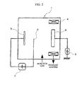
- FIG 2 is a schematic diagram showing a conventional arc ion plating apparatus.
- The surface-coated cBN-based sintered tool of the present invention will now be described in detail by way of examples.
- Cubic boron nitride (cBN) powder, Ti nitride (TiN) powder, Al powder and aluminum oxide (Al2O3) powder, all having a mean particle size in a range from 0.5 to 4 µm, were prepared as stock material powders, and were mixed in proportions shown in Table 1, using a ball mill in wet process for 80 hours. After drying, the mixture was pressed into a compact measuring 50 mm in diameter and 1.5 mm in thickness with a pressure of 120 MPa. The compact was sintered by heating at a temperature in a range from 900 to 1300°C for 60 minutes in vacuum of 1 Pa to obtain a presintered body for cutting edge. Separately, a support member made of a WC-based cemented carbide measuring 50 mm in diameter and 2 mm in thickness, and having the composition of 8% by mass of Co and the balance of WC was prepared. The presintered body and the support member were set in a conventional ultrahigh pressure sintering apparatus in the state where they are laid one upon another and ultrahigh pressure-sintered under the ordinary conditions of a pressure of 5 GPa, a temperature in a range from 1200 to 1400°C and a holding time of 0.8 hours. After sintering, the top and bottom surfaces of the resulting sintered body was polished using a diamond bonded abrasive. The sintered body was cut into an equilateral triangle-shaped tip having a side of 3 mm using a wire electric discharge machining apparatus. A insert body made of a WC-based cemented carbide having the composition of 5% by mass of Co, 5% by mass of TaC and the balance of WC, and measuring a configuration SNGA120412 specified in ISO standard (square measuring 4.76 mm in thickness and 12.7 mm in side) was prepared. The above-described cut tip of ultra-high pressure sintered body was soldered to the soldering portion (comer portion) of the above-described insert body using a soldering material ofAg alloy having the composition of 26% Cu, 5% Ti, 2.5% Ni and the balance ofAg. After a peripheral milling to from a body having a predetermined size, the cutting edge portion was subjected to honing process (width: 0.13 mm, angle: 25°), and then subjected to finish polishing. In accordance with the above described process, tool bodies A through J having a geometrical configuration of insert meeting SNGA120412 specified in ISO standard were produced.
- (a) Then the tool bodies A through J were subjected to ultrasonic cleaning in acetone. After drying, the tool bodies were set on a rotary table 20 along the circumference thereof at a predetermined radial distance from the center, in an arc
ion plating apparatus 10 as shown in FIGS. 1A and 1B. A metallic Ti for forming the thin layer B as the upper layer was placed as a cathode (evaporation source) 31 on one side, and as a cathode (evaporation source) 32 for forming the thin layer A as the upper layer and the lower layer, a Ti-Al alloy having the composition corresponding to the target composition shown in Table 2 was placed on the other side opposing each other with the rotary table 2 located therebetween. Thereference symbol 50 denotes a bias power source and thereference symbol - (b) While evacuating the apparatus to maintain the inside at a level of vacuum not higher than 0.1 Pa, the inside of the apparatus was heated to 500°C using a
heater 40 and an Ar gas was introduced into the apparatus to maintain a reaction atmosphere of 0.7 Pa and also a DC bias voltage of 200 V was applied to the tool body S that was spinning on the rotating table 20, thereby cleaning the surface of the tool body S by bombardment of argon ions, - (c) Then a nitrogen gas was introduced as a reaction gas into the apparatus to maintain a reaction atmosphere of 3 Pa, and a DC bias voltage of-100 V was applied to the tool body S that was spinning on the rotating table 20. At the same time, arc discharge was generated by supplying a current of 100 A between the Ti-Al alloy used for forming the thin layer A and the lower layer, and the
anode 62 thereby vapor depositing the [Ti, Al]N layer having the target composition and the target layer thickness shown in Table 2 was vapor deposited as the lower layer of the hard coating layer on the surface of the tool body S. - (d) Then a flow rate of a nitrogen gas as a reaction gas to be introduced into the apparatus was controlled to maintain a reaction atmosphere of 2 Pa, and a DC bias voltage in a range from -10 to -100 V was applied to the tool body S that was spinning on the rotating table 20. At the same time, arc discharge was generated by supplying a current of predetermined intensity in a range from 50 to 200 A between the
cathode 31 of the metallic Ti used for forming the thin layer B, and theanode 61, thereby forming the thin layer B of a predetermined thickness on the surface of the tool body. After forming the thin layer B, the arc discharge was stopped and a current of predetermined intensity in a range from 50 to 200 A was supplied between thecathode 32 of Ti-A1 alloy used for forming the thin layer A and the lower layer and theanode 62, thereby generating arc discharge and forming the thin layer A of the predetermined thickness. Then the arc discharge was stopped. Then again the formation of the thin layer B by means of arc discharge between thecathode 31 of the metallic Ti used for forming the thin layer B and theanode 61, and the formation of the thin layer A by means of arc discharge between thecathode 32 of a Ti-Al alloy used for forming the thin layer A and the lower later and theanode 62 were repeated alternately. Thus the upper layer having the structure consisting of the thin layer A and the thin layer B layered alternately having the target composition and the target thickness for single layer shown in Table 2 was formed on the surface of the tool body with the total thickness (average layer thickness) shown in Table 2 by vapor deposition. Thus each of the surface-coated cBN-based sintered tools according to the invention was produced. - For the purpose of comparison, the tool bodies A through J were subjected to ultrasonic cleaning in acetone. After drying, the tool bodies were set in an ordinary arc
ion plating apparatus 1 as shown in FIG. 2, and the Ti-Al alloy having the composition corresponding to the target composition shown in Tables 3 was disposed as a cathode (evaporation source) 3. While evacuating the apparatus to maintain the inside at a level of vacuum not higher than 0.1 Pa, the inside of the apparatus was heated to 500°C using aheater 4 and an Ar gas was introduced into the apparatus to maintain a reaction atmosphere of 0.7 Pa and also a DC bias voltage of-200 V was applied from abias voltage source 5 to the tool body S that was spinning on the rotating table 2, thereby cleaning the surface of the tool body by bombardment of argon ions. Then a nitrogen gas was introduced as a reaction gas into the apparatus to maintain a reaction atmosphere of 3 Pa, and the bias voltage applied to the tool body was -100 V, and arc discharge was generated between thecathode 3 made of the Ti-Al alloy and theanode 6 using anarc power source 7. Thus the surfaces of the tool bodies A through J were coated with the [Ti, AI]N layer having the target composition and target layer thickness shown in Tables 3, thereby producing conventional surface-coated cBN-basedsintered tools 1 to 10. - With respect to the cBN-based sintered material constituting the cutting insert body of various surface-coated cBN-based sintered tools thus obtained, the structure was observed using a scanning electron microscope. As a result, all cutting insert bodies exhibited the structure in which an ultrahigh pressure sintering reaction product is present at the interface between a cBN phase constituting substantially a disperse phase and a TiN phase constituting a continuous phase.
- Furthermore, the compositions of the surface coating layer was analyzed by energy-dispersive X-ray spectrometry using a transmission electron microscope, and all samples showed substantially the same compositions as the target compositions. Also the average layer thickness of the constituent layers of the hard coating layer was measured by observing the cross section with a transmission electron microscope. All samples showed substantially the same average layer thickness as the target thickness (mean of measurements at 5 points).
- Then various surface-coated cBN-based sintered tools were mounted at the distal end of a cutting tool made of tool steel by screwing a clamp fixture. The surface-coated cBN-based sintered tools Nos. 1 through 5 according to the invention and the conventional surface-coated cBN-based sintered tools Nos. 1 through 5 were subjected to high speed interrupted cutting operation test under the following cutting conditions A through C. Also the surface-coated cBN-based sintered tools Nos. 6 through 10 according to the invention and the conventional surface-coated cBN-based sintered tools Nos. 6 through 10 were subjected to high speed continuous cutting operation test under the following cutting conditions a through c.
- Interrupted high speed cutting operation test (normal cutting speed was 120 m/min.) in dry process of an alloy steel was performed under the following conditions:
- Workpiece: Carburized and hardened round bar of JIS SCM415 (hardness HRC61) with 4 grooves formed in longitudinal direction at equal spaces
- Cutting speed: 200 m/min.
- Depth of cut: 0.2 mm
- Feed: 0.15 mm/rev.
- Cutting time: 6 minutes
- Interrupted high speed cutting operation test (normal cutting speed was 120 m/min.) in dry process of a chrome steel was performed under the following conditions:
- Workpiece: Carburized and hardened round bar of JIS SCr420 (hardness: HRC60) with 4 grooves formed in longitudinal direction at equal spaces
- Cutting speed; 210 m/min.
- Depth of cut: 0.15 mm
- Feed: 0.12 mm/rev.
- Cutting time: 6 minutes
- Interrupted high speed cutting operation test (normal cutting speed was 150 m/min.) in dry process of a bearing steel was performed under the following conditions:
- Workpiece: Hardened round bar af JIS SUJ2 (hardness: HRC61) with 4 grooves formed in longitudinal direction at equal spaces.
- Cutting speed: 240 m/min.
- Depth of cut: 0.16 mm
- Feed: 0.10 mm/rev.
- Cutting time: 6 minutes
- Continuous high speed cutting operation test (normal cutting speed was 200 m/min.) in dry process of an alloy steel was performed under the following conditions:
- Workpiece; Carburized and hardened round bar of JIS SCM415 (hardness: HRC61)
- Cutting speed: 280 m/min.
- Depth of cut: 0.2 mm
- Feed: 0.10 mm/rev.
- Cutting time; 8 minutes
- Continuous high speed cutting operation test (normal cutting speed was 160 m/min.) in dry process of a chrome steel was performed under the following conditions:
- Workpiece: Carburized and hardened round bar of JIS SCr420 (hardness: HRC60)
- Cutting speed: 250 m/min.
- Depth of cut: 0.2 mm
- Feed: 0.1 mm/rev,
- Cutting time: 8 minutes
- Continuous high speed cutting operation test (normal cutting speed was 150 m/mm.) in dry process of a bearing steel was performed under the following conditions:
- Workpiece: Hardened round rod ofJIS SUJ2 (hardness HRC61)
- Cutting speed: 220 m/min.
- Depth of cut: 0.2 mm
- Feed: 0.1 mm/rev.
- Cutting time: 8 minutes
- Flank wear width (mm) of the cutting tool edge and surface finish (arithmetic mean height (Ra (µm))according to JIS B0601-2001) of workpiece were measured in every run of the cutting tests described above. The results are shown in Table 4.

- The results shown in Tables 2 through 4 obviously show the following effects of the invention. All the surface-coated cBN-based sintered tools according to the present invention had the hard coating layer comprising: the lower layer having the average layer thickness in a range from 1.5 to 3 µm; and the upper layer of the average layer thickness (total thickness) in a range from 0.3 to 3 µm, consisting of the thin layer A and the thin layer B each having the average layer thickness in a range from 0.05 to 0,3 µm layered alternately one on another. In each of the surface-coated cBN-based sintered tools of the invention, since the lower layer is provided with excellent heat resistance, high-temperature strength and high-temperature hardness, and the upper layer is provided with excellent heat resistance and high-temperature hardness as well as more excellent high-temperature strength and shock-resistant strength, the hard coating layer combined these excellent characteristics, and therefore can exhibit excellent wear resistance and ensure excellent surface finish of workpieces without causing edge notching and chipping even in a high speed cutting operation of a hardened steel, for example, hardened steel such as alloy steel or bearing steel. In contrast, the conventional surface-coated cBN-based sintered tools having the hard coating layer comprising [Ti, Al]N layer of the single phase structure, caused edge notching or chipping at the cutting edge because of insufficient high-temperature strength and shock-resistant strength of the hard coating layer, and also cannot maintain surface finish of workpieces and it is apparent that tool life will end in a relatively short period of time.
- As described above, as well as in a machining of various steels and cast irons under ordinary cutting conditions, even in a high speed continuous cutting operation or a high speed interrupted cutting operation of a hardened steel accompanied with generation of high heat and imposition of drastically large mechanical load intermittently and impulsively on a cutting edge, the surface-coated cBN-based sintered tool of the present invention is excellent in edge notching resistance exhibited by the hard coating layer, maintains excellent surface finish of work material over an extended period of time and exhibits excellent wear resistance. Thus the surface-coated cBN-based sintered tool of the present invention can sufficiently allows for labor saving, energy saving and cost reduction in metal cutting operations and contributes to the enhancement of performance of cutting apparatus.
- While preferred embodiments of the invention have been described and illustrated above, it should be understood that these are exemplary of the invention and are not to be considered limiting. Additions, omissions, substitutions and other modifications can be made without departing from the spirit or scope of the present invention. Accordingly, the invention is not considered as being limited by the foregoing description, and is only limited by the scope of the appended claims.
| Type | Symbol of tool body | Hard coating layer | ||||||||||
| Lower layer | Upper layer | |||||||||||
| Thin layer A | Thin layer B | Total thickness of upper layer (µm) | ||||||||||
| Target composition (atomic ratio) | Target thickness (µm) | Target composition (atomic ratio) | Target thickness of one layer (µm) | Target thickness of one layer (µm) | ||||||||
| Ti | Al | N | Ti | Al | N | |||||||
| Inventive surface- coated cBN-based sintered tool | 1 | A | 0.60 | 0.40 | 1.00 | 1.5 | 0.60 | 0.40 | 1.00 | 0.05 | 0.05 | 3.0 |
| 2 | B | 0.55 | 0.45 | 1.00 | 2.2 | 0.55 | 0.45 | 1.00 | 0.06 | 0.1 | 0.48 | |
| 3 | C | 0.52 | 0.48 | 1.00 | 3.0 | 0.52 | 0.48 | 1.00 | 0.05 | 0.3 | 1.75 | |
| 4 | D | 0.48 | 0.52 | 1.00 | 1.6 | 0.48 | 0.52 | 1.00 | 03 | 0.1 | 1.2 | |
| 5 | E | 0.45 | 0.55 | 1.00 | 2.6 | 0.45 | 0.55 | 1.00 | 0.15 | 0.2 | 1.05 | |
| 6 | F | 0.60 | 0.40 | 1.00 | 1.5 | 0.60 | 0.40 | 1.00 | 0.05 | 0.05 | 0.5 | |
| 7 | G | 0.55 | 0.45 | 1.00 | 2.2 | 0.55 | 0.45 | 1.00 | 0.06 | 0.1 | 0.48 | |
| 8 | H | 0.52 | 0.48 | 1.00 | 3.0 | 0.52 | 0.48 | 1.00 | 0.05 | 0.1 | 0.3 | |
| 9 | I | 0.48 | 0.52 | 1.00 | 1.6 | 0.48 | 0.52 | 1.00 | 0.3 | 0.1 | 1.2 | |
| 10 | J | 0.45 | 0.55 | 1.00 | 2.6 | 0.45 | 0.55 | 1.00 | 0.15 | 0.2 | 1.05 | |
| Type | Symbol of tool body | Hard coating layer | ||||
| Target composition (atomic ratio) | Target thickness (µm) | |||||
| Ti | Al | N | ||||
| Conventional surface-coated cBN-based sintered tool | 1 | A | 0.60 | 0.40 | 1.00 | 2.0 |
| 2 | B | 0.55 | 0.45 | 1.00 | 2.6 | |
| 3 | C | 0.52 | 0.48 | 1.00 | 3.3 | |
| 4 | D | 0.48 | 0.52 | 1.00 | 2.8 | |
| 5 | E | 0.45 | 0.55 | 1.00 | 6.0 | |
| 6 | F | 0.60 | 0.40 | 1.00 | 2.0 | |
| 7 | G | 0.55 | 0.45 | 1.00 | 2.6 | |
| 8 | H | 0.52 | 0.48 | 1.00 | 3.3 | |
| 9 | I | 0.48 | 0.52 | 1.00 | 2.8 | |
| 10 | J | 0.45 | 0.55 | 1.00 | 3.8 | |
| Type | Cutting conditions (A) | Cutting conditions (B) | Cutting conditions (C) | ||||
| Width of flank wear (mm) | Surface finish [Ra (µm)] | Width of flank wear (mm) | Surface finish [Ra (µm)] | Width of flank wear (mm) | Surface finish [Ra (µm)] | ||
| Inventive surface- coated cBN- based sintered tool | 1 | 0.11 | 1.2 | 0.11 | 0.9 | 0.09 | 0.8 |
| 2 | 0.10 | 1.0 | 0.12 | 0.8 | 0.08 | 0.8 | |
| 3 | 0.09 | 1.1 | 0.11 | 0.8 | 0.12 | 0.9 | |
| 4 | 1.09 | 1.0 | 0.09 | 0.7 | 0.12 | 1.0 | |
| 5 | 1.12 | 1.3 | 0.10 | 0.9 | 0.10 | 0.9 | |
| Cutting conditions (a) | Cutting conditions (b) | Cutting conditions (c) | |||||
| Width of flank wear (mm) | Surface finish [Ra (µm)] | Width of flank wear (mm) | Surface finish [Ra (µm)] | Width of flank wear (mm) | Surface finish [Ra (µm)] | ||
| 6 | 0.11 | 0.5 | 0.11 | 0.6 | 0.12 | 0.5 | |
| 7 | 0.12 | 0.6 | 0.08 | 0.5 | 0.10 | 0.6 | |
| 8 | 0.09 | 0.6 | 0.07 | 0.6 | 0.08 | 0.8 | |
| 9 | 0.12 | 0.6 | 0.10 | 0.7 | 0.10 | 0.6 | |
| 10 | 0.10 | 0.5 | 0.11 | 0.6 | 0.12 | 0.5 | |
| Conventional surface-coated cBN-based sintered tool | 1 | 1 min.** | - | 1 mb.** | - | 0.5 mm.** | - |
| 2 | 2mm.** | - | 2 min.** | - | 1 mm.** | - | |
| 3 | 1.5 min.** | - | 1 min. ** | - | 0.5 min.** | - | |
| 4 | 1 min.** | - | 0.5 min.** | - | 1.5 min.** | - | |
| 5 | 0.5 mm.** | - | 1 min.** | - | 1 min. ** | - | |
| Cutting conditions (a) | Cutting conditions (b) | Cutting conditions (c) | |||||
| Width of flank wear (mm) | Surface finish [Ra(µm)] | Width of flank wear (mm) | Surface finish [Ra(µm)] | Width of flank wear (mm) | Surface finish [Ra(µm)] | ||
| 6 | 0-10* | 1.5 | 0.12* | 1.8 | 0,12* | 1.6 | |
| 7 | 0.10* | 2.0 | 5min.** | - | 5 min.** | - | |
| 8 | 0.12* | 1.7 | 0.10* | 2.0 | 0.12* | 2.5 | |
| 9 | 4 min.** | - | 3 mill** | - | 0.10* | 1.8 | |
| 10 | 5 min.** | - | 5 min. ** | - | 6 min.** | - | |
| In the table, the symbol* means tools in which edge notching occurred, while the symbol** means the cutting time (min.) of tools in which tool life ended due to edge notching and chipping. |
Claims (1)
- A cutting tool made of surface-coated cubic boron nitride-based ultrahigh pressure sintered material, comprising:a main body consisting of ultrahigh pressure sintered material formed by ultrahigh pressure sintering of a compact having a composition of, in mass %, 13 to 30% of titanium nitride, 6.5 to 18 % of aluminum and/or aluminum oxide and a balance of boron nitride,under an observation using a scanning electron microscope, the main body showing a texture such that an ultrahigh pressure sintering reaction product is present at the interface between a cubic boron nitride phase constituting a disperse phase and a titanium nitride phase constituting a continuous phase; anda hard coating that is vapor-deposited on the surface of the main body and has a lower layer of an average layer thickness in a range from 1,5 to 3 µm and an upper layer of an average layer thickness in a range from 0.3 to 3 µm, wherein:the lower layer of the hard coating layer consists of a vapor-deposited composite nitride af Ti and Al having the composition of [Ti1-XAlX]N, where X is in a range from 0.40 to 0,60 in an atomic ratio; andthe upper layer of the hard coating layer is vapor-deposited on the surface of the upper layer, comprises at least one thin layer A consisting of a composite nitride of Ti and Al having the composition of [Ti1-XAlX]N, where X is in a range from 0.40 to 0.60 in an atomic ratio, and at least one thin layer B consisting of a Ti nitride (TiN), and has a structure in which the thin layer A and the thin layer B layered alternately such that average layer thickness of each single layer is in a range of 0.05 to 0.3 µm.
Applications Claiming Priority (2)
| Application Number | Priority Date | Filing Date | Title |
|---|---|---|---|
| JP2005370000 | 2005-12-22 | ||
| JP2006142108A JP4985919B2 (en) | 2005-12-22 | 2006-05-22 | Cutting tool made of surface-coated cubic boron nitride-based ultra-high pressure sintered material that provides excellent long-term surface accuracy in high-speed cutting of hardened steel |
Publications (2)
| Publication Number | Publication Date |
|---|---|
| EP1801260A1 true EP1801260A1 (en) | 2007-06-27 |
| EP1801260B1 EP1801260B1 (en) | 2011-02-16 |
Family
ID=37781607
Family Applications (1)
| Application Number | Title | Priority Date | Filing Date |
|---|---|---|---|
| EP06126326A Active EP1801260B1 (en) | 2005-12-22 | 2006-12-18 | Cutting tool made of surface-coated cubic boron nitride-based ultrahigh pressure sintered material |
Country Status (6)
| Country | Link |
|---|---|
| US (1) | US8017225B2 (en) |
| EP (1) | EP1801260B1 (en) |
| JP (1) | JP4985919B2 (en) |
| CN (1) | CN1986487B (en) |
| AT (1) | ATE498706T1 (en) |
| DE (1) | DE602006020108D1 (en) |
Cited By (4)
| Publication number | Priority date | Publication date | Assignee | Title |
|---|---|---|---|---|
| EP1867754A1 (en) * | 2006-05-26 | 2007-12-19 | Mitsubishi Materials Corporation | Cutting tool made of surface-coated cubic boron nitride-based ultra-high-pressure sintered material |
| US8017225B2 (en) | 2005-12-22 | 2011-09-13 | Mitsubishi Materials Corporation | Cutting tool made of surface-coated cubic boron nitride-based ultrahigh pressure sintered material |
| DE102012000540A1 (en) | 2011-02-07 | 2012-08-09 | Kennametal Inc. | Coating of cubic aluminum titanium nitride and process for its preparation |
| CN104053517A (en) * | 2012-01-10 | 2014-09-17 | 住友电工硬质合金株式会社 | Diamond-coated tool |
Families Citing this family (20)
| Publication number | Priority date | Publication date | Assignee | Title |
|---|---|---|---|---|
| KR100876366B1 (en) * | 2008-04-24 | 2008-12-31 | 한국야금 주식회사 | Multilayer with antiwear and antishockcoated to cutting tool |
| JP2011051060A (en) * | 2009-09-02 | 2011-03-17 | Mitsubishi Materials Corp | Surface coating cutting tool |
| US8277958B2 (en) * | 2009-10-02 | 2012-10-02 | Kennametal Inc. | Aluminum titanium nitride coating and method of making same |
| CN102061466B (en) * | 2009-11-12 | 2014-07-30 | 三菱综合材料株式会社 | Surface coated cutting tool |
| JP5447844B2 (en) * | 2010-03-19 | 2014-03-19 | 三菱マテリアル株式会社 | High toughness cubic boron nitride based ultra high pressure sintered material and cutting tool |
| CN102294854B (en) * | 2010-06-24 | 2014-07-09 | 鸿富锦精密工业(深圳)有限公司 | Hard coating and preparation method thereof and covering element having hard coating |
| JP5574277B2 (en) * | 2010-10-29 | 2014-08-20 | 三菱マテリアル株式会社 | Cutting tool made of surface-coated cubic boron nitride-based ultra-high pressure sintered material with excellent peeling resistance |
| US9476114B2 (en) | 2012-08-03 | 2016-10-25 | Walter Ag | TiAlN-coated tool |
| DE102012107129A1 (en) * | 2012-08-03 | 2014-02-06 | Walter Ag | TiAIN coated tool |
| US9103036B2 (en) | 2013-03-15 | 2015-08-11 | Kennametal Inc. | Hard coatings comprising cubic phase forming compositions |
| US9896767B2 (en) | 2013-08-16 | 2018-02-20 | Kennametal Inc | Low stress hard coatings and applications thereof |
| US9168664B2 (en) | 2013-08-16 | 2015-10-27 | Kennametal Inc. | Low stress hard coatings and applications thereof |
| CN103553637B (en) * | 2013-11-06 | 2015-01-21 | 禹州市和汇超硬材料有限公司 | Cubic boron nitride glomerocryst composite with surface coating structure and preparation method thereof |
| JP5879664B2 (en) * | 2013-12-26 | 2016-03-08 | 住友電工ハードメタル株式会社 | Cutting tools |
| JP6637664B2 (en) | 2014-03-28 | 2020-01-29 | 三菱マテリアル株式会社 | Cubic boron nitride sintered compact cutting tool |
| CN104030690B (en) * | 2014-06-09 | 2015-10-07 | 河海大学 | A kind of preparation method of titanium nitride-TiB2-cubic boron nitride material |
| CN107586116B (en) * | 2017-03-07 | 2020-09-11 | 鲁东大学 | Preparation method of layered ceramic cutter based on shock wave conduction theory |
| US10570501B2 (en) | 2017-05-31 | 2020-02-25 | Kennametal Inc. | Multilayer nitride hard coatings |
| CN107740067B (en) * | 2017-09-28 | 2020-03-13 | 哈尔滨工业大学 | Chemical vapor deposition device and method for micro-cutter diamond coating |
| NL2021137B1 (en) * | 2018-06-15 | 2019-12-20 | Boschman Tech Bv | Sintering Process Product Carrier |
Citations (6)
| Publication number | Priority date | Publication date | Assignee | Title |
|---|---|---|---|---|
| EP0709353A2 (en) * | 1994-10-27 | 1996-05-01 | Sumitomo Electric Industries, Limited | Hard composite material for tools |
| US20010003569A1 (en) * | 1999-12-03 | 2001-06-14 | Michiko Ota | Coated PCBN cutting tools |
| EP1312593A2 (en) * | 2001-11-19 | 2003-05-21 | Muncie Power Products, Inc. | Dual coated cubic boron nitride cutting tool and method of employing same |
| US6599062B1 (en) * | 1999-06-11 | 2003-07-29 | Kennametal Pc Inc. | Coated PCBN cutting inserts |
| EP1382709A1 (en) * | 2002-07-11 | 2004-01-21 | Sumitomo Electric Industries, Ltd. | Coated tool |
| EP1470879A1 (en) * | 2002-01-21 | 2004-10-27 | Mitsubishi Materials Kobe Tools Corporation | Surface coated cutting tool member having hard coating layer exhibiting excellent abrasion resistance in high-speed cutting, and method for forming said hard coating layer on surface of cutting tool |
Family Cites Families (24)
| Publication number | Priority date | Publication date | Assignee | Title |
|---|---|---|---|---|
| JPS59153851A (en) | 1983-02-19 | 1984-09-01 | Tatsuro Kuratomi | Production of sintered body of cubic boron nitride combining alumina and titanium nitride |
| DE69319531T2 (en) * | 1992-10-12 | 1999-04-15 | Sumitomo Electric Industries | Ultra thin film laminate |
| JP2638406B2 (en) * | 1992-10-26 | 1997-08-06 | 神鋼コベルコツール株式会社 | Wear resistant multilayer hard film structure |
| JP3460288B2 (en) | 1994-01-21 | 2003-10-27 | 住友電気工業株式会社 | Surface coating member with excellent wear resistance |
| JPH07300649A (en) | 1994-04-27 | 1995-11-14 | Kobe Steel Ltd | Hard film excellent in wear resistance and oxidation resistance and high hardness member |
| JP2793773B2 (en) * | 1994-05-13 | 1998-09-03 | 神鋼コベルコツール株式会社 | Hard coating, hard coating tool and hard coating member excellent in wear resistance |
| DE69519341T2 (en) | 1994-08-01 | 2001-03-15 | Sumitomo Electric Industries | Superhard composite material for tools |
| JP3743984B2 (en) * | 1994-08-01 | 2006-02-08 | 住友電気工業株式会社 | Composite high hardness material for tools |
| JPH08206902A (en) * | 1994-12-01 | 1996-08-13 | Sumitomo Electric Ind Ltd | Sintered body tip for cutting and its manufacture |
| JP3488526B2 (en) | 1994-12-14 | 2004-01-19 | 三菱マテリアル神戸ツールズ株式会社 | Hard coatings and hard coatings with excellent wear resistance |
| JP3374599B2 (en) | 1995-06-01 | 2003-02-04 | 住友電気工業株式会社 | Hard wear-resistant composite coated cutting tool |
| US5722803A (en) * | 1995-07-14 | 1998-03-03 | Kennametal Inc. | Cutting tool and method of making the cutting tool |
| DE59709451D1 (en) * | 1996-09-03 | 2003-04-10 | Unaxis Balzers Ag | WEAR PROTECTION-COATED WORKPIECE |
| SE518145C2 (en) * | 1997-04-18 | 2002-09-03 | Sandvik Ab | Multilayer coated cutting tool |
| JP4185172B2 (en) * | 1997-06-19 | 2008-11-26 | 住友電工ハードメタル株式会社 | Coated hard tool |
| CA2285460A1 (en) * | 1998-02-04 | 1999-08-12 | Osg Corporation | Hard multilayer coated tool having increased toughness |
| JP3599628B2 (en) | 2000-02-25 | 2004-12-08 | 株式会社タンガロイ | Composite hard film coated member |
| JP3637882B2 (en) * | 2000-08-31 | 2005-04-13 | 住友電気工業株式会社 | Surface coated boron nitride sintered body tool |
| JP5100927B2 (en) * | 2001-01-30 | 2012-12-19 | 昭和電工株式会社 | Method for producing cubic boron nitride sintered body |
| JP3700658B2 (en) | 2002-02-26 | 2005-09-28 | 三菱マテリアル株式会社 | Cutting tool made of surface-coated cubic boron nitride based sintered material that exhibits excellent chipping resistance with a hard coating layer in intermittent heavy cutting |
| JP4284503B2 (en) * | 2003-05-21 | 2009-06-24 | 三菱マテリアル株式会社 | Cutting tool made of surface-coated cubic boron nitride-based sintered material that exhibits excellent chipping resistance with a hard coating layer in high-speed heavy cutting |
| CN100419117C (en) * | 2004-02-02 | 2008-09-17 | 株式会社神户制钢所 | Hard laminated film, method of manufacturing the same and film-forming device |
| JP4702520B2 (en) * | 2005-02-14 | 2011-06-15 | 三菱マテリアル株式会社 | Cutting tool made of surface-coated cemented carbide that provides excellent wear resistance with a hard coating layer in high-speed cutting of hardened steel |
| JP4985919B2 (en) | 2005-12-22 | 2012-07-25 | 三菱マテリアル株式会社 | Cutting tool made of surface-coated cubic boron nitride-based ultra-high pressure sintered material that provides excellent long-term surface accuracy in high-speed cutting of hardened steel |
-
2006
- 2006-05-22 JP JP2006142108A patent/JP4985919B2/en active Active
- 2006-12-18 EP EP06126326A patent/EP1801260B1/en active Active
- 2006-12-18 AT AT06126326T patent/ATE498706T1/en not_active IP Right Cessation
- 2006-12-18 DE DE602006020108T patent/DE602006020108D1/en active Active
- 2006-12-20 CN CN2006101690847A patent/CN1986487B/en active Active
- 2006-12-20 US US11/613,323 patent/US8017225B2/en active Active
Patent Citations (6)
| Publication number | Priority date | Publication date | Assignee | Title |
|---|---|---|---|---|
| EP0709353A2 (en) * | 1994-10-27 | 1996-05-01 | Sumitomo Electric Industries, Limited | Hard composite material for tools |
| US6599062B1 (en) * | 1999-06-11 | 2003-07-29 | Kennametal Pc Inc. | Coated PCBN cutting inserts |
| US20010003569A1 (en) * | 1999-12-03 | 2001-06-14 | Michiko Ota | Coated PCBN cutting tools |
| EP1312593A2 (en) * | 2001-11-19 | 2003-05-21 | Muncie Power Products, Inc. | Dual coated cubic boron nitride cutting tool and method of employing same |
| EP1470879A1 (en) * | 2002-01-21 | 2004-10-27 | Mitsubishi Materials Kobe Tools Corporation | Surface coated cutting tool member having hard coating layer exhibiting excellent abrasion resistance in high-speed cutting, and method for forming said hard coating layer on surface of cutting tool |
| EP1382709A1 (en) * | 2002-07-11 | 2004-01-21 | Sumitomo Electric Industries, Ltd. | Coated tool |
Cited By (5)
| Publication number | Priority date | Publication date | Assignee | Title |
|---|---|---|---|---|
| US8017225B2 (en) | 2005-12-22 | 2011-09-13 | Mitsubishi Materials Corporation | Cutting tool made of surface-coated cubic boron nitride-based ultrahigh pressure sintered material |
| EP1867754A1 (en) * | 2006-05-26 | 2007-12-19 | Mitsubishi Materials Corporation | Cutting tool made of surface-coated cubic boron nitride-based ultra-high-pressure sintered material |
| US7939186B2 (en) | 2006-05-26 | 2011-05-10 | Mitsubishi Materials Corporation | Cutting tool made of surface-coated cubic boron nitride-based ultra-high-pressure sintered material |
| DE102012000540A1 (en) | 2011-02-07 | 2012-08-09 | Kennametal Inc. | Coating of cubic aluminum titanium nitride and process for its preparation |
| CN104053517A (en) * | 2012-01-10 | 2014-09-17 | 住友电工硬质合金株式会社 | Diamond-coated tool |
Also Published As
| Publication number | Publication date |
|---|---|
| CN1986487B (en) | 2012-09-05 |
| US8017225B2 (en) | 2011-09-13 |
| DE602006020108D1 (en) | 2011-03-31 |
| ATE498706T1 (en) | 2011-03-15 |
| CN1986487A (en) | 2007-06-27 |
| JP4985919B2 (en) | 2012-07-25 |
| JP2007190668A (en) | 2007-08-02 |
| US20070148496A1 (en) | 2007-06-28 |
| EP1801260B1 (en) | 2011-02-16 |
Similar Documents
| Publication | Publication Date | Title |
|---|---|---|
| EP1801260B1 (en) | Cutting tool made of surface-coated cubic boron nitride-based ultrahigh pressure sintered material | |
| EP1867754B1 (en) | Cutting tool made of surface-coated cubic boron nitride-based ultra-high-pressure sintered material | |
| JP5418833B2 (en) | Cutting tool made of surface coated cubic boron nitride based ultra high pressure sintered material | |
| JP4883475B2 (en) | Cutting tool made of surface-coated cubic boron nitride-based ultra-high pressure sintered material that exhibits excellent wear resistance in high-speed cutting of hardened steel | |
| JP2008254159A (en) | Surface-coated cutting tool made of cubic boron nitride group ultrahigh-pressure sintered material | |
| JP4883473B2 (en) | Cutting tool made of surface-coated cubic boron nitride-based ultra-high pressure sintered material that exhibits excellent chipping resistance in hard cutting of hardened steel | |
| JP4807575B2 (en) | Cutting tool made of surface-coated cubic boron nitride-based ultra-high pressure sintered material that exhibits excellent wear resistance in high-speed cutting of hardened steel | |
| JP4883480B2 (en) | Cutting tool made of surface-coated cubic boron nitride-based ultra-high pressure sintered material that exhibits excellent fracture resistance in high-speed continuous cutting of hard difficult-to-cut materials | |
| JP4985914B2 (en) | Cutting tool made of super-high pressure sintered material with surface-coated cubic boron nitride based on excellent finish surface accuracy | |
| JP4883472B2 (en) | Cutting tool made of surface-coated cubic boron nitride-based ultra-high pressure sintered material that exhibits excellent chipping resistance in hard cutting of hardened steel | |
| JP4883478B2 (en) | Cutting tool made of surface-coated cubic boron nitride-based ultra-high pressure sintered material that exhibits excellent finished surface accuracy over a long period of time in high-speed continuous cutting of hard difficult-to-cut materials | |
| JP4883471B2 (en) | Cutting tool made of surface-coated cubic boron nitride-based ultra-high pressure sintered material that exhibits excellent chipping resistance in hard cutting of hardened steel | |
| JP4883477B2 (en) | Cutting tool made of surface-coated cubic boron nitride-based ultra-high pressure sintered material that exhibits excellent fracture resistance in high-speed intermittent cutting of high-hardness steel | |
| JP5402155B2 (en) | Cutting tool made of surface coated cubic boron nitride based ultra high pressure sintered material | |
| JP2008302439A (en) | Cutting tool made of surface coated cubic boron nitride-base very high pressure sintered material | |
| JP2008018505A (en) | Cutting tool made of surface coated cubic boron nitride-base very high pressure sintered material exhibiting excellent chipping resistance in high-speed cutting hard material hard to cut | |
| JP4883479B2 (en) | Cutting tool made of surface-coated cubic boron nitride-based ultra-high pressure sintered material that exhibits excellent fracture resistance in high-speed intermittent cutting of high-hardness steel | |
| JP4748446B2 (en) | Cutting tool made of surface-coated cubic boron nitride-based ultra-high pressure sintered material that exhibits excellent chipping resistance when cutting hard difficult-to-cut materials | |
| JP4748445B2 (en) | Cutting tool made of super-high-pressure sintered material with surface-coated cubic boron nitride that exhibits excellent chipping resistance with a hard coating layer in intermittent cutting of high-hardness steel | |
| JP4883474B2 (en) | Cutting tool made of surface-coated cubic boron nitride-based ultra-high pressure sintered material that exhibits excellent wear resistance in high-speed cutting of hardened steel | |
| JP4748447B2 (en) | Cutting tool made of surface-coated cubic boron nitride-based ultra-high pressure sintered material that exhibits excellent chipping resistance in high-speed cutting of hard difficult-to-cut materials | |
| JP2008302438A (en) | Cutting tool made of surface coated cubic boron nitride-base very high pressure sintered material | |
| JP2008018504A (en) | Cutting tool made of surface coated cubic boron nitride-base very high pressure sintered material exhibiting excellent chipping resistance in high-speed cutting hard material hard to cut | |
| JP5472678B2 (en) | Cutting tool made of surface coated cubic boron nitride based ultra high pressure sintered material | |
| JP2012101358A (en) | Cutting tool made of surface-coated cubic boron nitride-based ultrahigh pressure sintered material exhibiting excellent finished surface accuracy in high-speed machining of high hardness steel over long period of time |
Legal Events
| Date | Code | Title | Description |
|---|---|---|---|
| PUAI | Public reference made under article 153(3) epc to a published international application that has entered the european phase |
Free format text: ORIGINAL CODE: 0009012 |
|
| AK | Designated contracting states |
Kind code of ref document: A1 Designated state(s): AT BE BG CH CY CZ DE DK EE ES FI FR GB GR HU IE IS IT LI LT LU LV MC NL PL PT RO SE SI SK TR |
|
| AX | Request for extension of the european patent |
Extension state: AL BA HR MK YU |
|
| 17P | Request for examination filed |
Effective date: 20070718 |
|
| RAP1 | Party data changed (applicant data changed or rights of an application transferred) |
Owner name: MITSUBISHI MATERIALS KOBE TOOLS CORPORATION Owner name: MITSUBISHI MATERIALS CORPORATION |
|
| 17Q | First examination report despatched |
Effective date: 20070816 |
|
| AKX | Designation fees paid |
Designated state(s): AT BE BG CH CY CZ DE DK EE ES FI FR GB GR HU IE IS IT LI LT LU LV MC NL PL PT RO SE SI SK TR |
|
| RAP1 | Party data changed (applicant data changed or rights of an application transferred) |
Owner name: MITSUBISHI MATERIALS CORPORATION |
|
| GRAP | Despatch of communication of intention to grant a patent |
Free format text: ORIGINAL CODE: EPIDOSNIGR1 |
|
| GRAS | Grant fee paid |
Free format text: ORIGINAL CODE: EPIDOSNIGR3 |
|
| GRAA | (expected) grant |
Free format text: ORIGINAL CODE: 0009210 |
|
| RIN1 | Information on inventor provided before grant (corrected) |
Inventor name: TAJIMA, ITSURO Inventor name: TAKAOKA, HIDEMITSU |
|
| AK | Designated contracting states |
Kind code of ref document: B1 Designated state(s): AT BE BG CH CY CZ DE DK EE ES FI FR GB GR HU IE IS IT LI LT LU LV MC NL PL PT RO SE SI SK TR |
|
| REG | Reference to a national code |
Ref country code: GB Ref legal event code: FG4D |
|
| REG | Reference to a national code |
Ref country code: CH Ref legal event code: EP |
|
| REG | Reference to a national code |
Ref country code: IE Ref legal event code: FG4D |
|
| REF | Corresponds to: |
Ref document number: 602006020108 Country of ref document: DE Date of ref document: 20110331 Kind code of ref document: P |
|
| REG | Reference to a national code |
Ref country code: DE Ref legal event code: R096 Ref document number: 602006020108 Country of ref document: DE Effective date: 20110331 |
|
| REG | Reference to a national code |
Ref country code: SE Ref legal event code: TRGR |
|
| REG | Reference to a national code |
Ref country code: NL Ref legal event code: T3 |
|
| REG | Reference to a national code |
Ref country code: ES Ref legal event code: FG2A Ref document number: 2358036 Country of ref document: ES Kind code of ref document: T3 Effective date: 20110420 |
|
| LTIE | Lt: invalidation of european patent or patent extension |
Effective date: 20110216 |
|
| PG25 | Lapsed in a contracting state [announced via postgrant information from national office to epo] |
Ref country code: LT Free format text: LAPSE BECAUSE OF FAILURE TO SUBMIT A TRANSLATION OF THE DESCRIPTION OR TO PAY THE FEE WITHIN THE PRESCRIBED TIME-LIMIT Effective date: 20110216 Ref country code: LV Free format text: LAPSE BECAUSE OF FAILURE TO SUBMIT A TRANSLATION OF THE DESCRIPTION OR TO PAY THE FEE WITHIN THE PRESCRIBED TIME-LIMIT Effective date: 20110216 Ref country code: GR Free format text: LAPSE BECAUSE OF FAILURE TO SUBMIT A TRANSLATION OF THE DESCRIPTION OR TO PAY THE FEE WITHIN THE PRESCRIBED TIME-LIMIT Effective date: 20110517 Ref country code: PT Free format text: LAPSE BECAUSE OF FAILURE TO SUBMIT A TRANSLATION OF THE DESCRIPTION OR TO PAY THE FEE WITHIN THE PRESCRIBED TIME-LIMIT Effective date: 20110616 |
|
| PG25 | Lapsed in a contracting state [announced via postgrant information from national office to epo] |
Ref country code: AT Free format text: LAPSE BECAUSE OF FAILURE TO SUBMIT A TRANSLATION OF THE DESCRIPTION OR TO PAY THE FEE WITHIN THE PRESCRIBED TIME-LIMIT Effective date: 20110216 Ref country code: BE Free format text: LAPSE BECAUSE OF FAILURE TO SUBMIT A TRANSLATION OF THE DESCRIPTION OR TO PAY THE FEE WITHIN THE PRESCRIBED TIME-LIMIT Effective date: 20110216 Ref country code: PL Free format text: LAPSE BECAUSE OF FAILURE TO SUBMIT A TRANSLATION OF THE DESCRIPTION OR TO PAY THE FEE WITHIN THE PRESCRIBED TIME-LIMIT Effective date: 20110216 Ref country code: BG Free format text: LAPSE BECAUSE OF FAILURE TO SUBMIT A TRANSLATION OF THE DESCRIPTION OR TO PAY THE FEE WITHIN THE PRESCRIBED TIME-LIMIT Effective date: 20110516 Ref country code: CY Free format text: LAPSE BECAUSE OF FAILURE TO SUBMIT A TRANSLATION OF THE DESCRIPTION OR TO PAY THE FEE WITHIN THE PRESCRIBED TIME-LIMIT Effective date: 20110216 Ref country code: SI Free format text: LAPSE BECAUSE OF FAILURE TO SUBMIT A TRANSLATION OF THE DESCRIPTION OR TO PAY THE FEE WITHIN THE PRESCRIBED TIME-LIMIT Effective date: 20110216 Ref country code: FI Free format text: LAPSE BECAUSE OF FAILURE TO SUBMIT A TRANSLATION OF THE DESCRIPTION OR TO PAY THE FEE WITHIN THE PRESCRIBED TIME-LIMIT Effective date: 20110216 |
|
| PG25 | Lapsed in a contracting state [announced via postgrant information from national office to epo] |
Ref country code: EE Free format text: LAPSE BECAUSE OF FAILURE TO SUBMIT A TRANSLATION OF THE DESCRIPTION OR TO PAY THE FEE WITHIN THE PRESCRIBED TIME-LIMIT Effective date: 20110216 Ref country code: DK Free format text: LAPSE BECAUSE OF FAILURE TO SUBMIT A TRANSLATION OF THE DESCRIPTION OR TO PAY THE FEE WITHIN THE PRESCRIBED TIME-LIMIT Effective date: 20110216 |
|
| PG25 | Lapsed in a contracting state [announced via postgrant information from national office to epo] |
Ref country code: SK Free format text: LAPSE BECAUSE OF FAILURE TO SUBMIT A TRANSLATION OF THE DESCRIPTION OR TO PAY THE FEE WITHIN THE PRESCRIBED TIME-LIMIT Effective date: 20110216 Ref country code: CZ Free format text: LAPSE BECAUSE OF FAILURE TO SUBMIT A TRANSLATION OF THE DESCRIPTION OR TO PAY THE FEE WITHIN THE PRESCRIBED TIME-LIMIT Effective date: 20110216 Ref country code: RO Free format text: LAPSE BECAUSE OF FAILURE TO SUBMIT A TRANSLATION OF THE DESCRIPTION OR TO PAY THE FEE WITHIN THE PRESCRIBED TIME-LIMIT Effective date: 20110216 |
|
| PLBE | No opposition filed within time limit |
Free format text: ORIGINAL CODE: 0009261 |
|
| STAA | Information on the status of an ep patent application or granted ep patent |
Free format text: STATUS: NO OPPOSITION FILED WITHIN TIME LIMIT |
|
| 26N | No opposition filed |
Effective date: 20111117 |
|
| REG | Reference to a national code |
Ref country code: DE Ref legal event code: R097 Ref document number: 602006020108 Country of ref document: DE Effective date: 20111117 |
|
| PG25 | Lapsed in a contracting state [announced via postgrant information from national office to epo] |
Ref country code: MC Free format text: LAPSE BECAUSE OF NON-PAYMENT OF DUE FEES Effective date: 20111231 |
|
| REG | Reference to a national code |
Ref country code: CH Ref legal event code: PL |
|
| REG | Reference to a national code |
Ref country code: IE Ref legal event code: MM4A |
|
| PG25 | Lapsed in a contracting state [announced via postgrant information from national office to epo] |
Ref country code: IE Free format text: LAPSE BECAUSE OF NON-PAYMENT OF DUE FEES Effective date: 20111218 Ref country code: CH Free format text: LAPSE BECAUSE OF NON-PAYMENT OF DUE FEES Effective date: 20111231 Ref country code: LI Free format text: LAPSE BECAUSE OF NON-PAYMENT OF DUE FEES Effective date: 20111231 |
|
| PG25 | Lapsed in a contracting state [announced via postgrant information from national office to epo] |
Ref country code: LU Free format text: LAPSE BECAUSE OF NON-PAYMENT OF DUE FEES Effective date: 20111218 |
|
| PG25 | Lapsed in a contracting state [announced via postgrant information from national office to epo] |
Ref country code: IS Free format text: LAPSE BECAUSE OF FAILURE TO SUBMIT A TRANSLATION OF THE DESCRIPTION OR TO PAY THE FEE WITHIN THE PRESCRIBED TIME-LIMIT Effective date: 20110216 |
|
| PG25 | Lapsed in a contracting state [announced via postgrant information from national office to epo] |
Ref country code: TR Free format text: LAPSE BECAUSE OF FAILURE TO SUBMIT A TRANSLATION OF THE DESCRIPTION OR TO PAY THE FEE WITHIN THE PRESCRIBED TIME-LIMIT Effective date: 20110216 |
|
| PG25 | Lapsed in a contracting state [announced via postgrant information from national office to epo] |
Ref country code: HU Free format text: LAPSE BECAUSE OF FAILURE TO SUBMIT A TRANSLATION OF THE DESCRIPTION OR TO PAY THE FEE WITHIN THE PRESCRIBED TIME-LIMIT Effective date: 20110216 |
|
| REG | Reference to a national code |
Ref country code: FR Ref legal event code: PLFP Year of fee payment: 10 |
|
| REG | Reference to a national code |
Ref country code: FR Ref legal event code: PLFP Year of fee payment: 11 |
|
| PGFP | Annual fee paid to national office [announced via postgrant information from national office to epo] |
Ref country code: ES Payment date: 20161213 Year of fee payment: 11 |
|
| REG | Reference to a national code |
Ref country code: FR Ref legal event code: PLFP Year of fee payment: 12 |
|
| REG | Reference to a national code |
Ref country code: ES Ref legal event code: FD2A Effective date: 20190703 |
|
| PG25 | Lapsed in a contracting state [announced via postgrant information from national office to epo] |
Ref country code: ES Free format text: LAPSE BECAUSE OF NON-PAYMENT OF DUE FEES Effective date: 20171219 |
|
| PGFP | Annual fee paid to national office [announced via postgrant information from national office to epo] |
Ref country code: SE Payment date: 20211221 Year of fee payment: 16 Ref country code: GB Payment date: 20211221 Year of fee payment: 16 Ref country code: FR Payment date: 20211224 Year of fee payment: 16 |
|
| PGFP | Annual fee paid to national office [announced via postgrant information from national office to epo] |
Ref country code: NL Payment date: 20211221 Year of fee payment: 16 |
|
| REG | Reference to a national code |
Ref country code: SE Ref legal event code: EUG |
|
| REG | Reference to a national code |
Ref country code: NL Ref legal event code: MM Effective date: 20230101 |
|
| GBPC | Gb: european patent ceased through non-payment of renewal fee |
Effective date: 20221218 |
|
| PG25 | Lapsed in a contracting state [announced via postgrant information from national office to epo] |
Ref country code: NL Free format text: LAPSE BECAUSE OF NON-PAYMENT OF DUE FEES Effective date: 20230101 |
|
| PG25 | Lapsed in a contracting state [announced via postgrant information from national office to epo] |
Ref country code: SE Free format text: LAPSE BECAUSE OF NON-PAYMENT OF DUE FEES Effective date: 20221219 Ref country code: GB Free format text: LAPSE BECAUSE OF NON-PAYMENT OF DUE FEES Effective date: 20221218 |
|
| PG25 | Lapsed in a contracting state [announced via postgrant information from national office to epo] |
Ref country code: FR Free format text: LAPSE BECAUSE OF NON-PAYMENT OF DUE FEES Effective date: 20221231 |
|
| PGFP | Annual fee paid to national office [announced via postgrant information from national office to epo] |
Ref country code: IT Payment date: 20231228 Year of fee payment: 18 Ref country code: DE Payment date: 20231214 Year of fee payment: 18 |