EP1800529B1 - Faucheuse - Google Patents
Faucheuse Download PDFInfo
- Publication number
- EP1800529B1 EP1800529B1 EP06025318A EP06025318A EP1800529B1 EP 1800529 B1 EP1800529 B1 EP 1800529B1 EP 06025318 A EP06025318 A EP 06025318A EP 06025318 A EP06025318 A EP 06025318A EP 1800529 B1 EP1800529 B1 EP 1800529B1
- Authority
- EP
- European Patent Office
- Prior art keywords
- mowing
- mowing machine
- machine according
- working
- pressure
- Prior art date
- Legal status (The legal status is an assumption and is not a legal conclusion. Google has not performed a legal analysis and makes no representation as to the accuracy of the status listed.)
- Active
Links
- 230000033001 locomotion Effects 0.000 claims description 25
- 230000001419 dependent effect Effects 0.000 claims description 2
- 238000010168 coupling process Methods 0.000 abstract description 6
- 238000005859 coupling reaction Methods 0.000 abstract description 4
- 239000012530 fluid Substances 0.000 abstract description 4
- 230000008878 coupling Effects 0.000 abstract description 3
- 230000005540 biological transmission Effects 0.000 description 13
- 238000004146 energy storage Methods 0.000 description 8
- 230000008901 benefit Effects 0.000 description 6
- 230000002706 hydrostatic effect Effects 0.000 description 6
- 239000000725 suspension Substances 0.000 description 5
- 230000000295 complement effect Effects 0.000 description 4
- 238000013461 design Methods 0.000 description 4
- 238000010586 diagram Methods 0.000 description 4
- 238000000034 method Methods 0.000 description 4
- 230000008569 process Effects 0.000 description 4
- 230000009471 action Effects 0.000 description 3
- 238000006243 chemical reaction Methods 0.000 description 3
- 230000006378 damage Effects 0.000 description 3
- 230000005484 gravity Effects 0.000 description 3
- 239000002689 soil Substances 0.000 description 3
- 230000008719 thickening Effects 0.000 description 3
- 230000001960 triggered effect Effects 0.000 description 3
- 208000027418 Wounds and injury Diseases 0.000 description 2
- 230000001133 acceleration Effects 0.000 description 2
- 230000006978 adaptation Effects 0.000 description 2
- 230000006835 compression Effects 0.000 description 2
- 238000007906 compression Methods 0.000 description 2
- 208000014674 injury Diseases 0.000 description 2
- 230000001681 protective effect Effects 0.000 description 2
- 230000009467 reduction Effects 0.000 description 2
- 238000012546 transfer Methods 0.000 description 2
- 239000012080 ambient air Substances 0.000 description 1
- 238000009412 basement excavation Methods 0.000 description 1
- 230000000903 blocking effect Effects 0.000 description 1
- 238000004891 communication Methods 0.000 description 1
- 238000010276 construction Methods 0.000 description 1
- 238000013016 damping Methods 0.000 description 1
- 230000000694 effects Effects 0.000 description 1
- 230000002349 favourable effect Effects 0.000 description 1
- 238000007667 floating Methods 0.000 description 1
- 210000003128 head Anatomy 0.000 description 1
- 230000006872 improvement Effects 0.000 description 1
- 238000009434 installation Methods 0.000 description 1
- 238000012423 maintenance Methods 0.000 description 1
- 230000013011 mating Effects 0.000 description 1
- 230000007246 mechanism Effects 0.000 description 1
- 210000002346 musculoskeletal system Anatomy 0.000 description 1
- 210000000056 organ Anatomy 0.000 description 1
- 230000036316 preload Effects 0.000 description 1
- 230000008439 repair process Effects 0.000 description 1
- 239000010865 sewage Substances 0.000 description 1
- 239000011800 void material Substances 0.000 description 1
Images


Classifications
-
- A—HUMAN NECESSITIES
- A01—AGRICULTURE; FORESTRY; ANIMAL HUSBANDRY; HUNTING; TRAPPING; FISHING
- A01D—HARVESTING; MOWING
- A01D34/00—Mowers; Mowing apparatus of harvesters
- A01D34/01—Mowers; Mowing apparatus of harvesters characterised by features relating to the type of cutting apparatus
- A01D34/412—Mowers; Mowing apparatus of harvesters characterised by features relating to the type of cutting apparatus having rotating cutters
- A01D34/63—Mowers; Mowing apparatus of harvesters characterised by features relating to the type of cutting apparatus having rotating cutters having cutters rotating about a vertical axis
- A01D34/64—Mowers; Mowing apparatus of harvesters characterised by features relating to the type of cutting apparatus having rotating cutters having cutters rotating about a vertical axis mounted on a vehicle, e.g. a tractor, or drawn by an animal or a vehicle
- A01D34/66—Mowers; Mowing apparatus of harvesters characterised by features relating to the type of cutting apparatus having rotating cutters having cutters rotating about a vertical axis mounted on a vehicle, e.g. a tractor, or drawn by an animal or a vehicle with two or more cutters
- A01D34/661—Mounting means
Definitions
- the invention relates to a carrying and guiding device for a mowing machine, in particular for a side mower for use in the green fodder of agriculture according to the preamble of independent claim 1 (see, for example EP-A-1 060 650 ).
- Mowers are known as so-called rear or side mowers with rotating mowing tools, the mowing blades are freely or pivotally suspended on the circumference of the mowing discs on a pin.
- the mower blades are only stabilized by the centrifugal force and then mow the green fodder without counter cutting.
- the actual mower bar from a lower gear housing by the drive members, spur or bevel gear pairings are stored and the drive side with the PTO of a tractor are in communication and also mounted in the gear housing mower discs.
- the cutter bar Since the rear mowers mow side of the track of the tractor in its operating position, the cutter bar is hinged at the outer end of a cantilever arm and pendulum mounted around a substantially pointing in the direction of travel hinge axis so that the cutter bar can adapt to the variable ground relief.
- the inner end of the boom is articulated and pendulum to a likewise predominantly pointing in the direction of travel hinge axis on a supporting structure, which can be connected to the tractor side of the lifting of the three-point hydraulic system of a tractor connected.
- the cutter bar in its transport position of the boom be pivoted upwards about the support bracket-side hinge axis, so that the cutter bar is also predominantly directed upward in the permissible road transport profile is transferred and thus the permissible transport width and transport height for road traffic is not exceeded.
- Rear mowers of this genus also have organs that reduce the supporting force as a reaction force of the weight of the mowing bar relative to the ground and thus the ground contact pressure between cutter bar and ground in mowing.
- This support force reduction is produced by applying an upward rotational torque to the cantilever arm, which thus generates an upwardly directed force in the pivot point between the mower bar and cantilever arm and which is then directed counter to the weight force of the mowing bar.
- the upward torque is supported on the support structure and thus on the tractor or carrier vehicle via the wheels on the ground, so that this part of the support force reduction of the cutter bar is now supported by the carrier vehicle relative to the ground.
- the upward torque is known to be generated by force-generating elements, such as tension or compression springs or biased hydropneumatic storage.
- Rear or side mowers with such cantilever arms are known in many variations and they can be used in the rear, embachs- or in the front mounting space.
- the object of the invention is to make the Anlenkeigenschaften such carrying and guiding devices for side mowers both for the mowing and transporting functionally simpler and thus more economical and at the same time the ease of use and in particular the safety during the coupling process, i. when mounting and dismounting to the carrier vehicle to improve.
- the invention provides for the arm of a somähwerks at least two-part design such that is located between the cutter bar at least a first and a second movable boom member as part of the boom, which relative to each other in a Swivel joint are connected.
- the first movable boom element is in a first pivot joint with the support structure which connects the mower to the carrier vehicle, wherein the hinge axis points approximately in the direction of travel and thus this first cantilever element can be pivoted about this hinge axis up or down.
- the second cantilever element adjoins the first cantilever element outward and is connected in a cantilever element to the first cantilever element.
- the hinge axis of this second boom element extends in the working position of the mowing operation relative to the ground predominantly upright, but it takes in a particularly advantageous manner in addition to a forward inclined course.
- the outer end of the second boom element is approximately centrally connected to the longitudinal extent of the cutter bar with this articulated in a third rotary joint, the hinge axis in turn extends approximately in the direction of travel.
- the second rotary joint is thereby bridged by a torque arm, which is configured in a conventional manner as start-up and collision, so that the second boom element together with the mowing bar hinged thereto in the event of a collision to the rear about the hinge axis of the second pivot pivotally backwards can.
- the first boom element by means of a first hydraulic cylinder as an actuating element for transferring the cutter bar in different positions, namely the transfer of the cutter bar in the transport position and vice versa in the working position and for lifting in the headland position relative to the support structure to which the boom element is articulated, supported.
- two working pistons are particularly advantageous in the cylinder housing of the first hydraulic cylinder, wherein the piston rods of the respective working piston at the ends of the cylinder housing to the outside, and the first piston rod articulated to the support structure and the second Kobenstange hinged to the first boom element.
- This first hydraulic cylinder thus bridges the first pivot between the support structure and the first boom element and it is designed and integrated into the kinematics of the movement sequence of the boom construction that he works as a pressure cylinder in the lifting of the mowing position in the transport position or headland position.
- the type of embodiment of the first hydraulic cylinder makes it possible to design the entire control process, both the Aushebekinematik and the mowing operation with only one directional control valve.
- the operation of the control and the movement are shown below the embodiment.
- the ground contact pressure relief according to the invention is carried out by a second hydraulic cylinder, which is pressurized by a prestressed hydropneumatic pressure accumulator.
- This second hydraulic cylinder bridges the first pivot and acts as a pressure cylinder.
- the size of the biasing force can be variably adjusted with the hydraulic system of the carrier vehicle and permanently impressed on the system. In a particularly advantageous manner, the biasing force can also be changed during the mowing from the cab.
- the ground contact pressure relief can be made to be completely ineffective, this being on renewed lifting of the mowing bar in the transport position and subsequent lowering of the cutter bar in the working position automatically re-activated, ie is made effective.
- the process can be triggered from the driver's seat by the operation of a cable, which sets a locking flap inoperative, so that the bottom contact pressure relief remains set during the subsequent lowering of the mower.
- the hydrostatic biasing pressure is released from the hydraulic unloading cylinder, but according to the invention, the piston rod is extended so far by the unlocking due to the biasing pressure that the piston rod literally reaches into the void, that is, it is extended so far that they are within the hydraulic cylinder on Supported head of the hydraulic cylinder.
- this support force becomes the purely internal force of the hydraulic cylinder itself, with the hydrostatic head pressure remaining trapped in the system and consequently maintained.
- the particular advantage of the invention is that the suspension of the ground pad pressure relief, the system support structure and side arm is set free of force with respect to the outgoing force from the second hydraulic cylinder, whereby, for example, when disconnecting the mower. From the three-point coupler of the host vehicle, the risk of a threat to the operator by injury from biased components that have not yet been made free of forces, is significantly lowered. This also applies to maintenance and repairs related to this relief system.
- the mower has a display device on the correct altitude of the recorded by the lower links of the three-point coupler support structure of the mower, so that thereby optimally adjusted the optimal range of motion between boom and cutter bar for optimal adaptability of the cutter bar to bumps from the driver's seat and can be monitored.
- a simultaneous component of this display system is a rotation angle limit of the cutter bar about the axis of rotation of the third rotary joint, which can be carried out by stops with stop damping.
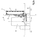
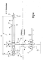
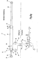
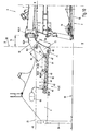
- FIG.1 and Fig.2 show an inventive side mower 2 mounted on a carrier vehicle 1 in a working position and the figures Figure 3 and Figure 4 show an inventive mower 2 mounted to a carrier vehicle 1 in a transport position.
- the side mower 2 consists essentially of a support structure 4, for example for connection to the three-point hydraulic system of a carrier vehicle 4, for example one. Tractor, and a boom 5, which connects the cutter bar 3 with the support structure 4 vertically movable.
- the cantilever arm 5 consists of two cantilever elements 6, 7, wherein the first cantilever element 6 is struck in a pivot joint 8 on the supporting structure 4 in a joint axis extending essentially in the direction of travel F.
- the second boom element 7 is struck in a rotary joint 10 on the first boom element 6 in a substantially upright but at the same time inclined also in the direction of travel F hinge axis 11.
- the second boom element 7 is struck at its free end in the region of the center suspension 18 in a pivot joint 12 on the portal frame 17 in a direction substantially in the direction of travel F axis of articulation.
- the portal frame 17 spans as part of the cutter bar 3, the gear housing 14 of Scheibenmähwerks with its mower discs 15, which are located in a known manner below a protective cover 16.
- the somähwerk 2 is located with respect to the direction of travel F right of the vertical longitudinal center plane 19 of the host vehicle 1, it being equally possible, the side mower 2 left of the vertical longitudinal center plane 19 of the host vehicle. 1 to arrange, and in principle it is also possible that on both sides of the longitudinal center plane 19 each a side mower is arranged.
- the carrier vehicle 1 or the mower 2 according to Fig.1 and Fig.2 an orthogonal coordinate system to be associated with the xyz coordinates whose z-axis is identical to the hinge axis 9 of the rotary joint 8, whose y-axis perpendicularly intersects the hinge axis 9 and whose x-axis is parallel to the horizontal footprint 20 of the host vehicle. It is further assumed that the hinge axis 9 is parallel to the horizontal footprint 20. By definition, the position of the coordinate origin should be located centrally in the pivot bearing of the rotary joint 8.
- the plane spanned by the xy-axis plane is a vertical transverse plane 21
- the plane spanned by the yz-axis a vertical longitudinal plane 22
- Fig.1 shows the carrier vehicle 1 with the side mower 2 in a plan view and Fig.2 seen in a side view from the rear with a view in driving and working direction F in working position.
- the cutter bar 3 In the working position, the cutter bar 3 is below the horizontal plane 23, while the boom 5 is above the horizontal plane 23, and thus in the 1st quadrant.
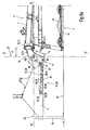
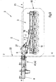
- the cantilever element 6 a cantilever lever 69, at which in the pivot point 25 a torque arm 27, spaced with the lever arm 56 from a first pivot 10 with a Joint axis 11 is struck.
- the lever 69 and the torque arm 27 lie in a plane approximately parallel to the horizontal plane 23rd
- the lever 69 is part of an orthogonal angle lever 24, which has a first pivot 8 with a first hinge axis 9.
- the hinge axes 9 and 11 in different planes, which include a spatial angle in the range of about 65 ° to 85, preferably about 75 ° to each other.
- the two axes of articulation 8, 11 are spaced apart from one another by the distance dimension 70, so that these axes 8, 11 run through vertical planes spaced apart from this distance dimension 70.
- these two vertical planes extend parallel to one another, which however is not absolutely necessary for realizing the invention, ie they can also assume a diverging course relative to one another.
- the hinge axis 9 of the rotary joint 8 is incorporated in a double lever 71, wherein above the hinge axis 9 as part of the double lever 71, the upper lever 72 extends rigidly connected to the second pivot 10 connects to the second hinge axis 11 with the second lever 69, and wherein below the hinge axis 9, the lower lever 73 extends as a second part of the double lever 71, on which the excavating cylinder 31 and the energy accumulator 40 is hingedly hinged.
- the other end of the torque arm 27 is struck in the hinge point 26 on the boom element 7 and is supported on this.
- the torque arm 27 is simultaneously equipped with an overload protection 28, which is triggered as a force limit in the event of collision of the cutter bar 3 with an obstacle, so that the cutter bar 3 against the driving and working direction F backwards pivots about the hinge axis 11 of the rotary joint 10 and can dodge. Due to an inclination angle of about 5 ° - 25 °, preferably 15 °, the forwardly tilted in the direction of travel hinge axis 11, the cutter bar 3 then pivots on the same side upwards, so that the cutter bar 3 also lifts off the ground.
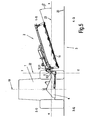
- Figure 4 show the cutter bar 3 in a transport position, wherein the cantilever arm 5 previously pivoted about the hinge axis 9 (coordinate origin) from the predominantly horizontal working position of the 1st quadrant 1-Q by the pivot angle ⁇ in the predominantly vertical position of the 2nd quadrant 2-Q is.
- Figure 5 shows a headland position in which the mower is pivoted within the 1st quadrant to the pivot angle ⁇ relative to the ground and thus lifted from this.
- the excavating cylinder 31 In the vertical transverse plane 21 (x-y plane), the excavating cylinder 31 is located as an actuator for the pivoting operation.
- the excavating cylinder 31 accommodates two working pistons 33, 35 with their piston rods 34, 36, which lie in an aligned axis 91, which is defined by the connecting straight line between the articulated and articulated points 29, 30.
- the excavating cylinder 31 is thus struck in hinge points 29, 30, wherein it is in the hinge point 29 on the support structure 4 and in the hinge point 30, spaced with a lever arm 55 to the hinge axis 9 of the rotary joint 8 at the boom element 6 and the angle lever 24 is supported.
- the excavating cylinder 31 is capable of applying an upward torque about the hinge axis 9 of the rotary joint 8 to the cutter bar 3 upon appropriate pressurization with a pressurized fluid, whereby it can perform an upward pivotal movement.
- the different switching positions of the controller are represented by the letters abcd, wherein the switch positions b and d can also be locked.
- the positions a and c are flow positions whose positions define the directions of movement of the piston rods 34, 36 determine.
- the position b is the so-called floating position, in which the piston rods 34, 36 can move freely under the action of external forces within the cylinder housing 32, since both pressure chambers 37, 38 are connected to the tank return line T and the pressure line P is locked.
- the position d is the blocking position in which all line connections P; T, A1, B1 are blocked.
- the excavating cylinder 31 takes in its cylinder housing 32 has two working pistons 33; 35, a first piston 33 with a first piston rod 34 and a second piston 35 with a second piston rod 36, in on.
- Inside the cylinder housing 32 are the two working pistons 33, 36 facing each other and between them is a common pressure chamber 38.
- Both piston rods 34, 36 extend oppositely from their associated Working piston 33, 35 averted and emerge from the respective cylinder head 75, 76 end of the cylinder housing 32 and terminate in joint eyes of the hinge points 29, 30th
- the piston rod chamber 80 is aerated or vented through the atmospheric and ambient air by the loading and final ventilators.
- the cutter bar 3 is located on the ground and he can adapt to the current ground profile by transom following the hinge axis 13 of the pivot joint 12 of the center suspension 18 accordingly.
- the boom 5 can move freely about the hinge axis 9 of the rotary joint 8, so that the cutter bar 3 can also adapt to different heights of the soil profile.
- both working pistons 33, 35 and their piston rods 34, 36 float axially freely within the cylinder housing 32, whereby a non-constraining ground adaptation of the cutter bar can take place, which is symbolized by the double arrow 79.
- the distance measure 82 can thus within the limits provided by the mechanical feedback of the musculoskeletal system, the boom 5 and the cutter bar 3, momentarily on the variable situation of the oscillating pivotal movements of the cutter bar 3 about the pivot axis 13 of the pivot joint 12 zwteilungs arthritis to adjust.
- the initial position of the piston rod 34 is characterized in that it fully retracted on the stop 77 of the cylinder head 76 is applied.
- FIG 8D shows the circuit diagram in the valve position c, so that now the hydrostatic pressure of the pump line P at the valve outlet A1 and thus on the wiring harness 81 and the pressure chamber 38 is applied. Due to the hydrostatic pressure in the pressure chamber 38, the working pistons 33, 35 are displaced relative to each other in such a way that the piston distance 74 or the distance 83 of the pivot points 29, 30 increases in the direction of the movement arrow 89.
- the pressurized fluid in the pressure chamber 37 can flow back via the orifice 88 of the throttle check valve 87 via the connecting line 82 to the tank.
- the cutter bar 3 is thus lifted off the ground. and eg in the headland position according to Fig. 5 , or in the transport position according to Figure 3 , or raised in any intermediate position between the working or transport position.
- Fig.8e shows the circuit diagram in the valve position d and thus in the locked position of the control unit 68.
- This locking position can be used in principle in any position of the raised cutter bar 3 to lock the cutter bar 3 in the respective position hydraulically.
- both piston rods 34, 36 are extended into their respective end position and bear against the cylinder heads 75, 76 on the inside of the cylinder housing 32, i.e. on the cylinder heads 75, 76. the piston distance 74 and the distance measure 83 have reached their maximum.
- Fig.8g shows the circuit diagram in the valve position a in the driven starting position at the beginning of the lowering process of the cutter bar 3 from the transport position.
- the hydrostatic pressure of the pressure line P is applied to the connecting line 82 and thus to the pressure chamber 37, and the pressure chamber 38 is connected to the connecting line 81 to the tank return line T.
- the hydrostatic pressure only the working piston 33 with the piston rod 34 can initially move in the direction of the working piston 35, so that the piston distance 74 and the distance dimension 83 are shortened. This causes the cutter bar 3 to initiate a downward pivotal movement, which would then end when the stroke of the power piston 33 is consumed.
- the maximum stroke 84 of the working piston 33 is dimensioned so that the state of the indifferent balance of the cutter bar 3 is overcome during downward pivoting and thus the force of gravity of the cutter bar now as a driving force a torque for downward movement of the cutter bar 3 and the boom 5 exerts.
- This state that gravity is effective as a driving force is, for example, as in Fig. 3a already reached when the cutter bar 3 has moved back from the 2-quadrant into the 1-quadrant 1.-Q.
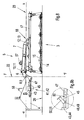
- the Fig. 6 and Figure 7 show a mowing situation on a slope, the Fig. 6 a downwardly inclined and the Figure 7 showing an upward sloping embankment.
- the excavating cylinder 31 is protected in the interior of the support structure 4 from external unwanted force and pollution influences accommodated. This also allows optimum ground clearance H between the support structure and ground contact surface 20th
- the energy accumulator 41 is designed as a hydraulic cylinder 42 with a working piston 44 and a Kobenstange 45 which is acted upon in the piston bottom side pressure chamber 46 with the pressure of a prestressed hydropneumatic pressure accumulator 93.
- the piston rod 45 is inserted with its extended free end in a surrounding them with play affected shaft tube 47, so that they can move freely in this shaft tube 47 axially displaceable.
- the end of the shaft tube is a joint eye, which is connected at the pivot point 40 with the boom element 6.
- the cylinder housing 43 of the hydraulic cylinder 42 at the same time includes a receiving bore for a stop pin, so that it can be picked up by this, which is the case in the hinge point 39.
- the pivot point 39 is struck against the supporting structure 4, so that the force accumulator 41 or the hydraulic cylinder 42 is also supported on the supporting structure 4 at the same time.
- the piston rod 45 is provided outside the cylinder housing 43 with a transverse bore 48 which is penetrated by a hinge pin 49 which receives a pivotable cap valve 50.
- the distance of the transverse bore 48 from the free end face formed as an annular surface end of the shaft tube 47 is dimensioned so that acts on the piston rod 45 tight-fitting cap flap 50 as a compressive force transmitted force transmission element 51 between the piston rod 45 and shaft tube 47.
- this power transmission element 51 is supported on the one hand on the hinge pin 49 in the transverse bore 48 of the piston rod 45 at this and the other on the annular surface of the shaft tube 47 from.
- the energy accumulator 41 is thus clamped between the hinge points 39 and 40.
- the pivot point 40 is spaced with a lever arm to the hinge axis 9 of the rotary joint 8, so that the effective force in the energy storage 41 via the piston rod 45 can exert on this an upward torque, which tends to lift the cutter bar 3 from the ground, the Torque in its amount is such that it comes only to a bottom pressure relief.
- the size of the preset force or the torque can be set in a known manner by different strong compression of the accumulator bladder of the hydropneumatic accumulator with the hydraulic system of the carrier vehicle.
- a measure of the soil pressure relief is impressed on the reservoir bladder hydraulic biasing pressure, which can be read in a known manner by means of a pressure gauge.
- FIG. 2b shows detail B Fig.2 in an enlarged view with inserted cap flap 50, so that the energy storage device 41 is effective for the bottom contact pressure relief
- the cap flap 50 is connected to a pull rope, which is guided into the driver's cab, and it can be unlocked from the driver's seat and thereby. be put out of action by being so folded around the axis of the hinge pin 49 of the clamp rod 45.
- 8B shows this situation using detail B.
- Figure 8 in an enlarged view, but with raised flap. This serves to make ineffective the ground pressure relief before disconnecting the mower 2 from the carrier vehicle 1 to make the support structure 4 against the angle lever forces.
- the support structure 4 relative to the hinge axis 9 of the rotary joint 8, which results from the energy storage, set torque-free This can be done without the driver having to leave his tractor seat; or without first the hydraulic pressure from the pressure chamber of the accumulator must be drained.
- this not only serves the comfort of the driver but also equally for reducing a risk of injury to the driver when disconnecting the mower when decoupling the hydraulic supply line.
- this includes the advantage that the pressure state in the energy storage 41 is maintained even during the decoupled phase of the carrier vehicle 1, so that the rejoining of the hydraulic connection to the on-board hydraulics for re-compressing and biasing the storage bubble of hydropneumatic accumulator 93 is omitted after re-coupling of the mower 2 to the carrier vehicle 1 and also the set unloading force is stored.
- this advantage of the invention eliminates the otherwise required for each coupling process pressure charging of the pressure chamber of the energy accumulator 41, so that these hydraulic connection neither when coupling nor during uncoupling must be made every time again.
- Figure 10 shows a section Figure 8a in the parking position with inoperative power transmission element 51 by the cap valve 50 is spent in a remote from the piston rod 45 position.
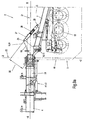
- Figure 11 shows an enlarged section of the transport position of the cutter bar 3 from Fig. 3 , It shows in particular on an enlarged scale the support structure 4, the pivoted angle lever 24, the excavating cylinder 31 with extended piston rod 36, the hydropneumatically prestressed energy storage 41, designed as a hydraulic cylinder 42 with its extended piston rod 45 and the force-free folded down power transmission element 51, the pneumatically prestressed pressure accumulator 93rd , and the shaft tube 47, from which the piston rod 45 has largely moved out. Due to the pivotal movement of the angle lever 24 by the pivot angle ⁇ , the distance between the hinge points 39 and 40 has increased significantly, so that the force transmission element 51 has moved away from the end face 94 of the shaft tube 47.
- the power transmission element 51 has become free of force and in this state, it can easily and with minimum effort of the Piston rod 45 can be folded up by cable pull from the driver's seat into a piston rod far away position.
- This folded-up position of the power transmission element 51 is in Figure 10 shown.
- the piston 44 and the piston rod 45 of the prestressed hydraulic cylinder 42 of the force accumulator 41 moves freely out of the cylinder housing 43 as a result of the accumulator 93 impressed and clamped in this pneumatic pressure of the accumulator, but remains partially in which of the cylinder housing 43 further away shaft tube 47, so that the reception and guidance of the piston rod 45 is maintained by the shaft tube 47.
- the piston 44 is supported in this end position situation of the piston rod 45 with its piston ring surface inside on the cylinder head of the cylinder housing 43, so that thus the piston rod 45 has reached its extended end position, the energy storage device 41 remains biased.
- the power transmission element 51 designed as a cap flap 50 remains folded up, ie in its non-functional position.
- the piston rod 45 now pushes back into the shaft tube 47 without force and while the force transmission element 51 or the cap flap 50 is held up by the cable pull, ie is held in its non-functional position.
- the boom element 7 extends from the pivot 10 backwards against the direction of travel F by an angle s with respect to the vertical transverse plane 21 to the center suspension 18 to the rear, which also has a favorable precondition for the support and the available lever arm 56 of the torque arm 27 creates.
- the angle ⁇ is approximately in the range of 5 ° to 25 °, preferably about 15 °.
- the second boom element with a first support element 57 and the support structure 4 equipped with a complementary support member 58 are designed such that they engage with one another in a form-fitting manner.
- Exemplary of such a positive mating of first and complementary support elements are, for example, pairings such as ball / ball socket, pin / sleeve or pyramid roof / pyramid trough. It is essential to the invention that this pairing of support elements is capable of not only absorbing vertical forces but equally of absorbing horizontal forces resulting from acceleration processes.
- the mower has a display device for the correct altitude of the support structure 4, which can be viewed from the driver's seat.
- the supporting structure should occupy a defined height H with respect to the contact surface 20 of the floor, which can be adjusted with the hydraulic lifting mechanism of the carrier vehicle.
- the orientation angle ⁇ serves as an indirect measure of the height H of the supporting structure.
- the pendulum movement limiting device 59 is equipped with a height adjustment mark 60. This is the detail A in Figure 7 respectively. Fig. 7a refer to.
- the pendulum motion limiting device 59 is on the one hand a part of the boom element 7 of the extension arm 5 and on the other part of the portal frame 17.
- the pendulum motion limiting device 59 consists essentially of a tab 64 which is connected in a hinge connection 62 with the portal frame 17, and at the same time through a slot as a breakthrough of the fork piece 63 passes up through this protrudes. At the upper end of the tab, this has a stopper thickening 65 with a mark in the form of a notch.
- aannaneinstellmarke 60 is fixedly mounted in the form of an arrow.
- the boom element 6 is thus functionally configured as an orthogonal angle lever 24, which is defined by the fact that this two spatially at an angle to each other pivot joints 8,10 are associated with the pivot axes 9,11, and being at the same time the torque arm 27 with the Overload protection 28 is supported.
- the actuating element lifting cylinder 31 and the bottom pressure relief hydraulic cylinder 42 are articulated as an energy storage 41, whereby the angle lever thus exposed to the support structure 4 in different operating situations different load situations, can support the angle lever 24 also assumes the function of a connecting element between the Supporting structure 4 and the second boom element 7 of the
- the design of the angle lever 24 in its multi-functionality is therefore a key inventive importance in terms of its simple and therefore cost-effective design because of its self-consolidating multi-dimensional functionality, because of the improvement in reliability in the event of collision of the mower with an obstacle, and because of the increase in comfort and safety when connecting and disconnecting the mower 1 for the operator or driver of the host vehicle to.
- the invention is illustrated and explained by way of example on a disc mower and it can equally be applied to drum mowers.
Claims (11)
- Faucheuse, en particulier faucheuse latérale destinée à être montée sur un dispositif de levage d'un véhicule porteur agricole, comprenant un dispositif de fauchage qui est guidé sur le côté du véhicule porteur agricole, dans une position de travail et de service, et qui comporte un certain nombre d'organes de coupe recevant des lames de coupe tournant autour d'un axe vertical; comprenant un dispositif de support et de guidage en tant qu'élément de liaison entre la faucheuse et le véhicule porteur, avec un bras pivotant pour faire basculer le dispositif de fauchage d'une position de travail et de service sensiblement horizontale dans une position relevée de manoeuvre et/ou de transport; et comprenant un organe d'actionnement pour faire pivoter le dispositif de fauchage d'une position de travail proche du sol dans une position de manoeuvre ou de transport relevée, éloignée du sol, caractérisée par le fait que le dispositif de support et de guidage comprend un organe d'actionnement sous forme de vérin de levage (3 1) à fluide sous pression, qui présente deux pistons de travail (33; 35) indépendants l'un de l'autre, qui enferment entre eux une chambre de pression (38) commune.
- Faucheuse selon la revendication 1, caractérisée par le fait que les pistons de travail (33; 35) se situent sur un axe (91) aligné avec la droite de liaison entre les points d'articulation (29, 30).
- Faucheuse selon les revendications 1 et 2, caractérisée par le fait que l'un des deux pistons de travail (33; 35) peut être soumis à une pression à double effet et l'autre piston de travail (33 ou 35) à une pression à simple effet.
- Faucheuse selon les revendications 1 à 3, caractérisée par le fait que les deux pistons de travail (33; 35) sont logés dans un corps de cylindre.
- Faucheuse selon les revendications 1 à 4, caractérisée par le fait que lors du mouvement pivotant dirigé vers le haut de la barre de coupe (3), le vérin de levage (31) travaille comme vérin de pression.
- Faucheuse selon les revendications 1 à 5, caractérisée par le fait que pendant le mouvement pivotant dirigé vers le haut de la barre de coupe (3), la chambre de pression (38) commune des deux pistons de travail (33; 35) du vérin de levage (31) est reliée à la conduite de pression (P), de manière à être soumise à une pression.
- Faucheuse selon les revendications 1 à 4, caractérisée par le fait que lors de la phase dirigée vers le bas de l'opération d'abaissement de la barre de coupe (3), la chambre de pression (37) côté tige de piston est soumise à une pression hydrostatique et la chambre de pression (38) commune des deux pistons de travail (33; 35) est reliée à la conduite de réservoir (T).
- Faucheuse selon les revendications 1 à 7, caractérisée par le fait que l'appareil de commande (68) et le vérin de levage (31) sont reliés entre eux par deux conduites de liaison (81, 82).
- Faucheuse selon les revendications 1 à 8, caractérisée par le fait qu'au moins un obturateur d'étranglement (86; 88) est associé à chaque conduite de liaison (81, 82).
- Faucheuse selon les revendications 1 à 9, caractérisée par le fait qu'un clapet antiretour avec étranglement (85; 87) est associé à chaque conduite de liaison (81, 82).
- Faucheuse selon les revendications 1 à 10, caractérisée par le fait que le vérin de levage (31) hydraulique peut être commandé par un seul appareil de commande (68) à double action.
Applications Claiming Priority (1)
| Application Number | Priority Date | Filing Date | Title |
|---|---|---|---|
| DE102005061976A DE102005061976A1 (de) | 2005-12-23 | 2005-12-23 | Mähmaschine |
Publications (3)
| Publication Number | Publication Date |
|---|---|
| EP1800529A1 EP1800529A1 (fr) | 2007-06-27 |
| EP1800529B1 true EP1800529B1 (fr) | 2008-11-12 |
| EP1800529B2 EP1800529B2 (fr) | 2012-05-30 |
Family
ID=37882245
Family Applications (1)
| Application Number | Title | Priority Date | Filing Date |
|---|---|---|---|
| EP06025318A Active EP1800529B2 (fr) | 2005-12-23 | 2006-12-07 | Faucheuse |
Country Status (4)
| Country | Link |
|---|---|
| EP (1) | EP1800529B2 (fr) |
| AT (1) | ATE413800T1 (fr) |
| DE (3) | DE202005021551U1 (fr) |
| DK (1) | DK1800529T4 (fr) |
Cited By (1)
| Publication number | Priority date | Publication date | Assignee | Title |
|---|---|---|---|---|
| EP2174538A1 (fr) | 2008-10-08 | 2010-04-14 | Claas Saulgau Gmbh | Appareil de travail, notamment pour l'agencement sur la face arrière ou avant d'un véhicule agricole |
Families Citing this family (6)
| Publication number | Priority date | Publication date | Assignee | Title |
|---|---|---|---|---|
| DE202007014320U1 (de) | 2007-10-12 | 2007-12-06 | Fella-Werke Gmbh & Co. Kg | Trag- und Führungseinrichtung für eine Landmaschine |
| SI3329760T1 (sl) * | 2013-12-23 | 2021-08-31 | Kverneland Group Kerteminde A/S | Kmetijski stroj |
| DE102014104379A1 (de) | 2014-03-28 | 2015-10-01 | Claas Saulgau Gmbh | Arbeitsgerät zum Ankuppeln an eine landwirtschaftliche Arbeitsmaschine |
| FR3037211B1 (fr) * | 2015-06-15 | 2018-01-19 | Kuhn Sa | Machine agricole portee avec un groupe d'outils pouvant etre deporte lateralement |
| DE202016002490U1 (de) * | 2016-04-18 | 2016-05-25 | Maschinenfabrik Bernard Krone GmbH & Co. KG | Landwirtschaftliche Arbeitsmaschine mit verbesserter Transportsicherung |
| IT201700010720A1 (it) | 2017-02-01 | 2018-08-01 | Roc S R L | Macchina agricola |
Family Cites Families (6)
| Publication number | Priority date | Publication date | Assignee | Title |
|---|---|---|---|---|
| FR2160378A1 (fr) † | 1972-09-27 | 1973-06-29 | Poclain Sa | |
| NL7604451A (nl) † | 1976-04-27 | 1977-10-31 | Texas Industries Inc | Maaimachine. |
| DE19534695C2 (de) † | 1995-09-19 | 1998-12-24 | Hans Grenzebach | An einem Schlepper ansetzbares Heckmähwerk |
| FR2794934B1 (fr) † | 1999-06-17 | 2001-08-10 | Kuhn Sa | Machine agricole du type faucheuse ou faucheuse- conditionnneuse comportant un organe d'amortissement |
| DE10011730C2 (de) † | 2000-03-10 | 2002-01-31 | Krone Bernhard Gmbh Maschf | Mähmaschine |
| DE50200957D1 (de) † | 2002-04-05 | 2004-10-14 | Festo Ag & Co | Fluidbetätigte Antriebsvorrichtung |
-
2005
- 2005-12-23 DE DE202005021551U patent/DE202005021551U1/de not_active Expired - Lifetime
- 2005-12-23 DE DE102005061976A patent/DE102005061976A1/de not_active Ceased
-
2006
- 2006-12-07 EP EP06025318A patent/EP1800529B2/fr active Active
- 2006-12-07 DE DE502006002057T patent/DE502006002057D1/de active Active
- 2006-12-07 DK DK06025318.4T patent/DK1800529T4/da active
- 2006-12-07 AT AT06025318T patent/ATE413800T1/de active
Cited By (2)
| Publication number | Priority date | Publication date | Assignee | Title |
|---|---|---|---|---|
| EP2174538A1 (fr) | 2008-10-08 | 2010-04-14 | Claas Saulgau Gmbh | Appareil de travail, notamment pour l'agencement sur la face arrière ou avant d'un véhicule agricole |
| DE102009023956A1 (de) | 2008-10-08 | 2010-04-15 | Claas Saulgau Gmbh | Arbeitsgerät, insbesondere zur heckseitigen oder frontseitigen Anordnung an einem landwirtschaftlichen Fahrzeug |
Also Published As
| Publication number | Publication date |
|---|---|
| DE202005021551U1 (de) | 2008-11-27 |
| EP1800529B2 (fr) | 2012-05-30 |
| DK1800529T4 (da) | 2012-09-10 |
| DK1800529T3 (da) | 2009-03-16 |
| ATE413800T1 (de) | 2008-11-15 |
| DE102005061976A1 (de) | 2007-07-12 |
| EP1800529A1 (fr) | 2007-06-27 |
| DE502006002057D1 (de) | 2008-12-24 |
Similar Documents
| Publication | Publication Date | Title |
|---|---|---|
| EP1800529B1 (fr) | Faucheuse | |
| EP2042011B1 (fr) | Véhicule de chantier avec dispositif de montage | |
| EP0182091B1 (fr) | Elévateur de puissance pour un dispositif de levage | |
| EP1438886B1 (fr) | Dispositif d'accouplement | |
| EP1348324B1 (fr) | Faucheuse à barres de coupe couplées et articulées | |
| EP2186713B1 (fr) | Dispositif de ballastage et véhicule agricole équipé avec ce dernier | |
| US20110298197A1 (en) | Adjustable and Foldable V-Shaped Hay Rake | |
| EP3075246B1 (fr) | Machine agricole et procede de securite | |
| EP1205097B1 (fr) | Unité autonivelleuse de timon et bout en chape | |
| EP1514463A1 (fr) | Dispositif pour attacher un outil à un véhicule | |
| EP1800528B1 (fr) | Faucheuse | |
| EP2042410B1 (fr) | Véhicule agricole | |
| EP1800530B1 (fr) | Faucheuse | |
| DE19953380A1 (de) | Selbstfahrende Mäheinheit | |
| DE3030417C2 (de) | Ausklinkvorrichtung | |
| DE3448426C3 (de) | Landwirtschaftliche Maschine | |
| DE3444412C2 (fr) | ||
| AT502053B1 (de) | Anbauvorrichtung für eine landmaschine | |
| EP0903076B1 (fr) | Protecteur de collision pour appareil de travail agricole tracté | |
| DE102009029037A1 (de) | Forstanhänger mit Knickdeichsel | |
| DE2614517C3 (de) | Sperrvorrichtung für die Hubwelle eines hydraulischen Krafthebers von landwirtschaftlich nutzbaren Schleppern mit Dreipunktaufhängung | |
| EP1040751A2 (fr) | Faucheuse automotrice | |
| DE1557673C (de) | Aushebehilfsvornchtung fur über die Dreipunkt Geratekupplung von Schlep pern aushebbare Arbeitsgeräte, insbeson dere Bodenbearbeitungsgeräte | |
| DE19960659A1 (de) | Überlastsicherung als Auffahrschutz für Frontmähwerke | |
| DE102019135685A1 (de) | Anhänger, insbesondere Forstwirtschaftlicher Anhänger |
Legal Events
| Date | Code | Title | Description |
|---|---|---|---|
| PUAI | Public reference made under article 153(3) epc to a published international application that has entered the european phase |
Free format text: ORIGINAL CODE: 0009012 |
|
| AK | Designated contracting states |
Kind code of ref document: A1 Designated state(s): AT BE BG CH CY CZ DE DK EE ES FI FR GB GR HU IE IS IT LI LT LU LV MC NL PL PT RO SE SI SK TR |
|
| AX | Request for extension of the european patent |
Extension state: AL BA HR MK YU |
|
| 17P | Request for examination filed |
Effective date: 20071227 |
|
| AKX | Designation fees paid |
Designated state(s): AT BE BG CH CY CZ DE DK EE ES FI FR GB GR HU IE IS IT LI LT LU LV MC NL PL PT RO SE SI SK TR |
|
| GRAP | Despatch of communication of intention to grant a patent |
Free format text: ORIGINAL CODE: EPIDOSNIGR1 |
|
| GRAS | Grant fee paid |
Free format text: ORIGINAL CODE: EPIDOSNIGR3 |
|
| GRAA | (expected) grant |
Free format text: ORIGINAL CODE: 0009210 |
|
| AK | Designated contracting states |
Kind code of ref document: B1 Designated state(s): AT BE BG CH CY CZ DE DK EE ES FI FR GB GR HU IE IS IT LI LT LU LV MC NL PL PT RO SE SI SK TR |
|
| REG | Reference to a national code |
Ref country code: GB Ref legal event code: FG4D Free format text: NOT ENGLISH |
|
| REG | Reference to a national code |
Ref country code: CH Ref legal event code: EP |
|
| REG | Reference to a national code |
Ref country code: IE Ref legal event code: FG4D Free format text: LANGUAGE OF EP DOCUMENT: GERMAN |
|
| REF | Corresponds to: |
Ref document number: 502006002057 Country of ref document: DE Date of ref document: 20081224 Kind code of ref document: P |
|
| REG | Reference to a national code |
Ref country code: DK Ref legal event code: T3 |
|
| LTIE | Lt: invalidation of european patent or patent extension |
Effective date: 20081112 |
|
| PG25 | Lapsed in a contracting state [announced via postgrant information from national office to epo] |
Ref country code: LT Free format text: LAPSE BECAUSE OF FAILURE TO SUBMIT A TRANSLATION OF THE DESCRIPTION OR TO PAY THE FEE WITHIN THE PRESCRIBED TIME-LIMIT Effective date: 20081112 Ref country code: ES Free format text: LAPSE BECAUSE OF FAILURE TO SUBMIT A TRANSLATION OF THE DESCRIPTION OR TO PAY THE FEE WITHIN THE PRESCRIBED TIME-LIMIT Effective date: 20090223 |
|
| PG25 | Lapsed in a contracting state [announced via postgrant information from national office to epo] |
Ref country code: SI Free format text: LAPSE BECAUSE OF FAILURE TO SUBMIT A TRANSLATION OF THE DESCRIPTION OR TO PAY THE FEE WITHIN THE PRESCRIBED TIME-LIMIT Effective date: 20081112 Ref country code: PL Free format text: LAPSE BECAUSE OF FAILURE TO SUBMIT A TRANSLATION OF THE DESCRIPTION OR TO PAY THE FEE WITHIN THE PRESCRIBED TIME-LIMIT Effective date: 20081112 Ref country code: IS Free format text: LAPSE BECAUSE OF FAILURE TO SUBMIT A TRANSLATION OF THE DESCRIPTION OR TO PAY THE FEE WITHIN THE PRESCRIBED TIME-LIMIT Effective date: 20090312 Ref country code: FI Free format text: LAPSE BECAUSE OF FAILURE TO SUBMIT A TRANSLATION OF THE DESCRIPTION OR TO PAY THE FEE WITHIN THE PRESCRIBED TIME-LIMIT Effective date: 20081112 Ref country code: LV Free format text: LAPSE BECAUSE OF FAILURE TO SUBMIT A TRANSLATION OF THE DESCRIPTION OR TO PAY THE FEE WITHIN THE PRESCRIBED TIME-LIMIT Effective date: 20081112 |
|
| BERE | Be: lapsed |
Owner name: CLAAS SAULGAU G.M.B.H. Effective date: 20081231 |
|
| REG | Reference to a national code |
Ref country code: IE Ref legal event code: FD4D |
|
| PG25 | Lapsed in a contracting state [announced via postgrant information from national office to epo] |
Ref country code: EE Free format text: LAPSE BECAUSE OF FAILURE TO SUBMIT A TRANSLATION OF THE DESCRIPTION OR TO PAY THE FEE WITHIN THE PRESCRIBED TIME-LIMIT Effective date: 20081112 Ref country code: IE Free format text: LAPSE BECAUSE OF FAILURE TO SUBMIT A TRANSLATION OF THE DESCRIPTION OR TO PAY THE FEE WITHIN THE PRESCRIBED TIME-LIMIT Effective date: 20081112 Ref country code: BG Free format text: LAPSE BECAUSE OF FAILURE TO SUBMIT A TRANSLATION OF THE DESCRIPTION OR TO PAY THE FEE WITHIN THE PRESCRIBED TIME-LIMIT Effective date: 20090212 Ref country code: RO Free format text: LAPSE BECAUSE OF FAILURE TO SUBMIT A TRANSLATION OF THE DESCRIPTION OR TO PAY THE FEE WITHIN THE PRESCRIBED TIME-LIMIT Effective date: 20081112 Ref country code: MC Free format text: LAPSE BECAUSE OF NON-PAYMENT OF DUE FEES Effective date: 20081231 |
|
| PLBI | Opposition filed |
Free format text: ORIGINAL CODE: 0009260 |
|
| PG25 | Lapsed in a contracting state [announced via postgrant information from national office to epo] |
Ref country code: SE Free format text: LAPSE BECAUSE OF FAILURE TO SUBMIT A TRANSLATION OF THE DESCRIPTION OR TO PAY THE FEE WITHIN THE PRESCRIBED TIME-LIMIT Effective date: 20090212 Ref country code: PT Free format text: LAPSE BECAUSE OF FAILURE TO SUBMIT A TRANSLATION OF THE DESCRIPTION OR TO PAY THE FEE WITHIN THE PRESCRIBED TIME-LIMIT Effective date: 20090413 Ref country code: CZ Free format text: LAPSE BECAUSE OF FAILURE TO SUBMIT A TRANSLATION OF THE DESCRIPTION OR TO PAY THE FEE WITHIN THE PRESCRIBED TIME-LIMIT Effective date: 20081112 |
|
| 26 | Opposition filed |
Opponent name: OCTROOIBUREAU VAN DER LELY N.V. Effective date: 20090807 |
|
| PLAX | Notice of opposition and request to file observation + time limit sent |
Free format text: ORIGINAL CODE: EPIDOSNOBS2 |
|
| PG25 | Lapsed in a contracting state [announced via postgrant information from national office to epo] |
Ref country code: SK Free format text: LAPSE BECAUSE OF FAILURE TO SUBMIT A TRANSLATION OF THE DESCRIPTION OR TO PAY THE FEE WITHIN THE PRESCRIBED TIME-LIMIT Effective date: 20081112 Ref country code: BE Free format text: LAPSE BECAUSE OF NON-PAYMENT OF DUE FEES Effective date: 20081231 |
|
| NLR1 | Nl: opposition has been filed with the epo |
Opponent name: OCTROOIBUREAU VAN DER LELY N.V. |
|
| PLBB | Reply of patent proprietor to notice(s) of opposition received |
Free format text: ORIGINAL CODE: EPIDOSNOBS3 |
|
| PG25 | Lapsed in a contracting state [announced via postgrant information from national office to epo] |
Ref country code: LU Free format text: LAPSE BECAUSE OF NON-PAYMENT OF DUE FEES Effective date: 20081207 Ref country code: HU Free format text: LAPSE BECAUSE OF FAILURE TO SUBMIT A TRANSLATION OF THE DESCRIPTION OR TO PAY THE FEE WITHIN THE PRESCRIBED TIME-LIMIT Effective date: 20090513 Ref country code: CY Free format text: LAPSE BECAUSE OF FAILURE TO SUBMIT A TRANSLATION OF THE DESCRIPTION OR TO PAY THE FEE WITHIN THE PRESCRIBED TIME-LIMIT Effective date: 20081112 |
|
| PG25 | Lapsed in a contracting state [announced via postgrant information from national office to epo] |
Ref country code: TR Free format text: LAPSE BECAUSE OF FAILURE TO SUBMIT A TRANSLATION OF THE DESCRIPTION OR TO PAY THE FEE WITHIN THE PRESCRIBED TIME-LIMIT Effective date: 20081112 |
|
| PG25 | Lapsed in a contracting state [announced via postgrant information from national office to epo] |
Ref country code: GR Free format text: LAPSE BECAUSE OF FAILURE TO SUBMIT A TRANSLATION OF THE DESCRIPTION OR TO PAY THE FEE WITHIN THE PRESCRIBED TIME-LIMIT Effective date: 20090213 |
|
| PG25 | Lapsed in a contracting state [announced via postgrant information from national office to epo] |
Ref country code: IT Free format text: LAPSE BECAUSE OF FAILURE TO SUBMIT A TRANSLATION OF THE DESCRIPTION OR TO PAY THE FEE WITHIN THE PRESCRIBED TIME-LIMIT Effective date: 20081112 |
|
| REG | Reference to a national code |
Ref country code: CH Ref legal event code: PL |
|
| GBPC | Gb: european patent ceased through non-payment of renewal fee |
Effective date: 20101207 |
|
| PG25 | Lapsed in a contracting state [announced via postgrant information from national office to epo] |
Ref country code: CH Free format text: LAPSE BECAUSE OF NON-PAYMENT OF DUE FEES Effective date: 20101231 Ref country code: LI Free format text: LAPSE BECAUSE OF NON-PAYMENT OF DUE FEES Effective date: 20101231 |
|
| PG25 | Lapsed in a contracting state [announced via postgrant information from national office to epo] |
Ref country code: GB Free format text: LAPSE BECAUSE OF NON-PAYMENT OF DUE FEES Effective date: 20101207 |
|
| PUAH | Patent maintained in amended form |
Free format text: ORIGINAL CODE: 0009272 |
|
| STAA | Information on the status of an ep patent application or granted ep patent |
Free format text: STATUS: PATENT MAINTAINED AS AMENDED |
|
| 27A | Patent maintained in amended form |
Effective date: 20120530 |
|
| AK | Designated contracting states |
Kind code of ref document: B2 Designated state(s): AT BE BG CH CY CZ DE DK EE ES FI FR GB GR HU IE IS IT LI LT LU LV MC NL PL PT RO SE SI SK TR |
|
| REG | Reference to a national code |
Ref country code: DE Ref legal event code: R102 Ref document number: 502006002057 Country of ref document: DE Effective date: 20120530 |
|
| REG | Reference to a national code |
Ref country code: NL Ref legal event code: T3 |
|
| REG | Reference to a national code |
Ref country code: DK Ref legal event code: T4 |
|
| PG25 | Lapsed in a contracting state [announced via postgrant information from national office to epo] |
Ref country code: LV Free format text: LAPSE BECAUSE OF FAILURE TO SUBMIT A TRANSLATION OF THE DESCRIPTION OR TO PAY THE FEE WITHIN THE PRESCRIBED TIME-LIMIT Effective date: 20120530 |
|
| REG | Reference to a national code |
Ref country code: FR Ref legal event code: PLFP Year of fee payment: 10 |
|
| REG | Reference to a national code |
Ref country code: FR Ref legal event code: PLFP Year of fee payment: 11 |
|
| REG | Reference to a national code |
Ref country code: FR Ref legal event code: PLFP Year of fee payment: 12 |
|
| PGFP | Annual fee paid to national office [announced via postgrant information from national office to epo] |
Ref country code: NL Payment date: 20211221 Year of fee payment: 16 |
|
| REG | Reference to a national code |
Ref country code: NL Ref legal event code: MM Effective date: 20230101 |
|
| PG25 | Lapsed in a contracting state [announced via postgrant information from national office to epo] |
Ref country code: NL Free format text: LAPSE BECAUSE OF NON-PAYMENT OF DUE FEES Effective date: 20230101 |
|
| PGFP | Annual fee paid to national office [announced via postgrant information from national office to epo] |
Ref country code: FR Payment date: 20231221 Year of fee payment: 18 Ref country code: DK Payment date: 20231227 Year of fee payment: 18 Ref country code: DE Payment date: 20231214 Year of fee payment: 18 Ref country code: AT Payment date: 20231221 Year of fee payment: 18 |