EP1798797A1 - Vorrichtung für Stromversorgung und Verfahren für netzangeschlossene Brennstoffzellenvorrichtung - Google Patents
Vorrichtung für Stromversorgung und Verfahren für netzangeschlossene Brennstoffzellenvorrichtung Download PDFInfo
- Publication number
- EP1798797A1 EP1798797A1 EP06025730A EP06025730A EP1798797A1 EP 1798797 A1 EP1798797 A1 EP 1798797A1 EP 06025730 A EP06025730 A EP 06025730A EP 06025730 A EP06025730 A EP 06025730A EP 1798797 A1 EP1798797 A1 EP 1798797A1
- Authority
- EP
- European Patent Office
- Prior art keywords
- fuel cell
- output current
- power supply
- operating point
- supply control
- Prior art date
- Legal status (The legal status is an assumption and is not a legal conclusion. Google has not performed a legal analysis and makes no representation as to the accuracy of the status listed.)
- Withdrawn
Links
Images


Classifications
-
- H—ELECTRICITY
- H01—ELECTRIC ELEMENTS
- H01M—PROCESSES OR MEANS, e.g. BATTERIES, FOR THE DIRECT CONVERSION OF CHEMICAL ENERGY INTO ELECTRICAL ENERGY
- H01M8/00—Fuel cells; Manufacture thereof
- H01M8/04—Auxiliary arrangements, e.g. for control of pressure or for circulation of fluids
- H01M8/04082—Arrangements for control of reactant parameters, e.g. pressure or concentration
- H01M8/04089—Arrangements for control of reactant parameters, e.g. pressure or concentration of gaseous reactants
-
- H—ELECTRICITY
- H01—ELECTRIC ELEMENTS
- H01M—PROCESSES OR MEANS, e.g. BATTERIES, FOR THE DIRECT CONVERSION OF CHEMICAL ENERGY INTO ELECTRICAL ENERGY
- H01M8/00—Fuel cells; Manufacture thereof
- H01M8/04—Auxiliary arrangements, e.g. for control of pressure or for circulation of fluids
- H01M8/04298—Processes for controlling fuel cells or fuel cell systems
- H01M8/04313—Processes for controlling fuel cells or fuel cell systems characterised by the detection or assessment of variables; characterised by the detection or assessment of failure or abnormal function
- H01M8/04537—Electric variables
- H01M8/04544—Voltage
- H01M8/04559—Voltage of fuel cell stacks
-
- H—ELECTRICITY
- H01—ELECTRIC ELEMENTS
- H01M—PROCESSES OR MEANS, e.g. BATTERIES, FOR THE DIRECT CONVERSION OF CHEMICAL ENERGY INTO ELECTRICAL ENERGY
- H01M8/00—Fuel cells; Manufacture thereof
- H01M8/04—Auxiliary arrangements, e.g. for control of pressure or for circulation of fluids
- H01M8/04298—Processes for controlling fuel cells or fuel cell systems
- H01M8/04313—Processes for controlling fuel cells or fuel cell systems characterised by the detection or assessment of variables; characterised by the detection or assessment of failure or abnormal function
- H01M8/04537—Electric variables
- H01M8/04574—Current
- H01M8/04589—Current of fuel cell stacks
-
- H—ELECTRICITY
- H01—ELECTRIC ELEMENTS
- H01M—PROCESSES OR MEANS, e.g. BATTERIES, FOR THE DIRECT CONVERSION OF CHEMICAL ENERGY INTO ELECTRICAL ENERGY
- H01M8/00—Fuel cells; Manufacture thereof
- H01M8/04—Auxiliary arrangements, e.g. for control of pressure or for circulation of fluids
- H01M8/04298—Processes for controlling fuel cells or fuel cell systems
- H01M8/04694—Processes for controlling fuel cells or fuel cell systems characterised by variables to be controlled
- H01M8/04858—Electric variables
- H01M8/04895—Current
- H01M8/0491—Current of fuel cell stacks
-
- H—ELECTRICITY
- H01—ELECTRIC ELEMENTS
- H01M—PROCESSES OR MEANS, e.g. BATTERIES, FOR THE DIRECT CONVERSION OF CHEMICAL ENERGY INTO ELECTRICAL ENERGY
- H01M8/00—Fuel cells; Manufacture thereof
- H01M8/04—Auxiliary arrangements, e.g. for control of pressure or for circulation of fluids
- H01M8/04298—Processes for controlling fuel cells or fuel cell systems
- H01M8/04694—Processes for controlling fuel cells or fuel cell systems characterised by variables to be controlled
- H01M8/04858—Electric variables
- H01M8/04895—Current
- H01M8/04917—Current of auxiliary devices, e.g. batteries, capacitors
-
- H—ELECTRICITY
- H01—ELECTRIC ELEMENTS
- H01M—PROCESSES OR MEANS, e.g. BATTERIES, FOR THE DIRECT CONVERSION OF CHEMICAL ENERGY INTO ELECTRICAL ENERGY
- H01M2250/00—Fuel cells for particular applications; Specific features of fuel cell system
- H01M2250/10—Fuel cells in stationary systems, e.g. emergency power source in plant
-
- H—ELECTRICITY
- H01—ELECTRIC ELEMENTS
- H01M—PROCESSES OR MEANS, e.g. BATTERIES, FOR THE DIRECT CONVERSION OF CHEMICAL ENERGY INTO ELECTRICAL ENERGY
- H01M8/00—Fuel cells; Manufacture thereof
- H01M8/04—Auxiliary arrangements, e.g. for control of pressure or for circulation of fluids
- H01M8/04298—Processes for controlling fuel cells or fuel cell systems
- H01M8/04313—Processes for controlling fuel cells or fuel cell systems characterised by the detection or assessment of variables; characterised by the detection or assessment of failure or abnormal function
- H01M8/0432—Temperature; Ambient temperature
-
- H—ELECTRICITY
- H01—ELECTRIC ELEMENTS
- H01M—PROCESSES OR MEANS, e.g. BATTERIES, FOR THE DIRECT CONVERSION OF CHEMICAL ENERGY INTO ELECTRICAL ENERGY
- H01M8/00—Fuel cells; Manufacture thereof
- H01M8/04—Auxiliary arrangements, e.g. for control of pressure or for circulation of fluids
- H01M8/04298—Processes for controlling fuel cells or fuel cell systems
- H01M8/04694—Processes for controlling fuel cells or fuel cell systems characterised by variables to be controlled
- H01M8/04955—Shut-off or shut-down of fuel cells
-
- H—ELECTRICITY
- H02—GENERATION; CONVERSION OR DISTRIBUTION OF ELECTRIC POWER
- H02J—CIRCUIT ARRANGEMENTS OR SYSTEMS FOR SUPPLYING OR DISTRIBUTING ELECTRIC POWER; SYSTEMS FOR STORING ELECTRIC ENERGY
- H02J3/00—Circuit arrangements for ac mains or ac distribution networks
- H02J3/38—Arrangements for parallely feeding a single network by two or more generators, converters or transformers
-
- Y—GENERAL TAGGING OF NEW TECHNOLOGICAL DEVELOPMENTS; GENERAL TAGGING OF CROSS-SECTIONAL TECHNOLOGIES SPANNING OVER SEVERAL SECTIONS OF THE IPC; TECHNICAL SUBJECTS COVERED BY FORMER USPC CROSS-REFERENCE ART COLLECTIONS [XRACs] AND DIGESTS
- Y02—TECHNOLOGIES OR APPLICATIONS FOR MITIGATION OR ADAPTATION AGAINST CLIMATE CHANGE
- Y02B—CLIMATE CHANGE MITIGATION TECHNOLOGIES RELATED TO BUILDINGS, e.g. HOUSING, HOUSE APPLIANCES OR RELATED END-USER APPLICATIONS
- Y02B90/00—Enabling technologies or technologies with a potential or indirect contribution to GHG emissions mitigation
- Y02B90/10—Applications of fuel cells in buildings
-
- Y—GENERAL TAGGING OF NEW TECHNOLOGICAL DEVELOPMENTS; GENERAL TAGGING OF CROSS-SECTIONAL TECHNOLOGIES SPANNING OVER SEVERAL SECTIONS OF THE IPC; TECHNICAL SUBJECTS COVERED BY FORMER USPC CROSS-REFERENCE ART COLLECTIONS [XRACs] AND DIGESTS
- Y02—TECHNOLOGIES OR APPLICATIONS FOR MITIGATION OR ADAPTATION AGAINST CLIMATE CHANGE
- Y02E—REDUCTION OF GREENHOUSE GAS [GHG] EMISSIONS, RELATED TO ENERGY GENERATION, TRANSMISSION OR DISTRIBUTION
- Y02E60/00—Enabling technologies; Technologies with a potential or indirect contribution to GHG emissions mitigation
- Y02E60/30—Hydrogen technology
- Y02E60/50—Fuel cells
Definitions
- the present invention relates to a fuel cell, and more particularly, to a power supply apparatus and method for a line connection type fuel cell system which can improve operating efficiency and economical efficiency of the fuel cell system by automatically controlling an output current of a fuel cell to be maximized.
- a fuel cell is an apparatus for directly converting energy of fuel into electric energy.
- an anode and a cathode are installed at both sides of a polymer electrolyte film.
- Electrochemical oxidation of hydrogen, which is a fuel is generated in the anode (or oxidation electrode)
- electrochemical deoxidation of oxygen which is an oxidizing agent
- the fuel cell generates electrons by the electrochemical oxidation and deoxidation, and generates electric energy by movement of the electrons.
- Exemplary fuel cells include a phosphoric acid fuel cell, an alkaline fuel cell, a proton exchange membrane fuel cell, a molten carbonate fuel cell, a solid oxide fuel cell, and a direct methanol fuel cell.
- the fuel cells can be classified into a commercial fuel cell, a home fuel cell, a vehicle fuel cell for an electric vehicle, and a small-sized fuel cell for a portable terminal or a notebook computer by used fields.
- the home fuel cell has been improved to efficiently operate an electric home appliance or a lighting apparatus in a house
- the commercial fuel cell has been improved to efficiently operate a lighting apparatus, a motor or a machine in a shopping center or a factory.
- the fuel cell system is linked with a line power supply system (e.g., a public power company). If power supplied to a load is deficient, the fuel cell system is supplied with the deficient quantity of power from the line power supply system, and if power supplied to the load is too much, the fuel cell system supplies the surplus power to the line power supply system.
- a line power supply system e.g., a public power company.
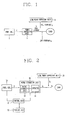
- FIG 1 is a block diagram illustrating a conventional power supply apparatus for a line connection type fuel cell system.
- the conventional power supply apparatus includes a fuel cell 1, a power converting unit 2, and a line power supplying unit 3.
- the fuel cell 1 includes a stack (not shown) comprised of an anode and a cathode for generating electricity by electrochemical reactions of hydrogen and oxygen, and generates a DC voltage from the stack (not shown).
- the power converting unit 2 includes a DC/DC converting unit (not shown) for converting the DC voltage into an AC voltage, boosting or dropping the AC voltage, rectifying the resulting voltage, and outputting a DC voltage.
- the power converting unit 2 also includes an inverter (not shown) for converting the DC voltage from the DC/DC converting unit into an AC voltage.
- the line power supplying unit 3 supplies common power to each house or public facility (load). That is, the fuel cell system and the line power supplying unit 3 are linked to each other, for supplying power to each house or public facility.
- the present invention provides a power supply apparatus and method for a line connection type fuel cell system which can improve operating efficiency and economical efficiency of the fuel cell system, by presetting a normal region which is a stable operating region of a fuel cell, detecting a current operating point of the fuel cell according to an output voltage, an output current and an operating condition of the fuel cell in sale of the fuel cell, and automatically controlling the output current of the fuel cell to be maximized so that the detected operating point can exist in the normal region.
- a power supply apparatus for a line connection type fuel cell system, including: a storing unit for pre-storing a normal region and a warning region according to an operating condition of a fuel cell and a correlation between an output voltage and an output current of the fuel cell; and a control unit for detecting an operating point on the basis of the operating condition of the fuel cell, comparing the detected operating point with the normal region and the warning region, and outputting a control signal for increasing or decreasing the output current of the fuel cell according to the comparison result.
- Another embodiment is directed to a method for a line connection type fuel cell system, including the steps of: detecting an operating point of a fuel cell; comparing the operating point with a normal region and a warning region; and varying an output current of the fuel cell according to the comparison result.
- Embodiments of the present invention relate to a power supply apparatus and method for a line connection type fuel cell system which can improve operating efficiency and economical efficiency of the fuel cell system by automatically controlling an output current of a fuel cell to be maximized.
- the power supply apparatus for the line connection type fuel cell system may include a fuel cell 10, a power converting unit 20, a line power supplying unit 30, a control unit 40 and a storing unit 50.
- the fuel cell 10 includes a stack (not shown) comprised of an anode and a cathode for generating electricity by electrochemical reactions of hydrogen and oxygen, and generates a DC voltage from the stack (not shown).
- the power converting unit 20 converts the DC voltage from the fuel cell 10 into a predetermined level AC voltage and outputs the AC voltage.
- the power converting unit 20 includes a DC/DC converting unit 21 and an inverter 22.
- the DC/DC converting unit 21 converts the DC voltage into an AC voltage, boosts or drops the AC voltage, rectifies the resulting voltage, and outputs a DC voltage.
- the inverter 22 converts the DC voltage from the DC/DC converting unit 21 into an AC voltage according to a control signal, and outputs the AC voltage.
- the DC/DC converting unit 21 varies an output current according to a control signal, such that the fuel cell system illustrated in Figure 2 operates in a normal region.
- the line power supplying unit 30 supplies common power to each house or public facility (load).
- the storing unit 50 presets and pre-stores a normal region which is a stable operating region of the fuel cell 10.
- the storing unit 50 may also pre-store a warning region.
- the warning region may be determined by using load characteristic curves by an operating condition of the fuel cell 10 and a correlation between an output voltage and an output current of the fuel cell 10.
- the normal region and the warning region may be set on the basis of characteristic curves by the operating condition, as determined by the output current and the output voltage of the fuel cell 10 and preset load corresponding curves.
- the control unit 40 detects an operating point of the fuel cell 10, compares the operating point with the normal region and the warning region, and outputs a control signal for increasing or decreasing the output current of the fuel cell 10 according to the comparison result. That is, when the detected operating point exists in the warning region, the control unit 40 may decrease the output current of the fuel cell 10. When the detected operating point exists in the normal region, the control unit 40 may increase the output current of the fuel cell 10. When the detected operating point does not exist in the normal region or the warning region, the control unit 40 stops, i.e., disables, the fuel cell system.
- power generated in the fuel cell system may be sold to a load, such as a power company or a residential or commercial application.
- the generated power can be maximally supplied to the load, for demanding payment from the load.
- the current may be maximized to generate the maximum output.
- Figure 4 illustrates one embodiment of a method of operating a power supply apparatus for the line connection type fuel cell system in accordance with the present invention.
- the storing unit 50 presets and pre-stores the normal region which is a stable operating region of the fuel cell 10 and the warning region on the basis of the characteristic curves by the operating condition of the fuel cell 10 and the correlation between the output voltage and the output current of the fuel cell 10, and the load corresponding curves, as illustrated in Figure 3.
- the operating condition may include an air quantity and a fuel quantity supplied to the fuel cell 10, and an external temperature.
- the DC/DC converting unit 21 converts the DC voltage from the fuel cell 10 into an AC voltage, boosts or drops the AC voltage, rectifies the boosted or dropped AC voltage into a DC voltage, and applies the DC voltage to the inverter 22.
- the inverter 22 converts the DC voltage from the DC/DC converting unit 21 into a predetermined level AC voltage according to the control signal, and outputs the AC voltage.
- the control unit 40 detects the operating condition, the output current and the output voltage of the fuel cell 10 (S1 and S2), and detects the current operating point of the fuel cell 10 by using the detected operating condition, output current and output voltage (S3). The control unit 40 determines whether the detected operating point exists in the normal region (S4).
- the control unit 40 decreases the output current of the fuel cell 10, for example, by decreasing the output current of the inverter (S10).
- the control unit 40 decreases the output current of the fuel cell 10 by controlling conversion (boosting or dropping) of the DC/DC converting unit 21 of the power converting unit 20. That is, the control unit 40 lowers the output voltage of the fuel cell 10 by dropping the DC voltage generated in the fuel cell 10 by the DC/DC converting unit 21.
- the control unit 40 decreases the output current of the fuel cell 10 until the detected operating point exists in the normal region.
- the control unit 40 stops the operation of the fuel cell system (S9).
- the control unit 40 increases the output current of the fuel cell 10, for example, by increasing the output current of the inverter (S6).
- the control unit 40 decreases the output current of the fuel cell 10, for example, by decreasing the output current of the inverter.
- the output current of the fuel cell system can be outputted with the maximum value in the normal region range of the fuel cell system.
- conventional power supply systems may set operating points 1, 2, 3 and 4 as the probable minimum voltage of the fuel cell.
- the fuel cell system is stopped.
- the output current of the fuel cell is reduced so that the fuel cell system can be operated in operating points 5, 6 and 7.
- the power supply apparatus for the line connection type fuel cell system presets the normal region which is a stable operating region of the fuel cell, detects the current operating point of the fuel cell according to the output voltage, the output current and the operating condition of the fuel cell in sale of the fuel cell, and automatically controls the output current of the fuel cell to be maximized so that the detected operating point can exist in the normal region.
- operating efficiency and economical efficiency of the fuel cell system can be improved.
Applications Claiming Priority (1)
| Application Number | Priority Date | Filing Date | Title |
|---|---|---|---|
| KR1020050122719A KR100664090B1 (ko) | 2005-12-13 | 2005-12-13 | 계통 연계형 연료전지 시스템의 전원공급 제어장치 및 방법 |
Publications (1)
| Publication Number | Publication Date |
|---|---|
| EP1798797A1 true EP1798797A1 (de) | 2007-06-20 |
Family
ID=37866748
Family Applications (1)
| Application Number | Title | Priority Date | Filing Date |
|---|---|---|---|
| EP06025730A Withdrawn EP1798797A1 (de) | 2005-12-13 | 2006-12-12 | Vorrichtung für Stromversorgung und Verfahren für netzangeschlossene Brennstoffzellenvorrichtung |
Country Status (4)
| Country | Link |
|---|---|
| US (1) | US7858249B2 (de) |
| EP (1) | EP1798797A1 (de) |
| KR (1) | KR100664090B1 (de) |
| CN (1) | CN1983760A (de) |
Families Citing this family (5)
| Publication number | Priority date | Publication date | Assignee | Title |
|---|---|---|---|---|
| KR20080081523A (ko) * | 2007-03-05 | 2008-09-10 | 삼성전자주식회사 | 고온형 연료 전지 시스템을 이용하는 가전 시스템 및 그과열 스팀 공급 방법 |
| JP4320788B1 (ja) * | 2008-01-28 | 2009-08-26 | 株式会社村田製作所 | Dc−dcコンバータ |
| JP5737521B2 (ja) * | 2012-03-05 | 2015-06-17 | トヨタ自動車株式会社 | 電源システム |
| KR20210039706A (ko) * | 2019-10-02 | 2021-04-12 | 주식회사 엘지화학 | 병렬 연결 셀의 연결 고장 검출 방법 및 시스템 |
| JP7186743B2 (ja) * | 2020-04-17 | 2022-12-09 | 富士電機株式会社 | 電力変換装置 |
Citations (4)
| Publication number | Priority date | Publication date | Assignee | Title |
|---|---|---|---|---|
| GB2054220A (en) * | 1979-07-23 | 1981-02-11 | United Technologies Corp | Controlling power flow between an electrochemical cell and a power grid |
| WO2003010841A2 (en) * | 2001-07-25 | 2003-02-06 | Ballard Power Systems, Inc. | Fuel cell ambient environment monitoring and control apparatus and method |
| US20050136311A1 (en) * | 2000-10-03 | 2005-06-23 | Tetsuya Ueda | Power generation control system, power generation control method, program, and medium |
| US20050184594A1 (en) * | 2004-02-20 | 2005-08-25 | Fredette Steven J. | Electric storage augmentation of fuel cell response to AC system transients |
Family Cites Families (2)
| Publication number | Priority date | Publication date | Assignee | Title |
|---|---|---|---|---|
| JP3767639B2 (ja) | 1996-02-29 | 2006-04-19 | 株式会社エクォス・リサーチ | 燃料電池スタックの運転状態判別方法及び運転制御方法 |
| MXPA02000712A (es) * | 1999-07-27 | 2002-07-22 | Idatech Llc | Controlador de sistema de celda de combustible. |
-
2005
- 2005-12-13 KR KR1020050122719A patent/KR100664090B1/ko active IP Right Grant
-
2006
- 2006-12-11 US US11/609,255 patent/US7858249B2/en not_active Expired - Fee Related
- 2006-12-12 EP EP06025730A patent/EP1798797A1/de not_active Withdrawn
- 2006-12-13 CN CNA2006101669526A patent/CN1983760A/zh active Pending
Patent Citations (4)
| Publication number | Priority date | Publication date | Assignee | Title |
|---|---|---|---|---|
| GB2054220A (en) * | 1979-07-23 | 1981-02-11 | United Technologies Corp | Controlling power flow between an electrochemical cell and a power grid |
| US20050136311A1 (en) * | 2000-10-03 | 2005-06-23 | Tetsuya Ueda | Power generation control system, power generation control method, program, and medium |
| WO2003010841A2 (en) * | 2001-07-25 | 2003-02-06 | Ballard Power Systems, Inc. | Fuel cell ambient environment monitoring and control apparatus and method |
| US20050184594A1 (en) * | 2004-02-20 | 2005-08-25 | Fredette Steven J. | Electric storage augmentation of fuel cell response to AC system transients |
Also Published As
| Publication number | Publication date |
|---|---|
| US20070134529A1 (en) | 2007-06-14 |
| KR100664090B1 (ko) | 2007-01-03 |
| CN1983760A (zh) | 2007-06-20 |
| US7858249B2 (en) | 2010-12-28 |
Similar Documents
| Publication | Publication Date | Title |
|---|---|---|
| US7939213B2 (en) | Fuel cell system and electric vehicle including the fuel cell system | |
| EP1770814A2 (de) | Regelvorrichtung und entsprechendes Steuerverfahren für Brennstoffzellensystem | |
| EP1798798A1 (de) | Vorrichtung für Stromversorgung und Verfahern für netzangeschlossene Brennstoffzellenvorrichtung | |
| EP1796241B1 (de) | Stromsteuerungseinrichtung und Verfahren für Brennstoffzellensystem | |
| US8187761B2 (en) | Power supply apparatus and method for line connection type fuel cell system | |
| KR20200020513A (ko) | 연료전지 차량의 외부 전력 공급시스템 및 공급방법 | |
| US7858249B2 (en) | Power supply apparatus and method for line connection type fuel cell system | |
| US20090102291A1 (en) | Fuel-Cell Based Power Generating System Having Power Conditioning Apparatus | |
| JP4629319B2 (ja) | 電源装置 | |
| US20060228594A1 (en) | Method for shutting down fuel cell and fuel cell system using the same | |
| US20070048570A1 (en) | Fuel cell capable of load-dependent operation | |
| KR20070039359A (ko) | 연료 전지 제어 방법 및 연료 전지 시스템 | |
| JP4055409B2 (ja) | 燃料電池の制御装置 | |
| KR20110122551A (ko) | 연료 전지 시스템 및 그 구동 방법 | |
| US20130337355A1 (en) | Direct oxidation fuel cell system | |
| US20070075587A1 (en) | Power converting apparatus for fuel cell and method thereof | |
| US7700206B2 (en) | Fuel cell system | |
| JP4941167B2 (ja) | 燃料電池の制御装置 | |
| JP4831063B2 (ja) | 燃料電池システム | |
| KR100722107B1 (ko) | 연료전지 전력 출력 방법 | |
| KR20080027702A (ko) | 연료전지 시스템의 직류/직류변환장치 | |
| KR100774464B1 (ko) | 연료 전지를 포함하는 전기 공급시스템의 정전 알림 장치및 그 제어방법 | |
| JP2012038457A (ja) | 燃料電池の発電制御装置、燃料電池発電システム、燃料電池の発電制御方法、およびプログラム |
Legal Events
| Date | Code | Title | Description |
|---|---|---|---|
| PUAI | Public reference made under article 153(3) epc to a published international application that has entered the european phase |
Free format text: ORIGINAL CODE: 0009012 |
|
| AK | Designated contracting states |
Kind code of ref document: A1 Designated state(s): AT BE BG CH CY CZ DE DK EE ES FI FR GB GR HU IE IS IT LI LT LU LV MC NL PL PT RO SE SI SK TR |
|
| AX | Request for extension of the european patent |
Extension state: AL BA HR MK YU |
|
| 17P | Request for examination filed |
Effective date: 20070627 |
|
| 17Q | First examination report despatched |
Effective date: 20070730 |
|
| AKX | Designation fees paid |
Designated state(s): AT CH DE FR GB LI |
|
| STAA | Information on the status of an ep patent application or granted ep patent |
Free format text: STATUS: THE APPLICATION IS DEEMED TO BE WITHDRAWN |
|
| 18D | Application deemed to be withdrawn |
Effective date: 20090205 |